The first few days were occupied with re-wiring the car and installing the motor controller, as most of the plugs and the configuration of the controls had been changed in the new version controller with the MC33033 chip. The first on-car test of the motor with the mechanical torque multiplier on December 6th failed: like the wave power machine there was too much play in the linkage. The problem seemed easily fixed, but then a problem developed with the motor controller and I had to divert attention to fixing it. (cause: loose screws to the heat sink let transistors overheat and one burned out.)
Then life put the work on hold. It got too cold to work or test outside (no heated garage) - even inside I spent much time sitting near the woodstove. I spent time filling out SR & ED tax credit claim papers to get back a portion of the $13,000 I spent or otherwise invested in R & D for 2008 - not exactly a salary, but the only government assistance I am able to access. (My 2007 claim was rejected without CRA telling me. Waiting for news that never came led to months of delay before doing 2008. I'm doing the 2008 claim - I still didn't get it finished and it's now "urgent" - differently.) When the weather warmed up, it started pouring rain.
As I had "uninstalled" the motor controller, I sought out and found a better 150 amps main breaker/power switch that allowed everything to fit properly in the controller/wiring box. (Physically smaller than the $5 surplus house main breaker, and only 10x the price.) In addition, I sourced out the "best" brake rotor disks for making the motors and more ideas for electric heating and window defogging.
Finally back at the car, the torque pulses were still being taken up in slack - the rotor was was theoretically coupled to the wheel, but despite attempts to beef things up, it was vibrating back and forth with the torque pulses without the wheel turning, and I decided the torque rotor would have to be solidly bolted onto the wheel out near its rim.
On considering this arrangement, I saw that it could actually make for valuable configuration improvements. Once the revisions had been made, testing revealed that the play had simply been converted to vibration, making the motor jump around. I thought the fit was better than that! Where to go from here? Well, invention is discovery!
Then it was Christmas.
It occurred to me that our Prime Minister is the only Canadian who can decide to create, eliminate or restructure a government department. On January first, my birthday and "the start of a new decade in the progressive evolution of human affairs", I wrote him a letter with the idea for a government Department of Progress overseen by a government minister, with my previous letter to the Finance Minister and additional supporting material enclosed.
On the 10th I watched "Fuel" at the Imax, a film focusing mainly on using biodiesel (AKA cooking or vegetable oil): burning clean, renewable oil from plants in place of dirty oil from fossil fuel. And it seems there's a way to make it with fast-growing algae "farmed" in tanks in desert areas, a system worked out in the 1970's under president Carter's National Energy Policy. Rudolf Diesel in fact invented his engine to run on vegetable oil, as an alternative to gasoline engines.
At least one of the film's sponsors makes bio-diesel near Duncan, and drove to the film using it. There are at least two filling stations, in and near Duncan. More info?: www.CowichanEnergyAlternatives.org or www.DrBjornsAuto.com (does biodiesel "conversions").
With no evident recognition in the film of the role of the petroleum industry in methodically killing non-petroleum transport, I was struck by the mention of what sounded like a typical petroleum propaganda blitz, this one against bio-diesel, fed to the media as "news" and nicely calculated as usual to undermine public support for the alternative by blowing its negative points way out of proportion and not mentioning the benefits. (eg, saying food crops are diverted to fuel production while people starve in the third world - whether there's any connection or not - and not mentioning the algae farms that could prevent such diversion.) In keeping with the technique, this should be followed by clandestine attempts to sabotage or buy out and shut down any major sources of bio-diesel fuel. As part of the sabotage, I recently heard elsewhere that the automakers are now deliberately making modified fuel injectors that won't work with plain bio-diesel fuel. (Stay tuned for the next stage: "news" about unhealthy additives and processing needed to make bio-diesel work, without of course any mention that this is because of the injectors.)
Instead, the film speaks of "personal responsibility" for the world getting off petroleum. Again we see the need for a government Department of Progress to guard the public interest, here to help get the algae farms up and running or otherwise ensure a good supply is available at the pumps, and to ensure that a whole technology isn't supressed by vested interests.
Even with good plug-in hybrids, biodiesel could perhaps be a great fuel for longer distance driving, and for aircraft.
Just before the end of the month, I saw an oil company TV ad about growing algae to make biodiesel oil. I doubt if they're serious about actually doing it. I'd guess they're very scared of electric and plug-in hybrid cars. They seem currently to be doing their best to divert the public's attention from them, eg, with massive general TV ad campaigns for gasoline cars, and bringing in biodiesel at this point seems like a good tactic to cloud the whole issue. And at the "worst", if biodiesel "happens" they want to be in control of it.
Although this car ad blitz is coming from many "competing" car companies, "big oil" doubtless controls the lot of them. There seems to be a complex web of auto company share ownerships, and control is likely by proxies that probably can't be directly traced to the oil companies themselves. This was brought home in the documentary "Who Killed the Electric Car?", when car companies were forced by California to produce a certain percentage of non-polluting cars. 1. Every car company would only lease electric cars and not sell them. 2. As soon as California law allowed, every car company had every electric car taken back and crushed, over howls of protest. The central control is evident. Who in their right mind would believe these happened to be multiple identical, simultaneous decisions, all taken independently by each and every car maker?
(Scared of electric cars? I'll repeat myself: Chevron, via "Cobasys", has car size Ni-MH batteries locked in a box for decades to come by buying up 125 related patents, and they'll probably acquire every new one that comes out. They probably dictate the price of the smaller ones, too, as they never seem to drop much below 1000 $/KWH regardless of battery size or manufacturer.)
Look for all the promising plug-in hybrid developments like the Chevy Volt and the Mitsubishi electric car to quietly peter out and amount to nothing, or to be unaffordable, owing to their manipulations. (May I please be proven wrong!) Mitsubishi probably took the oil companies by surprise since they've never made cars before, but one can guess that oil company proxies are now out there quietly buying up Mitsubishi shares and working to divert the project.
At the top of this vast network of power and control are probably a very few gangsters. I saw part of the film "Nixon" on TV recently and found it illuminating. It was implied that mafia bosses with oil interests had John and then Bobby Kennedy done in to pave the way for getting their favourite, Nixon, into the white house. Current public institutions and laws are evidently inadequate to prevent the private accumulation of the sort of power and wealth that can have such things - all of the things above - done, seemingly with impunity.
I keep thinking of NRC and their insistence that any recipient of their funding is required to patent their created technology. First, to me it seems to defy logic that public money should be rigidly required as a matter of fixed policy to create proprietary technology unavailable to the public.
Second, since patents for non-petroleum transportation technology all seem to end up under the control of an oil company, priceless new technologies are suppressed until those involved are gone and everyone has forgotten they exist - they are killed dead. And other manipulations are also used to the same end, usually with a car company or other proxy taking the blame so the oil companies maintain a "clean" image. (Eg, GM and Constantinesco's mechanical torque converter in 1923.) If the electric light bulb were invented today, they'd buy up the fledgling light bulb maker and close it down before many or any were sold, to keep us using kerosene in lanterns.
Hence, my quest for an add-on system that's easy to make anywhere, without specialized equipment, and also my freely publishing my work rather than patenting it, even though this (not to mention the terms for accessing government R & D money that effectively make it completely inaccessible regardless, even to Canada's top inventors) disqualifies me from making any sort of a living for developing some things Canada and the world very much want and need, and which few people would be able to create.
December In Detail
I spent the first few days of December rewiring things in the car.
First, the gas pedal rheostat now needed all three wires connected instead of just two, so I pulled it out and re-did it. Before I took it off, I tested it with a meter, pressing the gas pedal, and found that it was still working properly after about a year.
Then the motor controller has a "motor disable not" pin with a pull-up resistor instead of what seems more logical, a "motor enable not" pin. This inverse sense has repercussions: First, if the controls aren't connected, the motor defaults to "run" instead of "idle". Second, a switch has to be turned "ON" instead of "OFF" to put the motor into "neutral". My preference of a "Forward-Off-Reverse" switch had to be replaced by "Off-Reverse-Forward" to work with any ordinary sort of on-off-on switch. (I suppose I could have used two switches, but then I'd have to find room for and install the second one. So I rewired the switch.)
With both controls rewired, the connector on other end of the operator controls cable also had to be rewired, for the new socket type on the new (relatively speaking) motor controller.
Finally, the motor itself now had the 75 amp rated APP connector while the car still had the homemade socket from before I found the APP system, so the car's motor connector had to be replaced.
After that, the system was to be fitted on the wheel "sprung" instead of bolted to the axle, and a "thrust plate" and some changes to the mounting brackets had to be made.
It's December, so the days are cold and daylight short. Only an item or two could be managed in a day. By the 6th everything was ready for testing. The motor ran fine, and the torque converter had a first test, which is described in that section.
In a second test on the 8th, the motor didn't run right. Then it got really cold, putting a stop to the work. (oh, for a heated garage!)
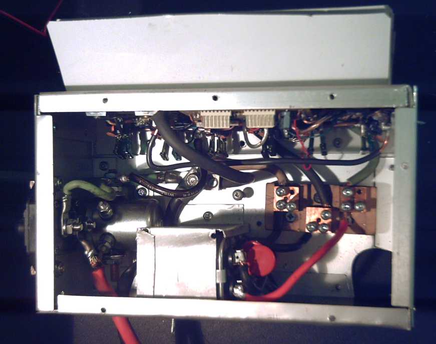
By the 15th it was getting warmer and I had the motor controller dismounted and inside. I found a single blown mosfet. When I went to replace it, I found out why: the screws holding the mosfets onto the heatsink were all loose. I had removed them last time I redesigned the controller and (evidently) not retightened them. It worked fine until the motor had a load, then they started overheating. Doubtless it was the MC33033's dynamic current limiting system that prevented the shorted transistor from "taking out" some or all of the others.
Also of interest, most of the skinny leads of the DC supply filter capacitors next to the transistors were blown, even though the capacitors themselves seemed okay. This probably happens when the motor direction switch is reversed with the motor spinning, which turns on the high side mosfets of all three phases, shorting the motor coils regardless of the PWM setting, to bring it to an "instant" stop. That would make for some pretty nasty spikes! 100uF/200V capacitors have fatter leads than the installed 100uF/100V ones, so they may prove necessary even at just 36 volts. (Last year, some 50V or 64V cap.s actually blew up! In addition to the increased voltage rating, I doubled the number from 3 to 6, one for each pair of mosfets.)
When I went to pull the motor controller from the car for repair I ran again into the curse of the motor coil filter capacitors being mounted covering the wiring connections. This was caused by the bulky "house main" circuit breaker taking up too much room in the cabinet, forcing me to move other components around to fit everything in. This was my main remaining beef with the motor controller chassis layout, and I had planned "some time" to locate a smaller breaker for the finished design.
I decided this was the time! I looked for one rated for DC volts as well as AC. From what I saw, most breakers showing both AC and DC ratings, if rated for 240 VAC, were also rated for at least 40 volts DC, although a few were just "32 VDC". But all the "regular" breakers over about 60 amps are double - similar to the one I wanted to remove.
I searched hell and high water for a small single 150 amp breaker, and of the few choices available, it seemed to boil down to two panel mount breakers from Blue Sea Systems (from the "high water"): Their BSS7004 and BSS7048 models looked the most suitable. The 7004 has a push-button "off" and a lever to turn it on again. It was around $45. The 7048 has a swinging arm for on and off. It was around $65.
I am slightly concerned that the pushbutton "off" would be easy to trip while driving if hit by luggage or by someone's elbow. The lever arm wouldn't be entirely safe either. A guard around the breaker might be in order in many installations.
A 135 amp breaker should be plenty big enough and better protection (BSS7015 & BSS7047). 120 amps would probably work fine too (BSS7013 & BSS7046.) I just wanted to have plenty of "headroom" to make sure it would never, ever trip when I "floored" the motor on the street, without taking the trouble (and expense) to try out different size breakers. (So far a 100 amp breaker has never tripped.)
150 amps is the largest size of these types. If it proves too small for a 24 volt Electric Hubcap system, one might have to start the search over again, or accept a double breaker. If a physically large breaker is required, I think I'd expand the cabinet to accommodate it, eg, make it 13" tall instead of 10". (That wouldn't have fit in my chosen space in the car, but every installation will be different.)
It seemed worth while. The BSS7004 breaker hardly takes up any room inside. I put all the components back where they were originally mounted and wow!, now the box has adequate room for everything!
Sigh, I guess this means updating the motor controller making manual!
Additionally, sometimes it seemed the motor didn't want to start spinning, though it had lots of power once going. I thought this might be because of the low PWM frequency I chose, so I changed capacitor C7 from 0.1uF to 0.022uF to increase it from a medium tone to a high pitched squeal. It was worse! I had to start it spinning by hand. So I increased it instead, to 0.2uF. Then the motor had plenty of starting thrust. This seems completely counter-intuitive, but low PWM frequency has less switching losses and thus less heat in the controller, so it seems to me preferable. It's headed down towards the frequencies I was using when I didn't know about the ready-made motor controller chips. An audible frequency also avoids the system being an unrecognized ultrasonic irritant.
I measured no load current in one phase wire with a 36 volt supply. They seemed similar to those in the tests a few months ago. Differences to the equipment are first the hall effect magnet position sensors in place of the optical system, second that the heavy torque converter was mounted, although spinning freely, and third the change to a lower PWM frequency. Before the PWM change, currents measured about 20-30% higher than shown below. The reason isn't clear. It's possible the ampmeter doesn't respond very well to higher frequencies (the PWM) and that none of the readings are very accurate.
| RPM |
CCW - Amps |
CW - Amps |
| 500 |
5.8 |
5.9 |
| 600 |
6.2 |
6.3 |
| 800 |
6.9 |
7.1 |
| 1000 |
7.3 |
7.6 |
But at the end of the month I seem to have discovered a catch: at the new lower frequency, the motor will only get up to about 1100 RPM (no load), whereas before I'm sure it went beyond 1500 at less than full "throttle" and I didn't try to find the max (with the open motor spinning on the bench right in front of me). It seems further adjustments will be necessary.
Last month I wrote of someone's idea to use 12 volts heaters in series, eg, three heaters for the 36 volt system. There are some weaknesses to this plan. First, I started worrying about the safety of the type I'd purchased. (though, I found a better looking type later for the same price at a marine store.) Second, the amount of heat is fixed. Three 150 watt heaters is 450 watts, period. That's not much for melting ice off the windshield on a cold morning, but it's too much for a longer drive on a merely cool day.
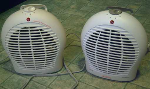
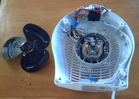
Then in a store I saw a 750/1500 watt household heater for just $20. I looked and saw it had two wound coils each forming a circle around the periphery of the fan blades. I bought one and found that the coils don't even glow red hot. (at least not if the fan is working.) Later I bought another one at another store for just $8! (A 1500 watt heater can use $8 of electricity in just 3 days!) One is "HomeMax", the other is "Sunbeam". (Obviously unrelated manufacturers - the colours are different!)
The plan that occurred to me was to split both coils into three equal sections. Since each coil is 750 watts at 120 volts, each section would be 250 watts at 40 volts, or 200 watts at 36 volts. (well... 202.5 watts)
Then I worked out a circuit to switch them. The existing switch has "off", "fan", "low" and "high", 4 positions. The current of each heater segment is slightly less than the original current of each element, so the "low" and "high" positions could each turn on one segment, 200 or 400 watts.
A new double pole toggle switch, on-off-on, rated 25 amps (each pole) will be added. In the middle, the heater is off. Up, the switch turns on the fan and one 200 watt heater element: "Low". Then the original switch can add one or two more: 200 - 400 - 600 watts. Down, the switch does the same as "up", but also turns on all three segments of the other element, adding 600 watts: "High", 800 - 1000 - 1200 watts. Thus this one added switch plus the existing one provides great incremental control over the amount of heat to defog the windshield and warm the car quickly and then provide just enough to keep it comfortable.
Of course, heating the car off the batteries will reduce the vehicle range. At 200 watts, the heater will draw about 6 amps, and at 1200, 34 amps. (I should also install thermal cutout switches in all three segment areas, or at least get one rated for 34 amps.)
To get lesser heats or finer gradations, one could use one of the coils in halves instead of thirds (makes two 135 watt elements), use 2/3 and 1/3 (100 and 200 watts), or simply put 36 volts across a whole coil (68 watts). However, such arrangements would reduce the maximum heat or considerably complicate the switching. The 200 watt increments with two switches seems more practical, allows maximum heat, and not least isn't too confusing to operate.
A good operating plan to reduce the amount of battery drain from the heater, is to preheat the car before starting out, with a heater running on house power. (But be sure it's safely set up!) This would take additional setup and planning, and you either need to know when you're soon to leave or else leave it on all the time in cold weather. But presumably the car is plugged in anyway to recharge the batteries. I tried this once with a 400 watt heater - it was great to come out to a warm car with the frost melted off the windshield!
The other part of the plan is a little more difficult. The 120 VAC fan, made to fit the heater, won't run on DC, nor on 36 volts. A common computer type fan won't fit properly.
It seemed to me a DC to AC inverter should run the fan motor okay since it was quite low power. All the common ones convert 12 VDC to 120 VAC, but we have 36 VDC going into the heater.
One option is to buy a 12 VDC to 120 VAC inverter and either feed in separate 12V power for the fan or put in a voltage regulator to drop the 36 volts to 12 volts. Feeding separate power would really complicate the switching, and a situation where the heater was on but the fan wasn't running would be dangerous. Using a regulator and inverter means paying several tens of dollars for the inverter and yet still having to build an electronic circuit.
So why not make a 36 VDC to 120 VAC inverter instead? I found a promising circuit diagram on the web, but unfortunately, Hammond doesn't seem to make an appropriate (small 72 volt center tapped to 120 volt) transformer, and there's really nowhere else to buy transformers.
I wondered if a transformer made just by winding coils around a core similar to my motor coil cores would work. Most transformers have the iron laminates wrapping around, an "EI" shape with the coils wound on the middle bar of the "E", to complete the magnetic circuit. (or a toroid.) I decided to simply make one and see what happened. I used 180 turns of #22 wire for the 120 volt side and 108 turns of #19 for the 72 volt side.
Unfortunately, when I plugged it in it buzzed loudly, the meter read 11 amps and the overhead light on the same circuit dimmed perceptibly. Nope! It needs that magnetic circuit completed. (It was probably also not enough turns of wire, notwithstanding the large core size.) I guess all I made was an electromagnet.
There was however a second experiment within this experiment. The wires have to be immobilized, and common practice is to dip the transformer (or motor, electromagnet...) in motor varnish and bake it in an oven at about 450 f to harden it. This makes noxious fumes so you can't do it indoors. (I used a toaster oven out on the patio for the motor coils.)
In this construction I put it in a tin and filled it with sodium silicate solution - "water glass" from the pottery supply store. I then put it in the kitchen oven at 250 f. It didn't work quite like mixing it with clays. It seemed the water had to escape, boil off, for the sodium silicate to harden. It bubbled up and overflowed, and a hard crust formed on top. I ended up pushing it all back down with a spoon several times, and it took a couple of hours, where the motor varnish is under an hour and no need to inspect it in the oven.
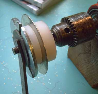
Coil Winder Bobbin for 1/2" thick coils
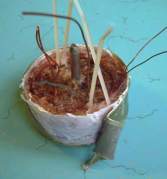
Peeling off the small salmon tin that the coil was "cooked" in. I snipped the top edge and wound off the tin with pliers. The pin in the center makes a mounting bolt hole.
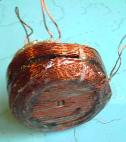
The "finished product", two coils with tarpaper between, my usual nail gun finishing nail strip "laminates", all cast in hardened "water glass".
The end result was a coil in sodium silicate "glass" instead of motor varnish or cast epoxy. It seemed great! But normally with water glass one fires the ceramic and vitrifies everything. Here, the unfired water glass will reabsorb water and dissolve. It could work well in a warm, dry location... but not on a motor mounted on a car wheel!
It can also work for experiments such as this one. I put the coil in a container of water, and in an hour this solid object was all separated back into its individual elements - coiled wires, nail strips and a piece of tarpaper.
My biochemist brother has suggested that if I added calcium it would become insoluble and the setting would be permanent. (How about calcium carbonate or barium carbonate?) Oh well, some other time!
-----
So I considered what other options there were for driving the fan. I looked at the motor itself. It appeared that the laminates could be tapped apart to expose the coils, which could then be rewound with 36/120ths of the length of wire, of 3.33 times the cross section area to make the motor 36 volts instead of 120. Or, the same wire could be cut into three equal lengths and wound in parallel. That way, no transformer would be needed.
The theory was good. The motor core tapped apart with a hammer and screwdriver and the plastic coil formers pulled off easily. The fine wires weren't varnished (!), so they could easily be unwound. I started unwinding and counting turns. I was expecting 200-300 turns on this very small spool, but as I unwound my estimates keep going up. In the end, I counted 1340 turns and the fine wire caught in every little thing and became a tangled mess. The diameter of the wire measured 0.006". Subtracting 0.002 for the insulation that made it... way finer than my wire gauge tables went! Maybe #36?
That meant that I'd have to rewind each of the two coils of the motor with 402 turns of about #32(?) wire by hand. Even if a local motor shop has such fine wire, I could just see more tangled wire, losing count and frustration, and decided that it wasn't really doable.
Then it occurred to me that the two coils of the motor were in series. If I simply cut the wire between them and put them in parallel, it would become a 60 volt motor instead of 120 volts. That's closer to 36 volts. Could it be close enough? Motors are fairly flexible.
I tried running the fan on 64 volts from a transformer, equivalent to 32 if the coils were in parallel. The motor barely started (one time I had to shake the heater) and it didn't blow much air. I tried again with 78 volts (39 volts), and here the fan started slowly but surely and blew a perceptible amount of air. Those were the closest available voltages. All in all, pretty marginal performance, especially if the batteries were a bit low.
Hammond has a selection of 36 volt center tapped transformers that could be used to step up to 60 volts. So, providing I could cut the wire between the two coils into two and successfully solder leads to them, and providing the inverter circuit worked (it most likely will), it becomes doable. But not simple!
-----
But finally I began to think that the better solution is to simply take the heating element assembly, a computer fan, and create a new housing to fit them. The 36 volts can easily be dropped down to 24 for a 24 volt fan, with a simple 5 watt resistor. It's the only solution that doesn't seem to require designing and building a solid state electronic circuit. Instead, it's simple plastic (and aluminum?) work - cutting, bending, gluing and screwing.
Furthermore, the original housing is rather bulky. It has "waste" space all around, and it will be easy to reduce it to much better dimensions for car use, and put it on a swivel mounting at the dash.
Yes, I'm warming to this idea!
Mechanical or Magnetic Torque
Multiplier Project:
Torque Leverage Without Gears
September Details
Torque Leverage Without Gears
September Details
In December, the unit was ready to test on a car, but I first had to change some wiring and plugs on the car, so it wasn't until the 6th I ran any tests.
These failed: like the wave power machine there was too much play in the linkage. The mounting layout layout is in accordance with the "sprung motor" suspension design of last month, which looked really easy to implement when I considered actually doing it.
I thought I'd have to make a new plate to fit between the nuts on the wheel. But then I realized the nuts were a little smaller than the regular ones on the outside (need a smaller wrench) - leftover from the previous mounting scheme. I replaced these with the regular nuts and the change was just about right to eliminate the play.
On the 8th I tried again, but this time the motor, which had had no previous problems, didn't run right, so no tests were possible. Then the weather got really cold for some days (eg, -5c) and I had to quit working on it.
By the 16th I'd brought everything into the house, repaired the motor controller (December Trials, above) and tested motor operation. By that day also it was much warmer (+7c) -- but pouring rain.
December 21st: A couple more trials convinced me that the torque rotor driving via a plate between the lug nuts isn't going to work. Even when it seems tight, the torque rotor vibrates back and forth without the car wheel following. It seems the rotor will have to be bolted solidly to the car wheel, and that the bolts should be nearer the rotor's rim than its center.
However, there seemed to be some good news in this. Since the inertia rotor, spinning inside the output rotor, is driven by pins from the motor magnet rotor, and since it slides up and down on those pins, a natural point to pivot the motor from to effect sprung suspension is created, using tapered pins.
Also, the magnet rotor can be affixed to the base end of the motor axle with the drive pins/bolts sticking out. Then the stator is attached to the axle hub. With only one hub and one pair of bearings, no machine lathe is required to cut down hubs so that two will fit on one axle, simplifying manufacture.
And, perhaps a small point, the motor and torque converter become separate, and can be carried separately, keeping the loads lighter for those of us with weak backs. But the motor will stay in one piece; it doesn't have to be disassembled to mount and dismount it - there's no danger from exposed supermagnets.
However, when this arrangement was tested, it appeared that with no actual connecting shaft, the play had simply been converted to having the motor bounce around. Furthermore, to be able to do up the lug nuts on the wheel, I had had to cut the center out of the rotor, so it can no longer be attached the way it was previously.
Next I'll simply get everything to fit as perfectly as possible and try it again. After that... the design basically seems good, but some improved components and fittings will be in order. A heavier inertia mass plate might help considerably to strengthen the pulses of force.
http://www.turquoiseenergy.com
Victoria BC