As in the later half of December and in January, there were a lot of things requiring my attention in February and diverting it from the torque converter project, so I didn't get very far. That's not to say nowhere, but it was frustrating that mainly this one vital laggard item seemed to be preventing driving the car down the street electrically.
One thing diverting my attention required some weekend trips to Comox, and I stopped in on my way up one day at Canadian Electric Vehicles in Errington. I got a great tour of their shops and drove a fabulous car converted to electricity. Quiet. Simple: Fwd-N-Rev. The gas pedal started the car braking somewhat when you let it up, just the way I'd envisioned as ideal (regenerative braking).
I noticed on the little analog(!) meter that 300 amps would be used while accelerating, while only 50 or even 20 or 10 amps would be returned when braking. To a considerable extent, this disparity would be due to losses in the transmission (the car was permanently set in second gear), which is of course a major reason the Electric Hubcap drive system deals with the car wheel(s) directly. A direct drive system should reduce that 300 amps to 200, with all the savings in motor size and battery requirements that that would imply.
Not only did this side trip give me some small but real experience with the way electrifying cars is done now instead of just theoretical knowledge, I also found they had some 36 volt electric heater cores that looked just about ideal for my pivoting dashboard heater plan. Perhaps just as well I hadn't got around to doing up that car heater yet - this looked pretty simple to put together, with the same fan and switches. And in fact I did get it assembled (plans are below), using my next big score: a sheet metal break for $39.99.
On the next Comox weekend, on the 28th I stopped on my way back at Transfer Beach Park in Ladysmith, a lovely civic park on the ocean. After walking a beach trail, I stopped on my way out to examine a huge old "museum" steam engine to see if anything on it might give me any ideas for the torque converter. It did! I now have a design with two main components that looks so promising I hope to make and try part of it in March, including actually driving the car down the street. This design is so simple, so obviously efficient... and it would seem to be essentially the same as part of Constantinesco's successful design, the recreation of a piece in the photo I hadn't realized the workings of. My design could be closer to Constantinesco's than I expected.
Adopting it would mean radically changing the entire layout philosphy of the drive system. The Electric Hubcap motor probably wouldn't even be mounted on the wheel - a change with serious consequences to its very name. But if one wants to invent "world's best" successfully, one must be willing to step back, recognize a superior idea as better and valuable even though it conflicts with cherished designs which have been established with much effort and which have become part of the basic "assumptions" of what the project is all about, scrap the work and redo it the better way.
Also near the end of the month, I finally decided that if I wasn't having much luck with my perchlorate battery chemistry, I should at least now have sufficient processes and techniques worked out to make very good alkaline batteries, and a nickel-manganese one should at least hold about 65-75% more energy than Ni-MH, a good step up. Other than the nickel, it should be cheap.
Only nickel metal (or 100% nickel plated metal) works in the positive electrode - every other metal soon corrodes away in the alkaline 'positrode' when charging the battery. But on trying to source even a few bits of pure nickel (nickels are not pure nickel), it appears I may pay more per kilogram for nickel than I did for lanthanum a couple of years ago, and that I may well have to buy "production" quantities to get any at all. It seems making one alkaline battery is likely to become a costly endeavor.
February Details
I found a small (~5 x 5 x 1 inches), rectangular, 36-72V electric heater core consisting of four finned resistors, at Canadian Electric Vehicles in area 51 (take exit 51 near Parksville). They're also available for higher voltages. Prices (IIRC) were from 80 to 125 $. I think this one, the lowest voltage unit, was really made for 1500 watts at 48 volts. At 36 volts it's 800 watts - four 200 watt elements. They're wired in series but with access to the midpoints, hence five connection terminals (seen on left side in picture). They're made by DBK and bear the numbers DBK HRKK01-16/14 36-72V L49V. I think they're 'special order' as the voltages on the DBK web site are all 110/240. It seemed pretty much ideal for the car heater I wanted to make, so, having not yet made the heater, I bought it. It was much pricier than the $7.99 'off the shelf' heater from XS Cargo and less than its 1200 watts, but still half the cost of the finished 430 watt golf cart heaters and with substantially more heating power. I suspect if one ordered a bunch, they'd make them however one desired, eg, 1500W at 36 volts.
The components for the heater, with the old 120 volt coils at the front.
All I'll take from that now is the heat safety switch and the rotary switch (left) for Off-Low-Med-Hi: 0 200, 400, 800 watts. 100 and 600 watts would be possible but would need complex switching.
Having all the parts, it needed a chassis. Aluminum chassies may seem a little passé these days, but they won't catch fire if there's a problem with the heater. And - not a trivial detail for one-offs - you don't need an injection mold. I now knew just what I wanted to make, and I had the aluminum.
I had been casting about for an economical sheet metal "break" (bender/folder) for years but had seen nothing under $200, and nothing recently under about $250. Those were just 12" wide units, but I figured that was wide enough for small chassies. Until now, the chief intent was for making motor controller chassies. I managed to put together the last one without one, but it would certainly have simplified things. Now this second and immediate usage spurred my thoughts about them again.
I kept thinking it should be possible to make a cheap break simply by welding some end plates onto lengths of angle iron and putting pins in for a hinge. Then you could just clamp a loose flat piece of metal on top to hold the piece being bent.
But starting yet another project wasn't exactly an appealing idea! I thought I'd give buying one one more try. Was there anywhere else but KMS Tools? Midland Tools in Nanaimo was in the Victoria phone book, so I called. Wow!, they said they had 30 inch breaks, for $90. "Very basic. Not a chassis or box bender." Okay, I'd check them out on Friday. In the meantime, let's look one more time at KMS and see if there's anything new. I drove out there and quickly spotted an "18 inch benchtop sheet metal break"... for $39.99! Wow! I bought it of course.
On closer examination, this break was made by welding some end plates onto lengths of angle iron and putting pins in for a hinge. There was a loose flat piece - you just clamp it on top to hold the piece being bent, with C-clamps. In short, it was exactly what I'd thought of myself!, with a better mounting and very nicely made. I suspect the 30", $90 one at Midland Tools is probably a bigger version of the same thing.
I measured all the parts and put the chassis dimensions on paper. I cut the aluminum sheets with a crosscut blade on the radial arm saw (safety goggles, earmuffs), and trimmed the bits with tinsnips. (Then I marked the dimensions on the actual pieces and foto'ed them - too simple!) I decided to make the top and two sides from one piece, and the the length turned out to be 17-1/2". How thoughtful of KMS to bring in exactly the right size break!
Heater chassis top (and sides) piece, #18 gauge aluminum, showing dimensions and cutouts.
Heater chassis bottom piece, #12 gauge, showing dimensions and cut-outs. I should have made it about 3/16" narrower so it would fit inside the top piece, so change the main face from 2.75" wide to about 2.5625" (2-9/16") and the cut width from 5.25" to 5.0625" (5-1/16").
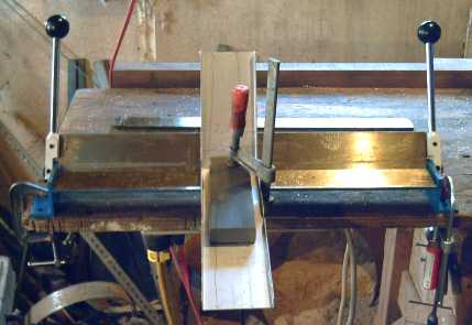
So! The $250 12 inch break wouldn't have been able to do it. (This one was just strong enough - pulling both handles, it was flexing a bit in the middle on the 17" bends, but it did the job. Well, it did say in the instructions something like "Hey, this is a cheap little break made from angle iron, please don't come crying to us when you wreck it on some heavy slab of steel it's way too light for." I'm not sure those were the exact words...)
I sanded the cut edges on the stationary belt sander (otherwise use a file), straightened them up a bit with pliers, and in a fit of decorativeness, polished the top on the polishing wheel. (But I suppose I should paint it all black now so it doesn't make glare at the dashboard reflecting sunlight - and all those awful glaring headlights that seem to have unfortunately become ubiquitous.)
Bending the bottom.
The top piece of metal C-clamped down tended to slide out with the pressure. The answer: more C-clamps, tighter!
I also used my space saving technique of C-clamping the entire tool to the workbench when I need it rather than bolting it down.
The bender proved much more flexible for doing boxes than expected. Where 'regular' benders have movable teeth that are a pain to set up to allow compound folds, with this one you can just use any old short top clamp piece instead of the full length one. Cool!
Do the long folds first, and the short ones after, as per these pictures.
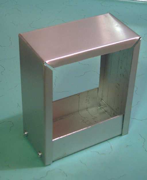
The chassis. The bottom could be made a little narrower so it would fit inside the top piece edges on both sides. might look better. As it was, I had to do a small bit of hacking and have one side inside and one outside.
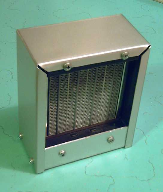
The heater from the heater element side.
The mounting lips had slots for bolts, but that would have meant trying to do them up from the inside.
I drilled smaller holes in the lips to thread sheet metal screws into.
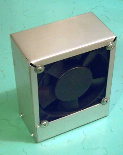
The heater from the fan side. Now it just needs grills.
Oh yes... and wiring, switches and safetys, resistors and zenor diode for the 12 volt fan, and the pivoting mounting. The 'extra' space below the fan and heater element provides room for these items.
I threaded sheet metal screws into the holes in the corners, but they proved to be inside the edge folds of the chassis. Washers made the connection. When the grill is on, it'll be fine.
I spent the whole of the 22nd on this while putting off many things that needed (and need) doing, from getting the break in the morning to finally attaching the fan and heater in the evening. Then of course considerably more time on the 23rd writing this up. Then on March 1st I found some nice grill for it. So here it is, finished -- except for wiring it so it actually works, the telescoping conduit pivoting mounting to aim it any direction, and painting the beautiful polished aluminum some dreary dark color so it won't glint sunlight in my eyes or reflect in the windshield at night.
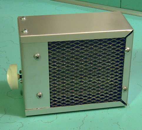
The assembled heater. The switch side (left) is the bottom.
A Broadening Marketplace
A new web search reveals several more 36 volt heater choices on the web than last year when I only found one, and the prices have come down somewhat. In essence, they seem much like this one. Well, I've bought the parts and I'm 2/3 done! Perhaps it will prove to have some advantages. (If I'd used the circular heat element from the $7.99 heater instead of splurging on the nice rectangular one, I could at least say it was cheap!)
The only thing I can say is it'll have 'low-med-high' (200-400-800 watts) with that four position rotary switch, where the commercial models I saw all just have 'low-high'. So nyah, nyah, nyah!
But looking in the parts box, I seem to have practically enough left over to make another complete heater for no additional money! Maybe if 800 watts doesn't seem like enough I'll do the 1200.
I'm not going to try doing a car electric air conditioner. If I was in Texas I might, but in Victoria there's just a few days a year it might be 'kind of nice' instead of just 'in the way'.
Mechanical Torque
Converter Project:
Torque Leverage Without Gears
February Details
Torque Leverage Without Gears
February Details
Regrettably (or perhaps not), I didn't find a lot of time to work on this in February. That's not to say none at all...

I thought, gee, if I just tie the rotor to the hub strategically with some bolts, I could use the original drum despite the center and mounting holes being cut out.
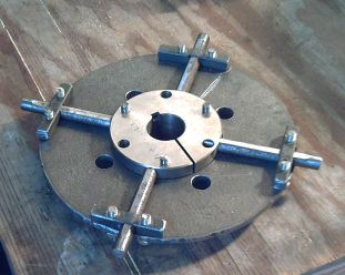
The "SDS" compression fitting I ordered in January arrived and (uncompressed) it's a great fit - slides freely on the axle but has very little play. I drilled holes and put the inner ends of the pins right into it.
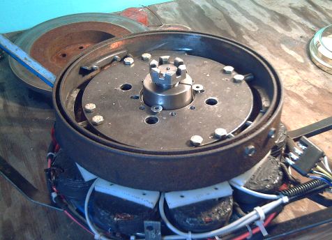
Assembled. The bottom of the rotor needs magnets glued on, but I can't seem to get to that little job (and won't in the next few days, either). The nut is about where it has to sit. I'll have to put it on upside down to get the cotter pin through. (I suppose I could grind the top of the SDS fitting down - ugh.)
Did I have it *almost* right on the very first try last spring?
A new idea has come to me for making a magnetic torque converter. The very first attempt I made was something like an axial flux induction motor, except that the rotating magnetic field was generated by actual rotating supermagnets instead of by electricity with electromagnets. The rotor being turned was a flat aluminum plate with slots.
This arrangement had the advantage that the magnets were going by aluminum rather than steel or other magnets. Since aluminum isn't attracted to magnets, the output rotor wouldn't "cog" magnetically and hinder the motor from starting to turn, but owing to the induced field, it does try to follow along with the magnets.
I thought that in that system was a rotor with enough field strength to turn the car wheel. But I didn't realize that the output torque is never greater than the input torque, and that the slip is only loss and heat rather than a torque increase varying with the difference in speeds.
That meant that the better the coupling was, the more the wheel would slow the motor down, but the car wouldn't move any better than by directly connecting the motor to the wheel. It was a "torque resistor" rather than a "torque transformer".
But, if there were, eg, four turning magnets, and the aluminum was only present at four spots on the output rotor, all the torque would be generated in four pulses per rotation as the magnets lined up with the aluminum. The rest of the time, the motor would be free spinning.
The motor would recover its speed between pulses, and the higher speed would create more torque at the pulse points than a continual drag on the motor, which would keep it from going very fast.
A major consideration for this design is whether it's practical to get enough coupling from such an arrangement without covering too much of the circumference with too many pulse points. You could put in interleaved layers of magnets and aluminum. With enough of them it would be bound to work... but how many would it take? One would be nice... six probably makes it "not a home project".
But, as long as the wheel is turning much slower than the motor, this design would doubtless have some losses. I'm still sure there must be some great way to do a magnetic torque converter with virtually 100% efficiency, no friction and no heat, but this wouldn't really be it. Enter the next idea...
On the last day of the month, looking at an old steam engine, the pin driven by the steam piston made me think of having such an off-center pin on the motor. That could make an arm go back and forth, and some sort of ratchet mechanism on the car wheel could make that back into rotary motion at a different speed than the motor speed. With this conception, I understood a strange looking piece of Constantinesco's converter, which design I confess I hadn't paid much attention to (arrogantly thinking mine must be better).
Why, when one is starting with rotary motion, would one want to convert that to linear back and forth "piston" motion and then back to rotary motion with ratchets? Why not use a pair of gears? It seems totally unintuitive. Answer: the linear motion derived from a given RPM can be converted to a lower RPM output - a wide and potentially variable range of "gear" ratios can be derived, without gears and very efficiently.
With no facility to make more complex special machine parts, there was one potentially big hitch -- what sort of a ratchet mechanism could I use? Surely a bicycle rear wheel piece was too light for a car. In Lordco the next day I found a possible answer: a heavy duty ratcheting box wrench for one inch nuts, $40. It's just a prototype, but it could work.
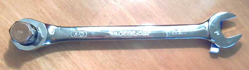
I'd have been happier with, eg, a two inch central diameter - or 3 or 6 - but this was the largest size ratchet wrench in the store. I know those things are pretty darn tough so they won't slip or bust when you're reefing on a nut - but it remains to be seen whether it's tough enough to move a car along the roads, and how long it will last in such an application. (I wonder what the maximum RPM rating of the ratchet is?)
This ratchet has 72 'click' points, so the maximum speed reduction possible is 72:1, ie, 72 turns of the motor will turn the wheel around once - less rocking motion from the motor wouldn't click the ratchet to its next position. Thus it would be "neutral". But at 72:1 reduction the car should climb a really steep hill! Later I sketched out a design using it - or better two of them. One will suffice for an initial test - the car should move. Two will even out the torque better. I think that's what Constantinesco's odd looking piece essentially was: two ratchet arms on a hub.
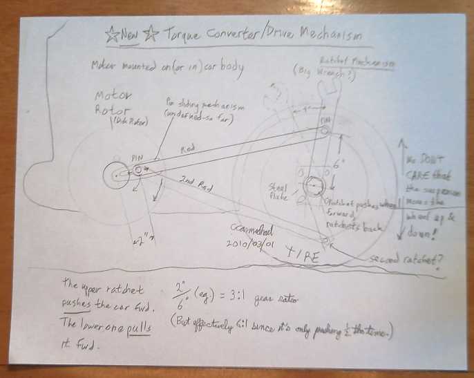
The basic plan.
At first, I didn't like the idea of long horizontal 'reef bars'/rods, which would mean the motor rotor would naturally be offset from the output rotor - the wheel. It seemed an unwarranted departure from everything the motor was about. Perhaps there was some practical way to fold the bars back on themselves? But then I started to think of some major advantages of this "radically" different setup:
1. The connection between the motor and the wheel would be amazingly flexible. There's just the two rods to the two ratchet devices, which could have a ball and socket joint at the wheel end. The wheel could move up and down freely with the suspension, while the motor remained stationary. The rod(s) and the ratchet(s) would move, twist and adjust.
2. The motor could and would be mounted on the body of the car instead of on the wheel: unsprung weight would be limited to the ratchets and mounting plate. Suddenly a few pounds more or less for the motor is no big deal. And the electrical cables wouldn't get flexed with the up-down motion of the wheel over bumps, eliminating any chance they could wear out prematurely.
3. There would be no brackets to mount onto the brake drum housing behind the wheel. This could considerably reduce the installation time and cost, while at the same time, the fewer parts mounted around the car wheel and axle would make the system inherently safer if something came loose, and the tire would be easier to change.
4. Perhaps the motor could be mounted high enough up to be above curbs, eliminating most of the potential for sustaining damage when parking at one. The geometry would vary car to car, partly with wheel diameter.
5. Needing only one spinning rotor and no protruding shaft, the EH motor design becomes more flexible - it could again be made from any old rotors and independent car wheel axles that can be fitted together properly, with no machine lathe turnings.
6. Potentially, any sort of available motor might be mounted inside the car behind the wheel, with the shaft sticking out through the body and the drive mechanism attached outside. The practicality of this idea would depend on individual motor and car geometry and spaces.
A potential disadvantage is that the car body may be too light to mount the motor on without reinforcement. Another is having moving parts out in the open, though that can readily be fixed with a guard over them.
This ratchet mechanism is the output end of things. In that, we have a drive that's better than a gear in that the offset pin on the motor rotor - and-or the ones on the wheel ratchets - can be adjusted, moved in and out to obtain whatever 'gear' ratio seems best. At the input end, the distance of the pin off center determines the turns ratio of motor to wheel, from no motion if it's dead center to a low ratio if it's out by the rim. I can mount a pin at some fixed point and have the motor move the car with good power for a low speed test - that will be, at least, gratifying. The part I haven't figured out yet (in all of two busy days), shown as "undefined" in the drawing, is how to get the spin of the motor to determine the right distance out and hold it there. Some centrifugal device will have to be worked out for that, that moves it outwards as the motor speeds up.
...or it could be done Constantinesco's way, with a pendulum.
A small detail: I don't see any quick way to do reverse gear with stock ratchet wrench(es), because running the motor in reverse will still drive the ratchets forward. I think I just won't have reverse on the first prototype. There's always giant, reversible socket wrenches...
I think this design is going to prove to be a winner!
The ratchet wrenches found for the torque converter are also a better mechanism than the bicycle wheel ratchet gears to link linear cyclic "piston" motion derived from the waves to the generator shaft for the ocean wave power. They'd be linked up with a couple of simple rods instead of the clumsy 'bicycle chains on a stick' piece that I used.
With those, and a lawnmower motor for a great generator with no magnetic cogging, I could do a mechanically superior 'proof of concept' wave power unit. One that would probably even work! Perhaps I'll look for a used electric lawnmower to get the motor from, and revise the wave power unit this summer if I can find the time (and haven't lost too many of the pieces - at least I still have the floats assembly).
February Details
February Thoughts and work
I had occasion to do a bit of study on this subject, and this time I varied my search terms more and came up with a key point in the procedure that I'd missed previously. I now have about three different things I'd like to try with these cores. I also found that saturation flux of .9 to 1.3 Teslas is said to be attainable with microcrystalline cores. I don't have a figure for regular laminates (yet), but I think that's at least comparable.
The first thing to try is the key step I'd missed in making the microcrystalline coil cores. I can try this with cores I've already made. Once the cores have been fired in the kiln and then quenched in water a la rakku pottery, they need to be heated up again to a lower temperature, eg 420-510 ºC, and allowed to cool slowly. In this second, 'annealing', heating, the micro crystals form as it cools, embedded in the overall amorphous glassy structure.
Second, it seems most people are making them in thin, flexible laminate strips. This seems superfluous, assuming the cores are electrical insulators anyway - who then needs them to be laminated? However, it seems they can't be made very thick. When I smashed one of my cores, I noticed that the structure at the surface changed with depth. This is logical as the clay doesn't transmit heat very well, so the deeper volumes cool slowly in spite of the quenching, unlike when quenching a metal.
Instead of making strips, 'solid' cores with lots of little holes for water to pass through during quenching might work okay. Otherwise, I suppose laminated pieces could work fine too. I can address this point later - even if my solid cores just work near the edges, I should be able to measure some effect and know if a formulation is working.
The third item is test measurements. If I had a core that worked a little bit, I may not have noticed it. A slight success can be built on more readily than just continuing to try random things. I needed a better way of testing wherein I could take a simple reading and compare it.
To solve the third problem, I figured out a way to use the first test jig I'd made, in a modified way. With the coil sitting on top of a thin piece (of wood) and the scale placed underneath with a piece of steel on it, the distance between the coil and the steel would be constant, regardless of the exact size of the core, the shrinking of which during drying and firing varies with firing temperature, ingredients mix, and moisture content.
Energizing the coil with a 12 volt battery, using a .5 ohm resistor in series with the coil (max 24 amps), the lift on the piece of steel on the scale is indeed measurable as a decrease in scale weight. Air core reads about 10 grams decrease. The steel laminate core gives 30.
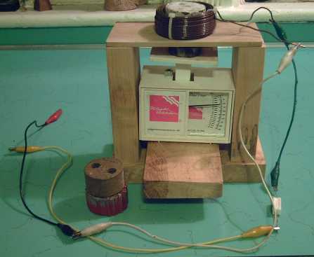
Coil test jig setup
To anneal the cores, I simply have to heat them in the kiln and let them cool with the door closed, since the duration of the heating evidently has little effect. The problem then is to know how long to turn the kiln on for. The temperature is too low to use a pottery cone, but too high for a kitchen oven. I need a 1000ºf thermometer.
On March first, when I went shopping/hunting for grilles for the electric heater, nickel metal for alkaline batteries, a ratchet device for the torque converter and, by the end of the trip, a new muffler for the car, I also managed to get some "type K" (higher temperature) thermocouple wire. I'm hoping I can find somewhere on the web with a table of voltage versus temperature for this common type of thermocouple wire. Otherwise I need to spend $150 on the real 'pyrometer' and test probe (...made of type K thermocouple), instead of $3 for just a yard of wire.
As a final thought, having now, at one point, located a company on the web that makes microcrystalline core strips, I could try to simply order some. Assuming I can find the company again on the web. I'm not sure that will be any more successful than trying to make them has been, because usually such manufacturing companies don't want to talk to someone who only wants enough material to try out a new design, notwithstanding that success with a new design may bring in big orders later.
February Details
February Experiments
In the last week of January I had put together a "ClO4-Mn" battery and started charging it at low current as the first stage of the "burn-in". Following this, like most of my batteries, it didn't seem to hold a charge. It seemed to me I'd put in the right sorts of chemicals, in reasonable proportions. The lead acid batteries had all the right chemicals, but they needed deep cycling to "renew" them. And there are proceedures for "burning in" or "forming" some types of batteries. Perhaps there was similar 'trickery' needed for my own batteries to get them to work?
First I upped the current to around 30mA. Soon the cell had over 5 volts across it. Seemed ridiculous. Then I shorted the cell for a while. It delivered about 5mA. Then I charged again and it didn't seem to do much differently. Then I reversed the polarity. I expected the voltage to start at some value and work its way up. Instead it quickly reached (-) 3-1/2 volts and worked its way down, at first quickly and then gradually (seconds, minutes) to 1.9 volts. That's about the voltage it should have risen to and stopped at when connected the other way around! However, it doesn't stay near that voltage a moment when the charge is removed.
None of this seemed to provide a solution.
Sigh! To break the impasse of a great chemistry that I can't get to work properly, I'm considering making at least a demo Ni-Mn alkaline cell. At least for alkaline I think I now have the essentials worked out to make good working cells. The last missing piece was the gums to hold the briquettes together. Ni-Mn alkaline should hopefully at least be better than Ni-MH, by about 66-75%, owing to it being around 1.8 volts/cell and perhaps 3/4 WH/g, instead of 1.2 volts and 1/2 WH/g.
Gas pressure may be an issue. In fact, I think I'd better vent it - caustic lye spraying one in the face if there's a leak would mean blindness! The higher the voltage, the more oxygen and hydrogen are made from the water. That's why lead-acid batteries (2.0V cells) are usually vented. (I also expected lower pressures from the perchlorate chemistry in spite of the voltage owing to higher current capacity, resulting in reduced charging voltage, eg, 2.1V to charge 2.0V cells rather than, eg, 2.3 to 2.4V with lead-acid.)
For the positrodes I'll have to switch to pure nickel sheet metal instead of nickel-brass, nickel powder instead of monel powder, nickel mesh instead of stainless steel, and nickel bolts, if they exist, instead of stainless for the terminal posts. The negatrodes can be the more ordinary materials - it's the anodic oxidation during charging plus the strongly alkaline environment that seems to corrode everything except nickel.
Whether I try making it or not may depend on whether I can get some pure nickel products without mortgaging my house. With nickel rod, I can grind it to make enough powder for a cell or two, and I can pound and thread the rod to form the positive terminal bolt. With a good mesh to conduct across the electrode, it doesn't really need a nickel plate backing - paper or plastic should work. That just leaves mesh... Hmm, it seems a nickel mesh is 'available' for screen printing, but nobody actually carries it. A supplier in Vancouver thought he might be able to get some in, but he didn't call back. Likewise, nickel welding rods are 'available', but are a special order of about $400.
Someone told me that electroplaters use nickel 'shot', but a trip to Victoria Plating disclosed that it's purchased in bulk and the entire load is dumped straight into the plating vats. They gave me one little piece that had somehow escaped. Well, I can grind that into a little powder!
Otherwise, most of these nickel products are probably special order from separate USA companies (even Inco's nickel powder has to be ordered from the US, notwithstanding Inco being in Sudbury, Ontario), and most companies will ship only by couriers with their border piracy. ...This could be a pricey thing to gear up for!
I had considered that there appeared to be just two ways to connect the electodes to the terminals, in particular the positive side, given that solder would corrode away: Bolts made of something that wouldn't corrode (hopefully stainless steel with salt electrolyte - nickel for alkaline cells), or welding. Bolts are tedious and can come loose; spot welding is not amenable to small scale, minimal investment manufacture.
As an example of the power of the corrosive power of the 'positrode', I used a #4 plain coated nut and bolt in the present battery. I took it apart weeks later and found half the nut, corroded away and fallen down, and none of the bolt at all. (though perhaps some remainder fell to the bottom once the nut was gone - I didn't check there.)
But now I've thought of another connection technique: riveting. Stainless steel rivets should work as well as stainless steel nuts and bolts. Perhaps I'll try this next time. Nickel rivets if I have to make alkaline cells... and if there is such a thing.
February Details