I started March having just conceived of what at first glance looked like a great new way of doing a torque converter, but after a couple of weeks working on part of it, I started realizing it would have worse vibration problems than my previous design unless it was made with some pretty complex parts. And the way I was doing it before, though using some obscure mechanical clock principles, was theoretically better as far as I could tell. So I switched back and finished it. Some long overdue home maintenance then used up most of the last week of March and I didn't get past a bench test.
But the part I had made for the discarded new idea could instead be the main push-bar, arm and ratchet assembly for an improved version of the ocean wave power machine, tying the wave power capture floats to the primary rotating shaft. I also got a lawnmower motor to use as a generator for that, so the work and parts won't go to waste - assuming I find time to put together and test the upgraded wave power unit.
I also plugged away at finding out more about nanocrystalline magnetic cores. The crystals are smaller than "micro", and using "nano-" as the search term turned up far more info! (...not a real "recipe book", though.)
And I plugged away too at finding nickel mesh and other nickel materials to try making alkaline batteries. It seems astounding that such a common metal should be so amazingly hard or costly to actually buy. Finally I came up with a plan to use the working electrodes from old dead (shorted) Ni-Cd/alkaline batteries to test one new component or idea at a time. The perchlorate battery might all be working except one or two details, but I can't isolate the problem(s) as to which electrode or process.
Looking back after 27 months on the Electric Hubcap project, it has taken far longer to get this far than I ever expected. An impartial observer might suggest that the project is anywhere from 6 to 15 months behind where it "ought" to be -- depending on what I could be supposed to have known or had figured out before I started.
But inventing is about doing things no one has done before - uncharted things, and in spite of being a one starving inventor operation, look what has been accomplished!
* The only effective 5-1/2 HP permanent magnet 'pancake' motor that anyone can make at home.
* A matching 3-phase solid state motor controller that's an easy electronics project.
* Comprehensive plans for making both of these are on the web for anyone, anywhere to use.
* A mechanical torque converter ("MTC") is in the works, to replace entire automotive transmissions with a light, efficient "CVT" type of unit.
* When the MTC is completed, these will bring a practical means to turn any car economically into a plug-in hybrid - an electrically ultra-efficient one needing less horsepower and energy.
* Plans for an electric fan-heater on the web for home construction (okay... not much of an 'invention'!)
* Some valuable car installation techniques have been worked out for the add-on drive system.
* Designs for electrodes, jigs and cases that will make it practical to make batteries at home.
* The only current portable battery new chemistry & fabrication research besides pricey lithiums. (AFAIK)
* Two possible high-energy battery chemistries have been uncovered: One uses techniques of ion chelation never before tried in batteries. The other promises higher voltage, higher energy alkaline batteries.
* I've disclosed that lead-acid batteries can be treated to last far longer or can be rejuvenated with sodium sulfate salt. (A fact the battery industry has kept hidden from the public for at least 70 years. I also have some sodium sulfate for sale since I found it hard to get and had to order a 30 Kg bag of it!)
I've just learned a new term, Scope Creep. It's the tendency of a project to keep growing in scope from the original intent.
An inventive project is especially susceptible to this, partly of necessity, and the Electric Hubcap project has certainly acquired a lot of it!
The original seemingly simple plan was to use a version of the pancake shaped generator of the wave power machine as a pancake motor to attach to a car wheel. But that, in addition to becoming an almost complete redesign in itself, necessitated creating an unknown (to me) type of solid state motor controller - easily doubling the project's scope, even for an experienced electronic circuit design guy like me. The motor and controller are finished, first working in 2008. (improved components and techniques keep popping up now and then, though - necessitating frequent revisions to the manuals!) But hybridized cars aren't rolling down the street on electric power.
The components naturally needed proper installing on the wheel and in the car, with connections to the gas pedal and a switch for Off-Reverse-Forward up at the front of the car. And re-plugging the fuses so the signal lights work with the key on "ACC". (Even now activating the system isn't tied into turning the car key, though the provisions are in place... except for my car key's "ACC" contact not working. That's right, the car radio doesn't work either!)
The October 2008 car move test - though the car did move - showed that hooking the motor straight to the wheel wasn't really practical. The RPM of a car wheel at low speed is just too low, even for a lower RPM motor. (...now if a car's tires were 10 inches in diameter...) I could perhaps have used planetary gears to make a compact transmission, but the better solution seemed to be some sort of highly efficient torque converter or CVT. Some new design of magnetic or mechanical torque converter seemed to offer the best prospect - but it was (is) another big piece of scope creep.
Then there was the realization that running the car with the gas engine off would require an electric fan-heater (at least to defog the windshield!) and an electric vacuum assist pump because car brakes are made to need vacuum assist. I tried to buy a heater but they never shipped it, so I made a better one. I have yet to install it or a pump - more scope creep!
Early on, looking for batteries for the motor disclosed that since the successful electric cars made in the late 1990's, Chevron had put Ni-MH batteries under lock and key and isn't about to let anybody make any more big enough for electric cars, ever; that lead-acid batteries were heavy and didn't (seem to) last very long; and that lithiums were uneconomically expensive. So I decided to try making batteries, hopefully better ones - Major Scope Creep!
Looking for an easier way to manufacture the motor coils, I ran across "microcrystalline ceramic" cores that were supposed to be very good and would make the motors still more efficient. So without knowing much about them but having enough ceramics skills to be dangerous and my own mini-kiln, I decided to try making those... more scope creep!
And finally I discovered that certain sulfate salts could greatly extend the life of lead-acid batteries, so, having so far made no practical working batteries myself, I started looking into that. I uncovered that they're used in long-life golf cart batteries, and that prototype Interstate Optima batteries with sodium sulfate lasted 5 years of daily EV use instead of "the usual" 1 to 1-1/2 years. But though it has its practical advantages, perhaps even for Electric Hubcap drive systems... here it's more Scope Creep!
March Details
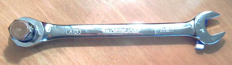
As hinted at last month, March opened with a plan for a "radically different" drive motor configuration. On the first, a critical part was found: a ratcheting lever that would turn the car wheel in one direction when pushed, but simply click back when pulled. This would permit an off-center pin on the motor rotor to drive the wheel via a rod and the lever. A centrifugal device setting that pin's distance from the center based on the motor RPM would then constitute it a variable ratio torque converter.
By the fourth, an attachment plate for the car wheel had been made and the mechanism was tested by standing on the lever and moving the car. Nothing busted. It seemed good enough at least for a prototype.
But with long linkage rods required, the motor would have to be mounted next to the car wheel, preferably above it, instead of on the wheel as per all previous plans. But that should actually have some advantages!
By the middle of the month, work was progressing well, but a sudden realization came that there were serious problems with the design. It was abandoned and I went back to working on the previous, "rotary" design.
The main work that hadn't been done was to mount magnets on the drum rotor. To do that needed a new jig for 12 equally spaced magnets at 300mm diameter, to replace the previous 18 magnet jig. I modified the jig:
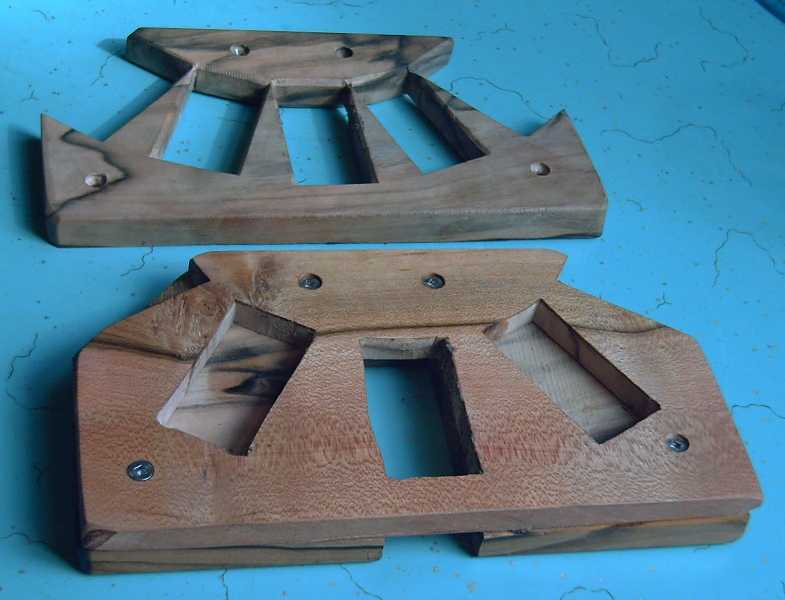
Top: old jig piece for 18 equally spaced magnets.
Bottom: revised jig for 12.
Gluing the magnets onto the drum rotor.
The second six kept trying to flip over as I tried to get them into the hole.
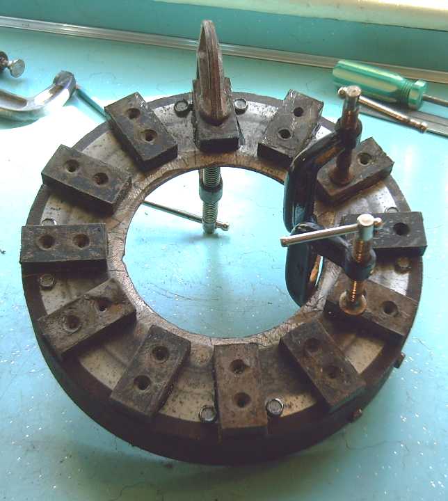
Got them all. (no fingers lost!)
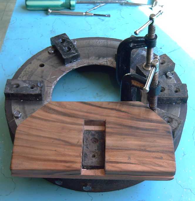
The plate bolted to the car wheel.
The pins from the torque converter inertia plate fit into the four empty holes for a flexible coupling to the wheel.
I decided to make another motor controller. I have no particular need for a second controller, but I wanted to improve the layout, and the instructions in the manual, and also see if I could clean up the heatsink area somewhat. I may make it 24 volts instead of 36 - which just means a few power components with different specs.
Previously the wiring and components on the heatsinks looked a bit like this:

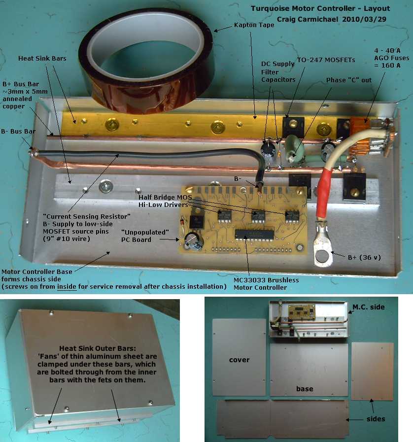
Tho it's unfinished, the likelihood of achieving a much neater job seems evident
An interesting thought came to light: I had been puzzled that the leeds on my filter capacitors had been "burned off", while the capacitors themselves looked intact. Usually the capacitors pop aprt if there's a problem and the leeds are fine.
In fact, I had been using some lead-free solder that I later found was causing serious corrosion problems. (Rather, its flux was.) It's likely that I used that solder - the breaks happened at or near the solder joints - and so the problem wasn't electrical at all. That means I probably don't need these oversize 200 volt capacitors in this 36 volt circuit. I've gone back to much smaller smaller 100 volt components. That also will help make it tidier.
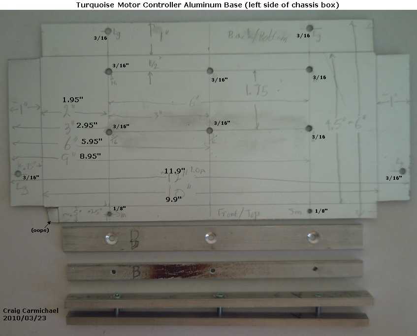
This is part of my idea of improved documentation for the manual - the actual aluminum motor controller base pieces, cut and drilled, with dimensions, as seen finished in the previous image. Of course, I neglected to account for the thickness of the other metal pieces in the written dimensions (and the actual piece), so I typed revised dimensions into the image. Maybe next time I'll just go for typed, which can be changed without a trace just by starting again with the raw image.
36 V Supply and Dangerous Voltages
On testing the electric car heater and working with the wiring inside it, clipping on test leads and measuring voltages and currents, at times I was nonchalantly touching the supply voltage, and I thought, yes, it is a really good idea for the main supply to be only 36 volts when DIYers will be doing these sorts of things! Even 48 would be getting up there, and 30 or 24 volts would be even better. 144 or 300 volts DC for electric car systems is madness - and worse in a "DIY" system!
It took me some time to get out the trap of thinking that because the car companies were using high voltages, that must be the way to go. The car companies probably started it in ignorance themselves, the systems being initially designed by electricians familiar with line voltage motors in buildings, running on the power grid. Those are generally in dry, heated locations, and the connections to the power are very long. The wiring would be very costly if thick wires for high amperages were needed. The fat wires needed in cars only run a few feet. (and fat car battery cables can be had "used" at an auto wreckers, too.)
Electrically savvy types on the DIY_EV_Cars@yahoogroups.com list keep haranguing me when I warn some newcomer about the dangers of higher voltages, and reiterate that motors of any size can be made for any voltage and will perform exactly the same. They seem not to realize that not everyone has the same experience they have working with dangerous voltages, and that an amateur DIYer who isn't an electrician designing his own electric car system, is in much more danger than a cautious professional who knows all the angles and safety precautions in advance. (...who is nonetheless making a dangerous and needless hazard for himself just to save a few dollars of copper.)
The only reasons for using higher voltages are: (1) if the required kilwatts would result in absurdly fat cables that are hard to work with. (2) if a surplus motor is available that is already made for a higher voltage. The Electric Hubcap system partly addresses both these issues, first by being a 5+ HP, 36 V motor than can be easily and cheaply made at home, and second by needing less power to move a vehicle. (I keep thinking I should make a 24 V EH motor just to show it will work the same as the 36 V one.)
The electric heater works nicely. I've posted the plans for making it on the Turquoise Energy website at: http://www.TurquoiseEnergy.com/hybridize/heater/DC-Elec-Heater-Plans.html so I won't go into construction details in this newsletter.
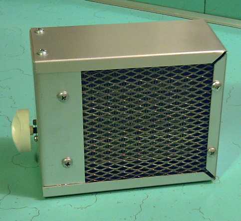
The assembled heater, minus its mounting. The switch side (left) is the bottom.
Mechanical Torque
Converter Project:
Torque Leverage Without Gears
March Details
Torque Leverage Without Gears
March Details
After figuring out what seemed like a much more certain-to-work design for a mechanical torque converter that would have much less noise and vibration, I abandoned the half-made one and drew up a list of items that would have to be completed.
1. Make a plate for the car wheel with the hex nut or bolt head at the center.
2. Make a mounting for the motor and mount it on the side of the car near the wheel.
3. Make a bar and both end fittings to connect the ratchet (wheel) to the offset pin (motor).
4. Make a centrifugal device to adjust the offset of the pin from the center of the motor,
based on the RPM of the motor.
5. Toss the wrench(es) and get something that could provide a reverse gear.
6. Make and install covers for the moving parts and the motor.
7. Tidy up, get rid of old fittings, re-route motor cables, etc.
Once items one to three were complete, the car could be tested in a big parking lot or on a quiet street. The speed reduction ratio would have to be set to give it sufficient starting torque to get up speed in reasonable time, yet not overrev the motor at too low a speed. (Of course, there's no "too low" a speed in a first proof test!)
A four to one ratio would probably allow the car to get moving on level pavement, and in theory get up to 50 Km/Hr. Ten to one would let it start up a good hill, but the car would only reach 20 Km/Hr. The minimum ratio, two to one, would allow 100 Km/Hr... if the car would start moving, by no means a sure thing.
One
The first item was done by March 4th, and it was also tested that day: I attached the plate to the wheel, and moved the car by standing on the end of the ratchet wrench. When the end of the wrench sank down as the car moved, I lifted it, ratcheting it back to horizontal, and gradually moved the car over several feet of eneven gravel, including uphill. This test proved that the plate and nut, and the wrench, were all at least nominally strong enough to not bust right away with the torque needed to move the car.
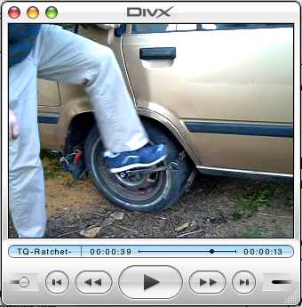
Moving the car by stepping on the ratchet wrench
(I didn't post the movie since this technique won't be employed - if anybody wants it, please ask. 3.6 MB)
Total addition to unsprung weight will be around 1.5 Kg: the plate with bolts and nuts, and the inner ends of two ratchet wrenches.
This is a marvel -- mounting the motor off the wheel solves all the problems of adding unsprung weight to the wheel. You probably add as much when you go from old worn tires to new ones with good tread!
Interestingly, the Constantinesco torque converter speaks of "mechanical valves", which term I don't understand the meaning of and was unable to find a fitting definition or explanation for. "Valves" is the British word for vacuum tubes. In context, that probably would imply vacuum tube diodes. But the text mentions ratchets as an alternative - used in the "Meccano set" model version, the effect appears to be the same:
"This example follows the same arrangement as in fig. 18, but ratchets had to be used as it was not possible to construct mechanical valves with Meccano parts."
However, in the search I located a catalog: "Morse/Browning Clutches and Torque Overload Devices". I suspect the problem is mainly one of nomenclature - what do you call such things? "Rotary diodes?" Some of them do have one way stopping, the other way slipping, as desired. I suspect some of the mechanisms are much superior to a simple ratchet. (The catalog has a lot of confusing choices... perhaps I should make the one with the wrench, run the car, then show them the movie and see which model they recommend!)
One choice I didn't see (at a glance) are any that can be put into reverse.
Two
I decided to mount the motor above the wheel instead of behind it. There didn't seem to be much room back there, and above there was an adequate area... and it was certain never to hit any curbs while I was parking. (Another advantage of mounting the motor off the wheel.) Here, however, it would stick out farther, and the bars to the wheel would have to have bends in them below the car fender to line up right and still push, in by the wheel. The ratchet wrenches would also move around a lot more with bumps as the wheel moved up and down. So what? In fact, the weight of the bars and ratchets will be held more by the car than by the wheel, minimizing the effective "unsprung" weight.
Looking at a few cars in a parking lot, it appears none have much room near the wheel and each one will need mounting in its own best place. But now considering unsprung weight, straight above should actually be the ideal place.
The motor mounting brackets were made by the 10th. I figured out a couple of good new techniques for bending steel bars in the process. Also I got the inside trim removed from the car to access the inside of the body metal and see where best to drill mounting holes, and I pulled out the cables to the wheel and the motor controller to reposition everything. Although this is the rear 'roll bar' area, there's nothing but sheet metal to attach the motor to. Oh well... brackets and big washers!
Then on the 12th, I decided to turn the motor around and have the rotor face out instead of in. It would be a great advantage to have access to the rotor without dismounting the motor for prototyping the motor end of the torque converter. So much for the new mounting brackets!
The 11th started with rain, and I started giving consideration to how the link rod would attach at each end. I found a ball bearing race left over from the wave power machine that was a little bigger than the 1" wrench open end, with a 1/2" interior... for a 1/2" bolt. If I ground out the open end end of the wrench right, it could be gripped in there and could only come out the sides. With the bolt inserted through a forked end on the bar, it would all be held together. Presto! There's one end with ball bearings. I ground out the wrench and cut the fork pieces on the 12th, but I didn't get them welded. (I also ran two tests on a lead-acid battery, added sodium sulfate to it, re-fired my core pieces in the kiln, improved the cores test jig, and wrote again to try to order nickel mesh for alkaline batteries.)
Whether it's a big enough bearing race to last reliably for extended travel, I'm not going to try to answer. Some of the parts could last anywhere from 50 meters to 50 megameters. I'll hope for closer to the latter figure in all cases. Any that prove closer to the former will have to be up-sized.
Three... strikes and you're out!
I felt it was inevitable that the offset drive pin on the motor would have to have ball bearing connections to the drive bars to the wheel. Failing bushings with oil being pumped through, nothing else would take the strain of moving a car for too long.
On the 15th, I welded together the rod end pieces and made the ball bearing joint of the ratchet arm with the rod from the motor. Everything seemed to be proceeding smoothly.
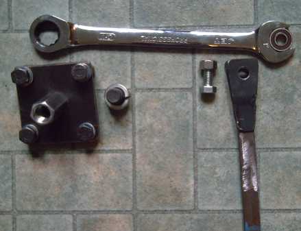
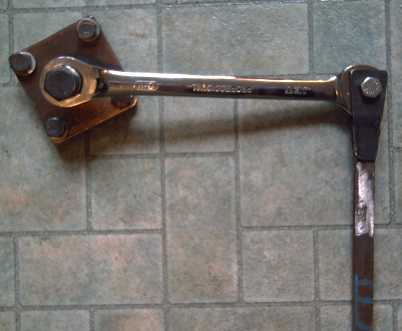
Wheel plate, ratchet device with arm (AKA wrench), having a ball bearing race securely gripped, and link bar to motor.
I noted that the weight of the completed assembly was significant. Suddenly I realized the whole mechanism wasn't going to work! If everything was mounted on a solid frame, it would work. But the car wheel is on springs. With the motor mounted on the car body and links to the wheel, any non-symmetrical forces such as would be created would act to make the suspension jump around instead of turning the wheel, simply shaking the whole car! Oops! One could push the wheel horizontally from front or rear and the degree of the problem would be greatly lessened, but it would still exist. It seemed the only way to apply non-symmetrical force from the car to turn the wheel would be through something like a drive shaft. That would mean gears and losses.
In the next few days I thought of a couple of other features of the design that would cause problems. First, the off-center pin would create imbalance and unbalanced forces in the motor. That itself would cause a lot of vibration. It might well be worse than my rotary design.
There are ways to make all the forces symmetrical and to keep the motor balanced, but the whole thing starts to get complicated with specially cast parts and double pins, rods and levers going opposite ways. Constantinesco's last, most complex looking design appears to have these sorts of balancing features. These then become even more complex to make centrifugal as I'd envisioned. One of the goals of this project is components that can be made at home or in small shops rather than in a foundry, or special factory.
Another consideration is that the push rod plus arm to the ratchet assembly weighed quite a bit, and they were to be pushed back and forth. That would be fine at low speeds, but like a clock mechanism, wouldn't it take a lot of energy to move the mechanism at higher speeds - motor and car speeds? Especially if they were all doubled up for balance? If they were a lot lighter, they might bend. The losses could be much worse than the minor frictional losses that might be expected in the rotary prototype. The only part being shifted in the rotary design is the inertia plate, which is the active motion that governs the amount of thrust transfered to the wheel at any given speed.
My lack of interest in the finer points of mechanical engineering shows in not thinking of these details sooner. I guess I'd rather be designing circuits or writing software. So after two weeks, I decided I'd best go back to my rotary design. (Too bad I ripped out the motor controller and the wires to the motor because I had intended to move the motor to a new position! I also ripped off some plastic interior from the side wall of the car. Sigh! At least I didn't get around to removing the main motor mounting brackets on the wheel, and I bought a new piece rather than cannibalize the original motor straps to make the new ones, saying "I'll keep these just in case...". And I didn't quite get to drilling the holes through the side of the car!)
But much of the effort was not wasted. The rod, arm and ratchet piece is a perfect fit for an improved proof-of-concept ocean wave power unit.
Also, the idea of balancing the forces could be applied to the rotary design. One could conceivably have two rotating inertia plates instead of one, with opposite slots in the rim of the drum rotor. As they would move oppositely, their movements tending to cause vibration would cancel, viz:
________ ________
____/ \________/ \____
____ ________ ____
\________/ \________/
Other parameters that may well want adjustments are the slope and the shape of the slot ramps, and the actual weight of the inertia rotor plate(s). These will affect how hard the motor is worked to produce a given impulse to the car wheel and how much noise it will make. A curving ramp layout might make almost no noise, viz:
(
)
(
)
(
)
(
)
whereas the flat 45 degree slopes were very noisy and loaded the motor heavily. I cut that slope in half for clockwise (forward drive), which remains to be tested. I think the main problem with the curving ramp layout is that it's harder to fabricate. Not impossible, though! I suspect the first one will be so noisy that I'll have every incentive to do a curved slot.
On the 17th I trimmed a few things up and made ready to put the magnets on the drum rotor. Since the rotor ramps were removed, I ground the entry to the counterclockwise (backing up) ramps into a shallow curve. I'll be able to compare forward to reverse - especially if the car actually moves. But once moving sideways, the plate will still hit the end stops full tilt.
On the 18th I drilled holes in a plate to mount on and turn the wheel. This plate needed two sets of four holes, one set to bolt to the car wheel nuts and the other for the link pins on the inertia plate that drives the wheel. (One set was already drilled because this plate was the center piece cut out of the brake drum.)
As previously mentioned, the connection of the link pins to the plate forms a flexible coupling that greatly reduces the effect of the weight of the motor assembly on the wheel as the car hits bumps in the road.
The 19th saw the magnet installing jig finally changed to what I've wanted for a year: 12 evenly spaced magnets. I might like to experiment with other magnet spacings and/or other sizes of magnets that might tweak maximum performance or low speed torque a bit, but quite aside from magnetic considerations, the 12 of the 1 x 2 x .5 inch size magnets with even spacings makes a pretty good coil cooling fan. (At the moment, not much air is blowing out, though -- in the present setup there are no holes for the air to enter at the center.)
Next the 12 magnets were glued onto the torque converter's drum rotor. (See EH - Vehicle Drive System for photos.) With house maintenance intervening for a week, the motor was finally tested with the magnetized drum rotor on the 28th. It ran great. (Why wouldn't it?)
On the 31st, I clamped it down properly to the bench and made a lever arm to hold the torque converter back with. Certainly there is force there. The question is, is it enough force to move a car? Since the force is in little pulses, each of which *should* be strong enough, the question should boil down to whether the car will start to move in small increments, or simply go back to where it was after each pulse - sit there and vibrate. I can hold the lever from turning because my arm moves a bit during the pulse, then pushes it back between pulses that little bit - thus my vibrating arm holds back the *average* torque rather than the max.
Here is a movie of the bench testing (click image, 5.7 MB AVI):
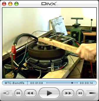
If it still doesn't work, there is one easy thing to try: remove two of the four 'strike' pins from the inertia plate and half the ramps from the drum. Then there will be just four torque pulses per revolution instead of eight (two pulses up, two down), and they can be made twice as strong, eg, just because the motor would run faster, or else by steepening the ramps.
A final thought for the month: People have asked me if the converter will lock to 1:1 with the wheel when cruising. I've said that if the converter is as efficient as it should be, it doesn't matter a lot whether it locks or not.
However, I've thought of a way. Put in a spring that pushes the inertia plate to one side, to the "bottom". Not so hard a spring that it can prevent the motor from starting to turn if it's stopped at the ramps, but anything short of that.
Then if the torque isn't high enough, the pins will hit the ramps and not go up them -- 1:1 direct drive. (No noise, no vibration except when starting from a stop or accelerating!)
A spring would also eliminate the need for having upper ramps at all. (It has to be strong enough to pull the inertia plate back to base before the next ramp at maximum RPM. I don't think this is exclusive to not preventing the motor from starting.) In fact, having spring return and no upper ramps would cut the number of torque hits in half even retaining the four lower ramps, again allowing stronger hits. Say! It would also simplify construction of curved ramps - there'd be no upper side to the "slot"! This seems like a very promising line of development.
This month I learned that the size of the crystals at issue is "nano" - or tens of nanos - rather than "micro" - which would be 100 times longer and a million times larger by volume. Searches on "nanocrystalline" thus yielded far better info than previous searches on "microcrystalline".
A good question is, what advantages do nanocrystalline ceramic cores have over the iron alloy motor core laminates everybody's been using for over a century? A second question arises from the answers to the first: if they're better, why aren't the major motor companies switching?
At first, I was mainly attracted to the idea they might make the motor coils really simple to make. It looks like the fabrication will be more complex than expected (still quite doable), but other excellent reasons have come to light.
The first question has three main answers:
Three main things keep efficiencies low enough that motor cooling is very important:
* electrical wire resistance losses ("copper losses"). The core material has no effect on this.
* magnetic core material hysteresis losses. The magnetism in the electromagnet coils reverses as the motor turns. This means repeatedly discharging the residual other-direction magnetism that's left over. Alloys are chosen so they won't hold a magnetic charge (opposite to permanent magnet materials), but with regular metallic alloys containing magnetic materials, the magnetic charge holding is always greater than zero, and some of the electricity going into the motor is used up reversing it.
Because the crystals in the nanocrystalline ceramics/composites are so small and are not physically touching each other, they won't hold a magnetic orientation: they demagnetize spontaneously. Therefore the magnetic hysteresis losses are very small.
* eddy current losses. The magnetism going by from the rotor magnetism induces electrical currents into the core material - generating power into a short circuit. Regular laminates are used to "dam the river" with one little dam after another to prevent the electrons from flowing freely. When the cores are electrically conducting alloys, this technique is not 100% successful.
Nanocomposite materials are insulators - virtually no eddy currents can flow.
("Slip loss" of induction motors doesn't apply in a permanent magnet motor such as the Electric Hubcap.)
Thus, the main motor losses except copper losses are reduced to near insignificance and higher efficiencies can be obtained. A 92% efficient motor is only a little stronger than an 84% for "x" watts input, but it generates only half as much internal heat that has to be dissipated. (This is especially significant if it allows turning "liquid cooled" into simple "fan cooled".)
Surprising as it seems, and quite unlike ferrites, the maximum magnetic field before saturation is higher for the nanocomposites than for solid metal - .9 to 1.2 Teslas. (Sorry, I have no figures for the metal, but it's said to be lower.) It might be possible for motor coils to develop "supermagnet strength" magnetic fields similar to the supermagnets they are driving.
That means the motor can develop a higher torque. It's still doubtful whether a motor of the EH size range could develop enough torque directly connected to the wheel to start a car moving uphill. And even more unlikely it would do so without also developing "burning out" levels of heat in adverse driving conditions. Higher torque would however mean that the mechanical torque converter could "latch up" for 1:1 drive at higher torque levels.
The weight of the nine coil cores is reduced from around 2520 grams with steel to around 900 - that's a 3-1/2 pound reduction in total motor/torque converter weight, 7% off of 50 pounds.
It seems to me that some ferrite inductor cores aren't attracted to magnets at all. When I noted this, it struck me as surprising, since their whole purpose is to carry a magnetic field. I could be entirely wrong about this observation of years ago. The one and only piece of ferrite I have now is slightly attracted to magnets. Of course, possibly it could also be only a marginally effective core material. But if it is true that a material that isn't attracted to magnets can conduct a magnetic field, it could also be the case for nanocrystalline ceramics. Certainly my failed cores mostly are unattracted... of course, they're also failures. But If it's possible to have such a thing (a big IF), this would give rise to two major advantages:
* The components would be easier and safer to handle. Anyone who has tried to put a permanent magnet motor together or take one apart knows how hard it is to pull the rotor out and how it pulls itself back in. The difficulty - and danger - increases once supermagnets are brought into the picture. For the Electric Hubcap, the stator and rotor have to be brought together and forced apart by an inch or more with bolts. Failure to do it properly could result in very serious finger and hand injuries. (At least it can be done without special equipment - I don't see how it could be on radial flux supermagnet motors!) An inch of non-attracting coil materials, or weakly attracting materials, between the stator backing steel and the rotor magnets would be a great improvement.
* There would be no cogging. "Cogging" is the magnetic grip holding onto the rotor as the rotor magnets line up with the core iron in the stator coils. It causes the rotor to align to certain positions when it stops, and there's a breakaway force needed to overcome the cogging before the motor will start to turn. It also causes some vibration, and the pull between the rotor and stator causes extra load on the ball bearings between rotor and stator.
In a motor, the cogging can pretty much be ignored. (Greased bearings last for ages anyway, and there are other things causing more vibration.)
But in a unit used as a generator, it causes a minimum threshold of wind speed, wave height or whatever before the unit will overcome the cogging and start to turn. This leads to non-cogging air core generator designs that use more materials, poorly utilized, to achieve the desired power, raising the price for alternative energy. Non-attracting, non-cogging nanocrystalline cores - IF they are possible - would greatly improve the situation.
The second question was: Why aren't main-line motor manufacturers using it?
The way motors are usually made, the alloy laminates are a major structural component of the motor. Look at a car alternator: The laminates make up the body and give it its form. They hold the end bells apart. Where an outer shell is used, they must be securely attached to it, and that would be hard with ceramics, especially as the coefficient of expansion would probably be different from the shell. To use a material that might be subject to breakage would be a nuisance and probably a safety hazard.
Additionally, the finished dimensions of ceramics are hard to control to the degree of accuracy required. The clay shrinks as it dries, and it shrinks more when it's fired. The usual gaps between stator and rotor are measured in 100ths of an inch, and the ceramic dimensions are likely to vary by considerably more than the gap.
To put it more simply, with typical motor construction, using nanocomposite ceramics would be a great headache.
This is a big advantage of the Electric Hubcap motor design. The coils are made separately and simply bolted to the stator backing plate. Whatever works best is only relevant to the individual coil design, not to the motor design as a whole. The EH's huge 3/8" air gap between the coils and the supermagnets makes minor dimensional variance unimportant.
Another answer to the question might be that it's all too new and there are too many different directions, materials and formulations being followed. The options are still confusing.
Still, if one finds a practical way to produce the nanocrystalline structure, it would appear it's easily adopted on the axial flux machine but difficult to employ on traditional radial flux, hence motor makers might have to do a lot of rethinking about what goes into making a motor - the sort of rethinking that's gone into the Electric Hubcap.
In February and early March I did a little reading on this subject. I finally realized there were two quite different categories of microcrystalline or nanocrystalline materials: the ceramics with metallic glasses, "metglass", and also alloys. The alloys would of course be electrically conductive and would need to be formed into insulated laminate strips like other metal cores. The ceramics, also called "microcomposities", are insulators, and it seems to me they should, all else being equal, perform better simply by having virtually zero losses from electron flows.
But the gains may be greater than just zero eddy currents. One web site about "nanocomposites", says: "A completely new phenomenon has been observed when reducing the particle size and the separation between neighboring particles into a nanometer scale in composite matters. For example, it has been found that a Co- or Fe-based nanocomposite can possess a permeability much higher than that obtainable from the bulk Co or Fe metal. This large enhancement in permeability is due to the exchange coupling effect. The exchange interaction which leads to magnetic ordering within a grain also extends out to neighboring environments within a characteristic distance, the so-called exchange length Lex. Thus, neighboring grains separated by distances shorter than Lex can be magnetically coupled by exchange interaction. For a traditional powder material of large particle sizes, exchange coupling effect is negligibly small in determining magnetic properties. However, when the particle size plus the separation between particles is reduced to approximately Lex, intergrain exchange coupling plays a dominant role and the material will possess a variety of properties different from the bulk size material. One important effect is the cancellation of the magnetic anisotropy of individual nanoparticles: when the particle-particle separation is significantly less than Lex, the intergrain exchange interaction makes all the neighboring particles coupled. This coupling averages out the magnetic anisotropy of individual nanoparticles. As a consequence, the permeability of an exchange-coupled nanocomposite can be even much higher than the permeability of its bulk counterpart."
I also saw sites listing actual strengths of .9 to 1.2 Teslas for some of these materials. Perhaps we may after all be able to obtain electromagnetic fields in a motor stator on the same order of strength as the supermagnets on the rotor?
Notwithstanding the ever increasing difficulty of finding anything uncommon on the web, I located and e-mailed a couple of places making strips of the alloys in order to get some - one in USA (didn't return my e-mail) and one in China - but no luck. They probably can't be bothered if it doesn't look like you'll imminently order an industrial quantity. Too bad for me perhaps, but too bad for them, since being listed as the supply source for a superior material in the Electric Hubcap motor plans would be very good free advertising and, if the price were economical, would probably bring multiple big orders later as the motors gain popularity. I won't dwell long on suppliers of unobtainable materials.
So much for trying to offload even this one project, and back to trying to make the microcrystalline ceramics! I realized the problem is (presumably) more in my methods than in my materials. If I can get them to work, cheap clay cores might allow me to thumb my nose at the alloy suppliers.
First, the ceramic has to be fired and then quenched (dumped into water) to cool it quickly. This creates an amorphous, glassy structure because crystals don't have time to grow as it cools. This I was doing except for my first few attempts, but I was making whole solid cores. Ceramic conducts heat poorly, unlike metal, so only near the surface would they cool quickly. It would seem they need to be made as thin laminates. However, being electrical insulators, the laminations are only needed for the quenching - perhaps they can run any direction regardless of the direction of magnetic field motion. That would mean they could each be a complete thin cross section of the core, built up to whatever height is desired, in this case one inch. unless each minute gap interferes with the magnetic circuit, in which case they would better be vertically oriented.
I tried to slice one of my current cores, #14, into thin strips with a zip disk on the angle grinder, but I got a mess of broken pieces. Bowing to the inevitable, I broke #21 apart with a hammer. I re-fired and re-quenched the pieces to re-test the same cores after proper processing. Then to anneal them, I reheated them to 430c and allowed them to cool slowly.
Next was a magnetic strength test using the test setup mentioned last month that lifts a steel piece on a scale. First was a calibration with air (-4 grams) and then with the steel core (-17). Next I dumped all the pieces of #14 into the coil and tried again (-6). #21 also gave -6 grams. However, these figures are very approximate on a spring scale with 10 grams per division, and I wasn't sure they weren't just minor discrepancies. (I spent $45 on a 100th of a gram electronic scale but it turned out to be a lemon. Not only does it need to be banged and cajoled into turning on, it then keeps shutting itself off, at least once per minute, right while you're trying to use it. Ugh! Its name, "snake eyes scale", should have warned me it was a losing dice roll. I have to go out again and try to find one that actually works.)
I re-heated the two sets of pieces to 490c to see if a higher annealing temperature would make any improvement. This was hotter than I'd planned and near the upper limit - I hadn't stuck the thermocouple wire in far enough. I was puzzled by the slow heating. Finally I pushed it in a little farther, and the readings rapidly rose and showed that the kiln was already above my target of 465c. The next test seemed to definitely show they were no better than air. Were they before, or was the difference merely within the limits of reading error?
Turns out it was the battery. The coil draws a lot of current, and the battery changes its state of charge a bit with each test. It starts high, gets a touch lower after several tests close together, then recovers a somewhat in a while.
Now I have read an e-mail sent to a list months ago that I missed reading (along with several others that day), suggesting that an analog/linear Hall effect sensor be used to measure magnetic fields. Duh! Why didn't I think of that? I'll get a couple next time I'm ordering electronics parts at Digi-key.
I also looked at some pieces with a 10x magnifying glass and I got the vague impression they were more glassy right at the surface than in the interior (exposed by further breaking the pieces). This wasn't very certain and trying a 40x didn't help. If the impression was correct, one might only want the pieces to be 1/16" thick or even less.
The next step may be to roll the clay mixture out with a rolling pin to about 1/16", and make a cookie cutter to cut them out as 2" circles (complete with the mounting bolt holes)... or else as 1" strips. Making them as laminates as thin circles might actually be easier than pressing them into a mold to make solid cores. Then the finished ceramic pieces would have to be stacked up to 1" thick... or the strips cut to length... and (presumably) glued together. Gluing *might* be done with certain ceramic materials (eg, rutile in sodium silicate?) as part of the annealing step. Or else, a dip in motor varnish along with varnishing the coils would likely work fine.
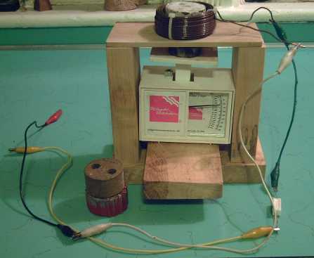
Coil test jig setup
(I finally bought another more precise digital scale towards the end of the month - the new one actually seems to work.)
Looking at the chemistry of Laguna Borate, I see it's choc full of good glass forming things already mixed for the amorphous glassy substrate. Including of course the boron. Frit, essentially finely ground glass, will help out.
The other component is the substances for the nanocrystals. Iron would be traditional, and-or nickel and cobalt, for ferromagnetism. Unlike nickel metal itself for alkaline battery materials, nickel oxide, carbonate and sulfate are readily available at local pottery supplies.
As I thought about it, an "amorphous glassy structure" sounded much more like a pottery glaze than a clay body. Perhaps then the structure should be:
* thin strips of ceramic or porcelain - simply something to apply a glaze onto.
* a glaze in sodium sulfate ("water glass") with minerals containing magnetic elements which are likely to segregate into metal and oxide elements (per web info) - perhaps mainly ilmenite, rutile or an iron oxide, and borate, perhaps with barium carbonate. Copper was also mentioned as selectively forming the metal, giving its oxygen to, um... some other metallic element.
* Perhaps even two (or more) glazes in layers, applying the highest temperature one first, then the lower temperature one, firing which wouldn't get up to the temperature that would de-crystallize the first one.
The glaze(s), rather than the clay, would then be quenched when glowing hot, raku style, in accordance with the techniques and jigs already worked out above.
Barium titanate (BaTiO3 = barium carbonate + rutile - CO2 ?) is one of the materials mentioned in the connection of nanomaterial and strong magnetism, and boron is always in there somewhere, (eg, in NdFeB supermagnets) and is also a "glass forming element". Ilmenite is FeTiO3, the titanium plus iron. Part of the trick is evidently to pick things that will segregate, one ending up as its oxide and the other as the metal with its magnetic properties.
...Okay, the first try didn't work. (Na2SiO3, ilmenite, laguna borate, BaCO3, custer feldspar - cone 6 (1000c) March 29th.) A good question is whether a reducing atmosphere in the kiln might help - after all, we want some metal(s) nanocrystals, not all oxides. (The one time I tried this, I was amazed that a charcoal briquette could sit in the kiln and glow white hot like everything else yet not burn up. Of course, it was selectively using up all the oxygen in the kiln - its very purpose - and when that was gone, it couldn't burn.)
March Details
In trying to design a different torque converter - more like Constantinesco's - I made a ratchet with lever arm and push rod, which I also suggested seemed like a good fit for an improved proof of concept ocean wave powered generator unit. After I made it I realized that that torque converter design was unsuitable for the car drive.
So the assembly is now available to be used as a main linkage component for the wave power design. It would be better to have two of them, but perhaps one would get things moving, and anyway I now have or can easily obtain everything needed to do the second one except one bearing race. (I might just find bearings at a motor repair shop? Aha! "dealextreme.com" has bearings!)
This mechanism would eliminate a good deal of the "slop", the free play in the mechanism that contributed to poor working.
The other contributor to the problems was the cogging of the generator, which was fierce. I had expected the force of the waves to overcome any and all cogging with ease and didn't worry about it in my generator design. It didn't - at least not in the waves available at the boat launches I went to on windy days - and so the other thing is to ditch my generator (still makes a great car motor!) and get one with little or no cogging.
And I knew of one that's readily available... one of those direct drive electric lawn mower motors. Then I just need to re-configure a new version of the power transmission assembly from the floats assembly so the waves can drive it.
I wasn't about to leap right in and start with so much else on my plate, but I thought I'd keep my eyes peeled for the ever scarcer $50 used lawnmower. UsedVictoria.com was bleak - there were more people looking for them than selling them. I remembered the mower A & C Equipment had offered me one a few months ago for $75. Chances seemed slim it might still be there, but I ran down there and asked. Nope. I asked what a new motor would cost, and in the end the guy went into the back and came out with two motors, a 12 and a 9 amp. "Don't know what condition they're in. They're yours." he said and handed them to me! I thanked him and said he'd helped ocean wave power.
To make a long story short, the big one had some burned out coils, but with some fixing and fitting of a new brush the small one ran fine at 12 volts (3.1 amps) or 24 volts (3.7 amps), and generated a few volts when turned. It works! The RPM to get 12 volts is going to be rather high, though. It will be ironic if I have to rewind a 120 volt motor to get more voltage to make 12 volts.
Anyway, I now have all the main components for an improved proof-of-concept wave power machine!
March Details
In searching for sources of nickel, I ran across and read a little treatise by DREO/CSA about making the very successful nickel-cadmium batteries for the Alouettes and a couple of other Canadian satellites, and it seemed they made the electrodes very similarly to my own plan for the alkaline electrodes. They started with a nickel mesh, and they sintered carbonyl nickel powder onto it to make a conductive porous sheet. Then they vacuum impregnated the sheets with nickel nitrate or cadmium nitrate powder. Finally they passed current through the sheets, submerged in potassium hydroxide solution, which converted the nitrate to hydroxide. They also 'coined' the sheets, compacting around the edges and a couple of other places to eliminate any protruding mesh wires (after having trouble with shorts).
My plan is to start with nickel mesh, mix nickel powder or flake and maybe a little cobalt oxide (for conductivity) with nickel hydroxide (which I already have, so forget having to make it from nitrate), plus veegum and CMC gum to hold it all together, and compact these (wetted) powders into a thin electrode "briquette". Similar for the manganese 'negatrode' except I can use stainless steel mesh, a mix of manganese and manganese dioxide powders, and perhaps a different conductive metal powder -- if it's even needed.
One 'refinement', if such it is, is I plan to fold over one long edge of the mesh and embed a ~#15 leed wire in the mesh across the entire edge of the electrode, to connect to the terminal post. (I may flatten the contact portion that wire in the rolling mill first if it seems too thick.)
Since nickel electrodes swell in use, I'm going to back the electrode with the Arches 90 pound watercolor paper, which can compact a bit as the electrode swells. I won't use sheet nickel backing - with the conductive nickel mesh to carry current to the wire and the wire to carry it along, it seems superfluous. Paperback batteries!
Well, I decided to try to order nickel material to make alkaline batteries, or more specifically, to make the 'positrode' for them. I called one place and they seemed to have everything, which I thought would be very convenient. They e-mailed me a quote that took my breath away! For my few little pieces, perhaps 3 pounds, including the tiniest mesh screens that weren't even big enough for one electrode, they wanted 782.54 $US! With shipping and taxes, that would be over $1000 for a few scraps that wouldn't go very far even for experimenting. At another site it seemed nickel was 2.50 $/pound from the mines.
Then I asked a place in Ontario, a wholesaler that imported nickel screen from China, if they had any dealers. I included the absurd quote for $205.50 for a teeny little piece from the American company, and they offered to give me "a much better quote than that!" for my needs, a few square feet. I asked "How about you just send me all you care to send for $75?... and by the way do you know offhand where I might get nickel wire, rod, and powder?" Then I didn't hear from them again in spite of two more e-mails, until I phoned on the 30th. Then, the quoted prices of $40-$50 per square foot took me aback.
Perhaps I'll have to nickel plate other metals - even just for experimental quantities. My nickel brush plating solution doesn't seem to work any more, but a new bottle for $50 is starting to sound very attractive.
About the end of March I suddenly realized that I had a possible solution to part of the battery making and testing problem at hand. I had a dead Ni-Cd battery pack from an old cordless drill someone gave me - 8 cells with only one that charges. It seems that Ni-Cds usually die by shorting through the separator sheet, therefore, the electrodes should still be good if separated.
For the first time in my battery experiments - and for alkaline batteries only - here's a possible way to test each individual component, one at a time.
First, disassemble the battery and unroll the electrodes. Hopefully they will retain their integrity. (This drill is so old they're probably 'solid' sintered electrodes rather than compressed powder types. That will help.)
Separate them. Re-compact them (flatten) if it seems necessary. Remove the separator sheet and put in a new one. Put it in some sort of case, with the electrodes flat. (Ensure minimal exposure to air - CO2 in the air turns the KOH electrolyte into K2CO3 + H2O.) Top up the KOH for the extra moisture the new sheet will absorb, and a bit of water for what's evaporated, and close the case. (Vented case.) Now the battery should charge and discharge pretty much as it did when it was new. If it doesn't, it's the separator sheet or something basic in the setup is wrong, because the electrodes used to work. This can also be used to test the effectiveness of various separator sheets and compare the rate of current flow they provide.
Second, make a manganese electrode and put it in in place of the cadmium one. If that works, great, we're off to the races! (should have our ~2.04 volts open circuit.)
If not, make a zinc electrode and try that. (~1.75 volts O/C) Since nickel-zinc is known to work, if this doesn't work, something is wrong with the way I'm making the electrodes. On the other hand if the zinc works, the electrode construction must be okay. It's possible then that the manganese chemistry doesn't work as expected.
Once (and if) I get that working, I can try making and testing new nickel electrodes. Then I'll have replaced, one piece at a time, the old Ni-Cd cell parts with the new types.
I think I'll still need that new bottle of nickel electroplating solution, if only for making connecting wires that won't dissolve!
What's the energy potential by comparison? Manganese is 1/2 the atomic weight of cadmium, so double the amp-hours per kilogram (this isn't strictly accurate once the OH-'s are factored in, but we'll use it for the equation) and a voltage of 1.56 volts instead of .82. 2 * 1.56 / .82 = 3.80 times the energy density of cadmium. (We don't actually know if the Mn will become MnO or the heavier "hydrated" form, Mn(OH)2 when discharged. Cd -> Cd(OH)2, the heavier form.) Call the energy density at least triple, anyway. Over double that of a good metal hydride. The nickel side won't be much different from other nickel electrodes. Any I make will be a good modern powder type.
I had considered that there appeared to be just two ways to connect the electrodes to the terminals, in particular the positive side, given that solder would corrode away: Bolts made of something that wouldn't corrode (hopefully stainless steel with salt electrolyte - only pure nickel works for alkaline cells), or spot welding. Bolts are tedious and can come loose; spot welding is not amenable to small scale, minimal investment manufacture. (Hah! - even DREO had to go to NASA for help getting the welding right!)
As an example of the power of the corrosive power of the 'positrode', I used a #4 plain coated nut and bolt in the present perchlorate battery. I took it apart weeks later and found half the nut, corroded away and fallen down, and none of the bolt at all. (though perhaps some remainder fell to the bottom once the nut was gone - I didn't check down there.)
But now I've thought of another connection technique: riveting. Stainless steel rivets should work as well as stainless steel nuts and bolts. Perhaps I'll try this next time. Nickel rivets for alkaline cells... if there is such a thing. Or nickel plated.
The battery case plan has been in place for a while, but hadn't actually been made in its planned final form. While shopping on the 30th, I bought some #10 - 24 threaded rod to use for 7-3/4" 'bolts', having earlier formed a rectangular ABS case body from 3" circular plumbing pipe, and having already bought 3/8" thick acrylic plastic for the top and bottom covers.
I cut a couple of covers and drilled the holes, threading the bottom ones so nothing would stick out the bottoms.
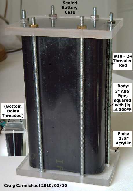
If the acrylic seals well against the softer ABS when the nuts are tightened, it'll be good as is. If not, a rubber gasket (eg from an inner tube), cut to fit, seems to work well. The bottom could be gasketed or glued. The cells inside had better be good - so far it's 600 grams and provides zero watt-hours!
If this case seems a bit cluttered, heavy and labour intensive, it also has its advantages:
First, it's the only form of sealed case I've made so far that's held under pressure, which sealed cells do build up when charging.
Second, if a cell shorts out, it can be opened, the offending electrodes pried apart, and new electrode separator sheets put in. That could extend the lifespan to decades.
I've been reluctant to do alkaline cells, as the perchlorate chemistry promises to be better all round: I expect lower pressure, much higher current density, and higher energy density. But if I can't get that going for now, at least Ni-Mn should be almost a double step up over, eg, Ni-MH, and potentially far more economical than lithium.
There are of course things that could go wrong with this seemingly predictable chemistry, too. I haven't tried it yet. Nickel hydroxide positives are well known, but the manganese 'negatrodes' are an unknown. AFAICT no one ever seems to have tried them, and it might not work out like the properties of manganese I'm aware of seem to indicate. Or, my techniques or my chemicals (not all are of known quality/purity) might conspire to produce unknown problems I personally can't figure out with my limited chemical knowledge and primitive test setups. (...as seems to be happening with the perchlorate.)
Still, they seem quite a good bet, and the idea of using the "known-to-work" dead Ni-Cd cell electrodes for testing will make it much more evident where any troubles originate, an advantage I don't have testing a completely new chemistry type.
March Details