Turquoise
Energy Ltd. News #27
Victoria BC
Copyright 2010 Craig Carmichael - May 4th 2010
http://www.TurquoiseEnergy.com
Highlights/Contents:
April in Brief
(summary)
* Another month of gradual progress in all
directions on each project:
Electric Hubcaptm
Car Drive System Project
* Motor Controller Modification: Ditch the 7uF coil filter capacitors
(works better without - coil spikes are no larger).
* MC33033 obsolescence. New chip?: probably Allegro
A3938.
Mechanical or Magnetic Torque
Converter
Project
* Vibration and poor thrust plague latest design.
* Very promising new design worked out:
- shifting and consequent vibrations are
radial instead of
axial, and should all cancel.
- thrust is repeated 'tugs' at the wheel instead
of 'hits'.
- May be made as either mechanical or
magnetic type. (guess which one would be quietest)
- Still quite simple, no "stator" piece
needed.
Nanocrystalline
Ceramic Motor Coil Cores Project
* Ceramic glaze compositions examined: the
commercial mixes of metallic elements.
* Fired some porcelain strips to apply the glaze to.
* Batch of rough, dark glaze made, fired, annealed,
fired hotter, annealed - no results.
* Rough, dark glaze?: more clear "amorphous glassy
substrate" needed (borosilicate glass), with less of the metals?
* Tried "glaze
mix 3" variant of previous - looks close to the desired overall form.
Ocean Wave
Power Project (no report)
Turquoise
Battery Project
* Salvaged Ni & Cd electrodes from a dry cell
work as a test/reference
battery
* KCl Salt electrolyte works: same chemistry,
different voltages
* My Ni(OH)2 'positrode' (~+1v, with MnO2 for higher
oxygen overvoltage)... it works!
* Mn 'negatrode' (~-1.3v): bubbles (hydrogen?)
* Ni 'negatrode' (~-.4v): Surprise! it bubbles, even
with such a low voltage.
(hydrogen?)
* Mixed Ni/Mn: less bubbles than either alone! Could
have
high voltage, high effective energy density.
* To raise hydrogen overvoltage: transition metals,
borohydride, and a secret weapon: egg white.
The Lead-Acid/Sodium Sulfate Battery
Longevity/Renewal
Project
* Sodium Sulfate For
Sale
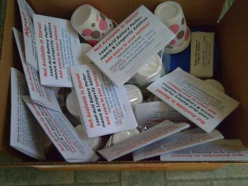
* Convenient packages with instructions and 6
paper cups.
* Key to renewing old batteries: Dump out the crud?
Newsletters Index/Highlights:
http://www.TurquoiseEnergy.com/TENewslettersIndex.html
Construction Manuals for making your own:
* Electric Hubcap Motor
(latest rev. 2010/02/xx)
* Turquoise Motor Controller (latest rev.
2009/12/30)
* 36 Volt Electric Fan-Heater
are at http://www.TurquoiseEnergy.com/
April
in Brief
A pile of battery electrochemical experiments running
through much of the month showed that
(a) my nickel-manganese positive electrode works, (b) a similar mixture
of
nickel and manganese can possibly make a great negative
electrode if a
couple of tricks are used - but It's not there yet, and (c)
that it seems feasible to switch from potassium hydroxide alkali
electrolyte to
potassium chloride salt. These findings mean that
it may be possible to make a nickel-manganese /
manganese-nickel /
salt battery with all the most desirable characteristics: 2 volt cells,
highest energy density, high power density, economical, green, safe,
'indefinite' cycle life, maintenance free. It would be a distinct
advance on the
state of the art in a battery with economical ingredients.
The potential seems to be there, however, even if
I do
get a good negative electrode working, a lot of "tweaking" and testing
will still need to be done before there are
good, working batteries.
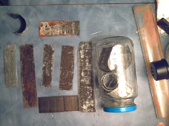
Some battery test electrodes, mine and some commercial ones taken
from dead Ni-Cd dry
cells.
Tests of the mechanical torque converter looked quite
unpromising. I considered trying out some other more complex design of
several
I recently located on the web,
but they all needed a number of precision parts that weren't going to
be found in stores. A couple were amazingly complex. Then I came up
with a more promising idea, not so
different from a couple of my others, but with a valuable addition -
centrifugal swinging arms with shaped ends that would allow the motor
rotor, if it was turning fast
enough, to drag the wheel for a short distance before letting go,
with a torque advantage. I decided to try it out and did some paper
cut-out arms to check the fits. Then on May first, I drew up a magnetic
version that would probably work just about the same way, and of course
silently and with the least heat and wear.
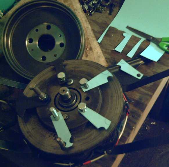
Visualizing the concept: multiple arms "semi-hooking" themselves
onto
pins set around the rim of a drum on the car wheel, tugging the wheel
as
they pass. (drum behind) Magneticly "grabbing" and tugging might work
similarly - and silently.
Attempting to spread the word about sodium sulfate and
the tripling or better of lead-acid battery life, I bought a fair
quantity of it in
March, and in April I packaged some up in single battery doses with
instructions and little paper cups to pour it into each cell with.
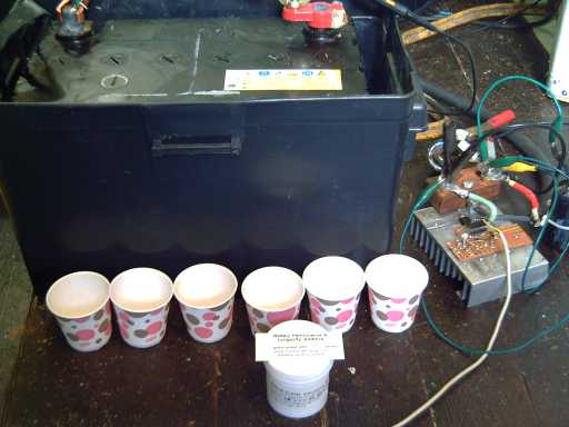
The contents of a "battery longevity kit" package in front of a
battery. To the right is the new interface to allow a computer to turn
a battery load or charger on and off, made on an aluminum heat sink.
With triple or better cycle life and being more forgiving of rougher
use, lead-acid batteries are in fact a pretty decent type to use for
short range
electric transport. No one in industry seems to want to hear that, from
big oil to battery retailers - it would only be of interest to all
those drivers waiting for economical plug-in hybrid cars.
The nanocrystalline cores project crawled slowly along as
well. The new concept of obtaining that "amorphous glassy substrate"
with the suspended "FINEMET" composition nanocrystals moved from being
pottery to the glassy pottery glaze on a thin strip of
porcelain, a glaze being much more the right sort of composition. I'm
now trying to form and refine a fairly clear borosilicate glass glaze,
with the
active ingredients suspended in it.
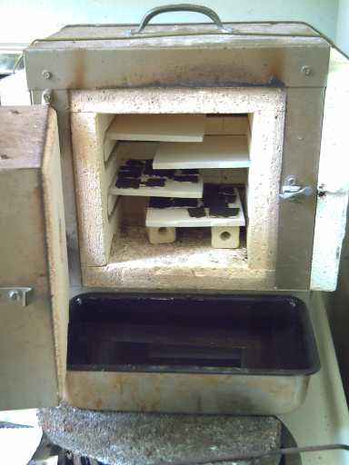
The front loading mini-kiln has been indispensable. Last melt-quench
I used the two little tile "shelves" with the glazed strips on them.
The moment the
kiln was opened, they were yanked out and into the pan of water with
tongs, to quench (rapidly cool) the white-hot glazed porcelain "chips".
(I actually used a big cake pan, to make aiming simple.)
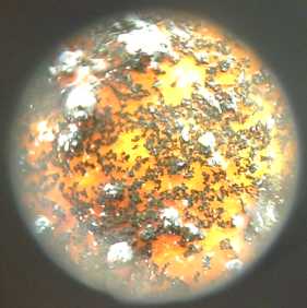
Apparently the desired form, provided by mix 3: an "amorphous glassy
substrate" with the
magnetic substances crystals suspended in it. However at just 10x
magnification, it's the unseen particles
making the clear glass yellow that may hopefully be "nano" size. (Where
did I put my SEM?) The big ones probably result from my grainy FeO.
Tune in next month to see how and if it worked.
The Electric HubcapTM
Vehicle Drive System
Motor controller changes
Somehow, I had got the idea that I should use some small
capacitors as filters in the motor leads, that they would damp the
spikes coming back from the coils. I put in 7uF motor "run" capacitors,
which took up considerable space in the motor controller box. In some
discussion on a motor controller design chat list (yes one exists!) I
mentioned this and the feedback was all negative. So I took them out.
Sure enough, it runs better without them and the voltage
spikes from the coils, as far as I can tell on the oscilloscope, are no
larger! Well, that clears up some mystery of why my controller didn't
like higher PWM frequencies... and clears a fair bit of space in the
chassis.
While I had the oscilloscope on, I noted that when the
motor is up to speed (~1600 RPM) and the drive is suddenly shut off,
the waveform from the coasting motor immediately drops by only about 6
volts: the back EMF generated by the motor at full RPM is 30 volts out
of 36 - the coils are effectively only getting 6 volts, and the rising
generated voltage sets the maximum RPM. To do regenerative braking, one
must amplify this generated voltage to a level above the battery
voltage.
I have also noted that the MC33033 motor controller chip I
used is (to be) discontinued. Another chip, the Allegro A3938 looks
like a better chip, and a very good fit for a 36 volt motor. It
eliminates the three half-bridge drivers by incorporating them
internally. But it has as many pins as all four chips on my present
design, and it has no PWM generator, so I have to add a small chip for
that.
So it looks like I'll need to do up a new circuit and
circuit board for this sometime. Amazing how the job list just keeps
growing after you think something is "good enough" and you're "done"!
But
one advantage of my layout with the hard-wired power components is that
the driving logic board is just a small piece. Indeed, one could
substitute any sort of driver logic board for different motor types,
microprocessor control, etc.
If I made the connections via a connector plug or header
strip instead of solder-on wire pads, changing or upgrading the
controller logic could be a simple plug-in job. (On the other hand,
solder makes the most reliable connection.)
Mechanical Torque
Converter Project:
Torque Leverage Without Gears
I got excited by at last
making good progress with battery
designs, so the torque converter project continued to proceed in very
low gear. But the work done in recent months, however gradually,
was finally finished up. I
switched to the idea of spring return, conceived at the end of March,
when I realized I could simply slip four smaller springs onto the link
pins and unbolt the upper ramps, making the change trivial. And Capital
Iron even had suitable springs ready made. I still had a feeling it
wasn't
going to work very well (which did much to limit my enthusiasm for
working on it).
I tried it on the car on the 13th. There was again a lot
of vibration. The car did grudgingly
back up - down a slight slope - if I put my foot against the motor to
hold
it against the wheel - bumping back a tiny bit at a time with each
torque hit. (I even managed to get a bit of video of this, but I
decline to post it as things have moved on.)
The springs weren't solving all the problems. But in this
test, seeing the motor bouncing outwards and
yet the car starting to move, I realized that if I turned
the axis of the strike 90º, the sideways vibrating force
would generate pulses
outwards instead of sideways. If four pins strike four ramps each
90º spaced around the rim, all the forces causing vibration should
cancel each other out, leaving only the rotary force. This brought me
back to the clock escapement type of mechanisms.
However, when I had disassembled the key pieces and I
started to consider actually implementing this sort of design, it
started to look more complex. Finally I put it all together again and
tried it out again. This time I noticed that although the car wasn't
moving, the metal part of the car wheel seemed to be vibrating back and
forth - it
would seem perhaps the rubber tire was absorbing the torque hits,
bouncing back and forth without the car starting to move. When I took
the motor off, I also found that all four link pins had come loose
(tightly though I'd done them up) - more play in the mechanism! Like
the wave power design, this mechanism only works if the small back and
forth
motions aren't taken up by slack in the system.
I started to consider how to get stronger individual
torque hits as well as tighten things up. The strength of the hits
depended on (a) the mass of the inertia piece (b) the ramp angles and
(c) the speed. The speed seemed high enough. Changing the ramp angles
had some effect, but evidently the mass hitting the ramps had to go up
considerably. How could I increase the mass of the torque plate?
Probably not by replacing the plate with smaller
"escapement" pieces! That pretty much scotched the idea of doing it
that way.
Well... How about if the entire motor was the inertia
plate? 45 pound hits instead of 5. That's about what was happening when
I pressed the motor in with my foot and it finally moved the car
(however little). And, once thought of, it seems more like the sort of
weight for a hammer that might move a car!
But it struck me that if the rubber tire let the
rim move forward a jog and then bounced it right back again, perhaps
the whole idea of using "torque hits" wasn't going to work, at least
not very well here, because of play in the system that couldn't be
eliminated. Even the whole motor is very little mass to strike with
compared to the mass of the car - like driving a spike with a tack
hammer. For the lightweight motor, we evidently need another approach.
Unfortunately it seemed likely to be more complex.
An internet search using Altavista brought up more designs
than when I tried it quite a while back with Google. Where
were these back then? I studied some of them to see if there were
any
that could be metamorphosed into the sort of physical shape required
for
the Electric Hubcap. But they looked complicated and needed precision
made parts that
certainly wouldn't be "off the shelf".
What about more powerful hits? If the diameter of the drum was larger,
they'd have more leverage. What if, instead of a drum, say about five
"things" were sticking out from the wheel rim for five weighted
flailing "arms" from the motor rotor to hit, all at once? That could
have considerable striking force, and
the vibrations would all cancel. The motor would have the fewest parts:
indeed, any old axle system and construction of the motor would work.
No more need to turn down trailer hubs on a lathe! When the motor and
wheel were spinning fast enough, the weight of the arms would "lock"
them into 1 to 1 drive. The motor would be flexibly connected to the
wheel.
All the previous principles remain in play. The
force of each impact will be regulated by the angles, the weight
of the inertia pieces, and the speed. The leverage provided by the
force would be greatest out at the wheel rim. And it would be simple -
very, very simple.
But then I considered that there could be other torque
developed by this layout
besides an initial hit: By adjusting the length and shape of the outer
ends of the arms, they can be made to twist to an appropriate angle
before letting go, to drag the pin around for a short distance with a
"gear ratio", as the motor turns to a given relative angle, to pull the
wheel around and give advantageous torque leverage. In fact, let's
forget the 'hit': strike at a shallow angle, and let the 'inertia
hook' drag the wheel around a bit as each arm goes by each pin. I think
this
version of the "torque hits" mechanism sounds like the most promising
one yet!
Looking it over, it appears the rim of the wheel could be
accessed best by a plate bolted to the wheel. But that diameter isn't
so much greater than the 10" drum, so using the drum - and having all
those flailing arms safely enclosed - might still be the best idea.
The arms of black styrofoam (shape 1) and green cardboard (shape 2).
One arm is seen in concept of "dragging" past a pin, which would be
attached to the drum (behind) on the wheel. Probably these arms will
have to be about as heavy as I can make them - goodly chunks of 1/2" or
3/4" steel, with semi-hook shapes that _almost_ won't let go of the pin
as the motor spins it by.
The length and shape of the arms being
evidently important if not
critical to this design, I did some concept visualizing with a
styrofoam package and then green paper, which are both easier to cut
than slabs of steel. The idea is that the ends of the arms almost hook
onto the
pins on the wheel, but not quite. As the motor turns they'll pull the
wheel for a short distance as they're slipping off each pin. If the
motor is
turning fast enough and the torque required isn't great enough to slow
it down, the arms will stayed "hooked on" by centrifugal force for a 1
to 1 direct drive. In this layout, the
arm
pivots are at 2" while the wheel pins are at about 4". The 'gear ratio'
achieved will depend on the
speeds of both motor and wheel, the weight and shape of the arms, and
on the torque being transmitted.
Then on the first of May, as I sat listening to someone speak, I
started doodling on a piece of paper and drew up a very similar design
with magnets replacing the pins in the rim of the drum. Each steel arm
will jump forward by attraction as it approaches a magnet, then it'll
swing backwards more and more, trying to stay at the magnet. As it
passes, the motor will be trying to pull the arm away from the magnet,
creating a similar tugging force on the outer drum to turn the wheel.
I've just realized that the best test will be if you can
stomp on the gas pedal when stopped, and the wheel spins out. If the
torque converter can achieve that, it's really working!
What is a mechanical or magnetic torque
converter? What does it look
like? What are its main features? How does it work? For me the entire
idea
began completely undefined and as clear as mud, as a need for a
specific function that isn't performed well by existing designs (gears)
that most of us are aware of. How many wildly
different versions have I gone through so far, including ideas,
designs, construction
and tests of various magnetic and mechanical converters? And how many
wildly different (and convoluted) designs are out there on the web?
That's what
inventing something new is all about.
Now if after a year of puzzling over the problem and
trying
various things out I create a simple working model of torque converter,
in its simplicity
anyone will easily grasp how it
works,
copy it, and improve upon it. If it gets a good start, it'll spread
until it's the automotive standard and heavy, crappy transmissions have
gone the way of the dinosaurs. The suddenly "obvious" principles on
which a 'simple' new invention works, and which
no one sees any reason to pay some weird guy for afterwards just
because he
made the first one, are often
hard won. Until now, none of my designs have worked very well, and
nobody else has come up with anything that's been adopted, so everyone
continues to expend their efforts and money on, and contend with, those
dinosaur transmissions.
If I had found a design on the web that I could use or
modify, I would of course have simply appropriated it myself for the
Electric Hubcap system.
And all this is why
sensible people don't get involved with inventing -- it'll remain a
wretched, impoverished career as long as society offers only lip
service encouragement and pie-in-the-sky promises of "you'll be rich!"
but no real, working mechanisms for paying inventors either for time
spent, for working inventions once
eventually completed, or even after their profitable adoption by
society.
Nanocrystalline
Ceramic Motor Coil Cores Project
The whole field of nanotechnology is pretty new, and
evidently the magnetic ceramics area isn't very well explored. I
thought there were probably people around somewhere who knew how to do
this if I could find and ask them, and doubtless I'll find many more
pointers on the web, but perhaps I may be breaking some new
ground.
The difficulty of applying such materials to traditional
motor designs is perhaps illustrated by omission in one paper (Soft
Magnetic Nanocrystalline Alloys, Journal of Optoelectronics and
Advanced Materials Vol. 5 No. 1, March 2003) that suggests applications
such as "choke coils, transformer cores and power transformers".
Implicit in leaving out motors is the idea that they would be too
difficult to fit, large sheets of material being required to die-cut
their cores rather than the simple "tape strips" being produced by
current techniques. The Electric Hubcap's
individual component, bolt-on "fat
hockey puck" coils can use whatever's available.
Three nanomagnetic alloy formulations are the first one
determined in 1988, Finemet,
along with Nanoperm and Hitperm.
FINEMET: Fe 73.5(%), Si 13.5, B 9, "M" 3, Cu 1. Metal "M" can be Nb,
Zr, V, Mo...
NANOPERM is similar but without the silicon, eg: Fe 84%, B 8, Zr 3.5,
Nb 3.5, Cu 1.
HITPERM adds a lot of cobalt to NANOPERM: Fe 44%, Co 44, Zr 7, B 4, Cu
1.
Traditional high permeability transformer core alloys
saturate at 1.6
to 2.2 Teslas. A table shows HITPERM with the highest saturation
magnetism (1.6 to 2.1 Teslas) and FINEMET with the least (1.0 to 1.2
Teslas). Amorphous FINEMET cores (rather than nanocrystalline) saturate
down at 0.125 Teslas, so getting the nanostructure correct is
important. But the text says FINEMET has the most promising
combination of permeability (10^5 at 1 kHz) and saturation
at room temperature. At higher temperatures, it craps out, but it
doesn't say what temperatures. I'm going to assume the motors don't
reach those temperatures.
Actual work during April started with annealing glazed
strips
made in March and finding no positive results, then preparation of a
new
batch of porcelain strips to paint the "finemet" glaze materials onto.
This time, care was taken to keep them pressed flat while drying, the
first batch having had many annoyingly warped and curved shapes. Still,
the pieces didn't end up as flat as might be hoped. In principle, the
clay strips should be as thin as possible - they're only there to hold
the glaze until it dries and the firing is done. But they break easily.
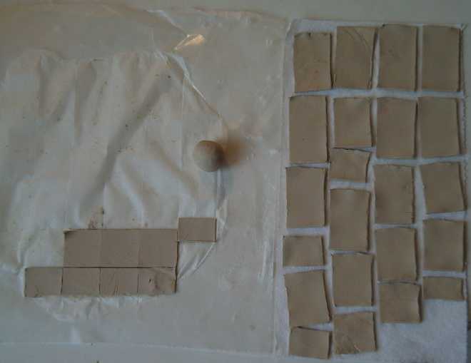
Porcelain clay cookie cutting. I need to get the thickness more
uniform and keep them pressed flat (while somehow allowing the moisture
to escape) as the clay dries.
Next step was to estimate what combination of minerals
would
give something like a "FINEMET" composition. For "Glaze Mix 2" I used
titanium for metal "M" -- it's next to Zr, Nb and V on the periodic
table, has some similar magnetic characteristics, and
it's cheap. And some zirconium, also pretty cheap. So I mixed: FeO
60% (60 grams), laguna borate (for the boron) 20%, Ilmenite (Ti:Fe:O)
10%, zircon
(Zr:Si:O) 5%, and copper sulfate crystals 5% (total 100 grams/100%),
all watered down to a
pottery glaze in lots of sodium silicate "water glass" (~60 grams?).
It made a dark brown, somewhat greyish, chocolate syrup.
As suspected, the copper sulfate crystals remained as big lumps.
Hopefully enough would disperse when melted during the firing.
I tried firing for 75 minutes (then quenched, each
firing), annealed for 15, refired for 85 minutes, annealed again, then
fired for 95 minutes, then annealed again. Each time, the magnetic
field was no stronger than for air. The glaze was slightly attracted to
supermagnets.
I am of course handicapped by not
having access to the sorts of test equipment for techniques usually
used in this field: Mossbauer spectroscopy, SEM, TEM and a couple of
even more unfamiliar names... and by not knowing how to use them if I
had them. It would be nice to link up with someone who could give me
some
sort of idea of what general stuctures I'm creating at the nano
level. About the only things I know of that I can check are the field
strength by putting it in the center of a coil, whether it's
attracted to a magnet or not (of "incidental" significance), and the
visual appearance at x100 micro and larger scales.
One thing that bothered me was that the glaze was lumpy
and dark
instead of more smooth and clear. The metallic ingredients are supposed
to be dispersed in an amorphous glassy structure. I fear this glaze had
far too little glass in it.
A typical borosilicate ('pyrex') glass composition is
about 70% silica, 10% boron
oxide, 8% sodium oxide, 8% potassium oxide, and 1% calcium
oxide (lime) [per Wikipedia]. We get silica and sodium from the
sodium silicate 'water glass', the boron from the borate (...maybe
borax?). We seem to need more silicon in proportion to sodium (and all
the FINEMET stuff), and more boron. We've missed the
potassium and the calcium
entirely in "glaze mix 2", though potassium isn't so different from
sodium, which we seem to have too much of.
There'd be no need to find calcium oxide - calcium carbonate will break
down
into that as it heats up (CaCO3 => CaO + CO2 above around
800ºc). I might also try barium
carbonate in addition or instead. It would be pretty similar (but I
must look up the breakdown temperature -- hmm, doesn't look right on
Wikipedia...), and we're
already adding the titanium - to form some barium titanate, a substance
of value as mentioned in a couple of places for magnetic nanomaterials.
On the morning of May 3rd after a weekend away, I added 3g
of barium carbonate, 8g of potassium hydroxide, and 20g of Laguna
borate to the 150g or so of glaze mix 2, to make "glaze mix 3". I
noticed the copper sulfate crystals had turned into blueish blobs.
Effectively dissolved, there's about 4x too much copper - oh well.
Also, the whole thing had hardened in it's margarine container in a
week even with the lid on, and I had to add water and sodium sulfate,
break it into lumps, break up the lumps, and mix it all up again. On
mixing with the new materials, it lost much of its ilmenite brown
colour and became more greyish. But when painted on and dried, the
brown reappeared and stayed after firing.
If a mix and process can create working nanomagnetic
glaze, it remains to be seen how to use it. If it's just a glaze on
clay strips, there'll be much of the core filled with inert clay. If
the glaze is attracted to magnets, however little, the glazed strips
can be ground to powder and a magnet can fish out the magnetic material
while leaving the clay behind. Then the nanocrystalline powder can be
cast in epoxy or other material. Polyester resin, plastic or even wax
might work, though high temperature epoxy would have the best specs.
Motor varnish is possible, but it would probably do too much bubbling
and mess things up. (My brother, a biochemist, thinks sodium silicate
plus calcium (carbonate?) might harden into a permanent silicate, and
I'll probably experiment with this -- if it doesn't need a high
temperature to make it work.)
Ocean Wave Power Project
(No report.)
Turquoise Battery Project
The
Ni-Ni Cell and Ni-Mn Cell: April Experiments
Battery experiments were almost contiuous throughout
April. Per the plan determined about the end of March, I took
apart an old dead (shorted) Ni-Cd cell and used the electrodes as a new
battery with a new separator sheet. Though the connections weren't very
good and I couldn't get a seal ('0 PSI'), it held a charge. A working
battery meant further experiments could start with one untried element
at a time, a luxury I didn't have when trying to test the all-new
perchlorate chemie.
A bunch of experiments of early April:
Top: new curled up 1/2 electrode from Ni-Cd cell, a used one with rust
and (?)zircon.
Lower row: Zinc electrode (it worked, but zinc gradually migrates (so
does cadmium), and it seems Ni-Zn at best are only good for a couple of
hundred recharges), um.. one with brownish permanganate, 3 with
manganese, one having remains of a layer of zircon painted onto it (all
5 made compacted onto fine stainless steel conductive mesh.), jar with
commercial electrodes (mostly cadmium), the flattened acryllic plastic
test battery tube with pressure gauge.
Bottom (horizontal): Flattened nickel electrode from Ni-Cd cell. They
buckle in places when flattened. These ones are sintered or paste
compacted around perforated steel foil. The positrode foils are
doubtless nickel plated.
Main Features and Findings
Here are the main features and findings in brief. I wrote
great gobs of
great gory
details which I finally decided were best saved as a file of scattered
notes and left out of this newsletter.
* The salvaged Ni-Cd battery electrodes worked in alkali, providing a
starting point
for experiments.
* Switching the electrolyte from alkali (KOH) to salt (KCl) also
worked.
There were side effects (rust), that would be eliminated by choosing
other
materials. I now see virtually no chance I'll want to use alkaline
electrolyte. KCl is evidently a
faster electrolyte (allowing higher current flow) as well as being much
safer
to work with, and it doesn't degrade with atmospheric contact. Perhaps
surprisingly, many reactions remain the same
(oxides and hydroxides are produced, not chlorides). But the voltages
shift. Many positives like nickel and manganese increase in potential,
while negatives decrease. But the cells mostly seem to be a little
higher voltage overall. (Eg, Ni-Cd looks like it should be around 1.65
open circuit volts instead of 1.35.) Compatible electrode materials
must be chosen.
(Eg, the iron in
Ni-Fe and Ni-Cd - actually an Fe:Cd mixture - doesn't like salt,
whereas alkali is a rust inhibitor.)
If the positive voltage had been above +1.36 volts,
chlorine gas would be generated, but it's not. Electrode substances and
structural materials that will probably work well in salt water
include:
monel,
nickel-silver, stainless steel, maybe copper. That seemingly
"unobtainium", pure nickel metal and powder, needed in alkali
'positrodes', isn't needed in salt.
* The voltage of the nickel [oxy]hydroxide
positive shifts from +0.5v to about +1v, which is a good energy density
improvement if a
matching good voltage negative can be found. (The reaction voltages for
neutral solutions aren't shown on the charts, hence my estimates of
"about" midway between acid and alkali voltages.)
With manganese added, increased oxygen overvoltage
should allow the nickel to go from valence of about 2.25 (discharged)
to valence 3.8 instead of just to 3.0 (charged), yielding the high
energies of recent Ni-MH batteries such as the 2.6 AH "AA" cell, which
has 100 WH/Kg. (Another possibility is that it won't even need the Mn
to effect this desirable change. That could happen if the oxygen
overvoltage goes up faster with acidity than the NiOOH reaction
voltage, which is very possible -- it's evidently over +1.69 volts in
sulfuric acid, allowing lead-acid batteries to work.)
* A nickel-manganese positive worked pretty well using cadmium
electrodes from the Ni-Cd's for negatives, but lost its charge
overnight. This is the first powder/paste electrode I've made that has
been shown to work. Doubtless it can be improved, or it may improve by
itself. The loss of charge
may be related to the rusting of the cadmium electrodes, which were
made to work in alkali. Once these materials are changed the problem
may disappear. If not, it will be addressed then. Or, the electrode may
simply need time to "form" - it may hold charge for a longer period
each time until it's fine.
* The manganese negative turned out to bubble hydrogen audibly - the
hydrogen overvoltage is a bit too low. Likewise, a nickel negative,
even though under 1/2 a volt or so, also bubbled hydrogen audibly. This
was a surprise and
a disappointment -- I thought Ni-Ni 1.1 volt cells were a "sure-fire"
fallback plan! It turns out
nickel is a great thing to use if you want to generate hydrogen because
of its especially low hydrogen overvoltage. However, a
combined electrode of nickel and manganese (made as a "+" and tested as
a "-" on a whim!) didn't bubble much as far as I could hear. But it
also didn't hold charge. Transition metal additives such as tin,
bismuth, gallium, indium or antimony (or oxides thereof) can be used to
increase the hydrogen overvoltage. Experiments continued along these
lines.
* Albumin, the stuff of egg whites, turns out to be a major increaser
of hydrogen overvoltage. Even minute amounts might raise it by up to
1/2 a volt. This discovery (made in 1964 but not mentioned in any
battery literature I've found) makes
the experiments more promising. It may prove to be a key ingredient.
* I am currently charging an electrode with 60% Ni(OH)2,
40% Mn, 1% Sb4O6, and a smear of egg white. And I added a
bit of Sodium Borate (borax) to the electrolyte. It's taking its own
sweet time 'forming' - weeks - but it's gradually holding more voltage
longer and may eventually (sometime next month) prove to be the working
negatrode for that elusive 2 volt cell.
Lead-Acid/Sodium
Sulfate Battery
Renewal Project
April Details
In looking for anything authoritative on the life
expectancy of lead-acid batteries treated with sodium sulfate (or
alum), I found an interesting story: In about 1998 someone with Hot-Rod
Magazine designed an 'ultimate' lead-acid battery.
[http://www.theautochannel.com/news/press/date/19981215/press001556.html]
It had spiral plates (Planté's original 1860
format), calcium and silver in the plate grid for durability and
conductivity, "paste expander" in the negative plates for greater
conductivity... and
sodium sulfate. According to the article, the
sodium sulfate was supposed to "help them accept a charge more quickly
and hold it longer". It was expected the batteries should last "22%
longer".
The magazine approached Interstate batteries, who agreed
to manufacture them. Seems they dropped the "Hot-Rod" name called it
the "Optima" line of batteries. (...and we thought a battery company
came up with
these (known techniques) innovations on their own? Hah!)
Canadian Electric Vehicles got some of the early
Optima prototypes, and according to the owner, the difference was
amazing: they lasted five years in an
electric car instead of "the usual 1 to 1-1/2 years". Then they
couldn't get more for some years - they weren't in production. Finally
Interstate supplied more, but the new ones only lasted 1-1/2
years.
I suspect what happened was this: Interstate management
made the decision to make the "Optima" batteries on their own in
conjunction with Rod-Rod magazine, and put them into production. When
the corporate shareholders - doubtless the same clique who control big
oil and the automakers, who think life is just a big game of Monopoly
where they get to make the rules - found out how long the batteries
were
actually lasting, they were as horrified as the customers were
overjoyed, and had production halted.
Then Interstate continued making them, either without the sodium
sulfate, or,
better yet, with a tiny quantity that won't
do much good. That way they can now say, "Yes, they contain sodium
sulfate." and leave people to draw the "obvious" conclusion that sodium
sulfate doesn't make a big difference.
So I'm pleased to have worked out by experimentation a
fairly optimum amount to put in and to spread the word about it. As I
feared, I'm hearing more and more in recent months about 'sealed'
batteries with glued-on lids that you can't easily get into, seemingly
a diabolical countermeasure to finding that people are discovering
how to access this piece of "suppressed technology" for themselves.
Sodium
Sulfate for Battery Renewal (Click for Prices, Info.)
Last month I obtained a 30Kg bag/keg of anhydrous sodium
sulfate to
treat/renew batteries.
This month I packaged them in small quantities to sell
from $7
(average car battery) up, for anyone who would like to treat
their own battery(s) to increase their life span somewhere from
probably double to five times. I spent considerable time writing up
instructions and making package labels.
I found a source for convenient little plastic jars for
the salt, paper dixie cups and (eventually) a good size of plastic
bags. The six dixie cups help to divide the salt into six equal
portions and make it easy to pour it into the battery holes. And, when
pouring the salt in the six cells with the six cups, one won't easily
lose track of which ones are already done and which remain.
Except for direct selling, I don't know who will want to
sell it. Places that sell batteries haven't latched onto it, though one
I gave samples to is going to test it.
It's in the Dump: Key to rejuvinating old batteries?
I was having a hard time understanding why the people
pouring out the acid and putting in alum claim good results renewing
batteries while I, adding in a theoretically better salt, was having a
bad time with shorted out cells and getting generally poor results.
I finally put together part of the automated battery
cycling system: an interface to turn the load on or off - or connect or
disconnect a charger. (That leaves out the other test component, a
connection to measure and record the voltage - for the moment.) The
immediate
intent of this piece was to pulse the charger on and off to attempt to
clear shorts in the cells, which was unsuccessful (as was pulse
charging from a commercial charger with pulse charge) - for the moment
- on the batteries I tried.
The interface was connected to the control computer I created in
1985-86 for the Victoria School District, which I also wrote the
"Control BASIC" language for. The computer program was:
NAME OUT6=BattOn : "Out6 Bit0 (I/O 6 pin3)
NAME VAR6=BattTimer
70 BattTimer=BattTimer+1%5
71 BattOn=(BattTimer=0)
This program runs about 8 times a second. BattTimer counts up to 4 then
resets to 0 on the next count ("%" being the symbol for "modulo", the
remainder of a division); BattOn is only on when that's 0, ie, one pass
out of 5, a brief pulse a little less than once every half second.
Then on the 30th I dropped off some samples of sodium
sulfate
product at Canadian Electric Vehicles and in that process got the
scoop: It seems that
as the plates gradually corrode, they give off dust. (lead and-or lead
sulfate
and-or lead oxides) The powder accumulates on the bottom until it's
touching
the bottoms of the plates, and at some point, it shorts one of the
cells. A battery with more bottom depth under the plates will last
longer before shorting.
This explanation was in accord with the crap I had dumped
out of batteries early in my experimenting.
The
renewal cycling might add a one-time emission of more corrosion dust
that would
have soon come off anyway. Or there might be a one-time emission of
powder from the plates where the salt is concentrated before it
dissolves. (This seems likely, now that I think about it.) Presto! In
older batteries, it might well be
enough to often cause a short. Of course, once the battery is up and
running properly, most of this gradual corrosion and accumulation is
arrested by the additive, and any battery should last much longer.
So the difference between the successful technique and
mine would be that they dump out the battery, and often specifically
clean it out,
whereas I've just been adding the salt and leaving the crap in the
bottom. (...and not even making much effort to mix the salt in and
disperse it.) In May I plan to test this
idea out by cleaning out some batteries with shorted cells and trying
again. (Dumping acid
and crap out of batteries: Ugh!)
http://www.turquoiseenergy.com
Victoria BC