Turquoise
Energy Ltd. News #28
Victoria BC
Copyright 2010 Craig Carmichael - June 1st 2010
http://www.TurquoiseEnergy.com
Contents/Highlights:
May in Brief
(summary)
Editorial: The Disgrace of the Patent
System: the
Need to rethink it
Electric Hubcaptm
Car Drive System Project
* 2 magnets fly off spinning rotor - indicates problems with nickel
plated supermagnets
- I suggest using epoxy coated magnets
instead.
- and screws as well as glue.
* Phase quits (on motor controller?)... needs
investigation... controller looks fine
Mechanical or Magnetic Torque
Converter
Project
* Promising new design with radial forces instead of
axial should eliminate vibration.
* First test: Back and forth rotary torque replaces
axial
vibration; force seems too light.
* Thought up a new positive method to ensure all torque
goes only one way.
* bigger drum, closer magnet gaps, should tug car
wheel harder each time... hopefully enough.
Nanocrystalline
Ceramic Motor Coil Cores Project
* The Ultimate Potential?: "supermagnet" strength
motor coils
for motors with incredible torque?
* Several glaze mixes later, apparently the proper
nanocrystalline glaze structure - but no magnetic results.
* Great glaze structure inspires (gulp) yet another
new energy project with seemingly fabulous potential - see next.
Nanocrystalline Solar Cell
Project
* The nanocrystalline ceramic glaze mix could make a
great
rear electrode for dye sensitized solar cells (DSSCs), with reflection
and repolarization of the light potentially
as much as doubling their solar energy to electricity conversion
efficiency,
eg, from 10% to 15 or 20%.
* DSSC structure with porcelain/glaze backing
* Materials experiments
* The search for a non-prescription solar cell electrolyte
Ocean Wave
Power Project
* Danish wave power project moving ahead: 1/5 scale production
prototype - http://www.dexawave.com/
* His vessel & float design now virtually identical
to mine
* My 2007 design drawings
* Has BC lost out?
Turquoise
Battery Project (no report - had no time to look at it.)
The Lead-Acid/Sodium Sulfate Battery
Longevity/Renewal
Project
* Sodium Sulfate
'battery treatment kits' For
Sale
* Convenient packages with instructions and 6
paper cups.
* Key to renewing old batteries: Dump out the crud,
replace the acid with water and Na2SO4.
* Low acid concentration - SG 1.1 or less the norm for renewed
batteries?
* "Sealed" batteries with glued-on lids: just drill
6 holes in the "solid" side, use 6 rubber stoppers.
* (Fairly) comprehensive info is now on the web at:
http://www.TurquoiseEnergy.com/Na2SO4.html
Newsletters Index/Highlights:
http://www.TurquoiseEnergy.com/TENewslettersIndex.html
Construction Manuals for making your own:
* Electric Hubcap Motor
(latest rev. 2010/02/xx)
- the only 5+ HP motor that can easily be made at home?
* Turquoise Motor Controller (latest rev.
2010/05/31)
- for the Electric Hubcap. (Probably there are commercial
controllers that would work, too.)
* 36 Volt Electric
Fan-Heater
- if you're running your car on electricity, you'll want a
way to defog the windshield and keep warm.
* Lead-acid battery longevity treatment - "worn
out" battery renewal procedure.
all at: http://www.TurquoiseEnergy.com/
May
in Brief
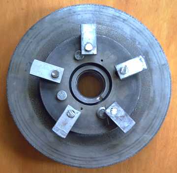
Torque converter side of motor rotor, with 5 pivoting arms.
The arms match 5 supermagnets on the inside of the drum driving the
car wheel.
I got the torque converter
together and tested it briefly
on the car, but a motor or controller problem ended the test. The nasty
axial vibration of the previous prototypes was gone, replaced by
balanced, gyrating rotational forces. The motor seemed to have more
than enough torque to overcome the strong magnetic cogging forces of
the torque
converter and start spinning.
As first impressions (that's as far as I got), it appeared
the
wheel might be
trying to move both directions alternately instead of just one, which
problem I think I have now a good solution for. It also didn't seem to
be
getting
pushed strongly enough. I got a larger drum to increase the radius of
action - the original aluminum frying pan from early in the project -
and will next make longer
arms to match, and will size them with a smaller gap to the magnets to
increase the magnetic
coupling.
I "burned out" for the moment on designing batteries, so I
turned to
the
nanocrystalline ceramic coil cores. By mid month, I had what appeared -
as far as I was able to tell - to be the desired essential form:
nanocrystals of FINEMET elements, embedded in a clear amorphous
glassy
substrate, of borosilicate
glass. But there was no magnetic effect.
Then I found dye sensitized solar cells, ...even
directions
for making them as lab exercises. These use a layer of sintered
nanocrystalline titanium dioxide powder, impregnated
with an organic dye. Transparent and conductive tin oxide coating on
glass... or on the glaze... makes the electrodes. It
all started to look doable (except for the iodine and potassium
iodide
electrolyte, which it seems you can only buy in BC at a drug store, the
one place that would have it, with a doctor's prescription. A
mycologist needing some potassium iodide a few months ago was having
the same problem.)
It looked like maybe the clear
nanocrystalline leaded ceramic glaze I'd made could improve them. Some
of the
light passes right through the dye and hits
the
rear electrode. If it went into the glaze and then hit a reflective
silver or white
surface (eg, zirconium or titanium white underglaze), it might be
modified so that
when it was reflected back, the dye would be more likely to capture it.
Chiral molecules could change the polarization, and perhaps some
wavelengths could be altered (by absorption and retransmission of
photons?) to match those the dye is more sensitive
to.
This could perhaps as much as double the output
of
the cells. These cells are typically 10% efficient at turning solar
energy into electricity; double would make it 20% and they would be the
most efficient solar cells available. What potential!
The previous day in a test, two magnets had flown off the
Electric Hubcap motor and the motor controller had seemingly lost a
phase. Just at that moment I didn't have a single working, finished
product from
any of my energy projects. It seemed a bad time to begin yet another
one! But I looked at my
"glaze mix 7" wafers, and thought they might be something to experiment
with. They certainly weren't doing anything magnetic. It seemed it
would be easy
- suspiciously easy - to put on the tin and titanium layers. It just
looked too good to toss into the "well, maybe someday" bucket.
The pottery mini-kiln was used most every day in May from
the 3rd or 4th on until near the end on the month.
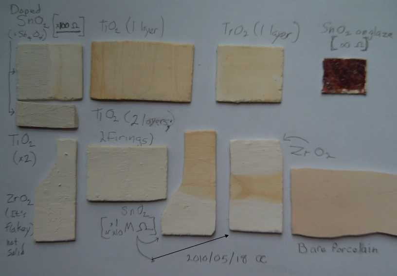
Experiments in firing/sintering bright white and conductive tin
oxide layers.
Finally, I found you have to dump out the accumulated lead
crap in an old lead-acid battery and replace the acid with water(!) as
part of the renewal process. I got good results renewing a "worn out"
car battery. I picked up a couple more small car batteries (~30 pounds)
to renew, to
have 36 volts for motor tests without dragging 50 pound batteries out
to the car and lifting them into a plastic box, which has been hurting
my bad back. The two latest were "sealed", that is, though they had the
usual vent holes, the tops were glued on. I found it was easy to drill
1/2 inch holes though the 'solid' part of the top and plug them with
small rubber test tube stoppers. On the 30th, I finally was able to
write up some
relatively comprehensive info and instructions for treating and
renewing lead-acid batteries, which I uploaded to the web site.
On the 31st I updated the motor controller manual, mainly
because the HTML editor had messed up the HTML code of last month's
version and wouldn't show some of the images. Since it
automatically messes up HTML you enter manually and it doesn't like the
exported HTML of Appleworks, which I originally wrote the manual in, it
has been frustrating. Hours are spent correcting the same automistakes
over and over, and then finding pictures still missing once it's
uploaded to the web site. There are a lot of programs out there that
automatically generate output code I would be ashamed to admit I'd
written, or written the generator for.
The Disgrace of the Patent System
the Need to rethink it
The patent system
was designed long ago with the idea that
when an inventor created something new, various companies would want to
use it, and that they would pay the inventor for whatever rights could
be
negotiated with him for cash or royalties, on an exclusive or
non-exclusive basis. If this scenario was ever valid, it doesn't work
at all today. For starters, the patent is a form of publication,
and everyone can see how the invention works without paying. That would
be good if they then had to pay to use it. In fact, most unsuspecting
inventors
patent, but less than one percent ever make good money by any means
from what they've invented. Only a lucky few got a salary while they
were working on it.
What actually happens in the best case with a valuable
invention is that the inventor is poor from having worked on the
invention unpaid, perhaps for years. It is cheaper for companies to use
the patent design and to fight the inventor in court - should he ever
eventually find
out
they've been using his invention and attempt to assert his rights.
The company(s) is (are) making good money from the inventor's work and
all their other products, and
they can drag out the court fight for however long the inventor can
afford it -- however many corporations are using it that he wants to
try
and fight. The invention is
adopted and the inventor either goes unpaid (best case) or is
bankrupted. (One local inventor I heard of last year had spent $70,000
so far trying to enforce his patent, with no end in sight.) Tesla
brought us the whole power grid with his induction
motors-generators and the theoretical basis for
radio, used by his one-time apprentice Marconi. Even with such
monumental contributions to
modern society, Tesla lived and died mostly in poverty, and was unable
to pursue later inventions. The
inventor of the intermittent windshield wiper spent the rest of his
life in court. Although through 50 years of persistence he won a good
settlement a few months before he died, he lost everything in life -
and he even had signed agreements with Ford Motors! Dennis Crumley, the
inventor of the golf bag with two wheels and a handle that you didn't
have to carry (1939?), a man I knew well, got nothing for
that. The list goes on and on. And it is not in a
company's interest to negotiate with the inventor: if they seek him out
and pay him
royalties while other companies don't, they are at a competitive
disadvantage.
In the worst case, the vested interests step in. These are
the handful of people making vast fortunes from the world as it
currently runs,
and to them certain types of inventions are threats. They have very
deep pockets
and
tremendous power, and they are unethical, unscrupulous and reactionary.
If an
enterprise
starts up
based on a patent product that threatens to change their world, they do
what they can to acquire the patent
cheaply, by any sort of dirty tricks (undercutting prices, cutting off
supplies of raw materials, misleading propaganda, bribes and worse...),
that
usually end up with the new enterprise quietly bankrupt, at which point
the
patent is theirs for a song. If all else fails, they'll buy it out (the
financiers were in it for the money - they'll sell), and
then shut it down or simply do nothing with it. (Why can't they be writ
with a bill of attainder
and be beheaded, their vast tainted estates/empires being used to
replenish the public treasury and their hoarded patents released to the
public domain? It seems a good safety fuse for
civilization - with or
without the beheadings. Action is long overdue.)
Once they have the patent, it is used to prevent anyone,
anywhere, from making the invention. It is used to suppress the entire
new technology. For example, no sane investor will look at
Chevron/Cobasys's
125 acquired
patents for marvellous, green, economical Ni-MH battery technology and
agree to help
fund a Ni-MH electric car
battery making plant, even if it will violate none of them. The end
result of a never ending court battle, an injunction stopping
production, and bankruptcy can be foreseen from the start. That's why
they aren't available in automotive stores everywhere today, at prices
competitive with lead-acid. Normally by the time
a
patent has quietly expired
in 18 years or whenever, the inventor and all those involved are long
gone,
and anyone who even remembers that such a thing can be made is left to
assume that since it was invented so long ago and yet has never been
used, it couldn't have been much good.
For example, this would appear likely to be the
fate of the recent compressed air engines, invented separately in two
countries at about the same time. There was also a plastic tank
invented which would make the compressed air safe to carry, by simply
ripping open rather than exploding if there was a problem. These were
all in the news with their enthusiastic inventors ("Now we can all
drive
without burning fuel!") about the
same time a couple of years ago - where are they now?
Small wonder China "won't honour" American patents and
says it plans to develop "suppressed technologies"! The wonder is why
the "free world" lets this situation persist, to the ruin of the
environment.
Today, patents are freely dispensed. It seems the
government will
happily take the money of anyone who wishes to patent most anything.
It incurs no obligation and provides no real service by doing so. Not
even a public attorney for the inventor if (when) industry illegally
appropriates his
invention. A musician has far more rights to his song than an inventor
has to his invention. Some
patents are now taken out by companies afraid that someone else will
patent what they're making, or are about to make, and stop them from
making it, even if
there's nothing very original in it.
The chief uses of patents today seem to be:
* to attract investors to invest in a 'proprietary' new technology
* to ensure no one else can patent what a company is already
doing and force it to stop as a business tactic.
* to prevent everyone from making or using a priceless new
type of product - suppression of technologies.
Note how little these business reasons have to do
with paying
inventors
for their special work, inventing, or ensuring that valuable
new
technologies are adopted
rather than smothered. An
inventor taking out a patent in hopes of thereby getting paid for
having invented is
wasting his
time and money - and worse: he's making his work susceptible to
suppression so no one at all can use it.
What is the answer? Here's my suggestion: I believe the
government needs to hold
and enforce all patents on behalf of the inventor and of society. If
patents can't be
bought up, inventions can't be kidnapped and murdered by vested
interests. The government
needs to collect royalties fairly from
all
companies that use the new ideas, the inventor getting his due, and
prosecute them for non-compliance, handling all court
challenges. In this way, companies will all be on a level playing field
and will recognize paying for use of inventions as a legitimate
business expense. Inventors won't be alone, abandoned, to match wits
with
established corporations with wily professional lawyers when (if) they
attempt to
collect their due. And the government should like it, as it provides a
new
channel of revenue - every adopted invention adds to the patent
royalties income.
The Electric HubcapTM
Vehicle Drive System
Minor Problems
Before I tested the "radial" torque converter on May 13th,
I gave the motor a free spin at full speed. One of the big 2" x 2" x
1/2" magnets flew off
the rotor! When I checked the magnet, I found that the nickel plating
had separated. The epoxy glue had held, but only the nickel skin
remained on the rotor.
Later, when I took the motor apart, I actually found there
were two adjacent missing magnets. With the other one the cause
was different: the epoxy glue had lost its grip on the smooth nickel.
(I never did find the second magnet.)
The obvious conclusion is the same either way: use epoxy
coated magnets and avoid
shiny nickel plated ones. They're usually cheaper anyway.
My instinct still says the magnets should be both
glued and screwed on for a final product regardless. While I'm testing
one
configuration after another on one rotor after another, I'm a bit
hesitant to spend the extra time, and to worry about sourcing magnets
with holes in them. (On the other hand, they'd be way easier to take
off a rotor if they were screwed on instead of glued.) However,
if the motor is going to lose these nickel giants, I'm feeling tempted
to drill screw holes in them. (ignoring the warnings not to drill or
cut them)
I continued the test anyway - the motor still seemed to
run pretty well. Then when I was testing the
torque converter with high thrust from the motor, one phase suddenly
quit. ay, yi - the motor controller? When at length I removed the
controller, I
couldn't find anything wrong with it.
Near the end of the month I
started repairing the rotor and improving it to prevent a repeat.
(Aside from reliability, I definitely wouldn't want to get hit by a
flying magnet!)
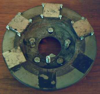
The rotor, motor side: two magnets flew off (two bits of nickel
plating from the magnet remain on the epoxy of one - I peeled most of
it
off earlier.) - new flat head screws helping to clip in the magnets -
I'll try
drilling holes in the replacement magnets and report on how that works
out.
Mechanical or Magnetic Torque
Converter Project:
Torque Leverage Without Gears
I started putting together the new "radial" (with or
without a "c") idea of torque converter. To make a long story short,
with everything arranged just right, it all fit together perfectly.
Not without buying and trying several ideas for pivot pins
and other headaches. I ended up using five 12mm wheel lug bolts. I
pounded them very solidly into the five lug bolt holes the rotor disk
happened to have. Even those thin-headed bolts just cleared (actually
improving the overall fit), and I also had to cut them 5/8" shorter.
I
also had to replace the link pin bolts holding the drum and axle
together with lug bolts - the nuts just stuck up too far inside the
drum. (Now the
threads on those "link pin" bolts need protecting - more work figuring
out how to set that up. For the moment I put some brass tubing over
them so I could run tests.)
I was at first thinking I needed bolts with a smooth
section for the arm pivot pins, but eventually I realized fully
threaded
would be excellent - even better, since the arms don't spin. Each arm
can swing back and forth, yet it's held securely on the pin by its
matching threaded hole. Simple! It can't slide up or down the shaft and
so there's no need for spacer washers, or nuts on the end. This is
fortunate since there
was no room for them.
I cut arms for the magnetic version from 1/2" x 1" steel
rod, drilled and threaded the holes, and screwed them onto the pivot
pins. Then I took 5 magnets and let them self-stick spaced around the
steel rim of the torque converter drum. It was hard but not impossible
to get the drum to turn by hand, lurching from one magnet position to
the next. I thought the motor will have to be pretty much floored to
get
it to start turning. Then I put in some screws to hold the magnets in
place.
The next question, as always, is: would those lurches be
enough to start the car moving? If the magnet strength is increased,
the motor won't be able to start. If they don't move the car, I'd have
to switch to trying the mechanical version with the arms shaped to
"semi-catch" and drag on the drum (via slots in the rim or pins just
inside). Luckily, much the same setup is required for either type - it
just needs new arms and a different drum-rim setup.
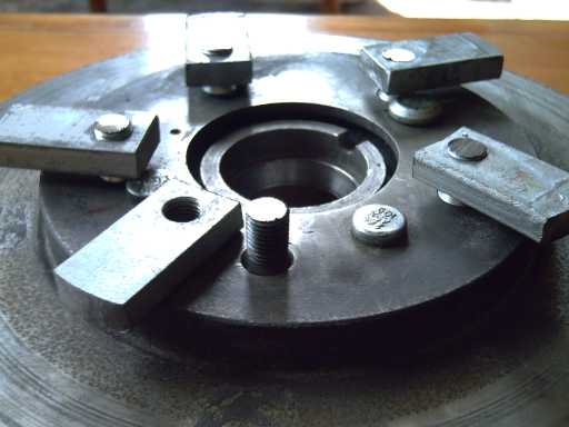
The five pivoting arms (front one is shown sitting beside its
mounting post)
When I tested it on the car
on the 13th, my first
impression was that the wheel seemed
to shake back and forth, that is in the direction of turning forward
and backward, but the car
didn't move. It should only be "shaking" one direction and hence
starting to turn, not both ways.
And it seemed to shake more at very low motor speed, but to ignore
everything and sit passively at higher speeds. Then a motor
(controller?)
problem reared its ugly head and prevented further testing and
observations.
A good point was that other than the back and forth
motion,
the strong vibration of the previous models seems to be gone - the
forces making it it have
been transferred from the (useless) axial to the radial (wheel-turning)
plane.
The motor seemed to have more than enough torque to
overcome the
cogging of the torque converter magnets. (Even with two of six magnets
missing!) That would
mean somewhat stronger
magnetic coupling could be used within the torque converter, which
would make some difference if not the difference.
To achieve that greater magnetic coupling, I could add a piece
of steel onto the end of each arm to thicken it, or I could narrow the
gap. There was about 0.2" of space between the ends of the arms and the
magnets in the rim of the drum, so I made new arms that were longer by
1/8". That reduced the gap to .075" and the attraction would be
considerably stronger. This seemed like the easiest solution and the
next thing to try out.
The other thing that was bothering me was the appearance
and likelihood that the converter was alternately trying to turn the
wheel opposite directions. I had expected the arms not to fly forward
soon enough to reach the next magnets until the pin was just about
opposite from it, but if as it seemed they reached the them too soon,
they would first yank the wheel backwards before yanking it forward.
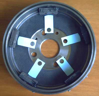
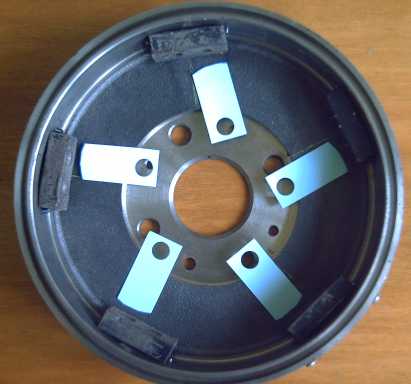
The rotor drum with the five magnets in the rim.
L: "At rest", the arms being pulled to the magnets. R: As motor turns
clockwise, the arms pivot to stay with the magnets, pulling the drum
(and car wheel) along until they lose their hold. The turning motor has
a leverage advantage with the pivot pins at a smaller radius, and can
pull the arms away from the magnets.
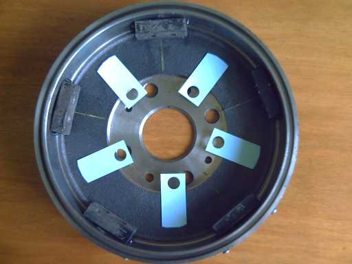
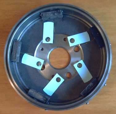
L: The arms theoretically swing out by centrifugal force. I hoped their
inertia and the time it took them to swing out would keep them there
until just about opposite the next magnets. R: What actually seems to
happen is that the arms swing forward and latch onto the next magnets
too soon, creating a backwards pulling force opposing the forward force.
How could this effect be negated? First I thought of
springs to hold the arms back until they were overpowered by the
magnets at about the right point, then small "retainer" magnets to
achieve the same thing.
Then a better solution occurred to me - a simple, positive
acting one using geometric forms. The magnets stick in from the rim
about .6". The arms stick out to within perhaps .7" of the rim. If I
screwed some metal blocks about .8" or .9" wide to the rim between
magnets, the arms would drag across them, unable to pivot out straight
by centrifugal force. The blocks could be sized to hold them back until
the inner ends of the pins were exactly opposite the next magnets, and
just
at that point the outer ends would clear the ends of the blocks and
swing out to meet the middle of the magnets - no adjustments or
guesswork, and no forces pulling in the wrong direction. There would be
little force acting between the arms and the blocks, thus little heat
and
friction. A bit of grease should suffice for lubrication(?)
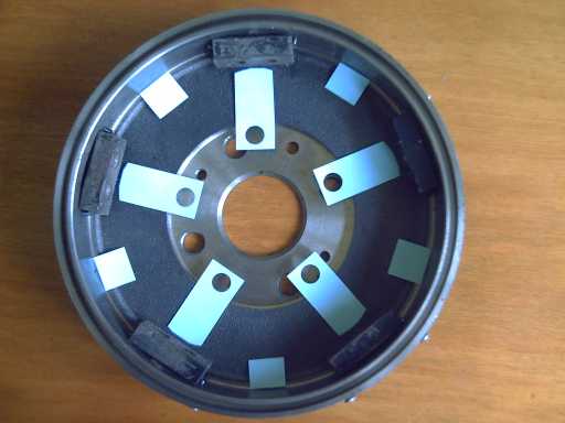
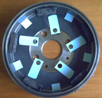
With blocks, "at rest" as before (L), providing clockwise torque as
before (R).
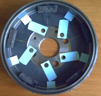
But in between magnets, the arms drag across the blocks. This prevents
them from swinging forward to catch the next magnet until the pivot
pins are directly opposite the magnets, preventing opposite-turning
forces. Yet it's symmetrical and will work alike in forward and
reverse.
The strength of the torque to the wheel depends on the
strength of the attraction between the metal arms and the supermagnets
in the rim of the drum. The torque required for the motor to start
turning depends on this and on the torque advantage between the radius
the pins are at versus the radius the magnets are at.
With no "bad
vibes" or counter turning forces, it seems to me this is (finally!) a
clear, practical design for
turning
wheels that should work well if the parameters are well adjusted: the
strength of the attraction, the pin radius, the drum radius. I was
wishing I had a larger
overall
drum - the brake drum is 10" diameter or 5" radius, but the side walls
are 1/2"
thick leaving 4.5", and the magnets stick out over 1/2", leaving under
4" effective
torque radius. If it seems close or barely works when I test it,
maybe I'd cut slots in the rim for the magnets and have them flush,
and make a third set of arms, another 1/2" longer.
Or maybe I'd go
back to that 12" aluminum frying pan I was trying to figure out a
workable
design for at the beginning of this whole project! (Hey - it fits
nicely!)
I later decided that's what I'd do: the length of the arms
from the pivot point would go from 1-5/8" to about 3" - double -
improving the motor's leverage on the drum. (and here I had just made
the new, slightly longer, arms, and not even tried them yet!) I can
also get a look inside around the outer edges and how it all fits; with
the brake drum, everything was so close I couldn't even squeeze a
dental mirror in to have a look. The light aluminum pan instead of the
heavy brake rotor also drops about 8 pounds from the unit. I hope it'll
take the stresses. Magnetic will have a lesser level of them than a
mechanical design.
In lieu of curved magnets, I decided to cut the 1"x2"
supermagnets each into two
1"x1" magnets, both sitting more flushly at the outer rim, with a small
"fold" in the middle. I can't get the gaps too close as the pan isn't
very round (whereas the brake drum is 'perfectly' machined on a lathe),
but this should effect some improvement. There's warnings not to cut or
drill the magnets, but I cut the jagged end off a broken one recently
with the
angle grinder/zip disk and it worked fine. The reactive neodymium
causes a bright arc instead of the lesser sparks one usually sees when
cutting steel. The cut faces are much less magnetic than the others:
although I tried to minimize the heat, the metal loses its magnetism
with the heat of the abrasive cutting wheel, perhaps for 1/16" or 3/32"
of an inch in from the cut.
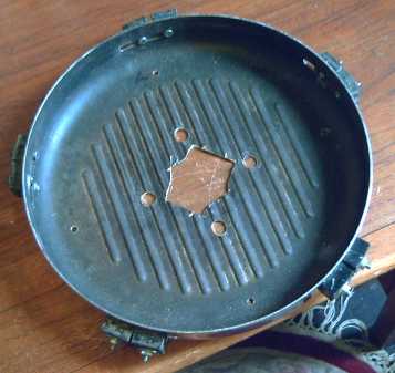
First I mounted the magnets on the inside of the rim.
Then I realized that the 12" aluminum pan was practically non-magnetic,
and that an extra 1/2 inch of radius could be gained by putting them on
the outside.
It's now about as big as the 13" car wheel allows -
any larger and a flat tire would cause damage, with the rim hitting the
road.
When the motor (and controller?) is (are) repaired, the
arms and
between-magnets rim blocks will be cut out, drilled and assembled. And
then... well it's all in the test.
Unfortunately for this long dragged out project that you'd
think would warrant a payed design team, I got a great idea for
a solar cell electrode that seemed to merit my attention, and it got
neglected again for a couple more weeks.
The failures and delays are vexatious, but of course the
end result is what counts, and if - when - that's a light, practical,
virtually lossless unit that
can replace heavy, crappy geared transmissions,
it's worth however long it took.
Nanocrystalline Ceramic Motor Coil Cores Project
Here's another "pie in the sky" potential advantage to
nanocrystalline ceramic coil cores: The magnetic
permeability of known nanocrystalline alloys and composites can already
be
higher than for solid
iron and alloys, and the field is new and poorly explored, especially
the ceramics area. This being the case, there may be good possibility
of creating a nanocrystalline soft magnetic ceramic glaze with a
permeability
high enough that "supermagnet strength" fields can be created in an
electromagnet without the excessive current and consequent overheating
of the coil and the driving electronics that would cause burnouts.
That could create the situation I'd
originally envisioned when I started this whole project: Supermagnet
strength magnetic fields would attract and repel each other at close
range. An Electric Hubcap type motor would have tremendous
torque. It might be high enough torque to turn the car wheel
directly - no gears or torque converter. Far-fetched? Maybe. Do doubt
so were
permanent magnet supermagnets, until somebody discovered the right
formula. (Naturally I'll continue development of the torque converter
until and unless this proves both successful and practical.)
Any major increase in available torque per amp from a
stronger field would lead to better performance and much lower losses,
perhaps reducing the required motor size and weight for a given
horsepower. That includes not just virtually eliminating core losses
but some reduction of copper losses.
(Please note that such
improvements, however fabulous, do not provide "overunity" efficiency,
"free energy" or "perpetual motion". The energy needed to do the work
is still drawn from the batteries - only the extra amount needed to
overcome inefficiencies drops.)
I didn't explain earlier why I chose "Laguna B-Mix" cone 5
porcelain clay: Glazes soak into the underlying clay, and also draw
materials out of it during firing. Water soluble glaze materials will
soak into the
clay, and
then there's a lower proportion of them in the glaze than as mixed. So
what
you apply glaze onto is quite important.
Unlike ceramic, porcelain, once fired (vitrified) at a
high temperature, isn't porous. The glaze is fired later at a lower
temperature that will leave the porcelain more or less untouched. The
pre-fired porcelain
will let the solubles dry in the glaze without 'migrating' (allowing
the use of soluble glaze substances), and help keep the mix interface
zone to a minimum. (The choice of "cone 5" porcelain is because that's
almost as hot as my mini-kiln gets.)
Since I seem to have obtained the basic METGLASS structure
- crystals embedded in an amorphous glassy substrate - it seemed worth
while to try playing with the mix some more. Probably the coarse FeO
wasn't a good way to add iron, and perhaps ilmenite wasn't a good way
to add either iron or titanium. In fact, seeing those big crystals, the
FeO may not have changed much in the firing - except perhaps around the
edges.
To 50 g of "glaze mix 3" (See TENews#27) I added 5 g
sodium silicate, 2 g
laguna borate and 2.2 g Fe2O3 to make "glaze mix 4". The last is very
fine (stains everything red!), quite unlike the grainy FeO and Fe3O4
that I have, and the final oxide product is after all dependent on
reductions and oxidations during firing.
If the ferric oxide had any magnetic effect commensurate
to its overpowering red-brown colouring effect, it should be great! I
painted it mix 4 onto some new porcelain chips. No magnetic result.
Then I added 3 g of TiO2, a notorious(?) whitener and
glaze
matteing agent as well
as being the other ingredient for getting barium titanate. (Glaze mix
5... At this rate I may get up to
mix 40 like water displacer "WD".)
According to a pottery book, TiO2 "easily goes into a
microcrystaline
state with many glazes. On a
vertical surface these crystalline forms often turn into streaks like
animal fur." This is rather exciting - perhaps with the melt-quench
technique, those microcrystals should become nanocrystals?
The
colour became a pastelly red/brown/pink, and dried to brown. The book
also says it will
"often pull small amounts of iron from the body or other glaze oxides
and create a synthetic rutile". The colour seems reasonable for that.
(It might also perhaps "pull in" some barium to form the barium
titanate?)
The glaze
could be applied
quite thickly, but then it crazed and came loose in clumps as it dried
- wait, I haven't even put it in the kiln yet! I expected it to flow
smooth
during firing, but it stayed clumped up in "islands" with with bare
gaps between.
Whereas mix 4 looked great, glassy, this was in fact, the un-flowingest
glaze I've ever seen and it didn't look glassy. More of a flat black.
All from 3 grams of
titanium oxide? (~6%) At least the fired glaze stuck to the porcelain!
I fired it for 85 minutes, which should have reached about
1900ºF. Perhaps the titanium raised the melt temperature needed to
attain the glassiness, and to flow?
The next thing to try was to heat it longer, say for 100
minutes, which should have hit 2000ºF but only bent the "02" cone
(2003ºF) slightly. Counterintuitively, instead of spreading, it
seemed to have intensified the beading - smaller, taller islands with
more space between them. No magnetic core effect, not attracted to
magnets, and this seems awfully hot for what I think should be a low
fire glaze. The FeO loses its attraction to magnets up here (probably
becoming Fe2O3).
(If none of my cores have been magnetically better than
air... well, none have been worse, either!)
TiO2 is noted for forming 'microcrystals' unbidden, and at
40 x magnification I observed tiny needle-like crystals within the
clear glaze. Those would
have to be the ones, that might well turn into "furry" streaks if the
glaze
flowed. Why are they so big that I can see them after the melt-quench?
There seemed to be more after the higher
temperature firing. So what about a lower temperature firing? Would
that bring them down to "nano" size? I still had enough porcelain for a
couple more sets, and plenty of glaze mix #5.
I fired 70 minutes, which reached about cone 07,
1775ºF. It was still weakly attracted to magnets, and it lacked
the glassy sheen of the higher temperatures. Magnified, small "blobs"
of unmelted glaze material were visible, like undercooked pearl
tapioca. Microcrystal needles of TiO2 were mostly smaller, at the edge
of visibility - the "are those what they seem to be?" size. That could
indicate that there are nanocrystals. But by the other features, I'd
guess that it wasn't hot enough ...but it still all beaded up! The
coil's magnetic field was as usual no greater than for air.
It seemed it was time to move on to a new glaze mix, #6...
this
time,
no grainy FeO, no ilmenite. Instead, the pure Fe2O3 and TiO2. At least
the TiO2 was making discernible crystals.
Now someone has sent me a link to reducing Fe2O3
nanocrystals to Fe3O4, with fatty acids from soap and vinegar! (http://opensourcenano.net/ -
their one and only project.) Does this fit in somewhere?
Glaze mix 6:
Glassy
Sodium Silicate: 50g
Laguna Borate: 25g
(Composition of laguna borate:
- B2O3 27.5%
- CaO 18.9%
- SiO2 18.7%
- Al2O3 8.1%
- Na2O 4%
- MgO 2.3%
- K2O 1.4%
- Fe2O3 0.1%
- ?? 19%
...seems the first mixes weren't missing the CaO after
all. I
think I'll skip adding more "K" as there's so much "Na" in the sodium
silicate anyway.
)
Metallic
Fe2O3 (rust-iron): 10g
BaCO3 (barium): 1g
TiO2 (titanium): 3g
CuSO4 (copper): 0.35g
Glaze 6 was smoother, but bubbled up and broke in spots.
(I
think the thick glaze must have been still wet under the surface.) No
magnetic
effect, not attracted to magnets. Sigh!
I decided to add 2g of lead (litharge, PbOx),
which is a good glaze flux though it's seldom used any more as such -
the pottery supply doesn't even stock it. But I have some - cleaned
out of lead-acid batteries. I sifted the clumps through a #60 screen,
and it all crumbled and went through. Lead oxide is however available
in frits (fine ground
glass mixtures), which is a
safer form to deal with (other than silicosis from the dust): with at
least 2x more silica than "leadia", the lead
becomes inert and so the frit is non-toxic.
At the same time, I added
2g of
zircon, and 2g of potassium chloride to fix the "potash
shortage" (Chloride... oh yeah, I can use
water
soluble forms!)
I also added 10g of sodium sulfate, to liquify it
again. (Glaze
mix 7.) It
wasn't really enough - it was still pretty dry and lumpy. But I don't
want to add much water with the soluble substances I'm using - they
might migrate to the bottom or the top. Oh well, it makes it hard to
paint, but even dry lumps sitting on the clay should melt and fuse on
in the kiln. (...Still reading pottery books: seems you can use
glycerin, propylene glycol, liquid laundry starch or other things as a
glaze base in order to avoid adding water to them.)
I fired it to 1050ºc. (which I actually measured with
the thermocouple. It was definitely glowing red hot and lost its
insulation, but it works - perhaps I should just get a couple more of
them and ditch the lower temperature pottery cones. 1050 c = 1922 f =
cone 04.) That's about 80 minutes for my kiln, and just over the median
temperature for low-firing glazes. Then I quenched the wafers with the
melted glaze in hot water. (marginally less thermal stress than cold
water?)
This structure of this batch seemed quite successful: It was a
smooth and clear but dark glaze. No needley microcrystals
of titanium
oxide, or other grainy bits, were visible, which should hopefully mean
that the titanium et al had nanocrystalized. There seemed to be some
micro-fractures in the glass, "crazing" on a small scale (probably
inevitable with a melt-quench).
Unfortunately, the
magnetic result still appeared to be nil.
So, here's a wafer of porcelain with great
transparent, nanocrystalline glaze, with no particular magnetic
properties. Along with asking what's wrong, let's also pull a "post it
notes glue" trick and ask "What is it
good for?" The surprise answer is the title of the next project!
Nanocrystalline Rear Electrode for Dye
Sensitized Solar
Cells
I really didn't want to get sucked into starting yet
another energy project with several unfinished ones dragging along.
Yet, obtaining this transparent nanocrystalline
glaze form gave
rise to the idea of using it for the rear electrode of a
nanocrystalline titanium oxide/organic dye type of
solar cell, and like the other projects, the fabulous potential of this
idea
just makes it impossible to pass it up.
These cells use a photosensitive organic
dye, impregnated into a surface layer of
sintered nanocrystalline titanium dioxide (pottery supplies shop).
There are instructions for
making the basic cells on line as a school lab exercise(!), with (eg)
blackberry juice as the organic dye. (Obtaining all the listed
ingredients of that lab exercise has however proven to be a major
challenge.)
Evidently TiO2 is a P-type "wide bandgap semiconductor". A
photon comes through the cover glass and zaps the photosensitive dye.
An electron from the dye enters the TiO2, which
carries it a short distance to a transparent, much more conductive,
layer on the cover glass, and hence to the negative terminal and the
external circuit. The electron has to have enough energy to provide the
voltage to jump the "bandgap" before TiO2 will conduct, and that's
where some of the voltage of
the cell is derived.
An electrolyte supplies an electron to restore the dye.
The electrolyte ion diffuses over to the positive rear plate and picks
up another one returning from the external circuit.
Layout of the front plate seems to have a pretty
"standardized" form: glass (or transparent plastic), a transparent
conductive layer (connected to the negative terminal), then the layer
of white titanium dioxide with photosensitive dye. Behind that is a
liquid
electrolyte separating it from the rear, positive, plate. In structure
it's much like a battery.
The
rear plates vary greatly. Some incorporate a bright white
reflector surface to reflect light back out, but much of the light that
passed through the dye is at wavelengths or polarizations the dye isn't
sensitive to, so it goes right back through again and the improvement
is only around 10%.
Here's the potential advantage of a
nanocrystalline glaze rear-end: The photons passing
through the dye hit the rear electrode. They strike nanoparticles in
the glaze and are converted to other wavelengths, or pass by chiral
molecules and are repolarized. With a bright white
underglaze layer on the porcelain, the light reflects back towards the
front and the dye, after having been modified.
Thus the amount of light energy actually converted to electricity by
the dye could perhaps be as much as doubled, making, eg, 20% efficient
solar cells instead of 10%. This would cut the cost per watt
for solar collectors, along with reducing the area that needs to be
covered to obtain a given wattage.
Various types of rear electrodes can be tried and compared
with identical front sides to see if this advantage is real, and how
effective it is. That will be the essence of the project at this point:
to study the cell's increase in effectiveness with this backplane and
try to optimize it,
rather than to try to create practical solar cells in all their aspects
myself.
Now down to details. My nanocrystalline glazed wafers are
in essence virtually the finished product! The only essential
components they don't already have are a bright white underglaze layer
(more TiO2 - "titanium white", or perhaps zircon or tin oxide or a mix)
and a transparent, conductive layer
applied to the top of the glaze to connect between the electrolyte and
the
external circuit.
This magical sounding transparent
conductive layer is tin oxides - mixed SnO2 and SnO, preferably
doped with antimony oxide, and there
are instruction guides
on the web for two ways to make this layer on a glass(y) surface. One
method needs methanol and other things while the
other is very simple - basically just heat the glass with the
chloride powder sitting on one edge. Finally I noticed the difference:
the complex
method used tin (IV) chloride and
the simple one used tin (II) chloride, stannous chloride (pottery
supply - or make it: Sn + 2HCl ==> SnCl2 + H2). The
individual who posted the easy method, complete with photos, read it in
a 1969
article in Practical Electronics magazine, and has all
kinds of very interesting projects on his web site.
(http://www.teralab.co.uk/) The
other seems to originate from someone
at U of Wisconsin.
The resistance of the simple method's deposit was much
higher - x 1000 ohms versus x 10
ohms or even x1's - but perhaps that's simply a matter of adding
successive layers, and-or doping with antimony, techniques used in the
complex method.
The next substances required in the plans that are so
freely
available on the web are iodine and potassium iodide for the
electrolyte. Here again I run up against Canada and BC's abusive
maze of
substance laws. A drug store seemed a logical place to get iodine.
Turns out a
compounding pharmacy does have or can get potassium iodide and iodine,
but isn't allowed to
sell me any of either without a doctor's prescription. They have
"tincture of
iodine", which contains 2.5% potassium iodide and 2.5% iodine (but no
prescription needed) - great, except for the 95%
impurities.
I asked the pottery supply to try to get me some of either
or both at Seattle Pottery Supply, along with
more laguna borate and the stannous chloride. The only thing I got was
the stannous chloride. There's no chemical
store in Victoria and placing an order with a lab chemical supply
company always seems to run into hundreds of dollars - and even then,
will they be permitted to sell me the items I was
unable to buy elsewhere?
BTW: I thought, why use tin chlorides at all? Why not just get
the
oxides themselves and sinter them on? It ends up as the oxides anyway.
But! It turns out stannous chloride dihydride melts at just 37ºc,
and the anhydrous form at 247ºc. SnO (without a "w" on the end)
decomposes at 1080ºc, and
SnO2 melts at 1630ºc. Even if I
could get the kiln to 1630ºc it would wreck the SnO and the glaze
or
glass I'm applying it to
(not to mention the porcelain and the kiln), whereas
300ºc is no problem, so using chloride seems like the way to do
it. (I'd already melted a couple of pieces of glass sintering TiO2
onto them.) Metallic tin melts at a good temperature, but it
would bead up,
whereas the chlorides seem to sheet out over the surface, and the
resulting
oxides are evidently well bonded to the glass - not a trivial
consideration.
The first apparently successful glaze was mix 7 fired at
1050 degrees. That might well be "good enough" for some good results,
but doubtless it could be optimized for the job. I think I could add
more titanium and get a more nano-matte finish, which I think would let
more light in and out of the glaze from the front. The amount of lead
and other metal oxides to add to effect whatever light modifications
work best could perhaps be fine-tuned spectroscopically.
So I added 1.5g more TiO2 to the mix. As some of the mix
had now been used up, that's probably equivalent to about 2g in the
original mix. Then found I could buy glycerol at the drug store without
a prescription, so I added 5g of that to liquify the glaze better.
Glaze mix 8. It had become quite lumpy and it was hard to break up the
lumps. It was nothing like smooth when I painted it onto four wafers of
porcelain. It worked better if I wetted the porcelain with some before
I applied the glaze. But the glycerol burned and stank, and blackened
the pieces. Enough of that! I shut off the kiln.
I ordered a mortar and pestle from the drug store for
later use. But perhaps it would be best (except for the dust problem)
to mix all the dry ingredients and only add sodium silicate to the
amount I need for whatever batch I'm about to paint. There's more on
the
whole subject area of glaze problems and defects in the pottery &
glaze books, that I hadn't paid much attention to.
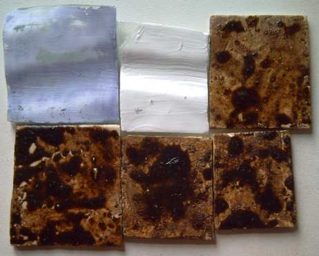
Glaze 8, rather matte and very lumpy.
Also: TiO2 sintered onto two pieces of glass.
The left one was stained with blackberry juice and then wiped.
Although sintered to above the specified temperature (the glass even
sagged),
it's powdery and wipes off.
(Later I tried high temperature borosilicate glass (wood stove door
glass), heated to 1800ºF.
The glass fared quite well, but the the result was still powdery.)
Once fired, those were as splotchy as other recent
glazings - no surprise. I may have the essence, but there are some
details to be worked out. Then just as soon as I had those fired, I
underwent a small realization in my thinking. Whereas I had been trying
to make thick glaze attempting to produce as much magnetic material as
possible, I suddenly realized a thin glaze to let the most light pass
through both ways might be best.
Also, I'd been trying to think how to get the back
of the cell to reflect as much light as possible. There was no way to
stick a mirror or a metal in between the glaze and the porcelain. Then
it hit me: Titanium White! The bright white, opaque titanium dioxide
could be painted on the porcelain as an underglaze as a matte 'mirror'
before applying the thin main glaze. Zircon or tin oxide underglazes
can also produce bright whites. That way, most of the
light would be reflected back out as well as lengthened in wavelength.
Here's one key to twice the solar conversion efficiency.
The cross section of the cell is thus:
- anti-reflection coating layer
- glass
- transparent conductive tin oxide layer ("-" electrode) on the glass
- dyed, sintered titanium dioxide semiconductor layer (photosensitive)
(or tin oxide? - several better properties - pick a
different dye, different electrolyte?)
(dyes?: blackberry juice, tartrazine?)
- electrolyte (KI:I2, or ??? In our "free country", the
elementary chemicals KI and I2 evidently can't be had without - ahem -
a doctor's
prescription.)
- transparent conductive tin oxide layer ("+" electrode) on the glaze
- transparent nanocrystalline light modifying glaze layer
- bright white reflective layer (white underglaze)
- porcelain back.
I painted TiO2 wetted with water straight onto porcelain
wafers, no glaze, and fired them to 1050ºc, same as the glaze. I
quenched one and let the other cool slowly in the kiln. I couldn't see
any difference when magnified - they were evidently both the same. The
surfaces were hard, unlike my attempts to sinter TiO2 onto glass at
lower temperatures, where
it seemed to remain a powder.
The brilliant white of the raw TiO2 gave way to a duller
somewhat yellowish color. I think it had become rather transparent and
was transmitting the color of the porcelain. So I decided to try
thickening it. I did a few more wafers, and on a fired one I painted a
second layer. (I discovered later that the glaze didn't stick if there
were two layers, but that one layer seemed to be brighter after
glazing.) At the same time, the glaze books had mentioned 3
'opacifiers' - TiO2, SnO2 and ZrO2. I painted on test areas with all
three (mostly over an unglazed, painted TiO2 layer) to see which one(s)
seemed whitest.
At the same time, I also added a little Sb4O6 to the tin
and painted on some with that. (Not measured - several %.) The doping
(hmm... why would it actually mix?) had a separate purpose: If I could
sinter a layer of tin oxide directly onto the glaze surface as part of
the glazing step, I could probably get a very good and highly
conductive layer of nanocrystalline SnO2 with a very large surface area
to interact with the electrolyte. It seems platinum is usually used as
a catalyst here for best results (hmm... the "lab exercise instructions
used graphite), but perhaps tin oxide with lots of
surface area could make that pricey element (and can I actually buy it
anywhere anyway?) superfluous? Or maybe a different electrolyte
wouldn't care for Pt?
Results from this firing:
* the titanium oxide was much brighter with a second layer on a second
firing. Still not "paper white" like it is before it's fired, though.
* The zinc oxide still rubbed off as if it had never been heated.
* the tin oxide sintered nicely on the porcelain, though it could still
be scraped off.
Electrical resistance was in the megohms to tens of megohms range.
* the tin oxide doped with somewhere x1's of %'s of Sb4O6 looked about
like the pure tin, but the electrical resistance was in the x100's of
ohms, a 10,000 times improvement. (I may have painted the layers
thicker,
too, but I don't think that's the main change.)
* A SnO2 layer heated on top of glaze became transparent, and also lost
all its conductivity, having evidently soaked up insulating glass/SiO2
from the glaze. This means it can't be done by a hot firing with the
glaze, and we must go back to the SnCl2 method of applying the tin
after the glazing to
get a conductive layer. (I may experiment further with this, though.)
* If only the dye could be put right into sintered tin oxide instead of
the low conductivity titanium oxide?
* I wonder what sintered PbO would be like?
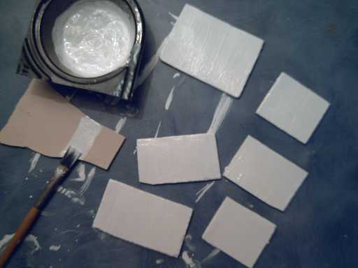
The raw TiO2 is bright white!

I wanted to try sintering some more TiO2, hotter than
before, onto well supported glass, but I left it out of this hotter
firing as I was afraid it might entirely liquify and wreck the kiln
floor. It had to wait for another, shorter, firing. (25 minutes.) The
purpose was to explore putting the dye in sintered tin oxide on the
glass, just in case that's optoelectrochemically feasible. Later I read
a paper that says it works, but not as well as the TiO2. But it seems
the problem relates to the electrolyte - that if the electrolyte was
faster, a better conducting substance could be better.
(But the TiO2 is just so bad... perhaps it can be
doped with something to produce an "optimum" conductivity, or a mix of
titanium and tin oxides could be used. The paper mentions several
oxides, but not the idea of mixing or an intermediate resistance.)
And what about that idea of a faster electrolyte? Is the
3I- ion unique, or are there other electrolytes that might work? What
about bromine & bromide, for example?, lighter halides. Is there a
3Br- ion to effect the same chemistry? Hmm... not that I can find. 3I-
does appear to be unique. Also, looking up bromine, which is a liquid
at room temperature, I see it boils at just 59ºc, a temperature
that might easily be reached in a solar collector, and that even below
that its vapour pressure is high. The cells would have to be well
sealed.
When I took the glass out
of the kiln - still pretty hot - after a moment a couple of flakes of
the tin jumped off. Before I could even react, almost all of it
flaked off.
What was left said megohms, even though it had the antimony
additive.
It might still be done by putting a layer on as chloride,
which would be well stuck and low resistance, then painting oxide on
and sintering, which would make oxide on oxide - that would probably
stick.
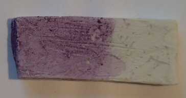
Porcelain with sintered tin dioxide (Sb4O6 doped), partly blackberry
dyed.
Resistance was only hundreds of ohms, far better than the titanium.
Another thing to try would be to mix the tin oxide for
sintering with a clay slip on top of the glaze (I'll use Vashon paper
clay), to prevent it from absorbing glaze and becoming an insulator
during the firing.
I decided it was time to abandon the lumpy glaze and do a
new batch. This time I'd mix the dry ingredients and only add sodium
silicate to a little when I went to use it. But what about those big,
lumpy, copper sulfate crystals? They needed hours, at least, to
dissolve. Here the mortar and pestle I got at a pharmacy.
(For some reason they were permitted to sell me one without a doctor's
prescription.) Yes, that ground some up quite fine rather nicely! It
seemed to miss a little around the edges which I had to push towards
the center with a stick to mash, so I ordered a smaller pestle as well.
Glaze Mix 9
- Laguna Borate - 25g (composition - see mix 6)
- Fe2O3 - 8g
- BaCO3 -2g (oops - meant to add 1g; extra spilled in)
- TiO2 - 4g
- PbOx - 2.5g ("litharge")
- CuSO4 - .4g (hmm... why am I using this if it's not to be magnetic?)
- ZrO2:SiO2 - 2g (zircon)
- KCl - 1g
These were mixed dry in a jar. For each painting job, a little is
dumped out and enough sodium silicate is mixed into that to wet it for
brushing on.
For the front electrode I had been trying to get the transparent
conductive layer of tin oxide on the glass with poor results. I finally
realized the the "easy" method was employing the vapours given
off by the tin chloride as the coating, not the tin chloride placed
directly on the glass. I decided part of my problem might be the glass
itself. First I tried a microscope slide glass, which turned out to be
plastic. It certainly didn't like heat! Then I exchanged the regular
greenish
leaded window glass for some high-temperature, yellow-brownish
borosilicate glass ("pyrex" - fireplace or woodstove door type glass).
5mm thick, but it was available.
A second advantage of this type was that it seems to
transmit
light more transparently. (This is just an impression.) Thus if "bad"
light passed right
through the dye, it would be then altered by the leaded
nanocrystalline glaze layer behind, perhaps changing it to "good" light
to be reflected back through the dye, rather than changing very
much from "good" to "bad" just before the light first reached the
dye.
As the month draws to a close, I'm not satisfied with
brightness of the reflective white underglaze layer, the consistency of
glaze thickness, and the high resistances of the tin oxide layers, and
I don't have an antireflective coating on the front glass. However, I
do have test electrodes that should emit electricity in light.
The only one thing that's missing for working test cells
is electrolyte - the iodine and potassium iodide. I suspect that even
if I went to
my doctor, I would find there's some law against him prescribing
something for a non-medicinal use, or that even in the absence of any
specific law he'd be afraid to do it. What's next? Spend a year or two
figuring out how to purify iodine from seaweed? It seems a serious
diversion from a project otherwise ready to test. Maybe one of
those chemical companies where placing any order usually costs hundreds
of
dollars will sell me some. Or maybe not.
What other electrolyte might there be? The
iodine/tri-iodide chemistry is pretty unique and not duplicated by any
of the lighter halogens. But what about zinc oxide? There's that nasty
zincate ion that messes up recharging of nickel-zinc batteries... that
would seem to
be
along the right lines. But what would it be
dissolved in? ZnO isn't soluble in water. How about a solvent?
Turpentine? Toluene?
Thought: Parking a car in the sun all day with over a square meter of
20% efficient solar
panels on the roof could provide some people with
enough battery energy to drive the car home in the evening, without
plugging in the car. This would of course generally work better in
California than in BC in the winter.
Ocean Wave Power Project
A newspaper columnist wrote favourably about the Site C
Dam project, which
inspired me to email to him about west coast wave power at 1/2 the
capital cost without flooding a valley... and then to revisit the
website of the Danish wave power unit that I'd mentioned in 2008
looked quite similar to mine.
It seems there must be more support for wave power
in Denmark than in BC. His technology, so similar to mine, won a "clean
energy" prize from a government ministry - perhaps that came with
funding attached. Anyway, he now has some sort of contract for a larger
prototype.
This "1/5 scale pre-production prototype" design
is now almost the same in principle as my 2007 design that I
showed that October to an ocean power official at the BC Ministry of
Energy.
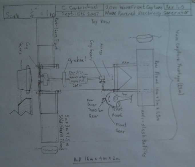
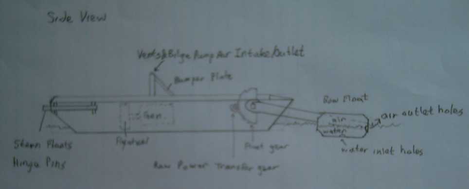
My 2007 Floating Wave Power Vessel design concept

The Danish design concept 2010
The
differences are first that he didn't bother with rear side floats,
behind and
beside the main "hull", and second that instead of a main hull per se,
he has transverse floats front and aft with a platform between them.
Since in my mind I've adopted his transverse floats for any future
units, the convergence of design is marked. I feel rear wave capture
floats left and right extend the meters of wave front being captured by
each vessel and its mechanisms, and spread out the portion of the wave
cycle over which the
power is developed. There's one
other big difference: his is being built; mine isn't.
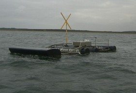
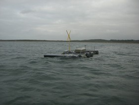
Danish prototype test. Note the up/down movements of the wave capture
float
at the front: almost out of the water on left, mostly submerged on
right.
One feature I plan differently is to use ferro-cement
construction with floatation foam: low maintenance and almost
indestructible and unsinkable. Of course, his is a prototype and he may
also have such materials in mind for full scale units, seeing we seem
to see so much eye-to-eye.
http://www.dexawave.com/
I would hope I could have been at least where "Dexawave"
is now
a
couple of years ago if I had got funding and provincial participation
in 2006 or 2007 - I would hope to have been putting power to the grid
at least on a test basis, or to isolated communities not on the grid.
But in
January 2008 I started the car motorizing projects and became rather
uninclined to pursue wave power as my main or sole preoccupation. The
province failed to "strike while the iron was hot", as it were. As it
is, I
hope to find time for my "proof of concept" prototype at some boat
launch this summer. But at some point, if it
just ends up I'm doing virtually the same thing as somebody else who
has project funding, and who has been able
to narrow my lead and then forge ahead, at what point is it not worth
bothering with?
The same BC that didn't have $5000 for one of its own top
inventors in 2006-2007 may soon spend a couple of billion dollars
buying
similar
units from Denmark or Germany along with everybody else with suitable
coastline, instead of
being the leading exporter. And then ask itself why it just finished
flooding a huge valley on the Peace River and building a tremendous
power line, when it can more easily make the power it needs right where
it's needed.
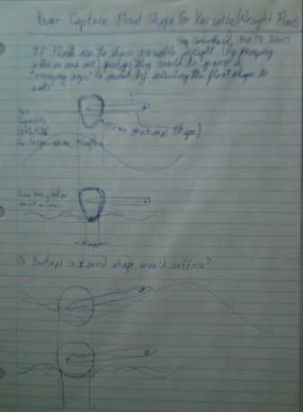
Float shapes for variable mass for variable wave sizes: thinner at
the bottom. There's a lot of room for experimentation and comparative
measurement testing here.
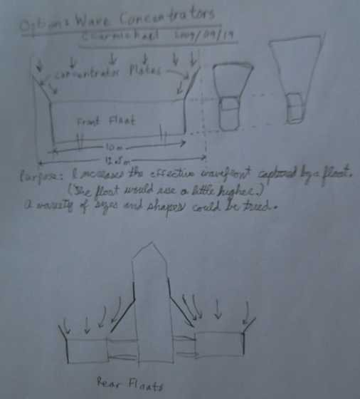
Wave concentrator idea to get a little more out of a given size
float.
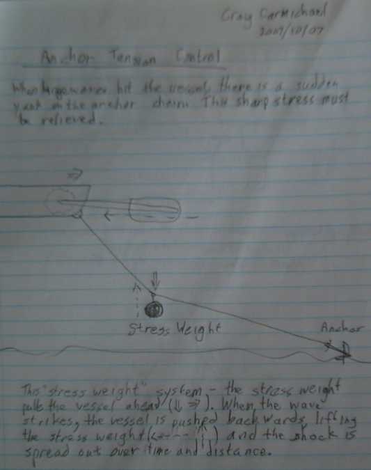
Anchor strain relief weight idea to prevent anchor from being tugged
across bottom during storms. I've learned since that this is often done
similarly but with a float in the middle of the line instead of a
weight. Both weight and float might be even better.
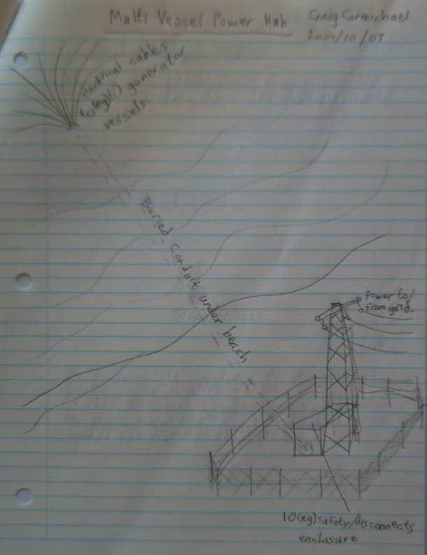
This is the part that's very hard to do without the province
actively on side: anchor the vessels offshore and connect them to the
power grid.
Turquoise Battery Project
No time to work on it!
Lead-Acid/Sodium Sulfate Battery Renewal
Project
Sodium
Sulfate for Battery Renewal (Click for Prices, Info.)
It's
in the
Dump: Key to rejuvenating old batteries?
On April 30th I dropped off some samples of sodium
sulfate
product at Canadian Electric Vehicles and in the conversation got the
scoop: As the plates gradually corrode, they give off dust. (lead
and-or lead
sulfate
and-or lead oxides) The powder accumulates on the bottom until it's
touching
the bottoms of the plates, and at some point, it shorts one of the
cells. A battery with more bottom depth under the plates will last
longer before shorting.
So the first difference between the successful technique
and what I'd been doing would be that they dump out the battery,
getting rid at least some of the crap
off the bottom,
and often specifically
clean it out.
The other difference is that
whereas I've just been adding the salt, those using alum ditch the old
acid entirely and replace it with just water and the sulfate salt. But
what's
wrong with the acid? It seems like perfectly good acid. Why bother
getting rid of it when the battery needs acid anyway, and this is acid
it already had in it?
But I finally realized that this step is critical. In an
old
battery that won't "hold a charge", I expect much of the
sulfate is attached onto the plates as lead sulfate and isn't in the
liquid. Having the salt initially with no acid is vital to the the
cleaning process. The sulfate on the plates will turn back into acid as
the plates are cleaned and
the battery charges, and when the battery is discharged down to having
no acid left, the rise in pH starts the cleaning reactions. If you
leave the "excess" acid in it, it doesn't get that pH rise when it's
discharged to desulfate the plates.
I tested these procedures by cleaning out a battery that
had two
shorted cells that nothing else had fixed. A battery repair person said
that once a cell was shorted nothing would restore it. That sounded
like a challenge.
One of the cells seemed to un-short but the other was
obtuse. After leaving it for a few days, I tried blasting it with a
high charge. That brought the voltage up to about 16 - obviously all
cells had voltage, and I removed the charge after a few seconds, having
previously found continuing to blast once the voltage was up was
counterproductive. But the voltage quickly dropped back to 10 and
wouldn't jump to 12 again. I left a charge on it, which soon brought it
back down to 8, and it didn't readily want to charge back up to 10.
Perhaps another key would be to leave the cells discharged
for some period of time and let the sodium sulfate go to work on them?
I left it
a couple more days, and this time the voltage immediately jumped to 10
with the slightest charge applied. Promising - perhaps that cell was
fixed? But it wasn't 12 volts yet, so I left it a few more days. Didn't
help. I'm not giving up on it yet!
Finally: the Real McCoy!
A neighbor put a small "worn out" car battery on his
boulevard for free, and I took this, the first one I'd have a chance to
restore from the start with the "ditch the acid" method. I dumped out
the acid, and lead crap from the bottom several times but there was
still more. Very "far gone". I finally decided that would have to do. I
filled it with
distilled water with the sodium sulfate dissolved in it. (I put the
sodium sulfate in the container first, and when I added the water, it
formed a solid lump that took ages to dissolve. I won't put them in in
that order again!)
Each time I cycled it, the voltages at all points rose, as
did the amp hours before it dropped to 11.00 volts. ...just how people
have been saying it works with the alum. The residual "trickle charge"
current from the charger to keep it at 13.6 volts also went lower each
time until it hit "normal" low levels. The graph below tells the story.
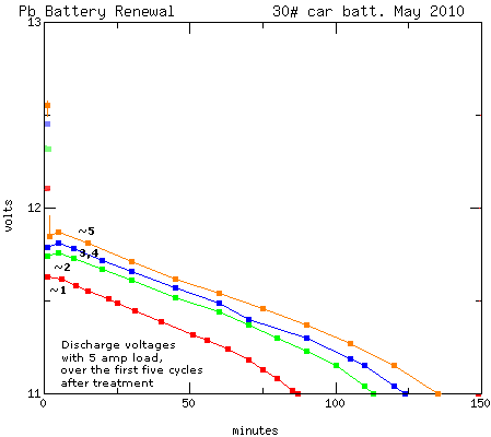
The specific gravity started out at about 1.025. After one charge it
was up to 1.050. After the fifth one it was at 1.08, and it seemed to
be working pretty well. (12 amp-hours is a little more energy than ten
10 amp-hour Ni-MH
"D" cells - and it seems to be about all you can expect from a 30 pound
car
battery. If only those "D" cells would supply enough current to start a
car!) These
figures are way below "normal" - they'll doubtless rise somewhat - but
Gaston Planté used weak acid
(10%) when
he originally invented lead-acid batteries. I'm not sure why such
strong acid is used today.
I then acquired two "worn out" car batteries late in the
month with the new glued-on lids. It is perhaps worth pointing out that
they are not "sealed" - all of them have similar vents to release
gasses. Gluing the lids on can hardly have any other
purpose than to keep sulfate
salts out and prevent them from being given long life. It's certainly
not done for the benefit of the distributors and dealers, who now have
a product with an stale date instead of one they can store empty
indefinitely and fill
when the customer buys it. (One of them is labelled "Delco Freedom" -
as they pull this dirty trick to try to keep us all
under the thumb of their decades long "short life batteries" scam!
Another
lead-acid battery - about the un-greenest battery family there is - is
proudly labelled "Greens" with a picture of an Eagle on it! This sort
of Earthling hypocrisy must surely be studied by students of psychology
on other worlds!)
These lids do pry/break off
with sufficient manipulations of hammer and chisel - but then I
realized one could simply drill 1/2" holes in the "fixed" side of the
top, plug them with rubber (test tube #00) stoppers, and forget about
the "opening" side. Drilling the holes was a cinch - the plastic was
soft and not very thick, and there didn't seem to be anything to hit
underneath blank areas. (Picture below. DO wear face/eye protection
however you open them.)
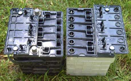
Batteries
with the diabolical new glued-on lids. Note all the extra holes, some
of them square, to make plugging them seem "problematic". The
makers want to make it too much bother to add the sulfate salt so we'll
all buy new batteries every few years instead of having these ones last
the
life of our car.
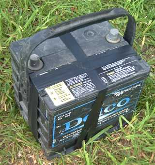
I
considered all the ways I might seal up the holes - wine bottle corks,
rubber test tube stoppers, pieces of plastic with silicone seal - but
in the
end simplicity, electrical tape, the original cover that basically
fits, not filling too full, and the idea of simply keeping the battery
in a fitted plastic battery
box from now on in case of a leak, won out. (I'll add another wrap or
two if it actually loses any fluid.)
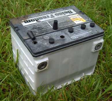
Hey, wow! It's simple to drill
holes just big enough for a small funnel or a hydrometer in the
"solid" side of the lid - lots of empty space under it -
and plug them with firmly
inserted rubber stoppers.
(I made 1/2" holes & used cheap test tube #00 solid stoppers from
"Science Works")
...So, there's no need to do anything to the glued covers!
So! I seem to finally have the battery
restoration process working ...because I finally followed the same
instructions as for alum. I will leave a complete article on the sodium sulfate/Pb battery
renewal web page with all the right instructions, the reasons
behind them, operational theories as far as I understand them, and test
results. And of course the "Sodium Sulfate For Sale" sign!
And I've
just done up a letter paper size poster:
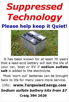
(Not quite accurate - alum (sodium-aluminum sulfate) has been
known that long - who knows about sodium sulfate? At least over 20
years. Will it really last the life of your car? Depends. Too hard to
explain details in a few words. But I like it, anyway!)
http://www.turquoiseenergy.com
Victoria BC


