Turquoise
Energy Ltd. News #29
Victoria BC
Copyright 2010 Craig Carmichael - July 1st 2010
*** Happy Canada Day! ***
http://www.TurquoiseEnergy.com
Contents/Highlights:
June in Brief
(summary)
* This month: Torque converter, solar cells, Ni-Mn
batteries
* Democracy for Canada: On-line referendums
Editorial/Review: Documentary Movie The
Corporation - the pathological pursuit of profit and power
* The dark side of society, the economy and politics
today.
* ...and even with all its fine insights, it doesn't
touch on what
goes on to deliberately keep us using as much oil as possible!
* Attainder looks more and more appealing.
Electric Hubcaptm
("EH") Car Drive System Project
* 3rd party extols the virtues of axial PM (eg, EH) motor format
* Motor fixed. Motor & controller working fine.
* Supermagnets: protect the neodymium... even from
dry air!
* Coffee can jig for getting metal hub past magnets
to assemble rotor
* "Bare-bones" EH motor weight: 37 pounds (17 Kg)
Mechanical or Magnetic Torque
Converter
Project
* The new magnetic radial design.
* Magnets edge-on are much better than face-to-face!
* Swiveling magnets permit one-way force.
* 2" magnet edges (over 30 pounds(?)) are much
better than 1" (15 pounds)
* Arms meet & magnets stick - arm swing limit
stops needed... made.
* Tests reveal all the desired properties except
one... the
force is much too light.
* Installing enough supermagnets to provide enough
torque would seem to be impractical.
* Clock escapements again: this idea, which I keep
harking back to, is probably what'll
work best, but making one that'll take and transfer the forces without
busting...
* Next design figured out: Lots of small nylon
escapement 'anchors' (however many are required!) each with small force
should add up to large force.
* Recap: the several designs since this project
commenced.
Nanocrystalline Solar Cell
Project
* Metal grid rear electrode: no more loss of light
than 'transparent' tin oxide?
* Glaze mix 9 is probably fortuitously close to an
'ideal' clear nanocrystalline borosilicate glaze mix.
* Tartrazine (common yellow food dye) seems like a great dye to use.
Turquoise
Battery Project
* MnO2 discharge with H2O2(?)
* Sealed Ni-Mn test battery
* Measured very low electrode conductivities by
voltmeter (large voltage gradients through electrode thickness during
charge): this, not chemistry,
explains many of the problems I've been having all along.
* Seemingly electrode compaction is insufficient for
good particle contact; even more is required.
* 12 ton hydraulic press purchased for electrode compaction.
The Lead-Acid/Sodium Sulfate Battery
Longevity/Renewal
Project
* Sodium Sulfate
'battery treatment kits' For
Sale
* (Fairly) comprehensive info is now on
the web at:
http://www.TurquoiseEnergy.com/Na2SO4.html
* According to local battery pro, the best way to access batteries with
glued-on lids: drill 1/4" holes in the 'solid' side of the lid, plug
them with heat gun glue. ("Rubber stoppers always leak
sooner or later.")
Newsletters Index/Highlights:
http://www.TurquoiseEnergy.com/TENewslettersIndex.html
Construction Manuals for making your own:
* Electric Hubcap Motor
(latest rev. 2010/02/xx)
- the only 5+ HP motor that can easily be made at home?
* Turquoise Motor Controller (latest rev.
2010/05/31)
- for the Electric Hubcap. (Probably there are commercial
controllers that would work, too.)
* 36 Volt Electric
Fan-Heater
- if you're running your car on electricity, you'll want a
way to defog the windshield and keep warm.
* Lead-acid battery longevity treatment - "worn
out" battery renewal procedure.
all at: http://www.TurquoiseEnergy.com/
June
in Brief
This spring Turquoise Energy Ltd. has received several
thousand dollars from Canada Revenue Agency's Scientific Research
and Experimental Development Tax Credit (SR & ED) program. 35%
of what the clean energy projects have actually cost me in the last two
years has been reimbursed. It's not the kind of salary most experienced
professionals would expect or that I ever received for software
developing or just working as an electronics tech, but it's most
welcome to an independent inventor. Most
major inventions, the ones that really change the world, are "pre
business stage", and no one wants to invest in them or fund them. SR
& ED is also the only government funding program that really seems
to fund the "D" in "R & D" as far as I can discern. And now
being 55 I deferred my homeowner taxes, a major relief. I'm out of
debt, I have money to spend on supplies and tools this year, and I even
got a real TV and have signed onto cable for a while! (As for replacing
the 1984 car...)
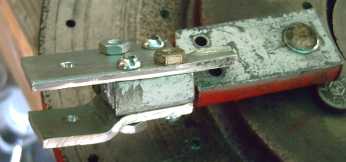
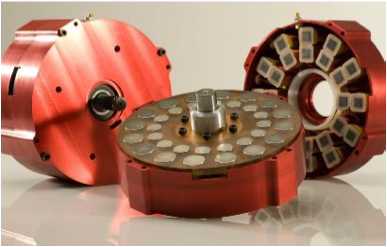
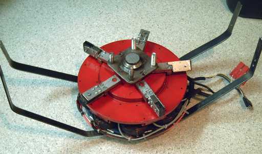 Torque converter side of motor rotor,
with 5 pivoting arms.
The arms match 5 supermagnets on the
inside of the drum driving the
car wheel.
Torque converter side of motor rotor,
with 5 pivoting arms.
The arms match 5 supermagnets on the
inside of the drum driving the
car wheel.
Having again conceived what appeared to be a promising
design, I went to work on the torque converter, with a pause to fix and
test the motor itself after two nickel plated magnets came unglued at
high speed and flew off in May. The rim magnet and even more the
swiveling
drive arm pieces were somewhat intricate, and with
five of everything, consumed many hours in the making and adjusting. By
the 18th, it was ready to test. The test showed it seemed to be doing
all the right things, but the forces created were surprisingly weak. I
decided
that rather than multiply the mass of supermagnets by an amount that
would be hard physically to fit in, it
would be preferable - again - to try something else.
That something else will be something along the lines of
the "anchor" clock escapement mechanism, but using multiple small nylon
"anchors", spaced in 12 divisions around the rim of the rotor. This
time, weak forces will be expected, but they can be multiplied until
they are
strong in total. If 3 or
4 or 6 anchors don't provide enough force (likely), I'll try 9 or 12.
If that's
still insufficient (less likely), there's 18 or 24 in two columns. If
that's still not
enough (hopefully unlikely), I'll make heavier ones. For the motor to
turn vis a vis the drum, all the anchors must swivel back and forth,
rattling in and out of "slots" and "teeth"
in an aluminum ring around
the inner rim of the drum.
As with most or all mechanical torque converters,
the operating principle is that these pieces will swivel effortlessly
at low speed, but put up more and more resistance to changing their
direction of motion as the speed increases, in accordance with the
square of their speed, which is dependent on the speed difference
between motor and wheel.
I managed to put in just a bit of time on the DSSC solar
cell
reflectors, painting underglaze and glaze and firing a few tiles and
melt-quenching
them. Results looked very good in effect, though my ingredient mixing
and technique could be improved to provide a more uniform result. It
may be possible to make a yet
better
nanocrystalline, clear borosilicate glass glaze, but the
characteristics seem great and currently I think beating the "glaze mix
9" I did last month would take considerable doing for
perhaps marginal
improvement. I picked out toluene as a potential electrolyte solvent,
and tartrazine
(yellow food dye) as looking like a good photosensitive dye. Its
maximum absorption centers on 427nm, the blue wavelength of maximum
solar energy.
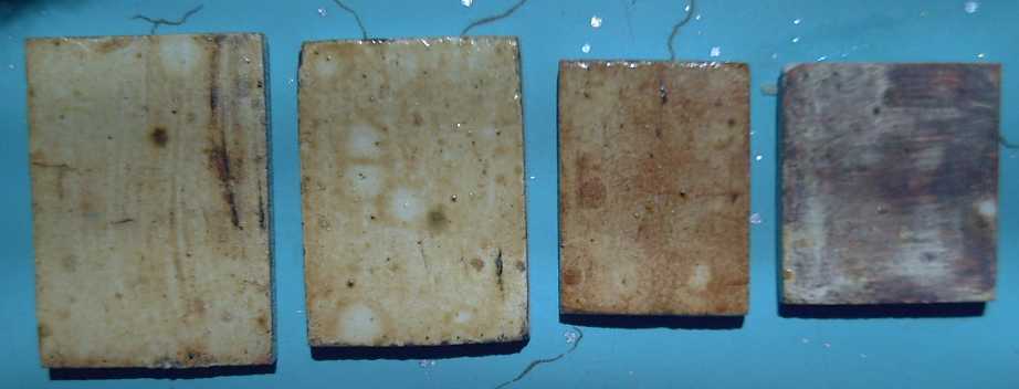
Two tiles with zirconium silicate white underglaze and two thin
layers of glaze, melt quenched both times.
Third one is without underglaze. The glaze has pulled microcrystals out
of the
porcelain near its base.
One (with underglaze) and only one glaze layer, showing many
microcrystals. The leftmost piece looked akin to it before the second
layer was done. Some paintbrush strokes are still visible.
And I spent a few days on
nickel-manganese/salt batteries. I learned a few things and I think
working
batteries of exceptional energy density are close. A better
electrode compactor seemed to be needed, and I spent the last couple of
days of June looking at hydraulic presses, which were much cheaper than
I'd imagined. I bought a used 12 ton one - a common 12 ton hydraulic
jack in a
heavy steel frame - at Barclay's exchange for just $135 (with a couple
of easily replaced loose pieces missing). This would
seem to be the
way to go!
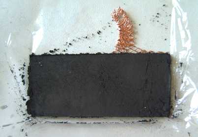
L: Manganese 'negatrode' with copper mesh electron collector after
(apparently insufficient) compaction.
R: Ultimate goal - to give something not so much bigger than the front
case the stuff
to make it roughly the useful energy equivalent of the lead-acid
battery behind.
And I'm thinking: here's July coming, the nicest month to
be down by the sea, and I haven't put together the wave power unit! Ah
well!
I also had another exciting idea in June, unrelated to
clean energy.
Democracy works by participation, but opportunities for the majority to
participate seem to be strictly limited to deciding who to have as your
legislative representative, which choice - "by the way" - will also
determine something else entirely: which partysan politician gets to
inflict his own personal agenda on the whole country or province.
These leaders like to claim that the silent majority "have
given us a mandate" for this, but there is no way to find out what
that silent majority actually wants. It is silent because it has no
voice. Instead, the most vocal and insistent, or the most powerful or
influential, are heard, and their clamouring voices are taken to be
public opinion.
I now plan to
set up a web site where anybody can start a petition about anything -
local, regional, provincial or national, and every applicable Canadian
who cares to can vote on line by ranking the available choices.
(The
choice ranking vote ("The 1, 2 vote", "STV", "automatic runoff") is the
only
single-ballot system where the
voter is completely free to vote exactly as he feels would be
the best outcome, second best, etc, from any number of choices. It wins
hands down over the primitive "X" vote system. The outcome is not
prejudiced by any number of
available choices having any number of variations on the themes -
there's no "vote splitting", and no "strategic voting": no "choosing
the
lesser
of two evils" in hopes of preventing a completely contrary result.)
Although the petitions would be 'unofficial' unless and
until the
system is some day endorsed and taken over by our governing
institutions, anyone who wants to know what the public really thinks
about an issue can simply go to the web site and look it up. It is also
likely that the number of voters will be a good indication of how
strongly people feel on the issue. The more who participate the more
respect the system will gain, and it'll be easy to participate - just
go to
the web site, read and decide. It will be much harder to push an
agenda if it's known that the great majority don't
support it. Those who agitate ceaselessly to get their own way will be
shown to be the small minority they are. When an unwelcome developer
threatens
to sue a city if it doesn't do as he
wishes, city council will have much more power to stand up to him if
they can say "Sorry, the citizens have rejected your proposal."
Conversely, it may be found that things they are reluctant to endorse
may be shown to be quite acceptable to the public.
There will be a lot involved in setting this up, and I
won't get it going this
year if I start it on my own. Then there will be a lot of publicity
needed so that people know
about it and how to use it. There are also serious issues of cheating
(ability to wrongly cast multiple votes) versus having a vast
collection of data on people so their voting eligibility status is
known, and maintaining the security of that data.
But I trust I won't be acting alone on this once people
start to grasp the tremendous potential of having such a system in
place.
Editorial/Review: The
Corporation
Documentary
I watched a documentary
video, The Corporation - the pathological pursuit of profit and
power. (Mongrel DVD. It looks from an insert like it's also a
Penguin book, by author Joel Bakan.) I
watched it in a few short
sittings: it was too much to absorb, and much of it was too disturbing,
to take in all at once. I think
it's a "must see" if you
want insight into the real workings of the economy and politics - into
a good part of
why things are the way they are and perhaps why we're gradually losing
our freedoms, inching for
many decades towards being police states. First
the various ways in which the actions of corporations accurately mimic
the
behavioral
profile of psychopaths are discussed, one at a time. Then there are
various specific subject areas and cases, some really shocking.
Did you
know that as well as being "Rah, rah!" for Mussolini and Hitler, big
business almost turned the USA into a fascist state in 1935? They
didn't like Roosevelt's "New Deal". Think of the world we'd live in
today if they had been successful! The rather surprising betrayal of
the plan to congress by the ruthless general they picked to be dictator
derailed execution the planned coup, for which half a million
soldiers or disgruntled veterans had been earmarked.
Things long considered to be basic human rights such as
drinking water
and saving crop seed have been privatized at the behest of
corporations to be sold for profit to the people that should already
own them. But even the psychologically
fine-tuned persuasions
of advertising to get children to nag parents to buy things they won't
want (not to mention adult targeting) don't escape the documentary's
purveyance.
Our society benefits greatly from trade and industry, but
the dark
side of the way it's run today is horrific. A corporation is a "person"
in the eyes of the law, yet it never grows old and dies, and if it
kills, steals, bribes, kidnaps or destroys the environment, the worst
it faces is a fine - a calculated business expense. So it rolls on and
on, an invincible, unaccountable, psychopathic juggernaut.
My one note is that for all its revelations, the video
doesn't seem to recognize what now seems plain to me: that big oil, the
automakers, and the battery companies are all owned not by random
profiteering stock market swingers, but by one group: a clique of
ruthless gangsters who work deliberately and unceasingly for a century
to kill all
alternatives to gasoline. They are rotting our society from the inside.
Identifying
the problems is the first step. Determining
good solutions is harder. The Russians revolted against the Czar only
to find they had raised a new and worse form of dictatorship,
Bolshevism.
What are good solutions to the many unaccountable, rogue
corporations and their owners who so control and manipulate our
economies and dominate our policies and politics, gradually destroying
the planet and working so much harm to human freedom, safety and
security? Near the end of the film, some cases
and solutions are discussed.
It turns out
government has indeed reserved to itself the power to dissolve
corporations - it just never
does it, regardless of the current provocation or the company's history
of continuing lawlessness or harm. And in California, even regardless
of a
citizens' group formed to demand that one particular state oil company
be
dissolved. The attorney general wouldn't do
it. There seem to be too many politicans who've gained power by
representing big business interests rather than the real national
interest.
People have taken legal action, sometimes successfully,
against the
most
flagrant abuses, and in one case shown it came down to actual
revolution and
bloodshed -
but it's all in the film.
The idea of attainder has grown on me. Why should it only
be people working for progress - inventors like Rudolf Diesel
(murdered for his engine), Churchill, Roosevelt, the three Kennedy
brothers - that
have to look over their shoulders, hit the dirt when a car backfires,
and wonder when their life might
suddenly be violently snuffed out? Why not also the most successful
criminals as well, who often perpetrate such violence, and who are so
rich and powerful that they seem to be above ordinary law? It would
seem
that only such a direct act by the peoples' chosen representatives can
terminate their ever growing domination of society and commerce, and
return their vast stashes of well-laundered but essentially ill-gotten
gains over to the public treasury.
Perhaps fittingly, though the film features many American
corporate insiders and critics (including corporation presidents and a
surprisingly humble Michael Moore), the end credits show it's a
Canadian production with
public financing from a number of Canada's leading sources.
The Electric HubcapTM
Vehicle Drive System
Commendation of EH type motors
Here's a commendation of the Electric Hubcap (EH) type of
motor from a company (Apex Drive Labs) making one of rather similar
configuration. I downloaded this a year or two ago and just ran across
it again. Two points of interest are first that their gap from coils to
magnets is, like on the EH, unusually wide - about 1/2 inch, and second
that
they use two stators to drive one rotor, providing almost two motors in
one thicker package.
The
coils of this motor are "U" shaped, with the two ends
meeting
an
inner and an outer magnet on the central rotor.
(Unfortunately,
no motor weight was given, so there's no
basis
for power to weight ratio comparison with the EH.)
Most radial flux motors have hundredths of an inch flux
gap. The .5 inch gap (which any "regular" motor person would think
must be a typo) means the useless static pull from the magnets to the
stator is far less for the axial flux type, which leads to lower
bearing
wear, no gradual loss of magnetism in the supermagnets, and higher
efficiency.
I suspect the efficiency improves especially in larger
power sizes - I've heard it said that around 10 HP up the PM motor
becomes less
efficient than the induction motor. Inefficiency in the larger sizes
must surely stem from the tremendous static forces between the magnets
and the stator -- in radial flux designs. It seems likely Apex derived
the wide flux gap from mathematical modeling. I got there by
experiments that showed it worked best, without at the time knowing
others were using a similar gap.
Apex's having two stators - one set of coils on each side
of the rotor - helps to compensate for the low magnetic flux of
electromagnets compared to supermagnets. It might almost be said to
be two motors in one. At the time of the article, they planned two
direct drive
motors, on left
and right wheels, for a small Neighborhood Electric Vehicle (NEV).
Evidently by the watt specs they have almost four times the power of
the EH, so almost 8
times the power with two motors - 40 HP. This is far more power than is
required for a NEV, but without a torque converter or gears the
huge size would be needed to attain sufficient torque to get the car
going up
a hill.
"It is widely recognized that axial
flux permanent magnet (AFPM) machines usually have higher torque
densities and efficiencies than their radial flux (RFPM) counterparts.
Its pancake shape geometry and high torque capability make AFPM motors
a preferred choice for direct-drive systems. In recent years, many
different topologies of AFPM machines have been developed and reported
[1]."
My comments on this: Yes, higher torque, but for direct
drive of the wheels, it's still not commensurate with what's needed
except with very oversize motors. Hence
gears, or better, an efficient torque converter, allows a much smaller
motor. (Since there's no ultra-high permeability soft magnetic
materials or superconducting coils to raise the electromagnet flux and
hence the torque.) Yes, there can be "many different" axial flux
topologies, but
I'll bet the Electric Hubcap is by far the easiest one to make, having
standard auto and trailer axle parts for its main structure and common
boxed strip nails for coil cores! The parts
are all readily available (...no "by prescription only" or otherwise
banned or controlled items) and any motor repair shop could easily
make them.
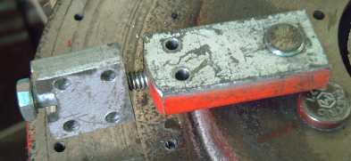
Repairs to Magnet Rotor
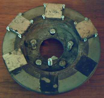
The rotor, motor side: - new flat head screws help to "clip in"
the magnets so none fly off again.
Note also how solidly the lug bolts for the torque converter arms are
pounded in: at least one of the heads is visibly flattened and dented.
One of the four lug bolts for the axle hub had to be removed to fit all
five for the torque converter.
Drilling holes in a magnet worked, but was difficult, and
each hole broke out a clump as the drill neared the bottom. I
turned the magnet over and used the divots as
the recesses for the flat head machine screws. (This was the magnet
that the nickel plating came off of.)
I soon spray painted this assembly
well with rust paint to prevent corrosion of the rotor and the magnet
iron and the vulnerable
neodymium. Someone tipped me off that the neodymium degrades
from oxygen even in dry air, turning into non-magnetic oxide powder, so
I
spray painted all my supermagnets, which are mostly scratched
up from use on various rotors one time or other. (So that's why the
older ones always seem to look worse and to be weaker than I remember!)
I glued the magnet on, then drilled and threaded the holes
in the
rotor. The threading tap broke off in the last hole - impossible to do
anything with, so I put one screw on the outside of the magnet.
It's also worth noting that I use a big tin can with the
ends removed (and a slit cut in the edge so it'll fit in) when I put
the axle hub on or take it off. (I've been doing this for some time but
have previously neglected to mention it.) Otherwise, the hub always
ends up latching itself onto a magnet with considerable force, making
the job very difficult and rather hazardous. Even at that, the hub has
to be worked into place onto the lug bolts. (The tin can, though it's
also attracted, is thin metal and much easier to manipulate around the
magnets.)
Motor Weight
I worked out the weight of the bare EH motor if it was
made now with
the rather light 6129 disk brake rotor disks, which seem (without
having tried them yet) as close to ideal as will be found using
ready-made parts. It would weigh about 37-1/2 pounds, 17 Kg. (Parts
cost
might be around $300 to $350. "Bare motor" means: no mounting
straps, no cover, no torque converter specific pieces... except two
trailer hubs and the 6" flanged trailer axle... it
would only need one hub and perhaps a short axle if made for use
without a torque converter.)
Axle (6" long, 1-1/16" diam, with flange) - 1.6 (all weights in Kg)
4 bearings, axle nut - .37
2 hubs (length turned down to both fit on axle, diameter turned down to
fit in 6129 rotors) - 2.6 (est)
2 6129 Disk Brake Disks @ 3.0 - 6.0
9 coils @ .46 - 4.14
12 magnets @ .125 - 1.5
4 lug bolts for rotor - .15
other nuts and bolts - .14
Wires, plugs, Hall sensors - .5
Total 17 Kg, 37.5 pounds
This weight means little to the car overall. And with the
link
pins,
it will pivot when the car wheel hits a bump so it's largely not
"unsprung weight". Still... lighter is
better.
Potential places where weight could be further reduced:
* Replace the stator hub and its brake rotor disk with a single flat
steel disk, with a short pipe coupling welded to its center to mount
the
bearings. That might save about 1.25 Kg (2-3/4 pounds).
* Replace the 1-1/16" axle with 1". This would save only a bit, and
since the flange is needed on the end, it seems impractical to replace
the trailer axle with a 6" long, 1" diameter bolt.
* Drill holes in the rotor disks and cut out some unneeded metal in the
spaces between coils. The holes would also act as ventilation holes,
but otherwise, I'm guessing it would be a fair bit of work for minimal
reduction. (You don't want the rotor metal much thinner, and be careful
where you cut - the metal completes magnetic circuits between
coils/magnets.)
* IF nanocrystalline ceramic cores can be produced, they would be
lighter than metal by around 3.5 pounds. This is the biggest potential
reduction: 9% - IF.
If there's going to be a torque converter, replacing the
magnet rotor assembly - disk and hub - might make it harder to
build with
only a marginal weight reduction, so I haven't mentioned that idea. On
the
other hand, the trailer hub has to be turned down on a lathe anyway.
Mechanical or Magnetic Torque
Converter Project:
Torque Leverage Without Gears
When I first screwed magnets into the aluminum drum, I
didn't concern myself with north-south polarity. Either polarity would
attract the steel
arms, right? Then I realized that the steel arms as the rotor spun
would be magnetizing themselves first in one direction, then the other,
and it takes energy for that to happen - a needless inefficiency! When
I remounted them on the outside, I set them all the same way.
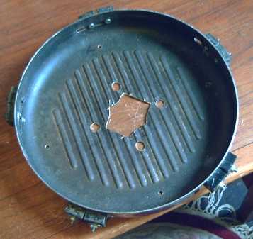
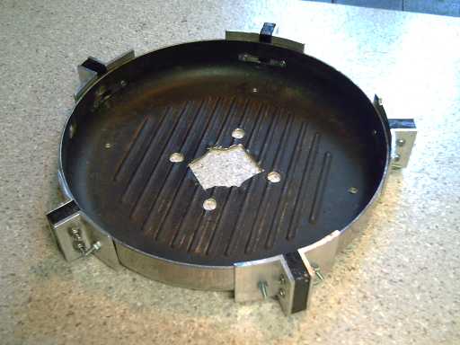
First I mounted the magnets on the inside of the rim.
Then I realized that the 12" aluminum pan was practically non-magnetic,
and that an extra 1/2 inch of radius could be gained by putting them on
the outside.
It's now about as big as the 13" car wheel allows -
any larger and a flat tire would cause damage, with the magnets hitting
the
road.
On the evening of the 4th I finished making the new
pivoting arms to match the diameter of the large aluminum drum. I did
them by bolting new pieces onto the original (2nd set) arms. Two piece
arms were necessary anyway because they were
now longer (2 & 9/16" from pivot point to tip) than the distance
between adjacent pivot bolts, so full length straight arms couldn't
have been
threaded on.
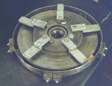
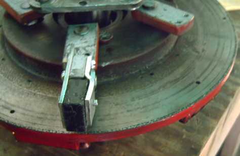
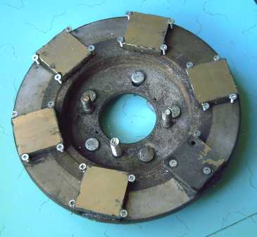
Motor rotor/torque converter input rotor with pivoting torque
converter arms June 4th,
"upside down" in torque converter output drum.
The arrangement has a side
effect: the inner end of the
outer arm pieces hits the center hub edge and limits the amount of
swing of
the arm (2 or 3" from one side to the other - can be increased by
grinding the inner end of the piece). Whether this is detrimental,
valuable or neutral remains to be determined.
With the limited pivoting, the arms won't swing back far
enough to fit in the blocks intended to hold them back until the center
of the next magnet is reached. I'll try without them first. The arms
are longer now and with more inertia should take longer to swing out,
which could solve the problem 'automatically'.
On the 5th I mounted the rotor and the drum on the axle
and tried turning the rotor, holding the drum steady with a stick. The
arms were about the right length, and the the force impulses to the
drum seemed to be pretty much unidirectional, but they seemed much too
light to move a car. As before, the greatest impulses were with the
rotor going a very low speed. The rotor was easily turned; obviously
the motor could take a lot more without being in danger of being
stalled - this would be a benefit of the increased outer diameter.
I could easily double or even triple the amount of steel
attracted to the magnets, but I suspected that would still be
insufficient. The way to get a much greater field and force would be to
put supermagnets on the ends of the arms and have supermagnets
attracting supermagnets.
This brings the design back to being similar to one of my
early ones (that I didn't finish putting together owing to lack of
confidence in it) with a sliding aluminum "flat donut" plate that could
pivot back and forth about 2-1/2" (from which the five slots in the
drum rim remain), but with three key differences:
1. the mechanical foundation - pivoting arms, is both simpler and
more robust than the sliding plate. It should be much less subject to
heat and to wearing out.
2. there are no axial forces acting on the magnets: the arms pull
towards the rim rather than to one side.
3. The hinge of the pivot pins is only about 2/5 of the way out
to the drum, giving the motor a leverage that allows it to start
turning more easily in the presence of heavy magnetic cogging forces.
The amount of the leverage depends on a number of factors and can't
simply be ascribed as being 5:2.
On the 6th, an idea about something someone said some
months ago, which had been in the back of my mind, came forward. He
said something along the lines of "It's really hard to pull magnets
straight apart, but they can be slid apart sideways much more easily.
Your design is sliding them apart; it needs to be pulling them apart to
get the main force."
I decided if I was going to put magnets on the arms,
perhaps they should be edge-on instead of face-on to the drum rim
magnets. Turning the magnetic lines of force would have a modified
effect. Experimenting with a 1"x1"x.5" magnet held with pliers seemed
promising, then I thought, what if the drum magnets were also edge on?
I put another 1x1x.5 magnet in the side of a vice and put them both
edge on.
Sure enough! There was a slight repulsive force as the
magnets approached each other from the left or right, then a very
powerful attractive force once they were in line. They could easily be
slid apart up and down, but to the left or right was very difficult:
although they were "sliding past" each other, it was closer to the
level of force of "pulling apart" rather than "sliding apart".
Note: Using a piece of unmagnetized steel with
the magnet edge on showed very low levels of force. If a magnet is to
act on
steel, a pole facing the steel is better. Forces between two edge-on
magnets seemed to be a magnitude greater than any configuration of
magnet on steel, so magnet to magnet was the obvious choice.
I expected that this force could be multiplied to any
desired extent by stacking magnets. If I stacked two rim magnets to get
a 1"x1"x1" cube, oriented edge facing in, it should almost double it.
Even better would be magnets that were magnetized "sideways" compared
with the usual. With a similar double magnet on the arm a huge force
would be needed to pull them past each other.
Instead when I ran the experiment it didn't feel any
stronger with the doubled magnets - perhaps not even as strong. To
verify this I got a fish scale (no fish were harmed) and measured the
amount of force needed. With single magnets, it took 12 pounds of force
to slide them apart with a .08" sheet aluminum spacer between them
(similar
to the minimum gap they might actually have installed), and 16 pounds
with the
magnets touching. With double magnets making cubes it took only 9 and
12 pounds! It
seems the "sharp edge" of magnetism was the vital factor. Obviously,
with 2" tall magnets instead of 1" and with the same .5" edge, the
force should be around double, but there wasn't enough height for them.
(1.5" might fit, but I'd have to buy them that size - the heat from
cutting the magnets - at least with the zip disk in the angle grinder,
which seems the practical way - loses so much magnetism that the 1.5"
would be little or no better than 1".) Later I realized that while a 2"
magnet wouldn't fit inside on the arms, the ones on the outside could
overhang a bit. I tested a 1" against a 2" in the vice and found the
forces were about 15 and 20 pounds, a modest but worthwhile increase.
Also noted in passing in the experiment was that unless
the magnets were sticking well out from the vice and the pliers, the
tools' steel shorted out much of the magnetic field.
Later (10th) I tried a 1x2x.5" magnet with the 1" edge
against the 2" edge. If the space could be found this was a modest
improvement, giving about 17-18 pounds with the spacer. Finally (11th)
I tried the obvious optimum: two 2x1x.5" magnets with their 2" faces
together. The force, with spacer, went off the end of the 25 pound fish
scale, probably 30-35 pounds. Here is the obvious
configuration if there's room. With such forces, one might even be able
to use fairly wide air gaps for loose fitting tolerances. That would
make them easiest to make. For me at this point, it would also mean
switching to a new motor rotor (ironically one with a taller center hub
is ideal, to accommodate the magnet lengths) and a new torque converter
drum - a lot of rebuilding.
I can visualize the 'optimum' embodiment of the design
more easily than I
can take apart and re-assemble everything (and more easily than I can
find the ideal drum): an ideal 12" diameter drum of aluminum with 2.1"
straight rim walls (no curve to the base), .5 x 1" steel arms with 3/8"
pivot bolts, .5 x 1 x 2" outer arms, sideways, next to the magnets
outside of them, and 1/8" stainless steel plates to attach the magnets
to these.
The present question is: do I have to build the optimum to
get the car
moving properly, or is the design with lighter parts and lesser
magnetisms that I can throw together fairly easily now good enough? Or,
the other nagging question, is it possible that even the optimum isn't
good enough?
If the arms swung freely, the slight repulsive force would
hold back a slow moving arm until its inner end was past center. But as
the motor sped up, the centrifugal force flinging the arms outwards
would overcome the weak magnetism and put the magnets directly across
from each other hopefully just after the pin passed the center point,
so the force should mainly or all be one way and should increase with
motor speed.
I found there was actually a considerable backwards force
as the magnets latched onto each other: the arms jumping forward
pulled the drum backwards. It occurred to me that if
the arm magnet was able to twist sideways, or to move inwards away from
the drum rim magnet, the arm perhaps wouldn't have to pivot, and the
arm magnet would simply twist or retract as it entered the zone of
light repulsion approaching the rim magnet, then straighten or spring
forward again as it entered the strong attraction zone, to give the
drum rim the sharp tug that should turn the wheel.
The one "sticking point" would be if the motor came to
rest with all the magnets lined up, would it have the force to break
loose and start spinning? The swinging arms get around the problem,
giving the motor a lot of leverage to pull the magnets apart.
Well, there's still a lot of "hopefullys" in here and it's
shy on descriptive math weighing the balance of the forces. But
formulae characterize the various parameters of a given design, and a
given
design is exactly what we didn't have yet.
On the 7th, I mounted a 1x2x.5" magnet edge-on outside of
the drum rim, held by aluminum angle pieces, having of course removed
the flat
mounted magnets. The setup at this point allowed experimentation by
hand turning the rotors on the axle along with easy removal of the drum
with no other disassembly. Ideas could now be tested at a far greater
rate than was possible at any earlier time with any other design.
Approaching the (vertical)
drum magnet with a magnet held
horizontal disclosed that the forces attracting them were virtually
annulled. (In fact, twisting the loose 'arm' magnet horizontal proved
to be the easy way to separate the two supermagnets.) However, when
they were lined up, there was a very strong force wishing to twist the
arm magnet back to vertical orientation. The forces on the approach and
exit tended to want to spin it the other way up.
If the arm magnet could be mounted "hinged" so it could
twist 90º, from horizontal to vertical with one face (eg, north)
up or to the right only, it would turn horizontal on the approach to
the drum magnet - from either direction - then would suddenly go
vertical just about as the magnets passed each other. Thus there would
be little or no "backwards" force on the approach but the most powerful
forward tug just as they passed. The tug comes from the sudden slowing
of the outer end of the five arms, which kinetic energy is imparted to
the rim via the magnets. The faster the motor is spinning, the greater
the velocity or the arms and the greater the centrifugal forces holding
them straight out, and the greater the impetus as they pass the rim
magnets - provided the magnetic forces are sufficient.
(It would seem necessary to stop the twist a few degrees
short of vertical to ensure that it twists back, since at exactly
vertical, it would equally want to flip both ways and might stay
upright.)
When I tested the finished assembly on the car wheel, the
forces seemed to be all in the right direction, there was no vibration,
and the turning force increased with motor RPM. Unfortunately, that
turning force was much too light by at least an order of magnitude - I
could rather easily stop the jacked-up car wheel by hand.
If it had seemed like even 1/4 as much force as needed, I'd have
started working out ways to add enough arms and magnets to make it
work. But to add ten times as many supermagnets or get them ten times
bigger seems problematic. At some point, it's easier to just do a
greatly overpowered motor with ten times the needed horsepower in order
to get the needed torque without gears. But then it wouldn't fit on the
outside of a car wheel, so the main purpose is defeated.
What's Next?
The best idea now looks like the clock escapement type
of mechanism. The hard part is to figure out one that looks robust
enough to transfer the torque forces from the motor rotor to the slower
wheel rotor without the serious vibrations of the shifting plate
design, and without quickly falling apart.
I now have the glimmerings of a design that might
work.
It's going to take at least another month to put it together.
The idea is little "many" short two-point nylon "clock
escapement anchors"
sized so that at
least a dozen will fit around the outside of the motor rotor, with the
points sticking into slots (rectangular holes) in a strip (aluminum?)
around the inside of the rim of the drum. Each one will provide only a
small force (like all my other designs have done so far anyway), but
they'll all add up. (Ack! It has to be made so it
can be assembled without dismounting the anchors! The slots will have
to be open to the open edge so motor and drum can be fitted together.
But I digress.)
The pivot holes for the anchors will be drilled through
the
motor rotor between magnets, and threaded. (Tentatively, 1/4" bolts for
axles.) 2, 3, 4, 6, 8, 9, 10 or 12 anchors can be installed with
balanced forces, as seems appropriate when the forces are measured. I
can start with just two, or even one, and check the results without
making the whole works, in case changes are needed to the design.
(...why do I have the feeling it'll need more like 24, 36 or 48, and
how will I fit them all? At least 24 and possibly 36 could be doable by
stacking them
two or three per axle, if the slots in the rim are wide enough.)
These anchors will swivel back and forth very fast. Since
E = .5 M V^2, faster gives more energy than heavier. But I
can add steel weights to nylon anchors too, if it looks like
that'll help, or make them of steel entirely.
In principle I think I'll also keep the magnets
mechanism in
some similar form, with the external drum magnets, as a means to
lock up the converter to 1 to 1 when the torque required is light.
RECAP
Perhaps it would be interesting to run through the several
designs of torque converter since the start of the project a over year
ago.
My first idea was that one could use a typical induction
motor design adapted to axial flux, but instead of electric coils
creating a rotating magnetic field, have supermagnets on the motor
rotor. That way, the output rotor would be driven by a supermagnet
strength rotating field. The fundamental problem with that was that the
motor itself was still driven by electromagnets, and the unit still
couldn't have more torque than they would provide. The motor wouldn't
run fast enough to provide any more torque than without the new
mechanism. And all the slip was
just losses: there was no way to convert or transform
the torque, only to couple the original, insufficient torque to
the output.
The second idea seemed good in principle: magnets would
flip up and down on hinges. They'd flip down next to a magnet on the
output rotor just as it was going by, giving it a tug forward without a
preceding tug backwards. The third design was a variation on the same
theme. A plate on the output rotor holding all its magnets was to slide
backwards an inch or more as the motor rotor magnets reached them, move
forward to the end stops, and then the inertia and the attraction
between magnets would give the output rotor a 'hit' of torque as the
motor moved on. There were two main problems: the first was that if the
magnets lined up with the motor stopped, the motor probably wouldn't be
able to break free and start spinning. The second was that the
mechanical construction didn't seem up to the level of the forces
involved. I built some of the parts of these two designs and tried
turning them by hand, then gave up
without completing them.
A couple of times I studied clock escapement mechanisms.
They seemed to have the basic idea: when you try to run it too fast, it
gets very hard to push. If you turned it around, running the motor fast
should create a lot of torque. But it looked like the 'escapement'
pieces would be getting bashed around at very high speed and would
probably break or wear out quickly. But perhaps something that had
those beveled hits, with a higher mass and hence lower speed...
The fourth design was purely mechanical: a plate would
spin with the motor, and would hit ramps on the output rotor at
intervals that would cause it to shift sideways, in and out. The hits
on the ramps would be 'torque hits' to the car wheel. I went through
about 3 variations but found they all had serious vibration and not
enough turning force, or that the turning forces were so short the tire
absorbed them. In retrospect, the main cause of the vibration was that
since
it wasn't one solidly fixed assembly, it was actually much easier for
the whole motor to bounce in and out than for it to cause the car
to move - so it did.
In between a couple of these variations, I thought (again)
about Constantinesco's 1920's designs, and looked up some more recent
patents as well. The big trouble was that his design took linear space
between the driving motor and the driven output. Then I thought, what
if the motor was mounted on the car body above the wheel? It all
started to look quite straightforward when I found a ratchet wrench
that was strong enough to move the car without a problem. (I put it on
the car wheel and stepped on it - the car rolled.) But early in
construction, I suddenly realized that since the car and wheel moved
separately at bumps, the torque applying rod would simply make the car
bounce up and down instead of turning the wheel. I was also having
serious doubts about the efficiency of forcing a heavy wrench and steel
bar to shift back and forth at high speeds.
So I finished the last version of the shifting plate and
tried it out. The vibration was still terrible, for the reason given.
Somehow, I had to shift the axis of action from axial to transverse
with a workable design. Transverse forces would be in the wheel turning
plane, and furthermore a number of them spaced around the rim would
cancel out their vibrations.
The first idea for this was swinging arms on the motor
that almost hooked, sort of clung, to pins around the inside of the rim
of an output drum, yanking them along before they let go. It might have
worked, but I didn't get it made.
On April 30th I doodled out a diagram of a
mechanism with the same swinging arms but with magnets on them, going
past more magnets inside the rim of the output rotor drum. I figured
the arms would freely swing forward magnetically when they reached the
magnets, then un-freely pull away from them. Then I also figured that
since
only attracting forces were involved, the arm magnets could simply be
replaced by steel. But when briefly tested (in May) the forces seemed
too light, and also somewhat 'balanced', pulling both directions: as
the arms swung forward magnetically, they also pulled the drum
backwards.
The unique feature was that the motor would pry the arms
and rim magnets away from each other with leverage, so the motor would
need far less torque to start up with the magnets 'latched' in the
attracting position, the frustrating problem of all the other magnetic
designs.
To get more radius of action and more prying leverage, I
went back to the larger 12" (aluminum frying pan) drum of the earlier
magnetic trials, and then to putting the magnets on the outside of the
non-magnetic rim. This had the benefit of allowing me to see what the
arms were doing and run more experiments faster.
Finally some experiments disclosed that two magnets
edge-on to each other have much more 'ideal' characteristics for the
job, especially if they could pivot as well as the arms swing. This led
to this month's design, which had the right rotational forces, but they
were much lighter than I expected, and the amount of supermagnet mass
needed to up them sufficiently would seem impractical.
Now I'm thinking again about clock escapements. This time,
with the forces radial and balancing, and as many small "anchors"
or whatever as possible or as needed, spaced all around the outer rim,
to transfer motor
forces to wheel, increasingly with motor speed.
Nanocrystalline Ceramic Motor Coil
Cores Project
I seem to be out of inspiration for this at the moment. (I
may try using FeO again, this time well mashed with the mortar and
pestle, or maybe steel grindings. Finding fine metal powders or lower
oxides instead of fully oxidized metal oxide powders might be of
considerable assistance. and costly.)
Ultra-high permeability soft magnetic materials may or may
not exist, and may or may not be found if they do, but good "FINEMET"
nanocrystalline alloy cores are made, and good results have been
obtained with composite materials. This much (my original goal) is
known to be possible.
Nanocrystalline Reflective Rear Electrode for Dye
Sensitized Solar Cells
Some Design Considerations - Rationale for using certain materials
I chose tartrazine (yellow food dye from the
grocery store) as a good looking photosensitive organic dye. Its
wavelength of
maximum absorption, 427 nanometers, is at about the wavelength of the
strongest levels of solar irradiation (below, the peak of the yellow
area, also the peak of the red on some charts, is at around 400nm).
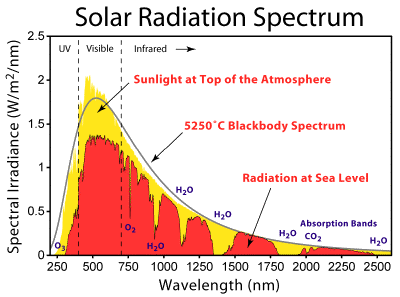
Totally off topic,
this particular chart was especially interesting to me as it notes the
absorption of specific wavelengths by ozone, oxygen, CO2 and water
vapor in the
atmosphere. That's interesting in itself, but also I thought from
previous limited information I'd found that the 'cyclic' absorption
lines on Titan from
methane vapor were quite unlike from the spectrum of water vapor. This
graph reveals instead a
similar sort of spectral pattern.
Titan is an atmospheric planet, between Mercury
and Mars in size, that orbits Saturn. It's the only other world in the
solar system with an air pressure similar to Earth's, and composed
mainly of the same gas, nitrogen. It is also the only other world with
land and rivers, lakes and seas - albeit of liquid methane.
I see from a release June 4th, along with an earlier title
announcing a lecture about it at a conference, that space scientists
are finally starting to talk about the possibility there's life on
Titan
-- not because of the aquatic leaves and stems ("rocks"!?!?) in the
Huygens lander images and evidenced in the Cassini T14 RSS pass, and
not because of the forests of gigantic trees visually revealed and
otherwise evidenced by the Cassini SAR radar (Cassini SAR image swaths
of Titan's temperate and polar regions are similar in nature only to
satellite/Google Earth images of forested areas.) Instead they're
saying it for the equally evident chemical/spectral reasons: covering
over of expected inorganics such as water ice by complex and unknown
organic spectra with abundant benzene, and a seemingly unexpected
absorption of
expected energetic gasses (in particular H2 and HC2H, acetylene) at the
surface. (The shortage of hydrogen at the surface seems to be what's
finally caused the awakening, perhaps because it fit with a prior
theory that hypothetical Titan life might use it for energy as a
breathing gas.) So far
they are still looking for "microbes" on a world evidently verdant with
huge
forests and aquatic vegetation of a scale unknown on Earth.
On January 15th, 2005, the Huygens probe parachuted down
and as far as I can tell splatted down on Titan's swampy tropical tidal
methane seas right on top of a dune, just a couple of inches below sea
level. The images obtained were immediately released to the public on
the Huygens DISR website, in a form which was said (most
unprofessionally) to be the original raw images: but which were
actually grotesquely contrast magnified, and by completely inconsistent
amounts. Luckily, René Pascal pointed me to two archives of the
actual raw images. It took me until mid July in uncounted hours of
study to figure out the true nature of the scenes: submerged wetlands
(formed into dunes by Titan's powerful tides), covered in aquatic
vegetation of stupendous dimensions. After that everything started to
fit into place. Apparently scientists haven't got that far yet. Perhaps
they were misled by their own unmentioned and bizarre image processing.
My studies of Titan from 2005 to 2007 are on the web in my
'book', Living Titan.
Some later thoughts (mainly 2008) on a number of worlds and the strange
things and activities on them are at Space
Update Notes Web Page. The main index to my pages on that site is: www.saers.com/~craig .
But I seriously digress!
The choice of borosilicate glass ("pyrex") for the glaze
layer and for the front glass is because it is the most transparent
glass at the strongest wavelengths. In fact its transparency is
exceeded
only by pure silica - quartz, which can't readily be purchased nor made
in a typical kiln.
"Pyrex glass
(borosilicate type) is opaque to radiation in the UV-B band and
attains a maximum transmission level at 340 nm and beyond (Acra et
al. 1984). The coefficient of transparency for borosilicate glass, 1.0
cm in thickness, is 0.08 at 310 nm, rises sharply to 0.65 at 330 nm,
and attains a peak level of 0.95-0.99 from 360 to 500 nm. (Weast
1972)"
Although I purchased a piece of
borosilicate ("wood stove door") glass to divide into solar cell test
pieces, and stannous chloride and tin dioxide, having now tried to put
the conductive tin oxide layer on some test pieces I must conclude that
unless its horribly expensive I'd be better off to order some ready
made.
(Oh, wait, I forgot... it's become almost impossible to find goods on
the web any more, with all the "parasite sites" that each appear a
dozen times in the same search and claim they link to
thousands of companies selling just what you want, dominating the
results of any search for anything and knocking out the bona-fide
sellers. Maybe local glass companies might know something...) The
resistances I've heard of for commercially made pieces are ohms or tens
of ohms, whereas the best I've got - on porcelain which process I can't
duplicate on glass or glaze - is hundreds of ohms, with thousands and a
cloudy appearance being my best on glass.
Perhaps I can do better on glaze at high temperature, but
it would mean a lot of manipulating glowing hot ceramics straight out
of
the kiln, and then putting them back in. It will certainly complicate
the melt-quench. Unless I can think of a better technique than what I'm
envisioning now.
As an alternative, perhaps it would be easier to use an
"open" metal grill that lets most of the light pass by as the rear
electrode collector, and forget about making the glaze conductive. Of
course, its thickness would greatly thicken the electrolyte layer, even
with quite fine mesh.
The 'glaze mix 9' seems, by some fluke of luck given that
up to about mix 6 it was supposed to be for another purpose entirely,
to be pretty much ideal for the reflective rear reflectors, or
certainly 'close enough' for working purposes.
I painted on a thin white zircon (zirconium silicate)
underglaze and then a very thin glaze layer on two pieces of porcelain,
and one with no zircon for comparison, and fired and quenched them. One
with zircon was clearer than the other two, but all had colour, and
showed clumps of coloured microcrystals under strong magnification. I
painted on a second thin glaze layer and
fired and quenched again. This time, the glaze looked uniform and clear
except for a couple of streaks on one piece, the microcrystals
evidently having given way to transparently thin nanocrystals in both
layers.
With thick underglazes (or two layers), the glaze wouldn't
stick on the porcelain, and with thick glazes, there were a lot of
dark, coloured microcrystals rather than transparent nanocrystals. It
would seem that two or more thin layers is the way to go rather than
trying to do everything with one coat of glaze.
The zircon white underglaze seems a little brighter than
the titania (titanium oxide) white underglaze - at least to my eyes.
(Must try tin oxide, too! ...would that be called "tinia"? Of the three
common glaze whiteners, Ti and Zr are adjacent in the same column of
the periodic table.) In the comparison piece with no underglaze, the
whole tone was less bright, and the glaze seemed 'rougher' at the
microlevel, especially with only one layer. I expect the glaze was
pulling 'impurities' out of the grainy porcelain, and conforming to its
grain, instead of having fine white zircon smoothing its base.
The reason for the titanium oxide nanocrystals in the
glaze is because it has a very high refractive index (highest of any
substance) and a very high dispersion - the prismatic separation of
colours. It is likely to most modify and disperse the light to give
good
prospects of making it more susceptible to being absorbed by the dye on
the way back out.
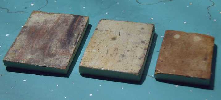 Zircon underglaze and one thin coat of glaze (no underglaze on
rightmost piece).
Zircon underglaze and one thin coat of glaze (no underglaze on
rightmost piece).
The melt-quenched glazes were clouded with microcrystals.
After a second thin coat of glaze, fired and melt-quenched, the
microcrytals were evidently
refined down to transparent nanocrystals except in the piece with no
underglaze. A new piece with only one glaze layer was fired and
quenched in the same batch.
I'd like to try expanding on the glaze layers idea a bit
by
painting 'tinia' on the last glaze layer, and then doing another layer
of tinia on top of that. At some point, it should become conductive.
(though it may lose transparency - all in trying it out and seeing if
some way works.)
An alternative configuration for the solar cells, if
making the glaze conductive works, and IF the electrolyte is quite
transparent, might be to have the nanocrystalline titania sintered onto
the rear electrode instead of the front one. The rear electrode would
then be the negative and the electrolyte ions would flow the other way
around.
Now if that titania could be formed into vertical
nanotubes or nanorods impregnated with the dye, that "light guide"
could possibly be
still another improvement.
Turquoise Battery Project
June Experiments
When the new version
torque converter didn't seem to have enough 'kick' on the 23rd, I
decided it was high time to get back to the battery project, sitting
since April in promising condition. Perhaps the best thing to do next
was to make a sealed Ni-Mn/KCl battery that wouldn't need watering all
the time, and wondering what other things might be getting in or
escaping though the open top.
This time I considered thoughts that had come to me about
the manganese while I was making the previous electrodes in April.
For manganese, I had purchased MnO2 (local pottery supply)
and Mn metal powder (Micron Metals). The
form in which these are added to the battery probably deserves
consideration, since starting with one electrode charged and the other
discharged is bad. It seemed easy to add some of each to get the
desired starting charge state, but each form has its own small issue:
The MnO2 (Mn valence IV) seems to be the common 'pottery
glaze' form of manganese, but if put into a battery it makes a
pre-charged 'positrode' (MnO2 being the usual positive chemical of
non-rechargeable dry cells). For a negative, it's 'overdischarged'.
Expected discharged form in salt solution would be Mn(OH)2 (II) or MnO
(II). Starting from a higher 'overdischarged' oxide, less conductive
and probably bulkier, seems counterproductive. One solution is to add a
higher percentage of metallic Mn. But MnO2 is a cheap oxide and Mn
powder (typical of pure metal powders) is expensive. To reduce the
valence of the Mn oxide from four to two (or even to three) would be
quite helpful by itself, and would reduce the metallic Mn required.
NiOOH (III) can be discharged to Ni(OH)2 (II) with
hydrogen peroxide, H2O2. Oddly enough, this oxidizer seems in effect to
steal even more oxygen, probably from the water in the presence of the
nickel compound, which bubbles off as (presumably) O2.
The first experiment was to see if it would do the same
for MnO2. It did seem to work the same way. (The gas didn't
smell, so
it wasn't H2, and that's pretty much the only other choice besides O2.)
A week later, I realized the bubbling had stopped because the hydrogen
peroxide was exhausted, not because the MnO2 was all converted. I added
some more H2O2 and it went back to frothing away. I converted all my
MnO2.
I bought some
more to weigh the product before
and after next time. I should be able to tell by the weight change if
it's MnO, MnOOH, or
Mn(OH)2... and also make sure it's not actually oxidizing to some even
higher valence form!
The pure metal, Mn (0), is the negatively charged form in
the battery. Yet I started to think: when the Mn powder was mixed with
liquid, it might well discharge spontaneously before the hydrogen
overvoltage ingredients were added. It all looks pretty black - I can't
really tell MnO2 from Mn powder in the damp mix, let alone discern
MnO or Mn(OH)2. If it was discharging, I wouldn't know.
The obvious thing to do here is to mix the hydrogen
overvoltage and all other dry ingredients first, then add the Mn
powder last.
Another consideration that may have been a factor in the
difficult charging of the previous Ni/Mn mix is that I don't have (and
can't seem to get) nickel powder. I added the nickel as discharged
Ni(OH)2 (II) as well. Now that I think about it, this presumably has to
charge up to Ni (0) before the manganese can start to charge, since
it's a lower voltage.
So perhaps I should be using monel powder instead? (It's
around 2/3 Ni & 1/3 Cu).
I looked at both of them at 40x magnification. The
"blackish" monel looks like shiny little rounded chunks of silvery
metal - which of course it is. The nickel hydroxide looks like green
laundry soap
flakes. While the fluffy Ni(OH)2 'snowflakes' tend to be of similar
size to monel grains, some are much smaller, and when compacted they'll
break down much finer.
It seems to take some doing to charge the Ni(OH)2 to Ni
metal one-time, whereas the monel is already "charged". Depending how
intimately the Ni needs to be in contact with the Mn to effectively
raise the hydrogen overvoltage (or whatever it does that seems to
help), the fine Ni(OH)2 may do a much better job. The best way to find
out
is probably to try them both, and to try a mix with half of each. (At
the rate I've been running battery experiments, that could take months!)
If the compaction is good, the electrode should certainly
be highly conductive with all the monel or nickel, and the manganese
metal and lower oxide being quite conductive as well. If the "+" can be
made half as good, a pretty small battery might start a car engine.
Another thought is to buy NiO at the pottery supply if
monel powder proves too coarse. Why run down my Ni(OH)2 supply when
it's what's needed for the positive electrodes and is harder to get?
While I was at it, I took a magnified look at MnO2 and Mn
powder.
The metal chunks in the "grayish" powder had a bronzy sheen and were
much more irregular than the monel particles. The particle size was
similar (well, I did order them both as -320 mesh! Perhaps I should be
ordering micron sizes.)
The MnO2, quite black at any scale, was clumped into quite
large particles, but these easily broke down with compaction. They
didn't seem to get as fine as the Ni(OH)2.
When some was dry, I inspected the Mn(OH)2 (or is it
MnO?). (That's the trouble with pouring 3% H2O2 into some powder... it
got soaked into a wet slurry. Oh well, pretty much dried overnight when
spread around a bit. But I doubt I added enough H2O2 to
reduce all the MnO2 powder. I really should calculate it out and
then measure the ingredients - that would be easier if I knew exactly
what the reduction reaction was.)
I decided to use a previous nickel "+" electrode that was
already in the battery test case. (A slightly dangerous thing to do
since it hasn't proved itself and I don't remember exactly what's in it
- but easiest.) The final mixture for the first "-" was:
Expanded copper mesh collector sheet/backing, approx. 1.3" x 3" - 1.75g
Monel alloy powder - 10g (conductivity, ??)
Mn(OH)2 (?) - 7g (active ingredient - discharged state)
Mn metal powder - 5g (active ingredient - charged state)
Sb4O6 - .2g (increases hydrogen overvoltage)
CMC gum - .2g (glue)
Albumin (egg white) - a smear (significantly increases hydrogen
overvoltage even in PPM quantities)
HOH distilled - 2cc
In the electrolyte is Na2B4O7:10H2O (borax) and KCl
(potassium chloride), not to mention
water.
The KCl is of course the neutral pH salt electrolyte. The
idea of the borax is that if hydrogen is created by overcharging the
negatrode, instead of making H2 gas, it'll change it to a borohydride,
which, being like the borax, soluble, will diffuse over to the positive
electrode to give up its 'H's and discharge some NiOOH to Ni(OH)2. This
will create heat but eliminate buildup of hydrogen gas pressure.
On the first attempt to charge the battery, the voltage
went up to only ~~ 1.6 volts while charging and rapidly dropped off to
under a volt with the charge removed. The pressure went up to 12 PSI in
a few hours without the battery being charged. Overnight I reduced the
charge. In the morning the voltage was only marginally higher, but the
pressure was up to 18 PSI.
I unscrewed the pressure gauge and sniffed the air coming
out as I did. I didn't smell much, and it didn't seem to be hydrogen.
That seemed to say the negative wasn't bubbling hydrogen gas. So I
concluded that the positive electrode was already charged and giving
off oxygen on further charge, thus the negative wasn't reacting with it
to charge properly.
I took the battery apart and put the positrode in 3% H2O2.
There were lots of tiny bubbles for over two hours, and even after
four, a little shake would start it mildly fizzing again. This
evidently means it was charged to NiOOH and was now being discharged to
Ni(OH)2. After that I put it in water to rinse it out.
As I left it in a considerable puddle of H2O2 and the
bubbling continued for such a long time (even at that I can't say it
had really ended), I think my previous attempts to discharge nickel
positrodes used much too little H2O2 for much too short a period of
time to discharge them more than a fraction of their full charge. This
may well account for a few disappointing experiment results.
(FWIW The reaction might be: 4 NiOOH [III] + 4 H2O2 => 4 NiOHOH [II]
+ 2 H2O + 3 O2.)
On further testing the cell, the positive connection
(nickel-brass)
corroded away, and in the restoration I put the meter probe at various
points in the electrode briquette itself. This disclosed that while
charging there was a great voltage gradient through the thickness of
both electrodes. The closer the probe to the interface between the
electrodes, the
greater the voltage drop from the collector screen. Evidently both
electrodes have very high internal resistances.
This could explain many poor experiment results!
And I've started to realize that if a battery has 10 AH of material and
it'll only charge at (eg) 20 mA, it'll take over 500 hours to charge
it! A few hours, or even days, may not bring it up to the expected
voltage, explaining that many "failures" weren't due to the
electrochemistry at all. When the area of best conductivity to the
collector becomes fully charged, the voltage goes up to some ridiculous
level, and I finally conclude it isn't working right at all. But much
of the rest of the electrode has yet to be charged, so as soon as the
charge is removed, the voltage drops below the expected voltage. And if
the current that can be stuffed into the poorly conductive battery
isn't above the level of self discharge, it'll never get charged.
Perhaps my electrode compactor, though forming the powders
into a seemingly solid 'briquette', isn't pressing hard enough? My
briquettes crumble more easily than the ones from the Ni-Cd dry cell,
though none are immune to losing material when mechanically stressed.
It would seem I probably need to find a still better compacting
technique. Maybe double the screws? -- screws going in from both sides
of the compactor to
increase the available pressure? Maybe pound the compactor with a big
hammer when it's already fully tightened, and then see if the bolts
will turn in a bit farther?
I decided on the 29th to
look into hydraulic presses. A big 45 ton press is
$2000, but a 6 ton one is just $100, and a 12 ton press is $270:
nothing
like the high capital costs I'd expected. I even got a used 12-ton at
Barclay's Exchange for $150. (KMS Tools had just sold their last 6 ton
one: I saw
it - it waved at me on its way out the door. But I'm guessing that 6
tons would be a bit underpowered anyway.) And I had found doing up a
bunch
of
bolts to compact an electrode would have been a serious production
bottleneck even for enough homemade batteries for a car. The press is
just a common 12
ton hydraulic jack in a big heavy steel frame.
BTW I wish I had some much finer copper mesh. I got a
coarse mesh roll at an art store (Opus) and I was probably lucky to
find that. It doesn't help conductivity when much of the active
material is somewhat distant from the collector. Also BTW this was the
first time I had the mortar and pestle to give the mixture a good
grinding and mixing before compacting it.
Higher Voltage, Cheaper, Higher Energy Density Batteries: the easy
way?
In considering making higher voltage batteries with
multiple cells, I had thought of putting a "+" and a "-" electrode on
opposite sides of one collector sheet, when I was using nickel-brass
brass
collector sheets. Then when I started using metal grilles, it occurred
to me one could more simply use a
metal grill wrapped around a thin piece of hard plastic.
Now I'm thinking: why even use the plastic? The voltage of
both electrodes is necessarily the same, so why does the electrolyte
need to be blocked, especially if it's a dry cell with no extraneous
liquid that might bypass the electrodes? Why not just compact the two
electrodes together into one bipolar briquette? And then, with all the
current
simply flowing across the thickness, why use any grill or collector
sheet at
all? Why not have nothing but the active electrode briquettes?
This would be the simplest and cheapest, with the highest possible
energy density.
Here we hark back to Volta's original 1798 "electric
pile" in a modern form. Except for a collector grille or plate in each
end electrode, the whole
battery is full of nothing but active electrodes, with the requisite
separators
between them.
It's getting tempting to try making a "full size" 12 volt
Ni-Mn battery
with 6 cells of 3" x 6" electrodes, maybe 50 or more amp-hours. But I'd
better work on improving the conductivity first - it would be
of little use for transport if it only supplies (eg) a half amp for 100
hours instead
of 50 amps for 45 minutes.
A Battery Comparisons Thought
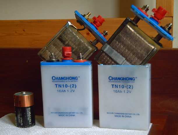 * Left: "D" cell size battery. (Ni-MH
"D" cells are up to 10 AH, 1.2 V,
"1000
charges", 100 WH/Kg.)
* Left: "D" cell size battery. (Ni-MH
"D" cells are up to 10 AH, 1.2 V,
"1000
charges", 100 WH/Kg.)
* Center, Right: Ni-Fe 10 AH, 1.2 V
pocket cell battery, 20 WH/Kg.
(Larger ones are said to be up to 50 WH/Kg.)
These last for decades. The active chemicals are inside rectangular
"pockets"
which are combined into flat plates. Changhong uses battery production
line equipment purchased from Varta in Sweden, so their batteries are
about the same as Varta's.
* The "hacked" electrodes at the
back-left was a Ni-Ni experiment in
the spring.
* I imagine the same batteries as
Ni-Mn and think: 2V cells and
almost double the energy, for all types!
Knowing a few more details
now about batteries, I have an observation for comparing various
chemistries with a
little more savvy, especially alkaline types versus lead-acid. The most
important
ratings for EV batteries are
WH/Kg and WH/$.
Lead-acid battery ratings are deceptively high. They're
rated at a 20 hour discharge rate, and the amp-hours are much reduced
at high rates. And even with
sodium sulfate keeping them from decaying, they can only be discharged
to about 60% depth of discharge for electric drive because the
voltage seems to start seriously dropping off when much current is
asked
for
beyond around 50%. With Ni-Cd or Ni-MH, one can tap around 90%
of the
charge out before the voltage plummets, and the amp-hour ratings are
for a shorter discharge time and they degrade less at high rates.
Therefore,
most other batteries
store perhaps 60% more usable energy than a lead-acid battery
with
the
same rating. A 100 AH lead-acid battery should therefore be compared
with a 60-65 AH battery of most other types. The same derating scale
could be used in reverse for the cost, ie, multiply the lead-acid cost
by 1.6 to compare it to other chemistries. And the weight, already
heavy, must also be multiplied by 1.6 to compare it fairly with other
types.
Thus if I can make a 60 AH 12 V Ni-Mn battery (a rough
estimate, perhaps a little on the high side) by incorporating
everything I've found) in a 4" x
4"
x 8" case (128 cubic inches) it would compare with a 100 AH size 27
deep cycle lead-acid battery of 12" x 7" x 8" size (672 in^3)
- five times the size.
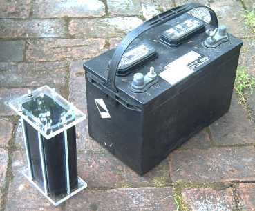
The Ultimate?
for the front battery
to be usable energy equivalent to the rear one,
cheap, safe, and superior in every
other way.
Lead-Acid/Sodium
Sulfate Battery
Renewal
Project
Sodium
Sulfate for Battery Renewal (Click for Prices, Info.)
I finished restoring the batteries I got last month and a
couple of others. There was tremendous variation in initial performance
after draining the acid and adding water and sodium sulfate, one
battery seeming to be pretty fair after one or two charges. Two others
maintained only 8 volts at 10 amps for just a minute or so on the first
try, but one rapidly improved. The other seemed to get just marginally
better each cycle, slightly perking up in voltage and time, but never
really seeming to work properly.
Shorting out Shorts?
I tried for a while to burn out "shorts"(?) in some cells
by shorting the battery out with a light jumper cable (often the
battery still read a volt or two while "shorted"), or giving them a
very heavy load - with the caps loosened or removed. Some of them
didn't respond. One was loaded with car headlights, 50 or 60 amps,
which started flickering and suddenly went brighter, then again blinked
brighter still. Voltmeter readings jumped up as well. I thought, "Aha!
That's done it!" but then it flickered some more and went dimmer again.
It went brighter and darker several times, but ended up not fixed. That
was the best I attained.
I could hear the water boiling in the battery, presumably
where the current was heating the shorts up. There was a strong smell
of hydrogen gas
after a while and I moved the operation outdoors.
There are two main problems: first is that the liquid
cools the short, making it much harder to burn out than if it was in
air. Second, charging the battery seems to strengthen and build up the
short. But in order to try to burn the short out with a heavy load or
short circuit, the battery must be charged. It's working against itself.
With one battery, I dumped out the liquid then refilled
all the cells except the problem one. Then I charged it for a bit, then
shorted it. The theory here is that with little or no liquid in the
cell, the only path for current is through the short, and the short is
no longer protected from heat by being submerged.
After a minute or two, the voltage suddenly dropped from
about 1.5 to 0.5 volts and stayed there. (I "shorted" it through a thin
jumper cable, not a total short.) Then I refilled the battery and tried
to charge it. It charges up to 12+ volts, but gradually drops again. I
think there's still some little shorting connection left over that
discharges a cell.
The battery was pretty flat when I started. Perhaps
I should have charged it longer before shorting it, so it would have
supplied more current to burn out the whatever it is. I'm going to use
the battery a while and see if it clears up by itself.
I won't say curing battery shorts can't be done, but my
success has been pretty limited
so far, and for considerable trouble. Better I should concentrate on
getting the Ni-Mn batteries working!
http://www.TurquoiseEnergy.com
Victoria BC