Turquoise
Energy Ltd. News #30
Victoria BC
Copyright 2010 Craig Carmichael - August 3rd 2010
http://www.TurquoiseEnergy.com
Contents/Highlights:
July in Brief
(summary)
* Torque Converter - "type 5: clock escapement"
* Battery tab spot welder
* Working Ni-Mn
chemistry!
Battery chemie promises highest energy
densities,
"green", indefinite life, maintenance free, low cost.
Chevy Volt: I'm suspicious
* Delays, luxury car price, no TV ads... and specs
show abysmal
efficiency: HALF the miles/KWH of the EV-1.
* "Who Killed the Electric Car" is to be repeated with MiEV.
* It's all part of a century old pattern.
* Epilogue: A "typical example" of electric car suppression?
Mechanical or Magnetic Torque
Converter
Project
* "Crown" of
twisted sprockets
* Escapement "anchors"
* Principle seems to work
* Punch for making improved twisted sprockets; then a new one
for bigger ones.
Simple Capacitive Discharge/Resistance Spot
Welder Project
* Battery electrodes use spot welding for secure connections
* Electrodes: heavy Cu wires sanded to cone-shaped ends
* Trial 1: 10,000uF charged to 15 volts makes feeble welds on
thin battery jumpers
* Trial 2: 112,800uF @ 15 volts makes a bigger spark
* With short, heavy leed wires it zaps holes, pits
* With practice & technique, welds thin
battery tabs to battery.
* Shortest project yet, under 4 hours!
* Improved Model July 22nd
Turquoise
Battery Project
* Short Summary
* New Nickel-Manganese Battery
Chemistry Works! - for the first time ever, 2 volt alkaline
cells!
* Higher EV/PHEV battery energy densities are now possible, eg
140 WH/Kg and up!
* Made: Large 3" x 6" flat plate Ni-Mn Battery
* Depressing press news: bolt-down electrode
compactor is stronger than 12 ton hydraulic press
* Too much pressure; lots of bubbling: changed from
sealed dry cells to flooded, vented cells
* It's alkaline, even with salt electrolyte. pH read
12-13.
* Copper structural materials don't work in the positrodes -
rapidly corrode away. Trying nickel-brass plates.
* Copper negatrodes seem great!
* VERY gradually starting to hold charge - the voltages are
going up and lasting longer as the weeks pass.
* Stacking electrodes for higher voltage cells: ...dip in paint
or wax or something to seal edges?
* New, more powerful electrode compactor; bigger electrodes?
* Side thought: why are there no high energy density nickel-iron
batteries, eg, 70-80 WH/Kg?
* Exciting new Ni-Fe research - from India - is also applicable
to Ni-Mn. (next two items)
* Better electrode binder?
* Catalytic H2 + O2 => H2O gas recombiner reduces gas
pressures: allows maintenance-free sealed cells after all!
Newsletters Index/Highlights:
http://www.TurquoiseEnergy.com/TENewslettersIndex.html
Construction Manuals for making your own:
* Electric Hubcap Motor
(latest rev. 2010/02/xx)
- the only 5+ HP motor that can easily be made at home?
* Turquoise Motor Controller (latest rev.
2010/05/31)
- for the Electric Hubcap. (Probably there are commercial
controllers that would work, too.)
* 36 Volt Electric
Fan-Heater
- if you're running your car on electricity, you'll want a
way to defog the windshield and keep warm.
* Lead-acid battery longevity treatment - "worn
out" battery renewal procedure.
* Simple Spot Welder for battery tabs, connections (in This newsletter)
all at: http://www.TurquoiseEnergy.com/
July
in Brief
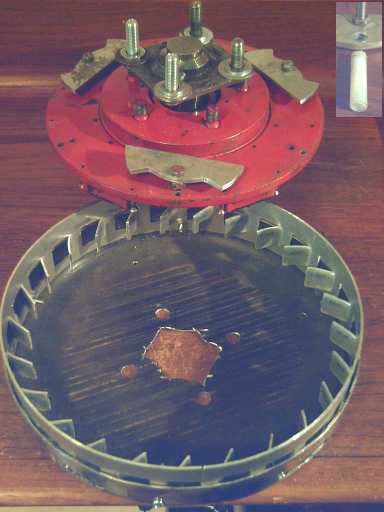 Latest Torque Converter:
- Motor rotor/axle with escapements (top),
- converter drum (bottom),
- Nylon escapement bushings "pipe" (inset)
As I finally had the basic design details in my head,
everything looked good for trying out an 'escapement' torque converter
idea. A trial strip of aluminum with sprocket teeth was made.
Three escapement
anchors were made, a plastic 'template' and then two 'real' ones of
aluminum, and each one's shape was better refined. When I started, I
had only a meager
idea of what a 'right' or 'wrong' shape might be. I drilled and tapped
6
holes around the rim of the motor rotor for their pivot axles.
A hand turning test showed it seemed to do what it was
supposed to.
At low speed, the motor rotor and the converter drum turned freely
against each other, but by around just 30 RPM, the escapements buzzed
back
and forth, rather noisily, and the force on the stationary rotor was up
to around 2
foot-pounds, with two of six anchors installed.
Some time was lavished on making a punch
and die to stamp out 25 larger sprocket teeth around the rim of a new
sprocket strip. And I realized the drum could be made with from the
strip and a circle of flat aluminum plate, instead of finding a frying
pan
of exactly the right size and shape. This would be helpful to all
future builders, assuming the design worked. Then I finally set to
figuring out the best size and shape for the escapements and making
them.
After several hours of grinding, sanding, filing and
burnishing I got three that didn't jam and tried it out. Performance
was dismal! Heavier and more pieces, within reason, wouldn't be enough
to get it to move
the car.
Another vague plan is forming in my head, this one for
using the same sprocket gear and similar arrangement, but driving
the
escapements back and forth, which would directly turn the gear and
wheel, rather than relying on oscillating masses.
 Capacitive Discharge Resistance Spot Welder
On the 15th I phoned around for a spot welder for battery
plates and leeds. There seemed to be none for sale in town.
For some comic relief I decided to see what
went into one. A little
investigation on the internet disclosed it's done in essence by
suddenly discharging capacitors, using a foot switch to trigger the
discharge. Electrodes were just heavy copper wire. Dispensing with all
formalities, I ended up being able
to weld thin battery tabs with a small power adapter feeding 0.11
farads - two dozen 4700uF, 25 volt capacitors
from
Queale Electronics (their largest size), which I later upped to 32:
0.15 F. These went via fat wires straight to the electrodes, which
arced as soon as the contacts were made. I found out other welders use
from 1 to 4.5 farads, but these operate through an SCR switch that
limits the current. Without the switch my 'underpowered' unit seemed to
be 'good enough'.
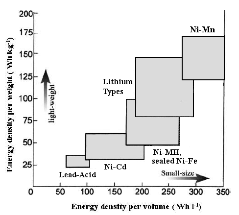 Battery Energy Densities Comparison Chart,
showing the promise of
Ni-Mn catalytic dry cells
with stacked bipolar electrodes.
(...vertical is about right, but it should be way past the right hand
edge of the graph!)
I decided the Ni-Mn battery chemistry looked sound enough
to warrant making a "full size" cell with the 3" x 6" electrodes.
Loosely filling the compactor with 'Ni' mix and compacting it resulted
in
a 20 AH positrode about 4mm thick. A matching 25 AH negatrode was made,
which turned out to be under 2mm, total 6mm per pair. This cell seemed
at first to be a
failure, and the copper framework of the positrode quickly corroded
itself out
of existance. I changed it from a
sealed dry cell to a flooded wet cell and replaced the copper mesh with
a nickel-brass plate. Gradually it started to
charge to higher voltages and drop off more slowly - over a
period of weeks. I almost gave up a couple of times. In spite of using
neutral salt electrolyte the cell
became quite alkaline (explaining the copper corrosion), about pH 12 or
13, but not 14 according to my
pH test strips.
Now after finding a bit more info I think I may
'form'/charge the
electrodes in a flooded tank at higher currents than I've been
able to use in a confined cell enclosure, but then use them in sealed
dry
cells. Manganese is element #25, beside iron #26, and as far as I can
tell, Ni-Mn cells should last as long as Ni-Fe - perhaps a virtually
unlimited
cycle life as sealed dry cells according to the latest Ni-Fe battery
research -
2004,
from India. The
voltage, about 1.9 "nominal" volt cells instead of 1.2 is the big
difference. The
Indian
research found a catalytic device to combine H2 and O2 gasses created
during charging into water, reducing pressure and making sealed Ni-Fe
cells possible for the first time. (I have what I hope is a better,
simpler, cheaper catalyst - antimony, which is mixed into the electrode
material.)
The Indian research also gave a figure for electrode
compaction pressure, something I've been seeking for 2-1/2 years: 4-1/2
tons per square inch for their iron electrodes. My compactor of 1/4"
steel plate bulges noticably
in the middle when the bolts are done up, and I finally bought 1/2"
plate steel to make a new compactor, which will have closely spaced
bolts to exert greater pressure. It should be at least in the ballpark.
I can judge by electrical resistance readings on the positrode, which
are rather high with the present compactor. The "bolt-down compactor
box" is a
key tool for "DIY" battery making without a costly factory.
Chevy Volt: I'm suspicious
What's with the Chevy Volt? Here's a chunk of my opinion:
It's no surprise to me that it
seems to be taking its time getting to market, or that the price is too
high.
The
electric range is abysmal considering its very considerable lithium
battery
pack. In fact, the pack is 16 KWH, said to give an electric
driving range of "up to" 40 miles. (Why then pricey lithium? - you can
get that sort of range with cheap lead-acid batteries.)
The EV-1 on the other hand had a 21
KWH Ni-MH battery pack that gave a range of 100 miles. This
says the EV-1, though it weighed almost 3000 pounds, got about 100/21 =
4.75 miles per
KWH. (This approximates other published figures.) The Volt works out to
"up to" 40/16 = 2.5 miles per KWH - HALF the fuel
economy of the EV-1!
So it uses twice as much electricity from the grid as the EV-1 (or most
anything else) to
recharge. This means it needs a very large lithium battery pack,
driving the retail price way up, to go its very modest distance on
electricity.
What is the problem? It would seem the power train and the
motor itself
must be awfully inefficient. It's a huge induction motor - 110 HP, the
equivalent of at least a 265 HP gasoline engine.
That sort of size should be more suitable for a large truck. Compare
that with a typical 10-30 HP EV motor... and with the 5.5 HP Electric
Hubcap (which admittedly has yet to prove its practicality). And
lithium batteries are inherently not
the best technology for
electric vehicles, though some good workarounds seem to have been
developed... that add even more to the cost. Notwithstanding what's
being said, I'll bet that the Volt's
lithiums will only last a few years (about the same as lead-acid
properly treated with
sodium sulfate), whereas it
looked like the Ni-MH batteries in the EV-1 "would outlive the cars".
The whole effort looks shoddy, even pathetic -- from
the world's biggest automaker, who nevertheless was in deep financial
trouble until bailed out by the public purse on the promise they'd make
electric transportation.
The same shareholders control the nickel-metal hydride
EV battery
company, Chevron-Cobasys (formerly inventor Ovshinsky's Ovonics,
then GM-Ovonics) that made the batteries that made the EV-1 et
al so successful over a decade ago. But since 2001 it
never
makes, sells, further develops, nor (via numerous acquired patents)
permits to exist, any Ni-MH EV
batteries. Of course they won't
restart production and put them in the Volt. That's the last thing
they
want! Electric cars having been forced upon them by a disturbed public,
they've managed to pretend the proven best batteries, cheaper than
lithiums, are no good, and
devolve the whole publicly funded program to this one long delayed
model and rumors of
another
to come from Ford. Where are the
PHEV vans, trucks and suvs? Why are the great, economical batteries
left to rot
--
and where is even basic good engineering?
I believe they want the Volt to be the only, the worst and
the highest priced piece of trash they can make it, as long delayed as
they can hold it back, without attracting a
lynch mob and without having president Obama seek elsewhere for a
solution.
Then, if it ever goes on sale, they'll "phase it out" as soon as they
can get away with it
"because there's no demand."
I also read in the papers ('fraid this is from memory from
a month or two ago) that the Mitsubishi MiEV
electric car "is coming"... but that the few coming to the west (or was
it only to Australia?) this
year will
only be leased, not sold, and that then they will all be recalled and
sent
back to Japan. It sounded like the same thing as in "Who Killed the
Electric Car",
happening all over again - brazenly announced in advance!
They're supposed to be available in late 2011, but I suspect
there
will somehow be further obstacles to
buying one next year. (BTW, the MiEV gets 80 miles from the very same
size
battery pack, 16 KWH, that takes the Volt "up to" 40 miles.)
At the same time, we are shamelessly deluged with TV ads
for
all types of gasoline vehicles, or at best occasionally for non plug-in
hybrids. Seen any of those glowing TV ads for the Volt or any other EV
or plug-in hybrid?
These people, who around 1900 seized control of our
fledgling transportation economy, are not on the same side as the rest
of us.
This enemy within is now fighting desperately to keep electric vehicles
out of the public's hands and by this repetitious TV and other
propaganda to try
to make us
forget there ever was such a thing. The appearance of electric cars or
plug-in hybrids for sale to the public at economic prices would be a
death blow to their giant oil oligopoly, and they'll fight to the death
to prevent it. They shut down, undermine and
suppress
electric car and EV battery development and commercial enterprises as
they make their appearance, and
let the public
conclude from
seeing nothing ever actually available for sale that they must not
really be economically
feasible.
They have waged this war successfully decade after decade. How long
will we
continue to let
them dictate to us that we shall burn fossil fuel, with wanton
inefficiency, for all our transport needs?
Hah! That was going to be the end of my tirade, but here's a great
epilogue:
a typical example.
Someone has sent me a link to Evergreen
Electric Vehicles - with a promising looking electric car "about to
be
introduced" at the 2008 Seattle Auto Show. This "medium speed vehicle"
(up to 60 Km/H) must have been the product of much fine development
work, and there are videos of it driving around, beautifully. Whether
or not it ever made
it to the show, it would seem it caught the attention of the enemy: the
web
site was last updated in 2008. It's full of great reports and
good news that, as always, abruptly ends with no explanation.
If president Obama had given any portion of a billion
dollars to this Washington company (and provided it and its key
personnel with protection against corporate, financial and physical
violence), these cars could well be in production, on the roads, and
probably in high demand with a big waiting list by now.
Their web site: www.evergreenelectromotive.com/
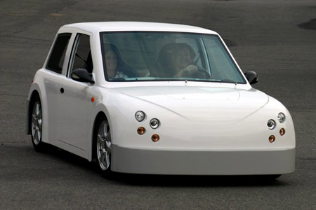
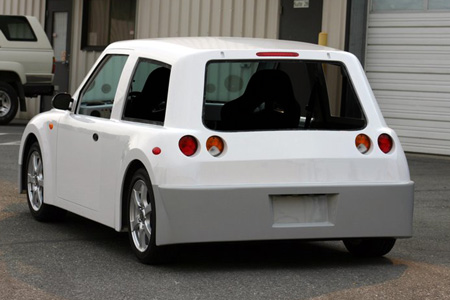 The Evergreen 2008 EHC
When people see one individual
company, idea or person disappear, it's puzzling, but the
obvious conclusion is that something individual happened to it - its
business
plan was poor, financing didn't come through, the product was
uneconomic or bad circumstances forced it out of business, or perhaps
the head of the company had some sort of personal or family trouble or
an accident. But various such
companies, some with "corpse" web sites, can be found -- and where are
the successful ones, electrifying our transport system? For example,
try looking up companies doing
nickel-zinc batteries. There were two or three when I looked a while
back, also a flat-plate Ni-MH battery company, all with nothing recent
on their sites and no explanations. The ones I tried don't answer
e-mails. Why would all these various people go to all the work of
developing products, creating companies and web sites, and then just
vanish on the eve of commercial production?
And what happened to the people who invented engines that
run on compressed air a couple of years ago - two independent designs
in
two separate countries? And the big, safe plastic compressed air tank
whose side would just rip open and release the air if it was hit or
punctured? "Now we don't need to burn fossil fuel to drive cars any
more." they said on TV. But where are the cars running on air? What
happened to the
entire promising technology? The engines worked. Everything was going
great -
until they hit the TV news. The first news was also the last.
And whatever became of all those electric car companies
that started in the 1970's with the US "oil crisis"? Popular Mechanics
magazine et al were raving about them and detailing their features, but
I don't know of a single
electric car having actually been sold in that era. I met a person who
invested in one of them after an electric car ride, saying "This is the
future!" and he said "Nothing happened. It just never went anywhere."
He was certain there had been interference.
History has recorded the "disappearance" (read murder) of
Diesel from a ferry, the burning (read arson) of Edison's Ni-Fe battery
factory and the
nefarious dealings of GM with Constantinesco to ensure his fuel saving
mechanical torque converter was never used, but it would sure be nice
to know what happens
to all these
other disappeared companies, and to the inventors and product
developers that
created them! I bet one could
look back and find the decades are littered with sabotaged attempts to
introduce
non-petroleum transportation and better electric car batteries, each
naive startup wondering why no one else had already done it.
We can eat all the best
food we want, and try different diets,
develop new multi-vitamins, be nature-friendly or whatever, but it's
hard to make
transportation healthy unless people start to realize there seems to be
a huge tapeworm within, clothed with money and power but somehow
swallowing everything good and... according to what I've heard...
spitting out the evidence in mid ocean from tankers, in
45 gallon
oil drums filled with cement.
Mechanical or Magnetic Torque
Converter Project:
The Quest for Torque Leverage Without Gears
Last month's magnetic design seemed to do all the right
things... but with so little force it seemed impractical to try to up
it to car moving magnitude. So I went back to the clock escapement
idea, and I had a
design in my head by the end of June. I sketched out a modified design
July eighth, then made a modified version of what I'd sketched.
For the rim of the output drum, I ended up cutting 37
slots between 37 solid "sprockets", each element 1/2" wide. I cut slits
in from the edge, and simply bent out the pieces for the slots. I
elected not to do this to the rim of the drum itself, which had proven
so handy for so many of the TC designs. When I curved it around the
drum rim, it looked like a crown of some sort. It also didn't quite fit
and had to be trimmed down to 36 teeth and slightly spaced in from the
rim.
I had thought of putting 12 very short escapements around
the rim, but finally opted for the idea of six somewhat
larger ones.
Next I made a
plastic escapement piece. I had finally
realized that its two hookes don't have to be at opposite
sides of the drum, merely that one point be at a tooth while the other
is 1/2 way between teeth, that they be angled appropriately for
wherever they were, and that they should pivot as near to the rim as
feasible.
Then with the fit of the triangular "hookes" I realized
that the sprockets should really be 'points' - vertical lines - rather
than occupying 1/2 the space around the rim. Rather than cut the
aluminum thin, I twisted the sprockets with a pair of pliers. This
achieved the same effect against the triangles without leaving thin,
brittle teeth. One broke off while I was twisting it anyway, and 3 or 4
more were much weakened.
The whole thing seemed a bit hokey and it now looked a bit
like a giant bottle cap. Nevertheless I persevered. I cut a metal
escapement out of 1/8" aluminum using the plastic one as a template,
and
when I'd cut down the points until it didn't jam everything, it rattled
back and forth as one rotor was rotated against the other.
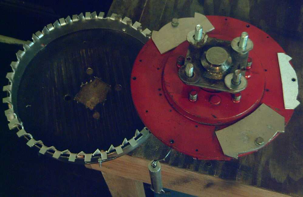 Left: Torque Converter drum with "crown" of twisted sprockets.
Right: Motor rotor with flanged axle and the first three prototype
"escapement anchors".
The washers hold the drum at the right height for the escapements to
mesh
with the sprockets.
Fish scale hanging down was to measure the torque.
The torque should vary by the square of the speed
difference between the two rotors. Either unit could be turned "freely"
at very slow speed, but at a fairly low speed the driven rotor pulled
the other around with a force of around 1 pound.
With the two anchors (the second one being heavier), the
force seemed to be around 4 pounds at 30 RPM. (Although I had a fish
scale to measure the force, the unit repeatedly jammed and it wasn't
possible to get a steady reading.) However, boldly extrapolating
anyway, that would be 16 pounds at 60 RPM, 64 pounds at 120 RPM, 256
pounds at 240 RPM, 1024 pounds at 480 RPM, 4096 pounds at 960 RPM, and
16384 pounds at 1920 RPM. That, of course, would be assuming that
nothing busted, wore out, or jammed! And the motor certainly won't
supply thousands of pounds of force, ie, it surely won't have the power
to attain those highest RPM differences. (Wasn't the Avro Arrow engine
20,000 pounds of thrust?)
I looked at the various angles and shapes of the third
prototype escapement, and started to see there was a "correct" shape,
and
that it was shaped "wrong". The square part of the edges was sometimes
able to meet the sprockets instead of the triangle edges because there
was nothing to specifically prevent it. This was the main source of the
jams. The right shape wouldn't be able to pivot into a position where
it could jam. A "wrong" shape could be made to work by attachments that
would limit its travel, but with a "right" shape, that would be
unnecessary. If I hadn't made the unit and the parts, I wouldn't
have realized there was a "right" shape and any number of
"wrong" shapes.
In a couple of days I had decided not to make the rest of
the escapements and proceed to powered trials with the "crown" gear. It
might well be that I would make them all and then have to almost
immediately make slightly different new ones to fit a new sprocket
gear. Once I
had an idea for a better sprocket gear, it was: gear first!
On the 15th after making the spot welder, I cut a new
strip of #12 aluminum, and then made a punch and die to punch the
aluminum gear teeth the way I wanted them... which was similar to the
way I had in mind in the first rough drawing except for punching them
with a 45º twist as I had done with the crown. The
differences
between this and the crown are:
a) the flats between the angled parts are retained for
strength. This will also prevent the tips of the escapements from
swinging in farther than they're supposed to - a cause of jamming of
the "crown" gear unit.
b) the holes are punched from the center of the strip and
are supported
both top and bottom - also stronger.
c) I intended to use a special punch and die jig with the
strip clamped down while punching, ensuring uniform, straight sprocket
teeth with even spacings between them.
In concept I wanted 45º triangle teeth: /\/\/\/\/\/\/\/\/\/\/\/\/\
. These would have been hard to do with sheet metal. ( - but probably
not
impossible. I was thinking that they'd have to be milled from a thick
piece of aluminum, but some jig to form it from sheet metal could
probably be created. Hmm... hmm...)
In practice: _/ _/ _/ _/ _/ _/ _/ _/ _/ _/ _/ _/ _/ _/ with 45º
angles and the same
spacings between points should work pretty much the same, though it
will
probably wear out faster. How fast remains to be seen. Could be a
minute or five years for all I know so far. The escapements, their
triangles also 45º, will hit pretty squarely against the edges, so
they might last much longer than one would suspect at first glance -
and how long solid aluminum triangles would last is also unknown.
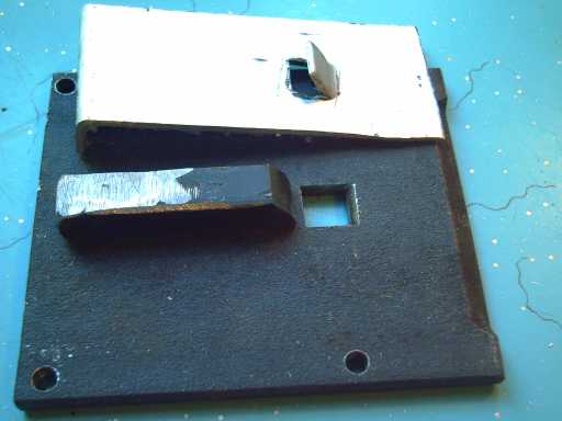 First, small sprocket punch (.5" x .5")
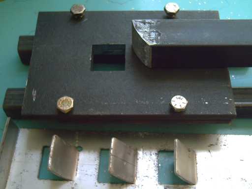
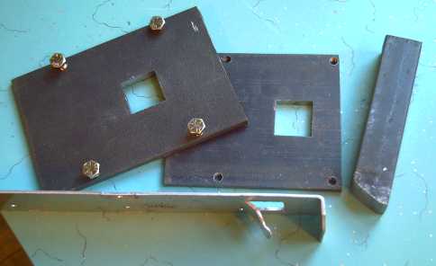 The main components of the second, larger sprocket punch & die
(1" x 1")
The main components of the second, larger sprocket punch & die
(1" x 1")
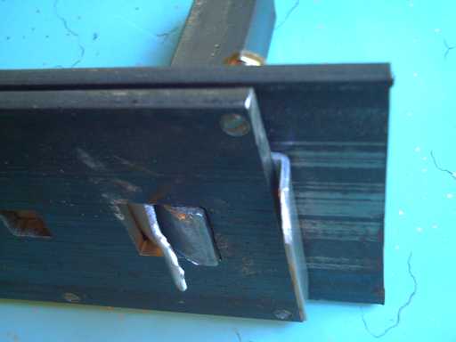 The punch at work
 Later two "rails" were added underneath so the punch could be used
on a flat surface
Later two "rails" were added underneath so the punch could be used
on a flat surface
without the teeth hitting it as they were 'extruded'.
(The astute and long-time
reader of these newsletters may
recognize that the die is made from the cut-off ends of the original 3"
x 12" battery electrode compactor, left over when it was reduced to 3"
x 6". It was handy with four holes pre-drilled and threaded.)
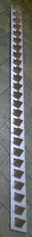
 L: 37" sprocket strip of .081" (#12) sheet aluminum with 25 teeth,
ready to bend into a ring sprocket-gear.
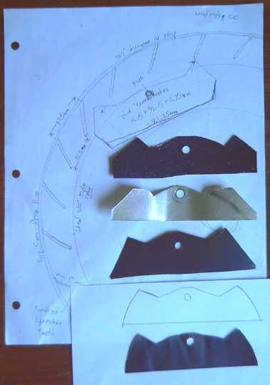
L: 37" sprocket strip of .081" (#12) sheet aluminum with 25 teeth,
ready to bend into a ring sprocket-gear.
R: Escapement piece shape trials. I finally realized they had to be
curved to account for the pivotting.
The large size teeth had their own problem: they stuck in
too far and hit the 11" diameter motor rotor - and extended to the
holes drilled
and tapped for the escapement pivots. It was necessary to mount things
so the teeth were slightly above the rotor, which fortunately wasn't
too hard to do with some sanding and by inserting some washers. I also
had to drill new pivot pin holes at a lesser radius from the center
axle.
However, for a 10"/300mm diameter rotor as I now recommend
for the motor rotor (eg 6129R),
it would be a very good fit. It makes me want to run off and change
everything
to match my vision of "as ideal as stock parts intended for something
else can get"! But I decided to leave that for motor version four since
I had other things to do, and instead (sigh) drilled another six holes
in the 11" rotor.
Rotor on axle, with 3 pivoting escapements, output drum with
sprocket strip, nylon "pipe" for bushings (inset).
It was hard trying to center the hole in the nylon rod... until finally
I remembered I have not only a drill press but a machine lathe!
It would be nice to eliminate the 12" frying pan as being
a
hard to get "custom part", and it occurs to me this can easily be done.
The torque converter drum could be made from two flat
pieces
by cutting a 12" circle of thick aluminum plate (3/8" or 1/2" thick?),
making the necessary
center and bolt holes, and then screw the toothed strip (as above) into
its edges. Optionally, an untoothed strip could cover the toothed one
to add stiffness and perhaps keep dirt out.
Or, perhaps better, a thinner circle plate could be used,
eg 1/4" or 3/16". One widened edge of the gear strip would be slotted
with "V"
slots and the tabs thus formed bent over inwards to 90º, level
with each other. This edge would be screwed onto the flat surface of
the plate all around the rim.
To get the aluminum plate round and true without a big
lathe - one able to hold a disk over 12" in diameter - it could be cut
roughly
to shape with the center parts cut and drilled, and then spun on the
motor itself to mark where to file down the outside edge to true it...
or perhaps even hold the file or some tool at the edge with the motor
turning,
though safety and technique I'd have to leave up to the user on that
idea.
On the 31st I finally had the drum and the first three
escapement pieces about ready to try, after hours of grinding, filing,
sanding and burnishing, trying to adjust the dimensions of the
escapements so they would toggle as smoothly as possible without excess
play that would have them "banging" on the teeth, but without jamming.
But when I tried it, again the force developed was wholly
insufficient. It would take more than adjustments and fine tuning to
make it work.
I'm now thoroughly sick of trying to employ the principle
of forcing masses to go back and forth at high speeds. It worked for
Constantinesco, but I'm beginning to think it takes a lot more mass,
making much more oscillating motion, than there is room for in an
"Electric Hubcap".
There has to be some simple way to create some
direct
link, something like variable gears where if "A" moves, "B" is
forcefully pushed, not indirectly coerced by an oscillating mass that
will shove
out of the way with less force than it takes to turn the car wheel.
But, now, if those same escapement pieces were being
directly shoved back and forth by the motor rotor instead of
oscillating freely, their
back and forth motion would forcefully, and smoothly, shove the same
ring gear and hence the car
wheel around... hmm - I see the glimmerings of a new plan! ...It'll
need
more pieces... Maybe it's
time to go study more aspects of mechanical clock mechanisms!
Capacitive Discharge Spot Welder
Project
Need to Weld
One of the recurring problems I've had trying to do batteries is to get
the electrodes connected to an external terminal, through a sealed
case. Solder (probably hard
solder as well as soft) corrodes away - and probably isn't a good
contaminant inside the battery. Regular welding would destroy the
pieces.
On the 15th I phoned
around to see if anyone in town was selling spot welders of the sort
commonly used for battery tab
spot welding purposes. Nope! So I
decided to check into what went into the makeup of one. At first I had
planned to visit a welding supply shop and start asking around, but I
was dubious anyone would know much about this specialized type of
welding - then
it occurred to me to check the web.
It seems the essence is a discharge of capacitors that
creates a sudden very high current through the two welding electrodes
and into the parts to be welded. The resistance to this massive current
flow is highest at the point where the two pieces touch, and the sudden
heat there simply melts the two parts
together, creating a "nugget" of weld material. So it's also called
resistance welding. Higher resistance metals like steel and nickel work
better
than the best conductors like silver, copper and aluminum, as the heat
generated at the spot to be joined is higher and melts more metal. The
electrodes, simply fat solid copper wire (eg, #4) with cone
shaped ends, were placed, then a foot switch activated the discharge. A
100-300 amp SCR is used to switch the power. However, it seems the SCR
limits the current considerably, and much more capacitance is needed.
But the whole switch arrangement can be omitted. Then the instant the
second electrode make contact the arc happens. Much skill is
evidently required for this technique.
There were commercial welders (2K$+), two-pulse welders,
welders with sophisticated solid state controls, welders made with
microwave oven transformers, electrodes which activated the pulse when
they reached a certain pressure against the workpieces, and other
refinements. One to 4.5 farads of capacitors(!) are typically used.
But the key is the spark. Discarding all sophistication, I
soldered together a rig
with four 2500uF capacitors, two leeds with alligator clips to attach
to
a 12 volt power adapter, and two leeds to the electrodes, which were
just solid #10 copper wires with the points sanded into a cone shape.
This actually made a battery tab sort of stick to a
battery. So I went out to get more capacitors. I bought two dozen
4700uF/25v ones at Queale Electronics, total 0.113 farads. Those were
the biggest they had except at very low voltage ratings. (This was all
before I discovered the massive "one farad plus" ratings others were
using. They say "try ebay" to find the capacitors.) I soldered them to
two bus
wires of #12 gauge copper wire. This turned out to be rather thin - #10
or even #8 would have been better. My unit is powered by a dinky 12VDC
power
adapter, but it's the massive current pulse that welds.)
(Be sure to get all the capacitors the same way around,
and
to hook them up the right way around every time. Polarized capacitors
connected backwards can explode with quite a bang. You could put a
diode in series with the power adapter line resistor to prevent
backwards hookups.)
I was using #16 wire about 3 feet long to the electrodes.
Results seemed unsatisfactory, and I checked on the web again. Someone
linked via youtube was boasting about how his (rather complex) welder
was only 500 micro-ohms and so could out-weld commercial models.
Another person mentioned switching from 3' of #10 to 3' of #8 and
getting better results. (I also learned that the "nugget" tends to form
towards the "+" side of the join. The positrode should go on the
thicker or lower resistance piece.)
I switched to very short #10 stranded wire electrode
leeds. It made
all the difference! Hmm... ultra-flexible #8 audio wire would be nice.
The device can still only be used to tack very thin
pieces together. I tried #26 nickel-brass and couldn't make it stick
(my battery electrode plate thickness), but when I thinned a piece in
the rolling mill (or use a hammer) to ~1.5mm (.005"), I could weld it.
The technique that seemed to work best was to press the
parts together with the positrode and then firmly tamp the negative
down onto the work, preferably but not necessarily quite near the plus.
The force with which the contact points are pressed together is
important, with too much force leading to too little heat and no weld,
and too little causing holes to be burned through the thin tab piece.
Naturally a pit is made in the work where the negatrode
touches down. (See the pitted practice battery in the picture.) I can
see how the foot pedal would be better... but this simple unit
basically works, and
can be made cheaply and quickly.
(Reading later, I see it's best if the negative is
on the thin tab piece rather than the positive. This guy seems to have
the good stuff and good info: http://frikkieg.blogspot.com/
. Seems his welder has 4.5 farads of capacitors(!), so I was on the
right track using so many myself... but underpowered!)
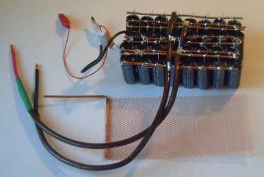
The primitive spot welder:
- 24 capacitors totaling 112,800uf (@ 25V).
- two electrodes - #10 wire.
- two clip leeds to 12 - 18 volt power adapter (observe polarity!)
- resistor (I used 3.3Ω/5W) to limit charge rate from power
adapter,
and
limits
current after initial spark.
- the fatter the wires in the discharge circuit the better.
Note
electrodes attach at center, not at an end: 1/2 the current flows
through
each side of the buss wires.
Welding practice: welded rag-tag end of a battery tab to 2nd battery -
note all the pits in the battery case where the negatrode touched
after placing the positrode on the tab at the weld point. Though it has
acquired a couple of extra holes and pits, the tab is well stuck on!
Sunglasses might have been better than just "UV blocking" glasses for
the sparks. But I soon started simply looking away before connecting.
This was quite a satisfying little project with other
projects
dragging on and on - a successful prototype in about 4-1/2 hours
including this writeup. (...writeup later expanded.) I may of course
try to
make further improvements later
to weld thicker pieces.
First Improvements: By evening I realized I could cut the
capacitor assembly in half and put it in two rows, and attach the
electrodes to both rows in the new middle. This would double up the
"skinny" #12 wire busses to give the effect of #9 wire instead. In
fact, I would only cut one wire, and fold the other one back, to make
it two rows. Say, maybe 3 rows of 8 would be even better!
I'm not sure whether adding 8 more capacitors (4 rows of
8, 0.15 F?) or getting the effect of thicker wire would have greater
effect. Certainly going from 36" of #16 wire to 10" of #10 for the
electrodes made the difference between failure and success at least
with small, thin pieces. Of course, I could do both. And I could
go up
to about 20 volts, but 16 volts from the "12 volt" power adapter seems
a more comfortable margin for 25 V rated capacitors that are being
asked to do a very hard job.
In lieu of remote activation of the pulse, a means to
prevent pits in the workpiece might be to clamp a piece of copper to
the work. Bring the second electrode down on the copper and pit that
instead. Being a low resistance, it should pit less. (Just setting the
copper on the work doesn't make a good enough connection - I tried it.)
Before month's end, I put all the above improvements into effect,
using short lengths of "#8" (really #9 ...if!) very flexible audio wire.
A 12 volt, 1 amp power adapter, hooked to the alligator clip leeds,
takes a
few seconds to recharge
the capacitors for the next zap. (In theory, the series resistor should
be 12 ohms or more.)
Copper isn't the best thing to try to
spot weld - I didn't manage to
weld the copper
electrode mesh shown to its leed wire - only to burn off some
pieces of
the mesh.
It did weld a couple of nickel or nickel-brass battery tabs quite
nicely, though if I pulled
hard enough,
all the welds broke off before the tab metal ripped. (With commercial
battery tab welds,
it's about 50-50 in my experience.)
Turquoise Battery Project
Summary
As happened a couple of months ago, I've done so much work
and writing on this project it's become a long, tedious and somewhat
disorganized report.
This time, I'll leave the text as there are many details of potential
interest to anyone working on batteries, but I think this shorter
summary just touching all the key points
is in order.
Chart shows the promise of Ni-Mn EV battery chemistry with proposed
constructions:
sealed dry cells of bipolar electrodes stacked to any desired voltage
with catalytic recombination of H2 & O2 into H2O.
Later calculation (after only a guess for the graph) showed the
horizontal placement
should have been entirely off the right hand side
of the graph: 500-750 WH/L...
and so are Ni-MH or Ni-Fe dry cells (350-560 WH/L).
The rather 'hacked' test battery under charge.
Both electrodes contain a mix of Ni and Mn for
different reasons. In fact, if one makes a positive electrode of 60%
Ni(OH)2 and 40% MnO2 'additive', it has about equal amp-hours whether
used as a positive or a negative electrode.
AFAICT, it seems the biggest difference between Ni-Mn (2.5 open circuit
volts) and
Ni-Fe (1.35
volts) is the need to add a bit of egg albumin to the manganese
negatrode in order to raise the hydrogen overvoltage to handle the
higher reaction voltage.
And this month, I was pointed to a fabulous 2004 research
report from
India on new sealed Ni-Fe batteries [www.nickel-iron-battery.com],
which mostly looked equally applicable
to Ni-Mn. A few original Edison flooded Ni-Fe cells are still in use
today almost 100 years after they were
made.
I decided to make my "full size" Ni-Mn battery with 3" x
6" flat
electrodes, which turned out to contain material for about 20 amp-hours
in 4mm (Ni+) and 1.5mm (Mn-) thick electrodes. I used copper mesh
collectors and leed wires. I started
with a "dry cell" with limited electrolyte, but the pressure rose
rapidly. (The sealed case worked great!) But I soon flooded it and
vented it, and found it would handle
much more charging current - hundreds of milliamps instead of tens.
Later, after reading the report from India, it looked like the best
thing was to initially charge the negatrodes separately in a flooded
tank, and then
use them in sealed dry cells.
A new catalytic technique to recombine O2
and H2 into water was employed that kept pressures remarkably low,
which would allow much larger sealed cells than are currently
practical. Their catalyst, however, uses platinum, which is pricey
stuff (and cerium). I hope to find one that uses economical
ingredients, like
antimony oxide.
The report also mentioned 675 Kg/sq.cm. (4.8 tons/sq.inch)
as an "optimum" electrode compacting pressure for their
iron electrodes - finally!, the first
actual figure I've ever seen on the subject. I probably get around 1/2
that in the
bolt-down compactor.
It further mentioned use of PTFE (teflon) suspension as
binder paste to "glue" the electrode together. This is probably better
than "CMC gum" and I'm trying to buy some. Seems the only place to get
it is China.
I am also wondering if it's possible to find some inert
but electrically conductive or semiconductive organic 'binder'
substance that might be both 'glue' and increase the conductivity of
the electrode, giving high current potential. Maybe that's a pipe
dream, but it would be great if a
small battery would, for example, start a car engine.
Although I used neutral pH KCl salt electrolyte, hydroxide
liberated by the charging reactions turned the cell alkaline, about pH
12 - 13. (That's still somewhat less caustic, and using edible salt
saves you from
having to work with
"caustic potash".) In the alkaline environment, the copper collector
plate and leed of the manganese negatrode were fine, but the copper in
the nickel positrode soon dissolved into green goop. Even the stainless
steel terminal bolt had some nasty corrosion. I put in a piece of
nickel-brass for a collector plate, which is faring better but not
well. By month's end there was green goop everywhere in and around the
battery. (proving it's a green energy battery!) I eventually took some
copper mesh
and nickel-brass wire to Victoria Plating and had them nickel plated
for
$70 - a bargain after the prices I'd been quoted for any sort of actual
nickel metal product. I'd rather have taken stainless steel mesh as
being naturally more resistant, but they told me that can't be nickel
plated. It then occurred to me that painting an alkaline earth element,
hmm... barium carbonate?... preferably the hydroxide, but it's hard to
make, on a
positrode metal might help protect it from alkali, so that pure nickel
might not be
necessary. Until now, only pure nickel has been made to work in
alkaline positrodes, but there may be another way. I'll be
experimenting with that.
The cell took the whole month to initially charge, and in
fact it's still charging. I
almost gave up more than once. It would go for a couple of days
sometimes without there seeming to be any increase at all, then the
third day the voltage would be a bit higher and it would hold it a bit
longer. By the end of the month it would
hold over 1.8 volts for a few minutes, and the figures were still
slowly rising. I'm wondering how much hydroxide is being converted to
carbonate via CO2 in the air with an open top for so long -- and when
that and the corrosion of the positrode plate will overtake the
charging and improvement will stop. I think all
the "green goop"
corroding off the
positrode, and perhaps impurities from the CMC gum or impure pottery
supply chemicals, is making for (as usual) very high self discharge,
and that
when everything is pure and right with nothing corroding away, it will
hold charge fine. Initially charging the Mn's in a tank should be
considerably faster and soluble impurities would dissolve out.
Again, along with the chemistry and tests is the idea
that bipolar electrodes with no collector plates could be stacked
inside to
create dry cells of any desired voltage in a single cell of almost
"ultimate"
energy density. It would also be cheapest. The edges could be sealed by
dipping the complete
assemblies in (take your choice) paint, glue, epoxy, wax... hmm,
preferably something rubbery and flexible for when the nickel 'trodes
swell a bit.
Cross Battery Checkup
I cross checked the graph figures by weighing and
measuring an actual Ni-MH battery. That should have similar amp-hours
to Ni-Mn but at 1.2 nominal volts instead of 1.9. The nickel side
is the same, and Mn gives similar amp-hours by weight to very good
metal hydrides, and the figure is in the same range as the theoretical
calculations.
The 30.5 gram Ni-MH "AA"
cell contains almost "nothing
extra" and so has almost "ultimate" energy density: 2.6 AH * 1.2 V /
.0306 Kg = 102 WH/Kg. Now account for the voltage difference: 102 WH/Kg
* 1.9/1.2 V = 162 WH/Kg. The
vertical placement of Ni-Mn on the chart
is thus approximately borne out.
An older 1.6 AH Ni-MH cell
weighs only 25 grams instead of
30, which actually accounts for almost 1/2 the difference in capacity.
1.6 AH * 1.2 V / .025 Kg = 77 WH/Kg. (not 63 WH/Kg)
For energy by volume, which I haven't tried previously to
work out, the "AA" cell measures 14.4mm (diam) * 49mm ("+" button not
included), or 5.54cc. 2.6 AH * 1.2 V / .00554 L = 563 WH/L. That's
already off the chart. Multiply that by voltage: 563 * 1.9/1.2 = 892
WH/L. Since the case will be thick plastic rather than thin metal, it
won't do quite this well, but it certainly seems I should have tried
working it out before I made that chart - these are not going to use up
a lot of cargo space! The 1.6 AH Ni-MH fares worse here: 1.6 / 2.6 x
563 = 346 WH/L. That's the only figure that's on the chart's horizontal
scale. An equivalent Ni-Mn is hardly likely to be under 500 WH/Kg,
thick plastic case and all.
I plan to try out many ideas and materials in the coming
months - starting with a more powerful electrode compactor, hoping to
get better conductivity within electrodes.
(This month's full gory details follow.)
Ni-Mn Battery
with "Full Size" Electrodes
The positrode I so casually grabbed to mate with the Mn
negative for a test battery in May turned out to be the last lanthanum
perchlorate electrode when I checked into it, rather than nickel
hydroxide. Oops! I was fooled by the greenish colour, forgetting that
not only nickel hydroxide is green, but the perchlorate is almost the
same green - slightly brighter. The battery as such didn't hold charge,
but I did find out that the manganese negative didn't seem to bubble
a lot of hydrogen.
The chemistry looked promising enough that I decided to
make a Ni-Mn battery
with my planned "full size" 3" x 6" electrodes, the size of the
compactor.
I would find out how much material makes how thick an
electrode, and hence obtain a much better approximation of how many
amp-hours to expect from what size and weight of battery.
Nickel Positrode
I decided to try for 50
amp-hours. Nickel hydroxide is 289
AH/Kg if the valence change is 1.0. With the manganese additive raising
the oxygen overvoltage, the nickel valence is said to go from about
2.25 to as high as 3.8, a change of 1.55, evidently with a considerable
proportion
of NiO2 present in the charged product. (Below valence 2.25, the
conductivity becomes poor. My batteries are starting with straight
Ni(OH)2
at valence 2.0, no doubt explaining some of the high internal
resistances.)
There is a fair level of uncertainty of what valence the
nickel will
actually attain with salt in the electrolyte. Having no special
equipment, I can only measure the amp-hours attained in a successful
battery and adjust formulations based on the result, a process so
laborious I'm unlikely to define an "optimum" mix as part of the
project.
I decided on these ingredients:
Using 1.5 valence change as a working basis, 50 AH / 433
AH/Kg = 115
grams (of Ni(OH)2).
Using half as much MnO2 as Ni(OH)2 (33%:67%), 57.5 grams
Using more monel powder (by weight) than Ni(OH)2 for good
conductivity, 125 grams.
Adding 1 wt% (of the Ni & Mn) Co2O3 for even more
conductivity, 1.75 grams.
Using 1 wt% (of the total) CMC gum for 'glue' to hold the
electrode together, 3 grams.
About 70 cc of water.
Some Notes:
* I forgot to put a thin layer of calcium hydroxide on the
collector screen as I've done with a couple of previous positrodes -
a possible way to protect it from corrosion besides making it of
nickel? I'd like to try barium hydroxide, but it seems harder to make.
It might
even help to protect the metal collector plate/leed wire structure.
* I think I'll also add the 1% antimony oxide to the positive electrode
next time, as another possible way to reduce gas pressure by causing H2
and O2 to recombine into water.
* It's amazing to start with mostly turquoise green nickel
hydroxide, mix in a couple of black things (MnO2 & Co2O3), and end
up with black - no hint of green.
* I suspected that 125g would be more monel than needed,
which
would needlessly lower the AH/Kg of the battery, but since poor
conductivity seems to have been my biggest problem so far, I just hoped
that would be 'lots'
and it would work well.
* But it turned out that the dry electrode initially had
resistance of tens of kilohms. That was completely uncharged.
Perhaps when
the Ni(OH)2 reaches a valence of 2.25, it will be considerably improved.
* Also the readings are suspect. When the ohm meter
automatically changes ranges, the apparent resistance 'jumps' by an
order of magnitude. Still, it's nothing like ohms or tens of ohms.
* I've mentioned discharging NiOOH to beta Ni(OH)2 with
H2O2. The opposite
is to charge it to NiOOH, using NaClO (bleach). I sprinkled a few drops
of
bleach to absorb in, to see if that would result in lower resistance
readings. It did seem to help, though it wasn't a big
improvement.
* I used a copper mesh and a #10 copper leed wire. The leed connected
to
a stainless steel terminal bolt. The same arrangement was okay on the
negative side, but the wire corroded right through within a day or two
in the positrode. Furthermore, where copper touched the bolt, the
stainless steel too
was corroded.
When I made the electrode from the mix, only about 40% of
the 50 AH worth of loose mix fit into the compactor with 1/2" sides. It
compacted into
a 20 amp-hour electrode 4mm thick, 145g. (140 AH/Kg. If it wasn't for
needing the rest of the battery, that would be great! The monel drags
the figure down considerably.) I could probably
up that to 30 AH, 6mm thick next time if the conductivities are good
once it's charged. Apparently a battery of 60 amp-hours equivalent to a
100 amp-hour lead-acid battery will be larger than I visualized last
month.
Since I had more than 1/2 the mixture left over, I made a
second 4mm electrode briquette, with no collector screen (134g -
remarkably within a gram of the same weight as the first without its 11
gram collector screen), to be part of
a central bipolar electrode for a higher voltage battery. My case was
fat enough for two sets of electrodes of this thickness - would I dare
try a 4
volt battery instead of 2? (I didn't.)
Depressing News:
the Hydraulic Press gets Bad
Press
...the bolt-down compacting system is Better!
When I compacted the electrode with the new 12 ton
hydraulic press, I pumped the handle until it took an awful lot of
force to push it any farther. I pressed in the middle of the electrode,
somewhat towards each end, and then the middle again. The powders
compacted from 1/2" thick as poured in down to about 4.5mm. The
electrode seemed pretty solid, but for comparison I dug out the bolts
for the bolt-down compacting system
and torqued them down. The electrode went down about
another 1/2mm to 4mm thickness.
It seems my bolt-down electrode compacting system is
better than a 12
ton hydraulic press! Evidently the only point to buying a hydraulic
press was to demonstrate this point. A 45 ton press might achieve
about the same results as the bolt tightening system... for $2000 more!
To speed up the labourious bolt-compacting process,
perhaps all I needed was an electric nutdriver, and a holder for the
compactor so I could work the driver without having to hang onto that
at the same time?
A 4.5 amp drill might hold a nut driver bit quite nicely,
and it has a lot of torque. I tried that next.
One thing I'll do differently if I make another
bolt-down compactor will be to use a 7/16" or 1/2" steel plate for the
bottom, as the 1/4" thick bottom plate bulges a bit in the middle. I
may change this regardless. The
1/4" top plate also bulges, but it pushes down the 3/8" thick x 3" x 6"
die
piece onto the electrode, which piece (I trust) doesn't flex.
Another thing would be to have even more bolts around the
edges - at least one per inch.
I'm also wondering now why I decided to reduce "full size"
electrodes from 3" x 12" to 3" x 6". Although they'll each be somewhat
easier, it means making and installing twice as many batteries to get
the same result.
Manganese
Negatrode
I decided to go with a larger amount of almost the same mixture as last
month
for the negatrode, but with just a little of the finer nickel particles
as derived from the
hydroxide. Since I'd used 40 AH worth of positive material and since
the battery should be positive limited (so it creates O2 when
overcharged rather than H2), perhaps making about 50 AH for two
negatrodes
would be about right:
Expanded copper mesh collector sheet/backing with Cu leed wire, 6" x 3"
(11.8g)
Monel alloy powder - 55g (conductivity, ??)
Ni(OH)2 - 5.0g (conductivity - reduces to Ni)
MnOOH (?) - 55g (active ingredient - overdischarged state)
Mn metal powder - 20g (active ingredient - charged state - add this
last)
Sb4O6 - 1.25g (increases hydrogen overvoltage)
CMC gum - 1.35g (glue)
Albumin (egg white) - a smear (significantly increases hydrogen
overvoltage even in PPM quantities)
HOH distilled - 15cc
Assuming the Mn has in fact been successfully reduced from
MnO2 to MnOOH, the balance is 30g of Mn overdischarged to valence [III]
and 20g charged to [0], with [II] being the expected discharged state.
It should thus take 15g of Mn to bring the 30g of MnOOH up to "normal
discharged" state, leaving 5g of 50 charged. Since the nickel side was
40 AH, that should also leave 5g of uncharged Mn(OH)2 when the positive
is fully charged. Assuming gas permeability, the migrating O2 from the
"+" side during overcharging will spontaneously discharge as much Mn as
is needed to prevent the "-" from overcharging and generating hydrogen.
One might question whether there's any value in having
undischarged manganese in the negatrode when the positrode is fully
discharged, and also whether 5g, 10% extra, is enough uncharged
material during overcharging to prevent hydrogen generation. I'm not
going to try to answer these questions at this point.
Afterthoughts:
* I found out this month that the best way to charge the negatrodes
is probably immersed in a tank, with nickel plate positives bubbling
oxygen gas.
They're put into the battery later. That means the initial state of
charge isn't important. Thus pottery supply NiO and MnO2
(assuming purity is okay) are probably as good as powdered metals, and
they're cheaper and more readily available.
* Quantities should be adjusted to account for the oxygens. (I do
wonder if the electrodes should be re-compacted after charging,
especially if the compaction pressure was low to start with. Of course,
the electrode needs space to hold the manganese hydroxide when
discharged, too - but one wouldn't discharge the Ni again of course...
or the copper mesh!)
* In the past, it has been considered that a sealed alkaline cell
should be positive limited on charge so that if overcharged, oxygen is
formed first and is converted back to water by discharging the metal
[manganese] to hydroxide at the negatrode. Generation of hydrogen,
which there was no way to eliminate, was thus prevented regardless of
overcharging. With the catalytic recombiner, it would seem more
desirable that both O2 and H2 start to be generated at about the same
time for catalytic conversion, rather than to have one or the other
form first and build up pressure. The research paper had negative
limited cells. I'd guess that equal capacities would be ideal. The Ni
side valence only goes down to 2.25, about 5/6 discharged, before the
user will decide it's not putting out very well, and it would be the
same for the Mn side, 5/6, if it had the same capacity. Thus the usual
desire to have some reserve negatrode capacity would be in practice
fulfilled.
The Mn negatrode reaction, one with the elusive
solid-solid (non-dissolving) reaction products on both charge and
discharge:
Mn(OH)2(s) + 2e-
<=> Mn(s) + 2OH- [-1.55
V; 976 AH/Kg or 1513 WH/Kg of Mn]
I neglected to weigh the electrode (with screen and leed
wire) before installing it, but it should have weighed about 81 grams.
The thickness was about 1.5mm.
Add the 145g for the positive and it's 226 grams for 20 amp-hours, or
88 amp-hours per kilogram. Since it's two volts, that's 176 watt-hours
per kilogram, considering only the electrodes. Add to that the case and
the electrolyte.
The center electrodes with no collector screens or leed
wires are about 25 grams lighter, 201 grams or 99 AH/Kg, 198 WH/Kg.
For a 12 volt battery:
201 * 5 + 226 = 1231g
20 AH * 12 V = 240 W-H
240 WH / 1.231 Kg = 195 WH/Kg
Again this is for the electrodes themselves. The case and electrolyte
will reduce this figure. However, it is perhaps instructive to note
that current lithium batteries are said to produce around 80 to 120
WH/Kg (there may be some somewhat better), and
that by adding less inert and heavy conductive metal filler powders,
lower current
but higher energy per weight Ni-Mn can be achieved.
Testing the
Battery
When the Battery was assembled, I tried charging it...
with
the usual disappointing results.
At least a couple of times I almost gave up. But
this time, fixing obvious problems that soon arose, trying a few things
and, mostly, sheer persistence
paid off, because in fact it took weeks for it to come up to its
expected voltage
and stay there when the charge was removed. Later I learned of a faster
way of 'formation' of the electrodes to get the initial charge.
First I decided to fill it with
electrolyte, a flooded cell instead of a dry cell. It worked way
better. I could put in hundreds of milliamps of charging current
instead of tens, and yet the voltage stayed much lower. I decided it
would have to be a flooded cell instead of a dry cell. (Later I
reconsidered this.)
Also the pressure crept up visibly to 5 PSI as I watched
for a few minutes.
In 2-1/2 hours it was up to 18 PSI. Through the clear plastic lid I
could see the water bubbling. I unscrewed the pressure gauge to release
the pressure. I decided it would also
have to be a vented cell. Anyway my sealed case design seems
vindicated! With a glued-on bottom, a rubber gasket at the top, and the
bolts done up, there was no sign of leaks.
There was quite a lot of bubbling for the first day, which
didn't smell like hydrogen AFAICT. This subsided, but after about a day
the currents also
dropped a lot and the charge voltage went way up, to over 3 volts. It
turned out to be
because the copper connections
of the positrode had corroded entirely away - and a piece of the
stainless steel
terminal bolt in contact with the copper was eaten away. It looks like
copper is good for the negatrode, but not on the plus side, and also
that stainless steel wasn't going to work either.
Corroded bits of copper mesh and wire from the nickel positrode.
The positrode was pieced back together, on a sheet of nickel-brass
with
a
stainless steel screen.
This was wrapped in cellophane and re-used.
So the question is what to use for connections? I
suspected the nickel-brass (AKA "German silver", "nickel-silver")
wouldn't
last either, but I stuck a sliver of it in behind the now unconnected
electrode to try it out. The battery went back to accepting high
currents without the voltage running away. I suspected that
only pure nickel was going to work for long, just like in alkaline
cells - if it worked.
Later I went down to Custom Plating and found they'd
nickel plate a good size chunk of my extruded copper mesh and a piece
of heavy nickel-brass wire for about $70. That should work except it
may corrode in from the cut ends eventually, and anywhere it gets
scratched during handling or when compacting the electrode. (Maybe
they'd plate finished assemblies for a reasonable price, too.)
Next I suspected there was a short circuit through the
separator
sheets (the Arches 90# watercolour paper and the cellophane). I took
the battery apart. I found 3 holes in the paper. I probably made the
holes sticking in the sharp sliver of sheet metal.
The negatrode
appeared to be in
fine condition. The positrode
fell apart, its copper mesh skeleton
dissolved away.
I reassembled the pieces on a sheet of nickel-brass, wrapped it in
cellophane, cut a new paper sheet, and re-assembled the battery.
Then I tested the pH. The pH was 12 or 13!
Evidently in spite of adding neutral KCl salt, I had
created an alkaline battery. That would explain the corrosion.
In retrospect it
doesn't seem too surprising, since the manganese (MnOOH - ?) gives off
OH-'es as it
charges, which will mingle with the K+'es in solution to form KOH. And
the Ni(OH)2 in the negatrode as well gives up its OH-'es one-time,
afterwards being fine metallic Ni. (I wonder what
happens to the Cl-'es? Probably they remain active in the solution,
especially seeing it isn't pH 14.) Here we see a situation analogous to
the lead battery renewal process, where starting with neutral sodium
sulfate salt in distilled water, the liberation of more sulfate from
the battery plates yields an acid electrolyte of sulfuric acid and
sodium bisulfate.
Evidently then nickel or nickel plated metal will be
required for the "+" side. I wonder how practical it is to make up my
own nickel plating solution, seeing that nickel mesh and wire seem,
absurdly, to
be 400 $/pound and up from anywhere I can find them?
This also means that the alkaline voltages from the table
should apply: +.48 or +.51 for the nickel (depending where you read it)
and -1.55 or -1.56 for the manganese, about
2.03 to 2.07 volts. Still much higher than Ni-Fe, -Cd, -MH or even -Zn!
After a few days the cell still didn't seem to want to
charge
further and come up to its proper voltage, like most of my batteries. I
decided to take it apart, rinse it out, and replace the grungy looking
electrolyte.
The manganese negatrode looked much the same as when I
made it and only a little colour was evident in the rinse bath. But as
I was rinsing it, I realized I hadn't heated it to cook the bit of egg
white that was in it. Could it have washed out or degraded, and that be
the reason it wasn't charging? If I couldn't make this battery work,
only a new negatrode would tell for sure.
The nickel hydroxide positrode, wrapped in cellophane,
oozed greenish and yellowish stuff from start to finish. What was all
that? Answering that question might also answer why the battery wasn't
performing as expected - after all, I know I had a working nickel
positrode earlier, that I had coupled with a commercial battery
cadmium negative.
Next thing to check in the replaced KCl electrolyte was the pH. After a
bit of time and charging, it was about 12, still very alkaline.
The negatrode was bubbling strongly under charge, even
worse than initially. The obvious suspect was the uncooked egg white.
A simple thing to try before making a new negatrode
suggested itself: dry the electrode, mix some egg white with water,
pour it on and let it soak in, then heat the electrode at about
110ºc in the oven for a while to cook it. I did this. Then
I
reassembled the battery cell and put in on charge. Soon it was up to
2-1/2 volts, and something like a white merangue formed above the
negatrode, which continued to bubble. It was yellow in places, where it
looked a bit like what was
leaking out of the positrode when I was rinsing it.
It still wasn't holding much more charge. I added a couple
of drops of methyl-ethyl keytone to the electrolyte. I don't know if it
helped. A day later, it was holding just slightly more charge.
The cell was, over the weeks, increasing in voltage. On
the 17th, I read a piece on "forming" iron electrodes in a flooded tank
with nickel metal "counter-electrodes" on both sides (doubtless
bubbling oxygen when charging the negatrode), even though the
electrodes were for use in a dry cell. That's probably the way it's
supposed to be done, and the way I should be doing the manganese ones.
Hydrogen
Overvoltage & Manganese
I should perhaps clarify in detail the reason for the
antimony and
the egg white. A small amount of a transition metal in the
negatrode raises its hydrogen overvoltage and this has been helpful
with zinc, although zinc does charge without it under normal
conditions. The transition element
may be added as its oxide or in pure
metal form.
Antimony looks like
the best to me and is evidently
non-toxic, and the oxide is cheap at pottery supplies. Furthermore,
there are indications that antimony (specifically) might cause a
catalytic reaction to recombine hydrogen and oxygen into water,
reducing gas pressure inside the battery. This has also been done using
cerium and platinum, but platinum is costly.
The manganese metal/hydroxide reaction is 300mV higher
voltage than zinc,
which has previously been considered to be the highest energy negatrode
substance usable in aqueous solution. Instead of the manganese
charging, hydrogen bubbles off the electrode: the water charges first.
What I've never seen mentioned in battery literature is this (Science
Magazine (23 October 1964, article: Effect
of Traces of Large Molecules
Containing Nitrogen on Hydrogen Overvoltage):
"Organic amines, present in very small
concentrations (below 10-6
M) in 0.1
N H2SO4,
cause a significant increase in hydrogen overvoltage, the
effect being stronger the higher the molecular weight. The
increase could be accounted for by the usual site-blockage concept.
In the case of egg albumin, a drastic increase of over 300
mv was observed at 12.5 ma/cm2 for a concentration of only
0.01 part per million. A new mechanism is proposed in which the
dielectric constant and hydrogen-ion activity are believed to
be depressed in a region twice as thick as the usual transition region."
Note that the "drastic increase of over 300 mV" is the
very voltage
by which manganese exceeds zinc in alkaline solution, and zinc charges.
And that increase was
given for
an acidic solution and a very small concentration of albumin. It is
probably even higher in alkaline solution, perhaps 0.5 volts or more,
and with a greater concentration. Although the hydrogen overvoltage is
different for different electrode metals, the antimony plus the egg
albumin should surely provide enough increase to enable manganese to
charge. Enabling manganese high voltage negatives in batteries using
the 46 year old albumin finding is a fine new piece of "open
technology"!
(BTW the reason
I don't use zinc is because of its problem of
migrating, and growing "tentacles" (dendrites) during cycling, via the
temporarily dissolved zincate ion. The migration of zinc to the
positive electrode gradually reduces the capacity, and often the
tentacles short
out the battery. Otherwise Ni-Zn would make great higher energy
batteries! Cadmium, right under zinc in the periodic table, has the
same problem and Ni-Cd batteries rarely last their nominal rated 200
charges.)
Reducing
Manganese Dioxide
I added plenty of H2O2 to 10.00 grams of MnO2, to try to
determine what form it became by the weight of the product. There was
lots of bubbling. Then it had to dry out. I
poured some water/H2O2 off once it settled.
MnO2 [IV] - molecular weight 87 - 10.00 g
As I saw it, the chief possibilities and their weights were:
MnO [II] - 71 - 8.16 g
Mn2O3 [III] - 9.08 g
MnOOH [III] - 88 - 10.11 g
Mn(OH)2 [II] - 89 - 10.23 g
The measured weight once it had dried was 10.05 grams.
(The resolution of the scale is only .05g.) I think it
lost a tiny amount of Mn material in the water I poured out. I think
I'll assume it's MnOOH. That's closest by weight
and a likely reaction result. The best result would have been valence
two - MnO
or Mn(OH)2. A less likely possibility is that it acted simply as
a catalyst that caused the H2O2 to decompose and is still MnO2.
Whether it's MnOOH, Mn(OH)2 or MnO2 it's about the same
weight to attain the same amount of manganese. Only the balance of
charge shifts. This can be compensated initially by the proportion of
Mn powder added, or later by charging or discharging the
nickel side - if I recognize that it's out of balance.
Note: On the 17th I found a means of independently
charging/forming the negatrode, which means it could perhaps be brought
to the desired state of charge independently of the positrode before
the battery is assembled.
Useful
Miscellaneous Notes/Conclusions
Clear Plastic Covers
I found an advantage to having a clear bottom on the
battery: most of my covers have leaked under pressure. With the clear
bottom, I can
see how well the glue is covering and if there are air bubbles or gaps.
I can also see that the glue seal is much better if the whole thing is
well clamped while it's wet (not a surprise!), which I did by
assembling the case and
screwing the top cover on.
I can see that for a production situation, it would be
much the best to make molded cases with only the top to be fitted
afterwards -- as is the case with most liquid filled batteries. Pockets
molded in to put in screws to hold the top on would be superior to a
glued-on top IMHO. Then defective batteries could be repaired. Of
course, I'm still thinking of small production. If virtually every
battery comes off the line perfect and lasts for 10 or more years in EV
use, it would matter little.
But it looks like it's all academic... Ni-Mn cases will
need to be vented and flooded rather than sealed and dry cells.
Vented Flooded Cell Cases and Battery Sizes
After trying the battery and seeing that they were going
to have to be vented flooded cells, suddenly the whole case problem
becomes much easier - it doesn't have to hold pressure.
Making the cases from flat pieces of plastic and gluing
them together (well clamped till the glue sets!) as I had tried earlier
on is probably simplest the way to go. If I or anyone gets the chelated
lanthanum perchlorate chemistry going for higher energy density and
lower pressures, dry
cells in sealed cases will likely again become a topic of interest.
And the terminals
don't have to go
through and hold against pressure without leaking. Indeed, for homemade
batteries I see no reason not to just stick the collector wires through
tight holes in the lids, or maybe loose holes and use RTV rubber cement
or silicone to
make a seal. It solves how to connect internal terminals in a way that
won't corrode - by eliminating those connections entirely.
A second aspect of vented cases is the elimination of size
constraints. Where I would have used about 3.25" x 2.5" x 6.5"
(internal) size for a 12 volt, 30 amp-hour battery that would take the
pressure, I could now go for any size, even as big as typical lead-acid
batteries, but with very high amp-hours. The one constraint is the size
of individual electrodes, which still have to be strongly compacted.
One thought would be to make a battery of the same 3" x 6"
electrodes, stacked in parallel and in series to make a single 36 volt
battery for the Electric Hubcap system. For example, a 36 volt, 120
amp-hour battery would
be four electrodes wide, 18 pairs in series. That would be (internally)
about 6.25" tall x 12.25" wide x 7.25" across, roughly the size and
weight of
one of the six lead-acid batteries that it would replace, about 50
pounds instead of 300.
A final note is that thinner plastic might be used if
there's no pressure, slightly decreasing battery weight and size. Then
again, that would apply to batteries the size I was planning for sealed
cells. If quite large batteries are to be made, they'll probably need
thicker walls.
An less final note is that after reading the Indian
experiments into sealed Ni-Fe cells, I think the catalyst idea to
almost eliminate gas pressures is admirable and that sealed Ni-Mn cells
deserve further experimentation.
Electric Electrode Compacting
Using a 4.5 amps variable speed electric drill as a
nutdriver reduced the labour of tighening and loosening all those
bolts on the electrode compactor. After torqueing them down with the
drill, I tried torqueing them further with the wrench I'd been using.
Some of them went a little farther, some wouldn't budge. If there were
just a few more bolts around the edges, eg one per inch or per 3/4
inch, it would have
been better compacted than with the wrench, with less effort and less
stress on each bolt. But it seemed good enough. I stopped using the
hand wrench.
The chief problem was holding down the compactor. I ended
up with it between two C-clamps, but once it got away and the spinning
compactor sent tools on the workbench flying around.
Another problem with the compactor (I may have said this
elsewhere) is that the 1/4" steel bulges when the bolts are done
up. The next compactor will use a 1/2" steel base.
Later I added 6 more bolt holes to the compactor, bringing
it from 14 to 20 bolts. The spacing is rather irregular, and on this
compactor it would be hard to fit any more.
Reading a Ni-Fe battery experiment paper, I see they
compacted the Fe electrodes with 675 Kg/sq.cm, or 4-1/2 tons per square
inch. If my compactor is roughly equivalent to a 50 ton press,
50/(3"*6"=18sq.") = 2.7 tons/sq.inch. That's just over 1/2. But it's
the right ballpark, anyway, the right order of magnitude.
They left the pressure on the electrodes for 5 minutes.
Maybe if I just leave the box screwed together for 10 minutes...
(Warning! Faulty logic alarm!!!)
I sensed the desirability of making the
new
box with a 1/2" steel plate base (forget 3/8"!) and more bolts as
closely spaced as
practical
around the edges, and I bought the metal to make it, with a bolt every
5/8".
On the other hand, one must consider that nickel
electrodes swell inside the battery - alpha nickel oxyhydroxide
theoretically takes up to 44% more space than beta nickel hydroxide.
(This is counterintuitive since fluffy nickel hydroxide actually has
more hydrogen atoms in it than oxyhydroxide. The oxyhydroxides must be
really fluffy!) The electrode then, compacted to satisfaction, somewhat
uncompacts itself. (10-20%?) How much compaction then, is really useful?
Naturally I want to make electrodes as large as is practical -
I'd do 12" x 12" if I could, and maybe have one battery for the whole
car. The gas pressure in sealed cells precludes such sizes. But if the
compacting pressure is insufficient for 3" wide electrodes with good
conductivity, one could make them 2" wide and get 1.5 times the
pressure with the same force, 1.5" wide and get twice the pressure, or
even 1" wide and get 3 times the pressure. If that sort of solution
becomes necessary, I might end up doing foot long, skinny electrodes in
narrow squared-up pipes. The idea could be tested using smaller inserts
inside larger compacting boxes.
Or perhaps there are other simple means of compacting
electrodes. For example, the force could perhaps be doubled by
compacting 1/2 the width at a time - if that didn't break the electrode
in half. (A gradual bend at the "middle" edge of the die?) Or perhaps
some sort of pressure roller arrangement, though I haven't come up with
a design I'd have confidence in myself.
Collectors/Leeds
The copper leed wire on the negatrode looks fine, and the
expanded copper mesh collector is still holding the negatrode together
after a month. Given that it seems to work, copper should be the best
material given its high conductivity.
The one from the plus
side soon had such a coating of copper oxide it looked like it had
green
plastic insulation, then it and the mesh inside the
electrode corroded away altogether. I'll have to try other materials.
There's the stainless steel mesh for the positrodes next
time, and nickel-brass wire. If the wire corrodes but not the mesh I
can doubtless
find stainless wire. If stainless corrodes I guess nickel plated (or
__?)
mesh will be necessary - with nickel plated wire if the nickel-brass
also corrodes.
I put the present 'positrode' back together with a
nickel-brass
plate wrapped in stainless steel mesh. We should know soon enough.
I've been setting the copper or stainless mesh in the
bottom of the compactor
so it's at the rear of the electrode, but it occurs to me the best
internal connectivity, and the best strength, will result if the mesh
is in the center. It's hard to resist the mental temptation to think
the wire should be at the back, but in fact the mesh permits
electrolyte ion flow penetration, and the ion flow in the electrolyte
and the electron flow in the wires are unaffected by each other.
If the mesh is in the middle of a 6mm thick electrode, no
part of the electrode is more than 3mm from it, instead of up to 6mm.
The ions still have to penetrate 6mm either way.
Tentative layers of the battery would be:
-- nickel-brass plate
-- stainless steel mesh grid (with calcium hydroxide?) If nickel mesh
was available that would be better.
-- nickel 'positrode' material as detailed above
-- all of above wrapped in cellophane with one layer facing 'negatrode'
-- sheet of Arches 90# watercolour paper or equivalent
===
'optional', for multi-cell batteries of any higher voltage, multiples
of two layers compacted together:
-- manganese 'negatrode' material: no connection leed, no collector
mesh -
just the plain briquette
-- (Thin calcium hydroxide layer?)
-- nickel 'posode' material - just the pure briquette.
-- this "bipolar briquette" wrapped in cellophane
-- sheet of watercolour paper.
===
-- manganese 'negatrode' material as previously described, compacted
around expanded copper mesh, with #10 copper leed wire
(leed wire flattened and wrapped into a folded edge of the
mesh, left round at terminal end)
I'm considering whether edge sealing might be done by
something like wrapping electrodes in a "U" shape with cellophane and
heat gluing the edges to form bags with open tops. Or perhaps make
cellophane bags separately and slip the 'trodes into them.
A way to get surer separation with the paper might be to
fan-fold it left and right between electrode pairs.
And, with a
little paper overhanging at the bottom (of course!), perhaps dip it in
tar or paint or epoxy or wax or something rubbery to seal the whole
bottom edge, and perhaps the
sides.
July 29th: The nickel-brass is still getting corroded in
the positrode. I've replaced another n-b sheet 'leed' after its remains
had fallen off. This time, I used a nickel plated wire (of
nickel-brass), though I had flattened it and tried to weld it since
having it plated, so it could hardly be said to be truly protected.
Real Watt-Hours
The nickel-manganese test battery - with one cell in it
but room for two - was 822 grams: thick plastic case, electrodes,
excess water, internal plastic space fillers and all:
20 AH * 2.2 V / 822 g = 53 WH/Kg. (Final batteries will
perhaps triple this figure!)
Even with all the waste weight, it already compares
favourably with (properly derated) lead-acid at: (40 * 0.6 =) 24 WH/Kg,
or with the Changhong 10 AH size nickel-iron battery:
10 AH * 1.2 V / 625 g = 19 WH/Kg.
Show me the Money!
John McCain wanted to offer $45,000,000 to anyone who
could come up with a better battery for EVs if he became
president of
the USA.
But he lost the election, and perhaps it wouldn't have
been available to a Canadian anyway. In the usual course
of events, the inventor is left to starve as his invention
spreads over the world... or for various poor reasons goes to waste.
Electrolyte Reaction Comparisons
With Ni-Mn, Ni-Fe and Ni-Cd, the net result during
charging is that hydrogen comes out of the nickel hydroxide and and
hydroxide comes out of the "-" side, making H-OH, water. The Changhong
Ni-Fe cells are visibly fuller (about 1/8" in the 10 AH size) when
charged than when
discharged.
With Ni-Zn, the ZnO (which evidently forms instead of
Zn(OH)2) "-" gives off its oxygen, also making water with the nickel's
"H"es, though half as much.
With Ni-MH, the H's from the nickel "+" are simply packed
into the hydride negatrode alloy's 'pores' and the net water content
remains
the same.
With the chelated lanthanum chloride/perchlorate
chemistry, the "+"
side oxidizes by absorbing oxygen during charging instead of by
releasing hydrogen. If that's coupled with (eg) manganese, the two
OH'es from the Mn(OH)2 yield the O it needs and an H2O, but half as
much water as with a nickel positrode supplying more hydrogen. As well
as
replacing the bulky, heavy nickel side of the battery with much less
material for the same amp-hours, this is the chemistry I hope will have
lower gas pressures as sealed dry cells. Alas, I must leave its
development for later or for someone else. I've created the concept and
many techniques which may be employed in its implementation and
published it all in these newsletters, with increasing clarity of
concept over time from the initial muddy ideas. I hope that's enough
that its development can be completed, and that that will be done in
the same "open technology" spirit with which I started it.
I expect the
perchlorate chemistry would have tolerably
low pressures and could be sealed as dry cells, but Ni-Mn is still an
improvement over anything else out there. For this unpaid researcher
who needs to move on, Ni-Mn will do.
Separator Sheets
Real cellophane ("Pacon creative products, Cellophane" -
from Island Blue Print) seems to work well as a microporous membrane to
wrap up an electrode. Beware of plasticized "cellophane", which is
non-porous! The Arches 90# watercolour paper (from Opus Picture
Framing) makes a great "non-woven" separator sheet, a uniformly thick
and dense mat paper with wet strength including in salt and in alkali.
Both of these were found at art supply stores.
Side Thought: High Energy Density Nickel-Iron
As I think about it, it seems a puzzle that no one has
ever made high energy density Ni-Fe batteries for automotive use. They
would be cheaper than Ni-MH, long lasting, and as a century old
technology no patent
can be used to kill them. The reason they're only 20 to 40 watt-hours
per kilogram as made today is largely because of the construction, and
also because the "Ni" side chemistry hasn't been updated: they're made
only as
"pocket batteries" almost the same way Jungner and Edison made them 100
years ago.
The perforated metal plates weigh perhaps as much as the electrode
material they contain,
and the open spaces between plates are filled with quite a bit of
water. And then because it's all so much bigger than it needs to be,
the
cases are heavier. This construction is also quite costly compared with
modern types.
It seems to me that Ni-Fe batteries with an energy density
of somewhere between 70 and 100 watt-hours per kilogram
could be made simply by making them with the same sort of electrode
briquettes as for Ni-Cd et al,
compacted around nickel foil or mesh to replace the heavy exoskeletons.
The higher end of these figures, not out of line with the best EV
batteries currently available (at a much higher cost!), would apply if
my electrode stacking
construction (topic above) was applied and with the best modern "Ni"
formulations.
Of course, all this is suddenly redundant just as I write
it, since Ni-Mn
should provide a very similar low cost battery with
almost twice the energy - judging by the chemistry and characteristics
of
manganese as far as I can tell and the stated efficacies of the
techniques I've hunted down and employed to raise the hydrogen
overvoltage.
I think the fact that high-energy nickel-iron
was never done shows just how little creative thought has gone into
battery development, in spite of intensive battery research
efforts (mostly geared at pricey lithium types). Everyone
seems to take the development side of "R & D" almost entirely for
granted, assuming that once the principles for inventing something are
discovered through
research,
there's no need to support it - development to the "invented" state
will happen "by itself". Here
is a case! While people have long struggled to find decent, economical
batteries for
electric & PHEV vehicles, a good, practical working solution has
been
sitting right under our
noses for almost half a century, simply for want of being developed!
New Nickel Iron Sealed Dry-Cell Battery Research - Equally
Applicable to
Nickel-Manganese!
After writing the above, I found recent research (2004
report)
that has been done to make a sealed, maintenance-free nickel-iron dry
cell. No
figures were given in the paper for the energy density, but it appears
it was essentially the sort of battery I wrote of above - even better.
It also says
the authors didn't know of any similar research ever having been done.
It is exciting and promising. The only down side is that a
new catalyst that keeps the gas pressure amazingly low (hence allowing
the sealed cells) contains platinum, which can't help the economics.
The fact that this valuable research was done in India
shows not only that there is creative genius in that land, but,
considering how badly we need such batteries, the
unfocused disarray which is the state of R & D in the west. A
critical eye overseeing battery technology and allocating research
funding would have seen, or at least been receptive to the idea, that
Ni-Fe with modern constructions was an undeveloped area worthy of
research, and probably of development to commercial stage even without
sealed cells.
If now the Indian government has followed up by helping to get the
sealed cells
commercially produced, the west could soon be importing its best EV
batteries from India.
This study was located via a new information page from
Victoria BC, www.nickel-iron-battery.com
. It looks like I can probably do maintenance-free Ni-Mn sealed dry
cells after all! A catalyst without pricey platinum would be an
advantage, and that alone should bear more research.
Binder/Glue
The above experiment also mentioned using "6 wt% PTFE
Fluon Suspension" as (presumably) the binder to hold the negatrode
together. PTFE has also been stretched to make microporous separator
sheets used in batteries (not to mention in gore-tex).
Previously I'd seen "not more than 1 wt% CMC" as a figure and
material to use. I presumed this to be the same as "CMC gum" from the
pottery supply, and presumed them both to be sodium carboxy methyl
cellulose. I had also purchased a bag of "Veegum", a bentonite clay
mix, to try out.
So I I thought I should try to track down a source for
PTFE suspension -
it's probably better, and it would seem you can use more of it,
presumably making physically stronger electrodes for handling until
they're in the battery, without causing other problems.
Also, they mention rolling out the 'putty' electrode
material into
a sheet (and then folding it over the mesh, which would get the mesh in
the middle as discussed above) before compacting it. Rolling the
'dough' form would help get a uniform thickness and hence uniform
compaction, which I didn't get on the first large size manganese
negatrodes - there were 'thin' spots that weren't well compacted.
Next it occurred to me that both those binders are
insulators. If one could find a stable but electrically conductive, or
even semiconductive, binder material, the electrode would handle far
more current, even with less compaction. "Small" batteries with the
3"x6" electrodes might start your car instead of providing only tens of
amps. Perhaps now that I have a working chemistry, I'll go back over my
earlier experiments with acetal ester and the like, and see if any such
binder can readily be made.
It's doubtless worth finding the best possible binder. An
electrically conductive one would be another 'coup' for this project.
And of course I'm going
to try doing those bipolar electrodes with no 'backbone'
whatsoever, and they have to hold
themselves together, which the CMC isn't going to accomplish.
http://www.TurquoiseEnergy.com
Victoria BC