Turquoise
Energy Ltd. News #31
Victoria BC
Copyright 2010 Craig Carmichael - September 1st 2010
http://www.TurquoiseEnergy.com
Contents/Highlights:
August in Brief
(summary)
* Workable design for Mechanical Torque Converter, and working
electrochemistry for economical high energy Ni-Mn batteries - and even
"dirt cheap" high energy Mn-Mn batteries: Now it's down to
implementation details... though a few of them are still pretty
challenging.
* With the torque converter "in sight", I think it's time to
start pushing ahead with adoption ideas - like getting motor
controllers made, custom cut steel and aluminum parts, and motor making
workshops.
* Pulsejet steel cutter - potential project - or tool?
Designed to be
jet engines with no moving parts, pressure pulsed flame might make a
great steel cutter. Use
free-form for prototyping, or on CNC machine for automated cutting.
(for the
custom cut parts mentioned above.)
Electric Hubcap Motor Making Workshop
* Finally Going Ahead. Self-paced, flexible hours per participant
needs. Please
Call!
* Cost $1000 includes motor parts, supplies (further details on
web site).
* Accommodation here for out of town workshop participant, $150
per week.
* Explore commercial possibilities for making motors, motor
controllers, parts for them, install systems on vehicles, etc. (There
have already been a couple of offers to buy finished units.)
Torque Converter
Project: a Working Torque Machine
* The mechanical torque converter is in fact a new type of
machine to add to
the "classical" machines:
Lever, Wheel and axle, Pulley, Inclined_plane,
Wedge, Screw,
Hydraulic pistons, Torque converter.
* Quick experiment & calculations indicates oscillating
masses torque machine really ought to
be feasible.
* Weighted escapements experiment (136 grams versus 36) shows...
* It
works! "Clock Escapement" type
torque machine provides motive force.
* Ideal shape of converter drum: a "bowl shaped" convex bottom?
- EH unit would pivot more smoothly when car wheel hits bumps.
* Gears... all these problems and considerations, bypassed by
the
torque converter!
Turquoise
Battery Project
* Nickel plating dissolves off collector screen! - Inquiry
reveals "brighteners" are added to the plating, so it actually is not
pure nickel!
* Sodium Silicate and Calcium electrode binder?
* Graphite Collector Plates: Cheaper, more available
than
nickel, simpler than nickel plating.
* Commercial lightweight "expanded graphite" sheets seem to work
without corroding!
* Hard electrode shells with "caramelized" egg white?
* Mn-Mn: DIRT CHEAP 'everlasting' high
energy 1.8 volt batteries.
* Expanded graphite sheets, carbon (graphite) fiber &
mat, carbon powder: the keys to a great, very conductive positrode!
* Alkaline pH turns neutral, Ni-Mn voltage rises: ~~2.25 V -
15%
more
energy.
* Bolt-Box Electrode Compactor Mark II - "how to"
instructions.
* Design ideas for "production" batteries.
Newsletters
Index/Highlights:
http://www.TurquoiseEnergy.com/TENewslettersIndex.html
Construction Manuals for making your own:
* Electric Hubcap Motor
(latest rev. 2010/02/xx)
- the only 5+ HP motor that can easily be made at home?
* Turquoise Motor Controller (latest rev.
2010/05/31)
- for the Electric Hubcap. (Probably there are commercial
controllers that would work, too.)
* 36 Volt Electric
Fan-Heater
- if you're running your car on electricity, you'll want a
way to defog the windshield and keep warm.
* Lead-acid battery longevity treatment - "worn
out" battery renewal procedure.
* Simple Spot Welder for battery tabs, connections (in TE News #30)
all at: http://www.TurquoiseEnergy.com/
August
in Brief
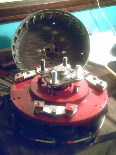
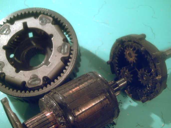
Electric Hubcap motor with prototype torque converter escapements.
Behind, drum with angle-toothed ring gear.
Tic-toc! The "clock escapement" type of torque
converter
design seems to work! Last month's unit was re-tested on the car with
just 100g of weight added to each of the three
escapements (as shown above), just to get an
indication of whether the design was worth pursuing. Unexpectedly, the
torque was sufficient that it would have got the
car rolling on level pavement if the wheel hadn't been jacked up.
With heavier masses or six escapements instead of three, it would
surely start rolling even up hills. But the big ring gear teeth folded
up quickly when it was run in reverse, ending tests without an actual
try to move the car.
A somewhat more robust "fanfold" gear was made. It held up
much better but the forces seemed lower. Put to the test, the car just
moved - it was
on the verge. Improvements as to details and proportions
are needed.
Then it should move
cars - probably even squeal tires once it's really optimized.
Near the end of August I realized this is essentially a
new type of "basic machine" to add to those mostly known since
antiquity - lever, pulley, wedge... ...the
torque machine. I think I like
the name. "Torque converter" is a very fitting name, but of course
everyone immediately thinks of those horrible hydraulic things
perpetrated by the auto industry.
It was disappointing to find my nickel plated mesh and
wire dissolving away in the battery positive electrode. I found out
that the electroplating shop doesn't use pure nickel. I thought "Every
metal disintegrates, and I can't seem to buy pure nickel or even nickel
plating. I need a whole new approach." Then it struck me: Edison used graphite
powder to increase the conductivity of his earlier nickel hydroxide
positives; so did the recent India research... that meant graphite
must survive where all the metals don't.
Couldn't one use a graphite sheet for a current collector plate
and forget the nickel metal entirely? Sure enough - it works! Plus,
graphite
powder can be had at a local art supply, and ready made graphite sheets
are
available on line. I bought some powder, made a couple of sheets in the
electrode compactor using sodium silicate as binder, and ordered
samples of commercially made "natural expanded flexible graphite"
sheets. These proved to be excellent, with low electrical
resistance and very light weight. They even look metallic silver gray
like a metal instead of black (the image below caught them in a bad
light), and unlike pencil graphite leave no
smudge. I tried one out and it seemed to solve the corrosion
problem. Graphite (carbon fiber) mat seemed a good solution for an
internal mesh, and again is available locally (@ Industrial Plastics).
It also struck me that in addition to 2.3 volt Ni-Mn
batteries, one could make 1.8 volt Mn-Mn batteries with no pricey
nickel in them at all and still about 80% of the energy density. Such
"dirt cheap" everlasting, high energy batteries have broad implications
for energy storage.
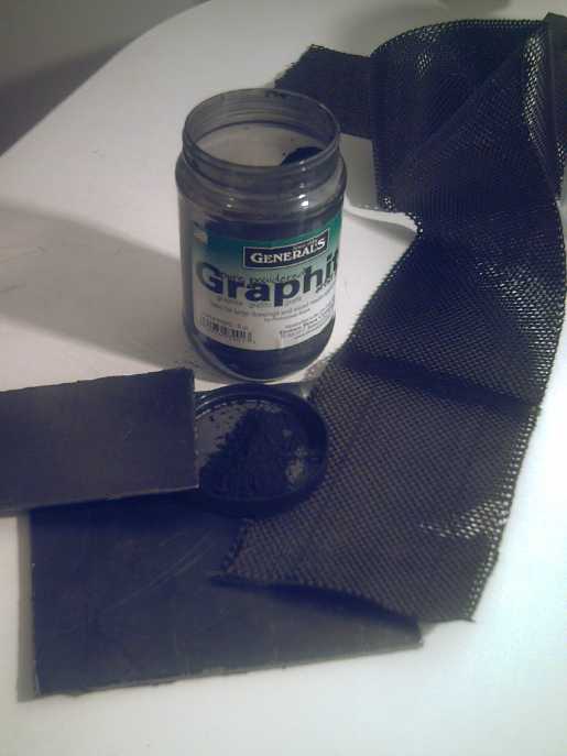 Conductive Graphite - sheets, fiber mat, powder:
my key material for non-corroding 'positrodes'.
While there are details to sort out before having
practical, working models, after a year and more of setbacks, "duds",
and the feeling the main projects had all become hopelessly mired in
mud, it is
heartening to finally have what appear to
be
workable designs for both a mechanical torque converter suitable for
the Electric Hubcap system, and two 'green', economical, high energy
battery chemistries with workable materials to make them.
I think it's finally time to resume the long delayed workshops
for building the motors (including the torque converters) idea,
with
the assumption that by the time they're actually underway, a practical
torque converter
"production prototype" will have been built and tested, and can be
duplicated. I'm
working on that now...
For those interested, current plans are that $1000 gets
you a self-paced workshop including parts and supplies (over $400
worth), and you leave
with your
Electric Hubcap motor and torque converter, ready to install on your
car. I expect to have the motor controllers available for $500, or
there'll be a motor controller making workshop if your
soldering skills are good. Times and dates will be flexible. I have a
room to rent for $150 a week to crash in should anyone wish to
come from out of town and
perhaps devote full time to doing it as a "crash course".
Even with the motors being made by hand, this is much the
most economical and practical way to turn a car electric. Expect
small business opportunities to open up for making and selling the
motor
systems and perhaps the controllers - there are already interested
customers - and also for installing them in
vehicles. I'll probably be offering various components to facilitate
the process.
Speaking of "various components", custom cut motor stators
and rotors of 3/8" plate steel would be great. My plan was to take
designs
to a CNC waterjet place, but someone has introduced me to pulsejets,
which were designed as jet engines with no moving parts. However, it
seems to me that a with small one it may be possible to
make a pulsejet steel cutter burning propane or MPS gas that would do
the job. The jet pressure pulses would drive the flame through the
steel, and oxygen would be unnecessary.
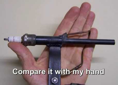
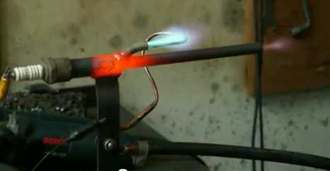
A small pulsejet device, two variations from a you-tube video.
Needed: transfer most of the heat from inside to the nozzle to cut
through steel plate.
A Mechanical Torque Machine:
At Last, Torque Leverage Without Gears!
Electric Hubcap motor with torque
converter having weighted escapements,
output drum behind with sprocket toothed gear.
The hookes on the escapements fit just between two tooth points
(three teeth apart), causing the escapements to oscillate back and forth
as the motor rotor turns relative to the drum.
The continually forced changes of momentum of the escapements'
masses provides the torque that drives the drum
- independently of the motor's own torque.
This torque converter essentially works. I'll start with a
couple of
thoughts on torque converters:
1. When the car speeds up with a geared motor, the gears as well as the
motor speed up. With this torque converter there are no static,
stationary parts; everything spins with the motor and wheel. The speed
difference, or precession, between the motor and the wheel is
dependent only on the torque required regardless of vehicle speed.
Thus, where gears may be spinning madly and making a lot of heat on the
highway, the spinning torque converter is loafing along (precessing)
little faster than at low speed. The transmission gears need to be in a
bath of oil to prevent overheating; the torque converter (hopefully)
just needs grease, solving all those problems of inefficiency
generating heat, and then oil lubrication to cool the mechanism and
generating fluid friction and more waste heat.
2. How can a torque machine provide more torque at the output than
the motor has at the input? It works by oscillating masses. In
the "clock
escapement" type of torque converter, the masses that oscillate are the
escapements. These drive the ring gear and hence the car wheel by their
inertia. The power to spin the escapements comes from the
motor, but it's the mass and speed of the spinning, oscillating
escapements that provides the torque to the output drum,
independently of the motor's own torque. This provides a variable 'n'
to 1 "gear ratio", where 'n' is always greater than one. At the risk of
being repetitive, the more the torque required, the greater will be the
difference in speed (not a ratio of speeds) between the
motor and the wheel.
The ratio difference will depend moment to moment
on the speed
difference of the motor and the wheel, and hence
will gradually drop as the vehicle speeds up, being a very high ratio
at very low speed and a low ratio at high speed - the exact desired
effect.
The day after I sent newsletter #30 saying "Torque
Converter Design #5"
had way too little push, I considered that the light aluminum
escapements had very little inertia. They could have a
"pendulum", the real inertia piece of any clock.
The force was so light in that test that it seemed simply
making heavier
escapements and doubling them from 3 to 6 could by no means bring the
forces
to the required order of magnitude. But if an arm with a weight could
be "suspended" on a
pendulum - in this case "suspended" perhaps meaning "flung outwards by
centrifugal force" - from
each one, the required "vastly more" force might actually be
forthcoming.
An escapement piece weighed 36 grams. If the weight
weighed, say, 720 grams, that would be 20 times the inertial moment. If
also that weight was out on the end of an arm, it might average 4 times
as far from the pivot center, so it would oscillate 4 times as fast
(average). E - 1/2
MV^2, so that would be 16 times the inertial energy. 20 * 16
= 320 times as much force. Doubling the escapements from 3 to 6 could
then make it 640 x. Shorter escapements, spanning 1-1/2 teeth instead
of
2-1/2, could cause greater pivoting angles and hence greater
oscillations of the
weights. Thus a gain of up to 3 orders of magnitude more force could in
fact be
realized - however much was needed, grams to kilograms. That just might
bring the forces into
the
range of "car moving".
However, adding so much weight and fitting arms on was
easier said than done. How could I get pendulum
arms through from inside the drum to outside?
As a preliminary experiment, I took an escapement and ran
it loosely around the rim of the drum, holding it by the pivot bolt. It
swiveled back and forth as it went around, but the force was small.
Then I contrived to stick on about 200 grams of steel pieces. The force
was far greater. It readily turned the drum on its axle against
friction even
at quite low speed, which the escapement with no added weight barely
did at a considerably higher speed.
Perhaps sufficient weight could be attached to the
escapement pieces on the inside to at least make a worthwhile live
motor test on
the car? If the jacked up wheel spun with sufficient force, then I'd
have a feel for whether it was worth trying to devise a real design.
Speeded-up Masses?
On the 17th it occurred to me that if one edge of the
escapement had gear teeth, and it was made to turn a small weighted
gear back and forth at high speed, the inertial effect of the mass of
the gear would be tremendously magnified. Which reminded me that I'd
been intending to study mechanical clock and watch mechanisms in more
detail. But perhaps this was the key right here. Sounded complicated,
though, and would make some heat.
This whole idea proved to be unnecessary, superfluous.
Experiment August 18th: Surprise - The design concept seems sound!
I bolted some little steel weights to the escapement
pieces "as-is" to see
how much force that could make with a live motor test on the car. The
escapements' mass
went from 36g to 136g each, with the extra 100g being two 50g weights
near
the outside
edges. (per the photo above.) When tried on the car, the jacked-up
wheel had far more push
than without
the weights - not enough to move the car, but then that wasn't expected
- it
was just to get a feel for it. It seemed that with the heavy "pendulum"
mass, or the geared speeded-up masses, the force could be made
sufficient.
However, the batteries I used
were low, especially one of them. I thought I should charge them up and
try again.
With fuller batteries the force was 5 or 10 times greater.
I couldn't hold the car wheel back
by
hand when I turned the motor right up - that was quite a surprise! I
estimate the torque I felt was greater than that needed to turn the
wheel by hand and move the car on level pavement (which I did later for
comparison), ie, that it would
have got the car rolling. (I really should figure out some way to
measure
foot-pounds at the car wheel!) After the several designs I've tried
that had much less push than expected, this one was the opposite!
I was already concerned about the sprocket teeth - I could
see tiny flecks of aluminum coming off. Next I tried running it
backwards. That proved to be a mistake: the 45º teeth all bent
away and let the escapements spin freely past. I tried pounding them
back with a hammer and screwdriver, but I didn't get them all the way
back and now even going forward they
bent out again, after providing one more burst of considerable torque.
If I bent them again they'd surely break off.
That ended the experiment, but the "clock escapement torque converter"
concept has been proven to work. Later inspection revealed the the
sharp points on the leading sides of the escapements had also been worn
to unsharp, just slightly rounded.
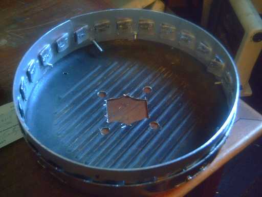
Drum - ring gear with bent-in teeth.
So! from almost nothing
without the weights to car-moving force with 300 added grams.
More mass and more escapements are probably needed for the
desired "tire squealing" push, but from the good force seen and felt in
this experiment it appears the amount or quantity needed is maybe 4x to
8x rather than 25x or 250x -- the design seems practical with the
configuration almost "as is".
The challenge
now will be to design and build an improved unit that's robust enough
to handle the forces and last a long time.
The aluminum sprocket teeth were wearing quickly, and as
noted got bent in running in reverse, where the escapements pushed
against the
face rather than against the edge. But the escapements' contact faces
were only slightly blunted. The escapements were .1875" (3/16") thick
aluminum and the
sprocket teeth only .08". But if the escapements were, eg, .375 or .75"
thick,
that would spread the contact with the sprockets over two or four times
the
width, reducing the force of the actual contact by 50% or 75% -
assuming
everything contacted squarely.
Part of the problem is doubtless that there was too much
play. The excessive slack allowed parts to hit each other with force
instead of 'meshing' smoothly with each other.
More precision is required, and more strength. At first I
thought I'd better use steel. But that seems less smooth. It rusts
(making it abrasive), it's heavy,
and it
doesn't dissipate heat as well. I decided to stick with aluminum until
and unless it definitely proved to be impractical, in which case
stainless steel might be necessary.
So then I thought
I'd try thicker aluminum
for the gear, say .125" or .15" instead of .08" so it wouldn't bend,
and
thicker aluminum for the escapements, say 3/8 or 5/8" to spread out the
contact pressure.
Then I thought of taking a strip of the .08" aluminum and
folding it up in accordion folds one inch apart, each fold 90º
(± the rim curvature) to make the 45º teeth. I could adjust
the angles minutely to set the precise distance between each two teeth.
Regardless of direction the escapements would press on an area wider
than just a thin edge, and also against the end of a wall, which would
take a lot of force to buckle.
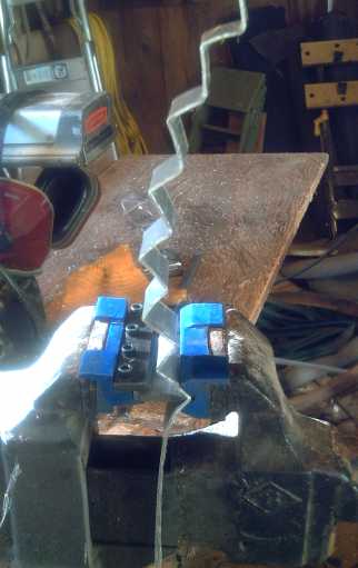 I bought this vise-mounted sheet metal bender to make the fan folds
The usual types of benders won't work for these bends, and even
this setup had to work around the center of the vise.
The exact shape and
configuration of the contact areas of
the escapements probably need to be more carefully determined so as to
eliminate
regions of 'slop' in the mechanism so it will all mesh fairly smoothly.
(It looks to me like the points should be slightly closer together and
I'll try that on the next one - the 6th one.)
The
prototype made a lot of noise, so I don't think it was there yet. The
steel stand-offs (oversize nuts) in the middle adjacent to the pivot
points were probably hitting the ring gear teeth. However, judging by
where the
wear was, this didn't account for much of it. But I
changed to thinner stand-offs of brass pipe, and sanded down the center
area of two of the three escapements a bit more. Another factor I found
in the "poor fit" was that the frying pan isn't quite round or quite
centered, and this actually made escapements that went around 85% of
the rim fine jam on the other 15%, so they had to be filed back more -
making a sloppier fit on the other 85%. An accurately made drum would
naturally be better.
Then of course the optimum amount and distribution of mass
on the
escapements still needs to be determined. However, it would seem from
the
experiment that the weights required will easily fit within the drum,
'under
the hood' - no "pendulums" sticking out, no geared-up masses, will be
needed.
I am also concerned about the small nylon bushings the
escapements pivot on, and the small 1/4" bolts the bushings themselves
pivot on. There isn't, as made, room for ball bearing races. That would
require moving the pivot point away from the gear and, at the very
least, changing all the angles and curves already rather laboriously
worked out. Perhaps the thing to do is to make plates that extend over
the tops of the escapements, so that the bolts are supported at both
ends.
Or, I could simply switch to fatter bolts. I might get
away with 5/16" - maybe - but 3/8" or more would certainly mean
slightly moving the pivot holes and modifying the escapement shapes so
the center doesn't hit the teeth. On the other hand... none of the
bolts or nylon bushings have actually had any problem so far. Maybe I
should quit worrying about it unless they do!
On the 27th I had the new 'ring gear' made, with accordion
folded aluminum. (or is it fan folded?)
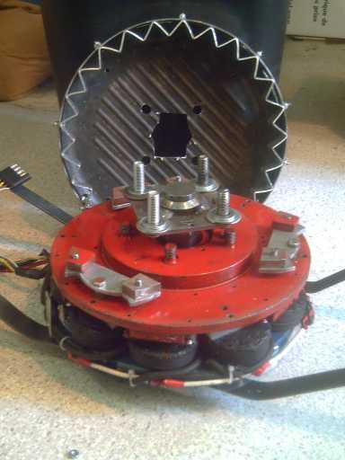 The fan-fold ring gear.
The torque was fair but it didn't seem as impressive as
the first
time. The only explanation I can think of is that although every third
tooth is bolted to the rim of the drum, there was doubtless some
"spring" to the other two which might have limited the force
transmitted, whereas on the first gear in the forward direction, the
teeth were pretty
solid. (Perhaps that also explains why the teeth of
the first gear were more worn - indented - where the escapements hit?)
I
drove the car to level pavement to try it on the ground. The car moved
sluggishly but
didn't accelerate, and I turned it off after a foot or so, nervous
about the ring gear's teeth. The drum could be seen to vibrate, spring,
against
the car wheel, which doubtless absorbed some of the force. Well, I
hadn't
originally expected this light setup to move the car. And yet, what
happened
to the higher torque I'd felt when the first ring gear was used?
One thing about this as opposed to the directly connected
motor moving the car sluggishly: I can readily modify this to increase
the forces. I can double the number of escapements, or I can double the
weight on each escapement, or both. Getting more complicated, I can try
different shapes and sizes of escapements. With the motor, the only
choice was
to make a much bigger motor or to install four of them... or
better yet, eight.
It turned out that this gear was in quite good shape after
several tests: no
gouges, dents, or bends - a surprise after the first one. There were
just slight marks where the escapements
first hit on each side of the point. It might go a few miles at the
very least. On the other hand, it hadn't been receiving really car
moving forces
yet. The question was whether to make three more escapements and try
again, or to try some of the ideas below with all-new tackle. I thought
of an escapement shape that I thought would be smoother and decided to
try three new escapements of 3/8" aluminum first, total six. The shape
proved to
jam as envisioned, but when sanded down to flat outer sides seemed
somehow to have improved fit over the previous ones with curved outer
edges. But somehow I didn't get all three made by the end of the month.
Since I've just noticed (Sept. 1) that the points seem just a bit too
far apart, the last one might be better than the rest.
Some main design considerations
* is 25 teeth in a
12" diameter gear is anything like optimum? For all
I know, anything from perhaps 10 teeth to 50 with appropriately sized
and
shaped escapements could work better. Come to think of it, the more the
teeth, the lighter the force needs to be at each tooth to turn the
wheel, and the longer the aluminum is likely to last. Only 10 'hits'
around the wheel would each need to be five times as heavy as 50 hits
to provide the same force in one rotation.
* Balance of forces & number of teeth: When I picked 25 teeth, I
figured, without thinking about it very hard, that 2, 3 or 6
escapements would each be in a slightly different position relative to
the teeth for the "most even force". However, each escapement pushes on
exactly one tooth at a time, distant from the tooth each other
escapement is pushing on. So to have one tooth at a time being pushed
does nothing to minimize the force on each tooth, but it does minimize
the maximum pulse of force delivered to the wheel. It also makes the
forces to
the wheel unbalanced at all times. If instead for example three
escapements 120º apart all hit at once, the momentary force to the
wheel would be higher and also balanced around the rim, both aspects
helping to
turn the wheel and get the car moving. This suggests that the number of
teeth should be divisible by three, if not six, eg, 24, 27 or 30 teeth
instead of 25. With 27 teeth and 6 escapements 60º apart, there'd
be two alternating sets of balanced pushes. With 24 or 30 teeth, all 6
would strike at once. With 26 or 28 teeth, three sets of two teeth at
opposite sides would strike each time. I'm definitely leaning towards
27 - or maybe 33, 39 or more if the gear wears out very fast.
* The escapements only hit the outer half of the teeth. The fanfold
ring gear could be made with 90º angles for the teeth as shown,
but two 45º angles on the outside against the drum rim instead of
one 90º. Each tooth would then have a small flat spot against the
rim where the bolt would go through. Joining two sections of folded
aluminum would be easier. In addition, this would slightly increase the
effective diameter. (I'd have to change everything including the
escapements and the pivot hole positions, so I won't do it with this
prototype.)
* Would "ripples" for teeth and gentle curves work as well as or better
than sharp angles and pointed 'hookes'? One expects they would last
longer, but a "smoother" oscillation might produce less thrust than one
with quick reversals of direction -- which seems to be working. It
might need considerably more mass on the escapements, probably
eliminating the expected 'less wear' advantage.
To form
the
curvy ring gear, one could make a jig with some zig-zag bolts going
across between
two flat pieces, and bend the aluminum around each bolt, each next bolt
being inserted in turn as bending proceeds. The diameter of the bolts
determines the radius of the curves, and accurately placed bolt holes
would result in uniformly spaced and shaped teeth. (Or one could simply
make a single vise-mounted bender with a rounded punch instead of a
sharp one.)
* Drum diameter. Of course, the larger the drum, the more leverage
against the wheel the forces will have. I picked 12" O.D. mainly
because I had the 12" frying pan - it was convenient, and I thought the
steel 9" I.D. brake drum was too small. I think 12" is fairly minimal.
A larger diameter should probably have lower losses and less wear. Of
course, if the
diameter is too large, it is likely to be damaged in the event of a
flat tire, and this size depends on the wheel rim size. Note that the
motor rotor diameter needs to be large enough to mount the escapements,
or it must have extensions added to mount them.
* Is a toothed ring and escapements the best idea in the first place?
There may be a number of possible configurations of in-plane
oscillating masses that would work. (That said, having finally
found an
arrangement that does work, I'd have to have some very brilliant flash
of an idea for something better to want to fundamentally change it!)
* Are 45º triangle teeth the best shape? Of course, these could be
replaced by pins where the apex is. But also the teeth could be, for
example, just slots in the rim of the drum. If the holes took up at
least about 2/3 of the rim with 1/3 solid between them, it should be
possible to design escapement shapes to work with them. The effective
diameter would be maximized. This might be a good thing to try out,
since it makes doing a ring gear
from sheet metal simple, with a punch.
* Keeping the maximum "pulse" of the
forces to a level that won't hurt the aluminum is very helpful.
Evidently, this depends on the fit, the number of teeth, the geometry
and the hardness of
the metal
used.
Harder Aluminum?
Of note to that last, people had been saying I should get
a blurry
DVD player for my new hi-def TV, and I went into Sears Home Center to
look at
them. (Future Shop having gone missing from the complex.) A
show was on (on about 25 TVs) about BMW's diesel engine plant. They
were
making diesel
engine blocks out of aluminum and had 'new techniques for making
aluminum strong enough to use as a diesel engine'. The last aluminum
engine blocks I saw were in the Pontiac Astra/Vega in the late 1970s,
and those weren't on the road long - the engines only lasted about
40,000 miles. But the salesman, consulting a small piece of fruit in
the palm of his hand, said
you can temper aluminum with ultra-fast cooling. That sounded good
(also the "we won't be undersold" price), so
I bought the DVD player. BMW is probably using
further newer metallurgical techniques on the aluminum, which might
potentially be
applied
to aluminum torque converter parts. How
much equipment investment it would require beyond the DVD player, or
whether pieces could be "case hardened" (or whatever) at a local
facility
somewhere in most cities, is another question. But then, even if
aluminum torque converter parts needed replacing every 10 megameters,
it would only be a nuisance, not a Vega engine disaster.
Seemed to me I could get the escapements made by CNC
abrasive waterjet cutting, along with the motor stator and rotor and
perhaps a couple of other custom parts. Once the CNC program is set up
by the
contractor for the machine, the parts can be made beautifully,
uniformly and inexpensively. Now I'm wondering about pulsejet cutting,
on a certain CNC router I know of, made by the owner.
Of course the best thing is to continue hand prototyping
to determine what works best before designing escapements that
will soon need to be modified.
Drum Shape vis a vis Vehicle Handling
Another thing that occurred to me was that the ideal shape
of the torque converter output rotor drum might be a convex base rather
than a flat one. That way, when the car wheel hits a bump, the whole
Electric Hubcap assembly would more smoothly rotate so as to minimally
affect the unsprung mass. If the "bowl" continued as a smooth curve all
the way to the rim, the rim wouldn't "hit" the wheel anywhere when
twisting with larger road bumps.
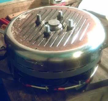
Flat outer face of converter with 'pins' that link to the car wheel:
change drum
to smooth convex bowl shape?
Gears?
The section below was written only days before the first
'successful in
principle' torque
converter test. (It shows my slipping level of confidence after so many
failed converter designs.) I now have no use for gears, but this can
serve as a good indication of all the
troubles the torque converter eliminates.
Given that I still, after
considerable time, have no
working torque converter, I also started thinking about making some
sort of planetary gear setup just to get a car moving, even if only for
a demo. I estimate about a 7 to 1 ratio with an EH motor would get a
car going uphill. That, however would have the motor doing 2000 RPM at
under 30 Km/H.
Something that could actually hit the street could be two
motors, left and right, with 3.5 to 1 gears, which would give as much
start-up torque and allow speeds 55-60 Km/H. Here once again we see the
"oversize" motor (2 motors) needed to gain sufficient torque for
start-up with direct drive, or in this case with a fixed ratio gear. To
allow highway travel we'd need motors on all four wheels at 1.75 to one
- or seven motors (somehow) for direct drive.
Two motors would obviously increase the battery current
requirements to get the car moving as well as doubling the parts, but
it should work. Also the motors would have to effectively be
disconnected from the wheels before the car was to be run on the
highway to prevent over-revving them.
 Two planetary gears
Right: a starter motor with three planetarys, ratio about 4-1/4 to 1.
Left: A car transmission gear with five planetarys. (input gear
missing.)
The 'momentary' starter gear is lubricated with grease, while the
'continuous' transmission gear is sited in a transmission oil bath. To
use these (transmission gears) with an Electric Hubcap, shafts must be
replaced, plates welded on, etc, and how long would the gear last if
not immersed in oil?
Someone once told me a single planetary gear can make a
3-speed transmission, but on looking at one I'm puzzled. I can only see
how it could be 1 to 1, the designed ratio, and "neutral". Unless I'm
missing something, I would go only as far as calling that two-speed.
It's just possible that one might use the designed ratio
and 1 to 1 to get the two-motors car onto the highway. Perhaps with
some sort of centrifugally actuated gearshift. Perhaps also they could
work at different ratios to avoid both hitting weaker performance zones
at the same time, eg 4:1 and 3:1. (Or with 5:1 and 2:1? -- the 2:1
could stay that way at all driving speeds.)
Getting more complex, a single motor might be used with a
three speed transmission, (eg) 7:1 to get the car moving, 3:1 for city
driving speeds, and 2:1 or less for the highway. A question then arises
whether a single 5.5 HP motor has sufficient power for acceptable
performance, with the losses of gear frictions and less than optimum
motor speed and power at various vehicle speeds. These factors will
also up the energy requirements for either a one or two motor system,
increasing the battery capacity needed (...towards that of other
electric vehicles).
But the above was written before the surprisingly strong
push of the "clock escapement" torque converter on the 18th when the
little
weights were added. At this point it will be easier as well as far
superior to get to a practical version of the torque converter than to
attempt to mount car
transmission type planetary gears - which themselves might not last
very long without being in an oil bath. There are now probably fewer
remaining design challenges to work out for the desired advance
on the state of the art than for the "common" solution.
The Torque Machine
At almost the end of the month, I suddenly realized, wow!,
this is actually a new type of 'simple machine' to add
to machines mostly known since antiquity: pulley, lever, inclined
plane, wedge, screw, wheel and axle (presumably including gears), the
more recent hydraulic pistons, and now the mechanical torque
converter machine.
It does follow the usual machine definition: it converts
mechanical energy, ignoring frictional and other losses, from one form
or amount to another form or amount, such that:
FORCEin * DISTANCEin = FORCEout * DISTANCEout (minus any
applicable losses).
The most unusual feature with the torque converter is the
time or velocity factor as related to the force. If the rate is slow,
little force is required to turn
the
rotor and slowly oscillate the masses - FORCEin~='0' and (with small
losses) the output may not move at all. As the RPM speed increases,
FORCEin also increases, exponentially, to cause the masses to oscillate
faster and faster. The work done at the output - which is in fact done
by the oscillating masses - is
still equal to that done at the input (minus losses).
Turquoise Battery Project
Editorial
We have become conditioned to think of batteries as
being either crappy or super expensive, and having limited lifespans.
But there are 1.2 volt Ni-Fe batteries that have been in continuous
service for
decades, a few for almost a century. And I have Ni-MH 1.2 volt "AA"
cells
that I bought in about 1996 when they were first coming on the market
that still work like new. Ni-Mn (2.2 V) holds the
same promise. With the higher voltage and energy of manganese
negatrodes unleashed via a bit of egg albumin, there's much potential
for astounding transformation of key energy systems.
Electrically powered vehicles can perhaps be given enough
storage for a full day's travel with Ni-Mn, to be recharged overnight.
In addition, it seems to me Mn-Mn 1.8 volt batteries could
be made. They'd be "dirt cheap" with only about 1/5 less energy density
and again 'indefinite' life, perhaps for transport but also for
off-grid homes and other applications where weight isn't critical. I
plan to make a MnO2 positrode and try it out - it may even provide more
amps by size.
August
The new electrode compactor was finished on the 4th.
"Recompacting" an electrode that had ended up about 7.5(?) to 8.75(?)mm
thick with the old compactor thinned it down to 7 to 8.3mm, the thinnest dimension being the edges
and the thickest the middle.
That was better compaction, but I was disappointed with
the amount of bulge in the 3/8" top and 1/2" bottom plates. Evidently
even thicker steel is needed! And that compactor took several hours to
make.
Let's see, I could turn the bottom into a 1/2" top,
drilling out the threaded holes to 1/4". That would salvage a top and
sides, and only a new... 3/4"?... bottom would be needed. It already is
a 2-handed carry!
Or maybe I'll just weld another 3/8" or 1/2" piece onto
the bottom. As long as the bolts don't go in more than 1/2", I won't
need to drill and thread it. A 1/2" press piece will do better than the
3/8" one, and it doesn't really matter if the top bulges.
I had hoped better compaction would give lower resistance
readings - it seemed almost inevitable. But in compacting an existing
electrode, dry, it became brittle and fell apart, and any attempt to
push the meter probes firmly in caused each piece to crack. Thus the
megohms readings were unrepresentative.
I wanted to disassemble that electrode and redo it with
nickel plated mesh anyway, and add some monel. Where I had planned to
use it as a negative, I decided it was actually a good positive formula
(60:40 Ni:Mn) and that I'd use less nickel (even very little or none)
and more manganese in the negative. If more conductivity was required
in the negative, evidently copper powder, cheaper and most conductive,
should work, since the copper screen and leed do.
It took a lot of crunching with mortar and pestle to
reduce the clumps to powder again, and it isn't 3/4 the volume of the
unprocessed powder.
Thinking of how sodium silicate "water glass" hardened
even in a closed jar in a ceramic mix got me thinking of the problem of
a good battery electrode binder. It certainly made good ceramic mix
binder! What would it do in a battery? Could it be permanently
solidified by adding calcium (or barium) as my
brother had suggested, to make an electrode solid? Calcium also
had some good
redox potentials for use in a positrode. I decided to try it out.
I took last month's battery apart and put a nickel plated
screen behind the positive electrode. The nickel-brass plate and the
stainless steel mesh were about dissolved and conductivity had dropped
to "not much". The manganese negatrode looked about as it had when I
first made it. I started to charge it again.
Once again it could handle currents up to an amp and more
like when it was new, but those currents dropped off overnight, and the
nickel plating had turned green and dissolved off the copper screen!
That's just not supposed to happen! And we've already seen that copper
screen quickly dissolves without protection.
I phoned Victoria Plating to confirm that the plating was
pure nickel and was told there were "brighteners" in the solution that
would end up in the plating. "We're a decorative plating shop" he said.
SO! The quest for real, pure nickel or nickel plated materials, as
required for alkaline positrodes, has been thwarted again,
unexpectedly, from
a hidden cause! I'm getting really, really sick of dissolving screens
and leed wires. How can a whole new battery technology founder on
something so seemingly trivial, whose solution is well known?
Perhaps a whole new idea is needed? Graphite powder has
been used to improve the conductivity of nickel electrodes. Presumably
then it's a rare conductive material that doesn't degrade and remains
solid in the charging positrode? It's about the most stable form of
carbon. So: what about a solid (non-porous) graphite collector sheet
instead of a metal one? One with a plate or screen of metal behind it -
or embedded in it - connected to the terminal but out of the
electrolyte? Graphite has electrical resistance, but it would only be
across the thickness, over the entire plate area - not much overall. As
long as the electrode material was well pressed against it, it should
work.
And rather than trying to find ready-made graphite sheets
or plates, I could just buy graphite powder, add just the right amount
of sodium silicate/barium/calcium "glue" (rendering it non-porous yet
still conductive, I trust - or some other technique to accomplish that
if this doesn't work), and press graphite/metal mesh sheets the same
way as electrodes. (Hmm... I wonder what heating the product in the
kiln might do?) On checking, I find graphite powder is readily
available at art stores, about 30-40 $/pound retail in small quantities.
Suddenly this seems like much the best plan!
In fact, some cheap metal will do for the screen or plate,
so it replaces the pricey "unobtainium" nickel or nickel plating with
cheap, readily available graphite. The only remaining nickel in the
battery could be the monel powder (which I hope can be retained - we'll
see) and the active nickel hydroxide.
Graphite Collector Sheet Experiments
Obviously the next task was to try making a graphite
collector sheet or plate, since I seem to have most of the other things
working reasonably well except for that worrysome self discharge -
which may itself be a symptom of corroding collector plate.
I bought some graphite powder at Opus art supply, mixed in
a little sodium silicate and barium sulfate (a few percent), and tried
to make a sheet. The powder looked much the same as several black
powders I've been using. The sheet turned out too thin, and very
brittle, and with plastic underneath it curled into and arc shape as it
dried. But the resistance measured only ones of ohms - great!
Okay - four teaspoons of graphite instead of two, more
wetted with sodium silicate. (Maybe I should measure these things?)
That made a sheet I consider to be about the right thickness, a little
harder and reading about 10-20 ohms.
Also, I found www.GraphiteStore.com on line and
decided I'd hedge my bets and order a few ready-made "flexible"
graphite sheets, .06" thick and .12".
These turned out to be 'natural', 'expanded' graphite,
'99% pure'. They had the desired low electrical resistance typical of
graphite. I expected dense, black, brittle, smudgy stuff, but they were
very light, silvery, could flex some, and weren't smudgy at all. In
appearance, they could almost have been some dull metal, though they
dented and scratched easily. The light weight will subtract almost
nothing from the "energy density by weight" specs.
I'm pretty sure this is 'the right stuff', ideal unless
something
in the 1% impurity proves to be a problem, which it didn't immediately
seem to be on
trying it out. The remaining problem will be making a seal to have the
electrolyte
stop at the graphite so that the metal mesh or whatever behind it, and
the leed, going to the "+" terminal, doesn't corrode away.
When I tried one of the sheets out, on the night of the
21st with the manganese electrode (still not in bad shape except for a
couple of small broken chunks) and a remaining chunk of nickel
electrode that I peeled the rotting stainless steel mesh off of (only
about 2-3 square inches - the whole electrode was breaking into
pieces),
it quickly charged to a higher voltage than
before. It was soon 2.66 volts on 100 mA charge, and started dropping
from about 2.2 volts (later 2.3) when the charge was disconnected
instead of from
about 1.95, closer to my original rough voltage estimate of +1.0:-1.36
= 2.36
volts for Ni-Mn in neutral salt electrolyte.
Seeing that, I checked the pH of the fresh electrolyte.
The electrolyte had originally been
turning alkaline around 12 or 13, and it was now in fact neutral -
7 or 8. Although the original mix was
Mn powder and MnO2 powder, not Mn(OH)2, I had added Ni(OH)2 to the mix
to derive nanocrystalline conductive nickel metal from, and this would
have charged first, releasing the OH-'s that quickly alkalized the
original solution.
I may mention the possibility also
that in neutral pH with salt, it may discharge from Mn to MnO rather
than Mn(OH)2, and the positrode from
NiO2 to NiO rather than Ni(OH)2,
and the pH will remain neutral. With the KCl salt electrolyte, the O--
ions might be carried on the chlorine as potassium hypochlorite, KClO.
I could be
wrong.
(In fact, the electrolyte hypochlorite ion idea seems suspicious.)
But this would have interesting implications if it's true.
It could also mean (a)
that nickel oxide would be the 'correct' form of nickel to buy rather
than nickel hydroxide and (b) the Mn negatrode would also work with a
chelated lanthanum perchlorate/chloride positrode, which also moves
oxygen ions. ...which would mean nickel electrodes in any form are
entirely unneeded, and super high energy densities would be attained.
However, I could be wrong and the presence of water even at neutral pH
will result in hydroxides on discharge rather than oxides. Really
though, this works and looks like a fantastic battery either way. It's
better than
the best and will put electric drives on the road - and for the moment,
that's all I really care about!
The next morning (22nd) the battery, though charged
overnight, wasn't holding its
voltage as well as it was at first, and
was taken apart and cleaned, the electrolyte being replaced. There's
still something causing self discharge. I suspect the monel, and I'll
try an electrode with graphite powder instead.
On inspection the silvery graphite sheet seemed unchanged.
A
slight discoloration where the electrode had been in contact readily
washed off and it proved to be unblemished - it wasn't possible to see
where the electrode had been. (...except the expanded graphite's
surface was so soft there were
indents from the scrub bush used. Brushing another area left it with
exactly the same appearance.)
By evening the voltages were marginally better
yet, dropping from around 2.3 volts (and somewhat more slowly), around
20% improvement over the original alkaline 1.9 volt levels. I had a
similar improvement when I used the commercial Ni-Cd electrodes with
salt electrolyte: from 1.32 to 1.6 volts or so. (Wow... 2.3 volts open
circuit! - perhaps 2.1 volts
nominal, 1.75 times the usual 1.2 volts!)
It would seem at least some of the awful self discharge
I've been
seeing all along throughout all my experiments was indeed from
corroding positrode metal, and that the graphite collector sheet has
improved the problem.
This battery with the chunk of electrode supplied 12 to 9
mA (gradually dropping) into a 100 ohm load for an hour and a half, and
then recovered to 1.2 volts. Since the open circuit voltage started at
about 1.7 volts, 1.2 / 1.7 = .5 V drop, so the internal resistance of
the battery was about 42 ohms, which is definitely not as good as x1's
of milliohms or less. This points to the need for better conductivity
within the electrodes. I ran this a few more times, drawing a load for
an hour or more once or twice a day, and the figures gradually
improved, running up to 17mA (with 100 ohms = 1.7 volts) which dropped
to 14 in a few minutes and
then gradually to 10 in an hour, to 8 in a couple of hours. (Even
without a load, the self discharge brings it down to about 1.2 volts in
an hour, 1.1 volts in two hours, and 1.0 volts in three. Obviously this
is by no means satisfactory.)
Graphite Powder - Carbon Fiber
Graphite powder should greatly increase the
conductivity of the electrode, and the heavy monel powder could be
eliminated or reduced. Fine, short bits of carbon (graphite) fiber
might be even better, or both together.
Again, when I first put the chunk of electrode to the
graphite
sheet, it was (for once) dry, and I measured the conductivity. The
resistance was in the "x 100 K Ω" range. As long as its not an
insulator it should charge, but that's not exactly fab conductivity.
Hmm... I did add cobalt powder and monel to that
electrode. I think I should also try adding graphite powder - or
using it instead - to help it to conduct better. In fact, perhaps the
remaining self discharge would be eliminated if I eliminated the last
copper and nickel bearing metal from the positrode. (Monel will
doubtless still
work fine in the negatrode if it also proves to have low conductivity
and needs it. Monel or nickel might also work fine in a lower voltage
positrode, eg Mn - the voltage might be too low to corrode it.)
On the 23rd I had the idea to try carbon (graphite) fiber
rather than, or in addition to, plain powder. The idea is to improve
conductivity, and electrons can doubtless pass along fibers more easily
than between doubtfully connecting powder granules. If, in an ultimate
example, very fine closely spaced fibers, "nanorods", all ran like the
bristles of a brush in parallel from the font surface of the electrode
to the graphite backing sheet, the whole electrode would have
"ultimate" "short circuit" conductivity. Some university can figure out
how to accomplish that later. Random fibers in the electrode mix would
be the next best thing. Carbon is much less dense than monel, so the
energy density by weight would be improved, and the "crackly
microphone" effect Edison got from graphite powder in his electrodes
would surely be eliminated with fiber.
Suddenly - and at last - I think I can see obtaining the
sort of amps needed to start a car engine or run high power electric
motors efficiently with very small batteries!
I tried cutting carbon (graphite) fiber into short bits to
help
improve electrode conductivity on the 29th. However, it bunched up and
didn't mix into
the electrode powder well, and dust came off it, mostly while cutting.
It was like
working with fiberglass or asbestos and I was soon feeling itchy needle
pricks just from the little bit I did - yuk! I'll stick with the plain
graphite powder in the electrode mix, I think, and a graphite fiber mat
- with minimal cutting - as
the closest thing to an inner metal mesh that's available.
Or I could try buying pre-chopped fibers, which come as short as 2 or
3mm lengths. That should be easier to deal with if it doesn't clump up
during mixing.
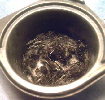 Chopped carbon (graphite) fibers, much finer than human hairs - and
dusty.
Chopped carbon (graphite) fibers, much finer than human hairs - and
dusty.
Egg Layer - hard electrode shells?
If one were to smear or paint egg white all over the
electrode, some would wick in but much would dry on the surface. If the
surface was
then torched, it would be left with a "caramelized" hard but
microporous surface layer, to prevent the molecular changes that occur
with
charging and discharging from occurring right at the separator. That
sort of surface "casing", keeping the reactions and "stuff"
inside, might make the battery last far longer - virtually
indefinitely. One could look at it as a simple and in many ways
superior replacement for the metal electrode housings of the pocket
battery.
I tried this on one face of the little crumbling piece of
Ni
electrode, though
not a very thorough coating. I didn't do the edges, and it seems to
work, or at least not to do anything bad, whereas it continued
disintegrating around the edges. The next thing will be to try
"painting"
and "caramelizing" a whole Ni electrode, and then see if it gradually
crumbles in use like the last one or stays in one healthy piece.
Manganese-Manganese: DIRT CHEAP High Energy Batteries
As well as being the new negatrode material, MnO2 is of
course the positrode chemical in both standard and alkaline
non-rechargeable batteries. In neutral KCl solution the reaction might
be:
2 MnO2 + H2O + 2 e- <==> Mn2O3 + 2 OH- [+.5 v],
or it may take the same form as in alkaline solution, except with the
.5 volt figure applying rather than the alkali +.15 volts:
MnO2 + H2O + e- <==> MnOOH + OH- [+.5 v]).
Whichever variant applies, it seems certain one could make
a Mn-Mn/KCl battery. It would be .5 volts less than the Ni-Mn/KCl
battery, about 1.8 v open circuit, but otherwise similar. It would
probably have similar almost indefinite lifespan. The lower voltage,
but with slight compensation for it making a lighter electrode, would
mean about 1/5 less energy density. (Hmm, actually, that's better than
I was thinking. ...and still higher than lithium types!)
A bit lower voltage and energy... what's the advantage?:
Low, low cost!
The nickel, as oxide or hydroxide, is the main cost of
Ni-Mn. The Mn-Mn battery would be "dirt cheap" - similar to all those
dry cells that are used once and thrown away!
For transportation, higher energy density is worth a
certain premium (though I don't mean the sort of absurd "premiums"
being paid for lithiums), but for stationary applications like off-grid
homes very low cost means one can afford sufficient battery reserve to
store oodles of energy when the sun, wind, waves or tide is providing
it, for the times when it isn't. Or a generator could be run
intermittently to charge the batteries rather than running full time.
On the water where weight is less of an issue than on land, boats and
other vessels could probably employ Mn-Mn to advantage for their
electric propulsion. (That could be combined with wave, wind or solar
power to recharge whenever conditions were good.)
The more I consider it, the more other potential
advantages I see, too:
* manganese positrodes might be more conductive and so provide higher
maximum amps than nickel. (In fact, the thinner electrode - see next -
is bound to be more conductive both to electrolyte ions and to
electrons.) That provides superior power even for electric transport,
and faster charging.
* The nickel electrode has a lot of manganese already added to it to
allow the nickel to charge to a higher valence - a considerable portion
of the manganese needed for a Mn electrode is already there. Without
trying to work out exact proportions, assuming MnO2 only changes by one
valence state (to MnOOH), twice as much MnO2 is needed in the positrode
as in the negatrode, which changes two states (Mn -> Mn(OH)2).
My sense says that the denser MnO2 electrode will be much
thinner than the fluffy Ni(OH)2 one - half - allowing the whole battery
to be almost 1/3 thinner. This saves on all materials except the
negatrode, saving weight and space - probably enough to compensate for
the higher voltage of nickel. It seems likely that in spite of needing
a few extra cells because of the lower voltage, eg about 21 cells for
36 volts instead of 16, the energy density might not be lower than with
nickel after all!
* The lower voltage might allow use of the most conductive
conductivity additives such as monel and nickel, which probably don't
corrode below a threshold voltage (about 1 volt), again raising
potential current capacity and reducing charging times.
* The same substance is in both electrodes should the ("green")
ingredients be deemed worth recycling. And it's one less chemical to
stock.
* The Mn positrode is more "old hat" with no(?) recent developments, so
there would be little for vested interests to bite on to attempt to
prevent manufacture by patent challenge.
* The low voltage would have no problems with oxygen overvoltage during
charging.
Wow! Considering all this, it may well be that it's not
worth bothering with Ni-Mn and I should switch entirely to Mn-Mn! But I
am now beginning to trespass on September.
Next Battery(?)
For the "production" battery, I wish to make bipolar cells
that can simply be stacked together to obtain the desired voltage,
almost as I had originally planned except this time these will be
individually
separate, like a giant version of stacked "button cells" used to make
small higher voltage batteries. They will then be stacked into an
appropriate case that is
then sealed and holds under pressure - the giant buttons themselves
aren't expected to hold against pressure.
The battery cross section:
- End wall with flat-head terminal bolt sticking through the middle,
tapered hole. This must seal. Red plastic ring around bolt identifies
"+".
- Sheet metal or mesh collector sheet, soldered to the bolt and against
the wall.
- "n" stacked bipolar cells to obtain desired voltage, eg 36 V.
(details below).
- Sheet metal or mesh collector sheet, soldered to hex head bolt.
- Sponge piece. This should compress to about the thickness of the bolt
head. It holds all the cells and connections pressed together.
- Far end wall. This is assembled last, and is preferably gasketed and
bolted or screwed on rather than glued, making it is easy to replace
individual defective or weak cells.
- A nut holds "-" terminal bolt tight against wall for seal. Black
plastic ring identifies "-".
Cross section of each cell:
- expanded graphite sheet (positive connection)
- a painted layer of calcium carbonate on the inside of the graphite
- the active positrode briquette (details below)
- carbonized egg white layer - painted on electrode, dried, and then
torched (also on edges)
- microporous cellophane sheet
- separator paper
- the active negatrode briquette
- copper or stainless steel screen
- nickel-brass sheet.
These cell assemblies, 3" x 6" (20 amp-hours)
or 3" x 9" (30 A-H) by about 8 mm thick, will be sealed around the
edges by dipping them in some sort of slightly flexible paint or RTV
cement.
This seal is not expected to be perfect or to hold pressure: that's the
job of the sealed case that the cells are mounted within. It is also
the job of the chemical additives to convert hydrogen and oxygen gasses
generated back into water to keep the pressures low.
Before I do this full size, I'll think I'll try one in a 1.5" x 3"
format - 1/4 of the 3" x 6" size and only about 5 amp-hours. Since each
cell is to be edge sealed, I want a close fit. I think melt-forming
round pipe is out. I wish I could find a source for square pipe with
sharp corners.
Why haven't I made it yet? There's only 44,640 minutes in a month, and
many things to do! I did find time to make inserts for the new
electrode compactor for making 1.5" x 3" electrode briquettes.
Positrode
I planned the next positrode mix as follows:
* Collector sheet of expanded graphite.
* A piece of carbon fiber mat for a "grill"/"mesh".
* A coating of CaCO4, calcium carbonate, on the electrode side of the
graphite.
* NiO - 60 wt%
* MnO2 - 40 wt%
* Graphite powder or chopped fibers - TBA wt% (of above)
* Sb4O6 - 1 wt% (of Ni+Mn)
* Co2O3 - 1 wt% (of Ni+Mn)
* NaSiO2 - 2 wt% -- best "glue"?
Negatrode
For the negative side:
* Nickel-brass collector sheet
* Copper mesh
* MnO2 - 97 wt%
* Egg white - 0.1 wt%
* NaSiO2 - 2 wt%
* Sb4O6 - 1 wt%
This is to be "pre-charged" in a tank of KCl (or NaCl - cheaper).
Bolt-Box Electrode Compactor Mark II
I considered that 9 or 10 inches tall would be a good
height for batteries placed somewhere in a car, eg in the trunk, and
that 6 inches seemed a useless size limit, so I
made the new compactor for 3" x 9" electrodes instead of 3" x 6". If
desired, a spacer(s) can be inserted to make smaller electrodes with
smaller press plates, but none bigger than the whole compactor are
possible. I made pieces for the original size with the original 3" x 6"
punch plate.
Parts List:
Bottom: 1" x 4" steel bar, 12" long. [1]
Sides: 0.5" x 0.5" steel
bar
1 @ 12" long[2]
1 @ 10: long
2 @ 3.0" long[3]
(or one piece about 28.5" long to cut the above from)
Top: 0.5" x 4" steel bar (3/8" x 4"), 10" long.
Press Plate: 0.5" x 3.0" steel bar, 9.0" long.[4]
Bolts: 38 - 1/4"-20 x 1.5" hex head. (-20 = 20 Threads Per Inch.)
38 washers might
also be nice. I haven't been using washers so far.
7 - #8-32
x 3/4" flat head ("machine screws")
Notes:
[1] A 0.25" or even 0.5" thick
plate bulges considerably, making rounded, poorly compacted electrodes.
0.75" might be enough. I used a 1/2" piece, then after trying it I
decided I should weld another 3/8" piece onto the bottom to strengthen
it - total
7/8". For 9" long electrodes, the length of the box is 10". A 11.5" or
12" base length provides space on each side to clamp the box to the
worktable with C-clamps, which is necessary. (Mine, at 11.375", could
stand to be a little longer.)
[2] The extra 2" of length allows a holding bolt at each end "outside
the box". When one flat-head bolt is removed, and one end piece (having
one flat-head bolt) is removed, the side can be swung open to easily
remove the finished electrode.
[3] The press plate needs to
press flat
all the way across, and there should be virtually no side or end slack.
Maybe allow a few mils to fit a sheet of thin plastic.
I had to grind slightly rounded edges off my first press piece and the
compaction area ended up about 2.9" wide instead of 3.0". The 3" end
pieces were ground down to 2.9" to fit that before the bolt holes were
drilled.
[4] I think this is thick enough. If the
electrode isn't quite flat, switch to 1/2"... and probably to 1.5" long
bolts. Also a 1/2" plate will press all the way to the bottom without a
spacer for thin electrodes.
Also:
1/4", 20 TPI threading tap
7/16" hex socket (=11mm) for powerful, variable speed electric drill to
do up bolts
Any spacers and smaller press plates desired for making smaller
electrodes.
Variations:
Naturally I'm only going to make one (more) compactor. There are more
things that could be tried out, some mutually exclusive:
- fine thread 1/4" bolts instead of coarse (20 TPI), or other size
bolts entirely.
- Other bolt head types besides hex, eg socket heads.
State of Nickel
I don't understand why nickel sulfate or nitrate is used
to make nickel hydroxide. If you just put nanocrystalline nickel oxide,
NiO, into the
positrode and charge the cell, when the OH- ion comes from the
negative, would it not attach itself to the nickel oxide to make nickel
oxyhydroxide, the same product as the regular charging reaction except
no water byproduct?
NiOHOH + OH- <==> NiOOH + H2O + e-
NiO + OH- <==> NiOOH + e-
The nickel oxyhydroxide would then discharge to
nickel hydroxide like usual, gaining HOH in the overall process, which
could
easily be made up or allowed for with extra water initially.
Nickel oxide is a very fine black powder. I don't understand why it
isn't used, so I bought some to try out. Since it's sold over the
counter at pottery supplies, it's much more accessible than nickel
hydroxide, to purchase which I had to import it in a 10 Kg pail
(minimum order), provide a company name for, and sign something.
The Price?
The nickel is the most costly main ingredient in the
battery, but even at $18 retail for just 113 grams of NiO (higher
quantity would be somewhat better price - wholesale would be better
yet), it worked out to 560 $/KWH:
18$ / .113 Kg = 160 $/Kg (...that's surely WAY over the wholesale price
- Pure lanthanum rare earth metal ingots are less!)
[98 (weight of Ni(OH)2) / 72 (weight of NiO)] * 420 AH/Kg (for Ni(OH)2
with MnO2) = 572 AH/Kg.
572 AH/Kg * 0.5 volts = 286 WH/Kg
160$/Kg / 286 WH/Kg = 560 $/KWH.
However, the nickel is only 1/2 of the of the battery.
Manganese oxide is 1/3 that price. Of course, that
doesn't account for other materials or the cost of manufacture, but
it's also for small quantities of the active chemicals at retail price.
Ballpark, I think these batteries should cost somewhere around the same
price
per effective kilowatt-hour as lead-acid batteries, with effectively
1/5th the
weight and size and at least 10 times the longevity.
Without going into details, logically it follows that Mn-Mn batteries
should cost considerably less than lead-acid.
http://www.TurquoiseEnergy.com
Victoria BC