Turquoise Energy Newsletter #32
Turquoise Energy Ltd. News #32
Victoria BC
Copyright 2010 Craig Carmichael - October 1st 2010
http://www.TurquoiseEnergy.com
http://www.ElectricHubcap.com

Contents/Highlights:

September in Brief (summary)

Electric Hubcap Motors, Motor Building Workshops - Motor & Controller Availability
  * Motors: workshop/product version finalizations: axle, plates/rotors, hubs (turning and welding), seals...
  * Customers for ready made EH motors & controllers may help fund workshops.

Torque Converter Project
  * Better Layouts
  * Single "full circle" escapement to maximize forces?
  * Heavier drum makes little difference?
  * Too many ideas, too little time, delay next step

Wave Power Project
  * My float assembly design (and perhaps the mechanical transmission) still has advantages over others
  * Yet another rant about dysfunctional government
  * Remake of transmission with one-way ratchet, lawn mower motor as generator
  * Low Voltages force change from V-belt (1:5) to starter & flywheel gears (1:20 - better but still low V)

Pulsejet Steel Plate Cutter Project
  * Theory - Designs
  * On hold for now (making motors with brake rotors for now - no steel cutting needed).

Electric Outboard Motor Project?
  * The prototype motor, about 2 HP if run at 24 volts - comparison with 2 HP induction motor outboard?
  * Splined axle assembly?
  * Searching for an outboard leg, 5-10 HP

Turquoise Battery Project
  * Using the Spot Welder
  * Energy Densities Visual: Mn-Mn batteries lost in the vastness of an old electric drill Ni-Cd battery pack
  * Mn-Mn: ultimate dirt cheap, long life, high energy density dry cell battery?
  * Electrode Briquette Binder Technique - how a popular technique works. (Duh!)
  * Charging to permanganate, valence 7
  * Carbon/Graphite and Positrode Connections - making solid, low resistance carbon sheets
  * Permanganate
  * Antimony catalyst
  * Borohydride Chelating Agent


Newsletters Index/Highlights:
http://www.TurquoiseEnergy.com/TENewslettersIndex.html

Construction Manuals for making your own:

* Electric Hubcap Motor
(latest rev. 2010/02/xx)
   - the only 5+ HP motor that can easily be made at home?
* Turquoise Motor Controller
(latest rev. 2010/05/31)
   - for the Electric Hubcap. (Probably there are commercial controllers that would work, too.)
* 36 Volt Electric Fan-Heater
   - if you're running your car on electricity, you'll want a way to defog the windshield and keep warm.
* Lead-acid batteries: Sodium Sulfate 4x longevity additive - "worn out" battery renewal.
* Simple Spot Welder for battery tabs, connections (in TE News #30)

all at: 
http://www.TurquoiseEnergy.com/


September in Brief

   I spent considerable time developing a finalized mechanical design for the Electric Hubcap motors to be built in the workshops. I cleaned up accumulated clutter from the shop, put down linoleum, and made a new workbench for a more pleasant and functional working environment. And I wrote up a brochure to advertise the workshops.


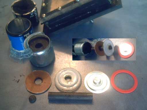
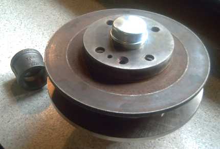
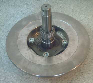
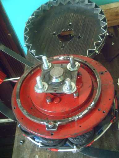
"Production" EH wheel motor mechanics layout.
1-1/2" cast steel pipe couplings machined into bearing hubs and welded to '6129' disk brake rotors,
on independently rotating (for torque converter output rotor) dexter trailer axle.

   I also cleaned the woodstove chimney and reroofed the back porch roof and a side roof of the house -- all long overdue. The porch roof yielded an immediate benefit: I could safely weld motor hubs under it in the rain the next day. I had also hoped to continue renoing the dilapidated upstairs bathroom, which I started in June and then left sitting, for anyone who might come to the motor workshops from out of town and want accommodation. Oh well, next month. (Say, with the roof fixed, I can safely repaint!)

   Though I thought the 'clock escapement' torque converter would move the car with more weight of escapements added, and I came up with a number of possible options, I finally became hesitant to proceed owing to the loud noise - a din that was a lot more than a "tick-tock" - thinking there just had to be a quieter way... but the above necessary activities ate most of the time I would otherwise have had to look at it. Perhaps a bigger diameter yet and more closely fitting parts will make a considerable difference.

   One can't help but wonder, does Canada care so little for its future that even its most accomplished inventors, working on developing products to help the nation achieve its own stated energy goals, should be left penniless, to do things like roofing for themselves? Most talented, enterprising people live well above the poverty level and would be able to call in tradesmen, as I did when I was employed doing electronic equipment maintenance and repairs. Inventors working for civilization's future get the cold shoulder wherever they turn for money (tax credits for a percentage of R & D money already spent excepted). It was tempting to take up my neighbor's offer to reroof his house for money and put off the energy projects for a while. But what would become of the developing means for turning North America's cars into plug-in hybrids, and to what look like the best imaginable battery chemistries and designs, if I fell off a roof? Or for that matter, as the projects drag on with only one person doing everything, suffered ill health or simply wandered off and quit putting my time and energy into things of no immediate practical benefit to me?

   In studying cheap manganese as a positive (as well as a high voltage negative) electrode material, I noted on its electrochemical reactions charts that in salt solution the positrode should have twice the amp-hours it has in alkaline solutions and also as shown in 'textbook' descriptions of battery reactions. This would make the cell 33% higher energy density. It already looked probably better than nickel, and suddenly I visualized a new realm where cars and perhaps clean, quiet transit buses, trucks and trains could drive a full day on one charge, where light electric aircraft might be feasible (even with Electric Hubcap motors & mechanical torque converters?), and where living off-grid with an intermittent power source such as sun, wind, waves or tide becomes much more practical, per this expanded chart:


Manganese keeps looking more and more promising - for both electrodes.
I made this chart assuming valence change would be between 4 and 2
in the positive electrode, in salt solution electrolyte, a 33% energy 'bonus' over alkali.

   But even that wasn't the end. On making a battery, the voltage was higher than expected (2.2 vs 1.8), and the manganese chart shows that it could move up to five electrons at about +.9 volts going between valences 7 and 2, the test battery size yielding up to 17 AH instead of 5 with Ni-Mn. As far as materials go, such batteries would cost considerably less than lead-acid per watt-hour, and would have about 14 times the effective energy density. Imagine one car battery replacing 14! It may prove necessary to add nickel and make a 'mixed valence' electrode to prevent migration of soluble permanganate ions, but a thinner electrode with much less nickel, and it would still be much better than anything currently available, and relatively economical.
   I still don't have usable batteries, but the problems are being gradually sorted out. Worst feature now seems to be high internal resistances, 5-10 ohms, using ready-made graphite sheets, which will degrade. It would appear that a complex but necessary step may be to produce flat sheets of highly conductive carbon of composition similar to the carbon electrode rods used in dry cells, since all metals appear to oxidize away in the positive electrode.

   On consideration, I think my double wave energy capture float has a good advantage over the single float unit being done in Denmark and other units, and should be tried. It works as the slope of the water's surface changes rather than the height. And I don't know what other units have for transmissions - I suspect my mechanical transmission with arms would be more efficient than hydraulic types, as used for example in Pelamis.
   In the last few days of the month I got tired of house repairs, confusing and conflicting torque converter design options, and ucky black graphite powder and road tar, and I put together a new transmission for wave power from some of the original parts plus those made or acquired last spring.
   The unit should have two ratchets, up and down for up and down wave slopes, but I think I'll see what happens with one for the falling slopes first - a test may suggest using a shorter arm (smaller wrench) or other change.
   I hope to try it at water's edge in October, weather permitting --- which in this case means strong winds from the right direction to make waves at a boat ramp: SE (Cattle Point) or SW (James Bay).


Electric Hubcap Motor Building & Workshops

Getting Ready

   I wanted to have "cut and dried" parts and procedures set up for doing workshops. The least defined part of the operation was the mechanics. Sure, you can take various old disk brake rotors, hubs and bearings and make a motor that runs great, but having a motor and a torque converter turning at different speeds on the same shaft complicates matters considerably, and I really needed to be able to say "Use this, and this, do this and make this", with the parts and procedural details worked out in advance. Essentially, I had to develop and build another motor, or at least its mechanical frame, in what I planned would be its "final" initial production form.

   I first thought of cutting or having cut some custom shape 3/8" thick steel plate pieces for the motor rotors and stators. Then one day I noticed that the 1-1/2" threaded pipe coupling piece I'd found to use for a hub with trailer bearings could be fitted onto the 6129r disk brake rotor that I'd thought looked like the best off-the-shelf part for both stator and rotor. (The other rotors I'd tried seemed to have bigger center holes that would let the pipe fitting fall right through.)
   That simplified things: no CNC cutting, no pulsejet, waterjet or other major steel plate cutting. Ready to go rotors; just some holes to drill. (and one face that should ideally probably be turned down to flatten a wider band to glue magnets to.) So I got more of the pipe fittings (just $2.40 each for center bearing hubs!) and turned two on the lathe to fit right and with a tenon at each end for the bearing races. And I turned down one rotor face for the magnets. That left it just 5/16" thick. The magnetism will be coming through it. Oh well, it's lighter that way!
   They seemed to fit very well and run close enough to "true", so I welded the hubs to the rotors and bought more 1" I.D. bearings with races. Trailer axles with flanges still seem like the best axles, even if it proves necessary to turn down a bit of additional length. The first welds came apart. I asked the guy next door and he said I was using too little heat and too small of welding rods, and that I should weld to the rotor first because it was thicker steel. The next welds were better but still broke when hammered. Some of the breaks were actually of the coarse cast steel rather than the weld itself. I turned the welder to max and tried again. I've never been able to weld except with the skinniest rods. It worked, but to put down lots of metal sure sucked the rods up fast! This time most of the welds held when the unit was pounded with a hammer (one cracked - redid it). So, welding them works, but takes some practice. (Or someone who can actually weld.)
   Unfortunately, while I can easily turn the hubs, and the raw rotors also - just barely - fit onto the lathe, I can't fit them on after they're welded together, which would be the ideal way to ensure everything runs true and centered. (Perhaps I could make some sort of custom lathe hub? I'd have to learn how to cut threads with the lathe. Ugh!)

   Made and assembled, there's the mechanics of a motor, and weighing just 8.3 Kg/18 pounds. The finished bare motor should be only about 31-33 pounds! All it needs then is the torque converter pieces... and a working model torque converter.

   I went to Thomcat Trailers to buy more bearings, and was reminded there that if they aren't sealed, road dirt will get in and make short work of them. I had managed to blissfully put this detail out of my mind while I was working on getting things working, but now I had to come up with some unusual configurations of seals. The middle one between the two hubs will be unusual, and a one turning rotor configuration will need a very tall outer cap.
   Another good point was that you could drill a hole though the axle with side holes near where the bearings go, put a grease nipple on the end of it, and squeeze in grease to the bearings. That and probably greasing the torque converter parts would pretty much take the place of oil changes. But it would make it easy and tempting to overgrease.

   The price for the 1-1/16" trailer stub axle with flange had gone up from $25 to $33, and I also found to my dismay that, as at Canadian Tire, the bearings for 1-1/16" shafts were now almost twice the price of those for 1" shafts, $8.xx instead of $4.xx, notwithstanding that they are identical except for a slightly fatter inner piece on the 1" type to reduce the diameter a bit more. As each motor (configured for torque converter) needs four, I'll be looking for 1" trailer axles, or a substantially better deal somewhere on 1-1/16" bearings. Only the 1-1/2" steel pipe couplings for the hubs are cheap, and they have to be machined and welded.
   This takes the price just for axle and fittings from around $75 two years ago to over $100. Brake rotor disks have also gone up, and so has copper wire and doubtless other supplies. I'll certainly be doing some shopping around when I order parts for several motors.

   Which brings me to motor configurations. The motor can be made with:
1. Rotating axle - rotor bolted to axle flange, stator on bearings.
2. Stationary axle - stator bolted to axle flange, rotor on bearings.
  These are in fact identical except the rotor and stator are reversed.
  There are two sub-versions:
    a. rotor (stator) welded to machined pipe-coupling bearing hub
    b. rotor (stator) bolted to standard trailer wheel bearing hub
        (eliminates the welding and potentially the lathe turning work, and can be reversed).
3. Mechanical torque converter (MTC) ready.
4. Custom axles (eg, see "outboard motor project" below)

   In the MTC version, the axle rotates independently of both the stator and the rotor, turning with the torque converter output drum. With two independently rotating units on one axle, the trailer wheel hub option is impractical and both units are welded to the pipe-coupling hubs.


Configuration 3, for MTC. Flange at bottom. To left, the pipe-coupling hub.

   Note that the MTC version (with the great manganese-salt batteries) could also be good for electric aircraft. Like the car wheel, it's usually desirable that the propeller turn more slowly than the motor. I'm not sure how large a plane one motor and MTC of this size could power, but it would replace a considerably larger gasoline engine. (Then there's two motors & props, or multiple motors on one longer axle - there's a light electric aircraft in here somewhere.)

   Having welded hubs onto both my rotors, I needed another, unmodified, to take a photo of configurations 1 and 2 for the motor making manual. Having found a list of cars using the '6129' rotor, I found the Gren version at Canadian Tire for just $20 retail, making it among the cheapest as well as the lightest and simplest of disk brake rotors. Now if it weren't for that nasty axle and bearings, it would be really economical.


Config 1 or 2: one spinning rotor (inner bearing for it shown), one bolted to axle flange.


Mechanical Torque Converter (MTC) Project

   Gears and most mechanical torque converters have their speeds referenced to 'zero'. That is, in a gear system, the axles that the gears turn on don't themselves turn, and the faster the speed, the faster the gears turn on those axles. And in other mechanical torque converters, the oscillations are likewise referenced to speed zero, so the faster the speed of the engine or motor, the faster the masses oscillate.
   All along I've implicitly been trying to construct a converter where the masses oscillate relative to the difference in speed between the input and the output RPMs. That way, the masses are oscillating no faster on the highway than at low speed. In that manner, I hope to keep losses and the attendant heat and wear to a minimum, especially to ensure the that the system doesn't need to operate in an oil bath like most automotive transmissions. The oil bath introduces large losses from fluid frictions.
   My implicit 'relative motions' requirement has been a considerable part of the design challenge. The conceptions are easier with connections to a zero reference and workable designs are much easier to come up with.
   I came up with several modified 'clock escapement' ideas (below), but I didn't have much time to work on any of them.

A better Layout?

   Before even finishing the second set of three escapements to see how it worked, I was refining the design in my head.
   If I made a new fanfold gear with the double 45º folds leaving a flat outer face against the outer rim, the inner diameter would probably increase enough to raise the number of teeth from 25 to 27, being divisible by 3 now being seen as a target, with about the same spacing.
   Then, instead of six escapements spaced around the rim, I'd have just three with arms twice as long, each spanning 8 teeth and occupying almost 120º of space, with the weights at the ends. These long "pendulums" will place the same mass farther from the pivot point for increased inertial moment.
   Then the mass of the escapements would be made to be whatever it takes to get good propulsion. Hopefully that will be a lower mass than would dent the gear teeth. There is also enough height to the unit to put three more arms above the first three if necessary, offset by 60º, ie, pivoting from the gaps between the lower three. But I expected and hoped that wouldn't be necessary.

   It occurs to me the best way to reduce the impact on the teeth isn't simply to use thicker aluminum for the escapements, it's to put in inch long wedges of aluminum for the points, to strike along the whole 1" height of the tooth at once. That should spread out the momentary sharp forces to low levels at any given point.

   Having made 5 escapements for the first unit with the 25 tooth gear, I thought I'd make the last one with long arms and try running it with that and four of the short ones - the two fatter new ones and two of the three old thin ones. I was pretty sure the car will move reasonably well.
   But before I even got started on that, I looked again at clock escapements on the web and at escapements where the two points hit the sprocket gear 180º apart. Applied to my design, as one point hits the peak of its tooth, the other would hit the trough between two teeth, and as one is climbing one "wall" of its tooth, the other is descending the other wall of its. This arrangement would mean the points and valleys must be symmetrical. It would also impart the maximum sudden impulse to the oscillating masses. It would also seem best if the points were at opposite sides of the wheel to provide the maximum force leverage. That would mean just one heavier escapement... with any odd number of teeth, so 25 would be fine... or at most two escapements.
   On checking with the actual gear, I noted that 1/3 of the valleys had bolt heads sticking out a bit. Okay... wedges filed flat around the middle to miss the bolt heads?
   On consideration, I realized that to make it heavy enough and stiff enough, it might be best to form a complete circle of thin plate or, perhaps, 1/2" square steel, with the pivot anywhere and the points at 90º to that. So I thought of the 9" ring of 3/8" square steel from a previous converter. I welded the end shut, welded some metal into some bolt holes (weak spots), and welded a piece on the outside to drill the pivot hole in. (A couple of my welds even looked like they had been done by someone who knew how to weld!)


The "ring escapement". The points would be at left and right,
90o from the pivot, with the ring oscillating between them.


   Then before I got any farther on that, on the 7th I considered that one could have two sets of points on the ring, at 90o angles to each other. The ring would (have to) move freely in two dimensions but would still (somehow) be affixed so it rotated with the motor rotor. As two of the teeth were at peak and valley, the other two would be midway between, climbing and descending the walls of their respective teeth. (This was looking really promising to drive the car, but the complexity of the motions is enough to drive anyone up the wall!) There would be 100 oscillations per revolution instead of 50, in a circulating plane of motion rather than a single line or arc. It might run quieter, too?
   This idea might work smoother with an odd number - 3 or 5 points instead of 4. Peaks and valleys wouldn't be encountered at the same time on opposite sides but rather the ring would oscillate around the rim. I think 5 points would be great, but 25 teeth, divisible by 5, is exactly the wrong number for 5.

   By evening the idea evolved again: do it oppositely. Let the outer ring have (eg) five "slots" or other guides that the five points oscillate within instead of ratchet teeth, and the ring with the points rotates with the output drum instead of with the motor. An off-center pin on the motor rotor causes the ring to oscillate as the motor turns. Spirograph? But when I thought some more about this, it seemed likely all the forces would be balanced and it would go nowhere... unless by some hydraulic technique, the links would compact with considerable pressure but extend again freely. That sounded complicated, and the car wouldn't reverse.
   (At the start of October, I came up with a modified idea to puzzle through: using an odd number of sides polygon instead of a circle, pushed by two equiradial pins on opposite sides of the motor rotor.)

Torque Converter Drums

   In a big grocery I found "Magnum" thick aluminum pots with tall vertical sides in diameters of 12, 13 and 14 inches. They appeared quite accurate in dimensions - exactly round. They were all tall, but they could be cut off at any convenient height from the bottom to make lovely torque converter drums. Even the rings of the sides might be coupled with flat aluminum pieces to make more than one drum from each pot. Something to keep in mind.

   But I had made videos of the August 27th tests, and on the 16th on reviewing one, I noted that although the car moved (sluggishly) the light aluminum converter drum was (as with some of my other designs) bouncing forwards and backwards against the wheel, "vibrations" of maybe 1/8 or 3/16" at the rim with the pulses of torque from the escapements. Heavier escapements had made an amazing difference. Was this link also working like trying to drive spikes with a tack hammer, where most of the force is wasted without overcoming inherent frictions and losses, and the spike doesn't move even slowly? The better solution isn't to hit the spike harder with the tack hammer but to use a bigger hammer.
   What the escapements were doing inside I couldn't see, but it was the light drum that was bouncing on the pins to the wheel. What about a heavier drum? I had a 12" flat rotor of 1/4" thick steel with the lug bolt holes already drilled. It weighed 6 pounds. I bolted it on flat against the torque converter drum.
   To see if it helped, I put the original three escapements back in and tried it out with the weighted drum. The bouncing was reduced but not eliminated. Oddly, sometimes it seemed to give the higher torque of the previous converter and I could hardly hold the (jacked-up) wheel back, while more often it seemed to have the somewhat lesser torque that it had had in the August 27th test. The extra torque seemed almost to flip off and on like a switch. When I tried to have it move the car, it seemed no better than without the weight, suggesting it wasn't having those moments of higher torque. There seemed to be more happening than met the eye.

   But I bought something heavier - a big cast iron wok, 10-1/2 pounds, 15" in diameter, had caught my eye. A bigger diameter also gives more torque leverage. I didn't get a chance to try anything with it in September.


Wave Power Project

   Last spring, I had made or collected some critical pieces for doing a new wave power unit. At almost the end of September, a bit burned out with other things, I decided to have a go at the neglected wave power proof-of-concept machine. Unlike the torque converter and the batteries, this at least was conceptually simple, and it needed no gooey road tar and graphite turning everything into a black mess.
   I also considered that my double float assembly has a very good advantage over the Denmark design, with my double power capture floats, conceived at almost the end of 2007. This pair tilts in the waves based on the slope of the water's surface rather than on the height. It should tilt farther and independently from the separate floats (or for now, the on-shore section) carrying the mechanics and the generator, and the resulting greater motion of the driving arm (quite small enough anyway) should make it easier to couple the force from the floats to the transmission unit behind. It also could make the whole unit less susceptible to damage in heavy weather.


Power Capture Floats.

Note that balanced weighting and buoyancy of the floats is key: if a float is lightweight, there'll be little force to pull it back down into the water and hence little force on the drive arm. Likewise, if it's too heavy, there'll be little force to pull it to the surface again, and again little force to the drive arm.

   I thought about the giant buoy experiment done by BC people in Oregon a couple of years ago. (They couldn't get any support in Canada.) It sank off the Oregon coast in a test. They thought that was a temporary setback, but they haven't been on the news since. Are they gone, or just working more quietly? Did their funding end owing to the one setback? Was their unit too crammed inside to put in flotation foam, or did they overlook some basic marine engineering details? Couldn't they at least have attached a cable to a float so they could haul it back up? They have probably asked themselves the same questions. People learn from their mistakes, but if their funding was cut off, the lesson is lost. I've had my share of disaster too. Except for attaching a rope and some spontaneous volunteers, I'd have lost my floats on the very first trial. I learned: working from shore at boat launches for initial proofs greatly simplifies things -- except for finding good waves.

   On the other hand, my project too has proceeded at a snail's pace owing to the seemingly total disinterest by our governments when I was really "into it" in 2006-2007. And here I go with another rant...
   I can't help but think that if BC was the least bit committed to renewable energy that at least two or three of the most promising projects should be well along by now - our coast has fabulous wave power potential, and there are people with ideas and designs, who aren't being listened to or encouraged except for lip service.
   First there's what the politicians say: "Great idea, go for it!" Then there's what you're told by the same government's own R & D funding agencies when you try: "Instead of a few tens of thousands of dollars so you can get going on the project and see how it develops, you go set up a whole elaborate corporation yourself, make it look really slick with profit and budget projections on glossy paper like you know how everything will go in advance, then try and scrounge up a few hundred thousand dollars from those elusive private investors foolish enough to sink their money into a speculative, untried idea - to run this whole whole bubble company, and *maybe* in a year or two or three you can get some "matching funds" from us"... if you still remember what it is you were trying to do and how to do technical things, and if your precious funds haven't been siphoned off by the wily and unscrupulous leaving your company bankrupt. "Don't do anything in advance of that, because we won't help fund projects that are already in progress." Shoreline access? Nothing's set aside for that. ICE fund? That's not for prototypes! Meanwhile we'll just dump $6,000,000,000 of taxpayers' money into the Peace River Site C dam." (Again: the same capacity of west coast wave power would cost under $3,000,000,000 and could be installed incrementally, each installation soon paying for itself.)
   We elect the politicians, yet they are unable to help, and the ideas are crushed under senseless bureaucratic rules and red tape, with "invention funding agencies" that won't pay accomplished inventors even the equivalent of a small pension.
   Obviously, the whole administrative setup is dysfunctional. In this case, the result is the waste of over $3,000,000,000 of BC taxpayers' money and the needless flooding of a great river valley.

   Creating and deploying working wave power units doesn't require monster commitments on the scale of the Apollo space program or the Manahattan (A-bomb) projects -- or even on the lesser scale of the Site C dam, which perversely is going ahead instead, or of the Olympic games. But it does require support. It's not rocket science. Denmark is doing it. Portugal and France are doing it. Scotland is going bigger with second generation installations. What's wrong with us?

   Meanwhile, back at my own project... it seemed to me in spring 2008 that my first wave power unit failed technically to perform because of:

* the trailer bouncing up and down, creating extra slack in the mechanism
* slack in the chain drive mechanism on the drive arm from the wave capture float to the transmission
* excessively high gear ratio (20:1) from the wave capture input shaft to the second shaft
* V-belt friction (magnified by the gear ratio)
* Strong magnetic cogging of the generator (magnified by the gear ratio)

   All the slack, combined with a lesser length of movement of the power arm than I'd expected (eg, 4-6" rather than 12-15"), led to little of the force of the waves being coupled to the transmission. What did get through had to overcome strong forces resisting the commencement of motion. The one or two times it actually spun, it spun fast.

   This time, I started by eliminating the car flywheel and starter motor gears (1:20), and used instead simply pulleys and a V-belt, which had I ended up needing on the first unit anyway. The size of the pulleys could readily be changed, modifying the 'gear ratio' until the operation seems 'optimum'. This idea turned out to be ill considered, as I immediately ended up at one extreme wishing it could go further.
   Also I eliminated the second shaft. Instead I attached a pulley right on the generator's shaft. And the generator was a non-cogging PM lawnmower motor with friction only from its brushes.
   This had the disadvantage that there was now no fast spinning shaft to put a flywheel on to keep the generator spinning between waves. In fact, there wasn't much place to mount a flywheel on the generator. Putting one on the slow moving input shaft would be impractical - a great weight would be required on a unit I'd have to transport and carry for each test.
   But there's more than one way to store energy momentarily between waves: what about some large capacitors to store it as electricity? I bought some more of the same 4700uF capacitors I'd used for the spot welder.

   I put a 10" pulley on the input shaft and a 2" on the generator - these are the extreme sizes, but the maximum ratio was then only 5:1.  Next choice was 20:1 with the gears - no happy medium. When I spun it with my hand or foot, the generator only put out about 5 volts tops with no load. Most of the readings were under 2-3 volts, and the top current shorted was under 2 amps. It burned out a 3 volt flashlight bulb with a swift kick, but a 12 volt halogen car headlight wouldn't even faintly glow or flicker. The same motor spun very fiercely powered by 36 volts, and I'm wondering if it might have come from a 24 volt cordless mower rather than a 120 volt one, thus the voltages would be 1/5 of what I expected.
   I decided to try the other motor and hope for higher voltages. It had a burned out winding, but if I snipped that one, and put in a capacitor to filter the output, why would it not work? Well, it turned out to have at least four burned out windings, and the wiring looked more complicated than I thought. I'd have to rewind it, and that would be another whole project. Next!
   The next choice would be to reinstall the 20:1 starter motor & flywheel gears, but with the starter gear right on the generator. That had a much better chance this time, since the generator didn't cog and there would be no extra V-belt friction. But there were a lot of pieces to figure out and put back, then the generator would have to be remounted. I had everything mounted, done!
   I momentarily thought of stepping up the voltage with a transformer... oops, it's DC! That left finding low voltage light bulbs - 4 or 5 volts would probably be ideal. Perhaps Queale Electronics would have some?... or then there's series strings of Christmas tree lights - the ones where if one bulb quits, the whole string quits working. If there were 30 bulbs, they'd be 120v/30=4 volts each.
   Looking for light bulbs, I started liking the very low voltage idea less and less. I also considered that the generator would be turning too slowly to produce much power even if the waves had it, and finally decided to switch back to the 20:1 gear system, but with the small gear right on the generator. That would eliminate the friction of the V-belt, and should make for a good 12 volt system.
   The change took a whole day. I must remark that the simple friction of the brushes makes for a considerable amount of friction when multiplied by 20. However, it was nothing that would stop a wave, and a good kick or reef on the ratchet wrench caused a car headlight to flash on for a moment.

   I think I'll set it up so people can turn the generator with a manual crank, too - easily done at this point. And attach a voltmeter and an ampmeter. When one sees how much of their own personal energy it takes to light up a 50 watt bulb, one gains a new appreciation for the amount of power that's at our disposal at home at the flick of a switch.


   After playing with it a while, I started to wish the gear ratio was even higher. Waves have strong force, but slow. Even with a short circuit on the generator, the floats would have plenty of pulling force to spare, which would go unused. The voltages would still be low.

   Notice that all the above details have to do with setting up the mechanics of one specific test unit, and little to do with wave power per se. Wave power is in essence no more "hi tech" or mysterious than river hydro. The key is good seaworthy designs that will also change fluid wave force to solid mechanical force effectively. I already have the test wave capture floats, arms and mountings, and need only tie it all into the new generator setup. (Though, with the unit placed on the ground (to eliminate the trailer's bounce), it will need longer arms to keep the floats in the water and the mechanical and electrical section out of it.)


Pulsejet Steel Plate Cutter Project

Steel cutting techniques & The Theory

   Cutting steel is commonly done with abrasive disks, abrasive waterjet, or jet blasts hot enough to melt the steel. Here we consider only the last of these.

   Cutting steel with an acetylene torch is done by turning the torch's oxygen way up. The heat from the flame is blasted through the steel by the jet of gas. The fact that the gas is oxygen seems largely irrelevant. (This just in: evidently one can actually turn off the acetylene once it's started and continue cutting on oxygen alone. The steel itself burns so hotly in the jet of pure oxygen that it keeps right on cutting!)

   "Plasma" steel cutters create heat with electric arcing, and that heat is blown through the steel with a continuous (I assume) jet of air.

   The pulsejet wouldn't be so different: the heat, even without oxygen gas, looks tremendous, and the pulsing jets of air would blow it through the steel.

Designs

   The basic pulsejet torch design I think I want is shown in the you-tube video,
http://www.youtube.com/watch?v=Qj1YJEi-R9c&NR=1 , of which this is a clip:

Small 165mm long Pulsejet looking vaguely like a cutting torch. No moving parts.
(A flap on the air intake, if practical, could prevent the cyan side flame.)


   A friend came up with a great idea to make the pulsejet cutter out of refractory material, eg porcelain, instead of stainless steel. For me, that would simplify almost everything. ...Everything except mounting the spark plug. On the other hand, one could simply make two holes for machine screws, adjusted with nuts and washers to almost touch each other inside as a spark gap. Also it would have to not bust at any point in making or using it.

   That idea also led me to the idea of using kiln bricks as insulation around the cutter, regardless of the cutter's material. Then all the heat must come out the nozzle with the jet blasts, even though most of the burning takes place inside, since there's nowhere else for it to escape. Not only should it work better, it should save fuel.

Construction

   Now all I need is time to work on it. Or perhaps I could simply order one from Beck-Technologies.com - but it would be larger than I want.

   And finally, I've decided to use disk brake rotors for now (the 6129r fits better than I thought), so I won't need to do any steel cutting for the time being. No rush! But I think it'll make a great cutter!


Electric Outboard Motor Project?

   I've had an idea for some time of using the Electric Hubcap motor that moved the car in 2008 as the basis for an electric outboard boat motor. This unit has less iron in the cores and a length of wire on the coils more suitable for about 30 volts than 36.
   I hadn't decided on what to use for an axle, but now it occurs to me that the propeller shafts in outboards are splined shafts, and that a front wheel drive car wheel axle assembly fits a splined shaft. If I can find and outboard leg and a car axle that match, or match well enough, the motor would have its axle and fit centered over the shaft going into the leg.

   This would be a great example of a 'custom configuration' of the Electric Hubcap. If I run it at only 24 volts, it should be about 2 HP. Since I also know of an existing 2 HP outboard made with an induction motor near here, hopefully the performance can be compared to see if this prototype EH axial flux permanent magnet motor provides any actual performance advantage. (It should also be practical to swap stators later and see how much better the new motors are than this earlier one.)

   To proceed I need to find a scrapped 5-10 HP outboard.


Turquoise Battery Project

   As a summary, the main features of the battery project this month were:

* exploring the amazingly high energy positive electrode potentials of manganese and,

* considering, in case soluble MnO4- (permanganate) ions cause trouble, a mixed valence nickel-manganese [Ni: II to III, Mn: II or IV to VII] electrode, where those ions might hopefully  bind to the nickel as (eg) Ni(OH)2MnO4 or NiOMnO4 (both insoluble I trust) as the electrode charged. (This would be very similar composition to some of my other recent battery electrodes.)

* It seems the internal resistances in my graphite-collector batteries are much too high, eg 5-10 ohms, which limits the currents so much it's hard to tell what's working and what isn't. So I'm trying to find better ways to make batteries that work, especially some way to make sheets of highly conductive carbon material, similar to the carbon electrode rod in 'standard' dry cells. It would be nice to find some more accessable means to make such a thing, which seems to require 1100ºc heat in an inert atmosphere. At first even some of the materials seemed to be unavailable, but I finally got a couple of liters, 'samples', of road tar for pitch from a paving company. "Carbon black" is another material I haven't found a source for.

Using the Spot Welder - and, Energy Densities Visual

   I finally had a use for use for the spot welder (TE News #30), which mainly seems useful only for battery tabs: someone gave me an old B & D battery drill that had dead Ni-Cds (...the ones whose electrodes I used for experiments). To resurrect it properly I bought 8 Ni-MH "AA" cells and welded them together to make a new pack.
   I found I had been trying too hard to punch the electrodes suddenly into solid contact with the metal - I was burning holes through it rather than making joins. (eg, see the three loose tabs to the right.) It worked much better when I slowly, and at first lightly, touched the second electrode to the work, which spread the spark and heat out over a bit of time. The spot where it touched also had to be pretty much contacting the metal it was being welded to before the attempt.
   So it would seem my "mere" 0.15 farads of capacitors and 16 volts are plenty to weld (thin battery tabs) with, and the 'trick' is in the technique - and in practice. Someone also mentioned that I probably get more zap with the 32 "little" (4,700 uF) capacitors than I would with one big one - each one only has to supply 3% of the current.

       
At first I was mostly burning holes through the tabs. My welding improved when I changed technique.

   The old Ni-Cd cells took up all the space (naturally, and including one in the neck) and were about 1.2 amp-hours. The new cells are 1/2 the size, the excess space being filled in with foam rubber, and they were 2.3 amp-hours: double the energy in 1/2 the space (though with less current capacity - the drill is underpowered for heavy jobs). The batteries weighed 225 grams instead of 402 - half (56%) of the original weight.


   Now consider that Mn-Mn "AA" cells would probably be 4 or 5 amp-hours and that only 5 would be required instead of 8. A whole row of 3 batteries would  be replaced by yet more foam. Another nearly 1/2 size reduction, 1/2 x 1/2 = 1/4 the size and weight of the Ni-Cds and yet with 4 times the stored energy - headed for 16x!

Positrode - Manganese Dioxide... or Permanganate?

   I was at first estimating that notwithstanding the lower voltage, the energy density of Mn-Mn would work out roughly the same as Ni-Mn, the power density would surely be higher, and the ingredients would be cheap. So I took a fresh look at manganese and at the manganese electrochemical reactions chart.
   One thing noted was that the alpha form of MnO2 is an insulator; only the beta form conducts. I think this can be ignored - alpha nickel oxyhydroxide was also said to be an insulator in earlier writings, yet it has become the preferred form in Ni-MH alkaline cells. Furthermore, sticking the ohmmeter leads into the MnO2 bag and squeezing the powder against them gives a reading, so the common pottery supply stuff must be a good form.
   The redox chart was also of considerable interest:


Manganese electrochemical reactions chart.
Unfortunately, neutral salt solution reactions are almost never shown.
Note that valence can go from 4 to 2, 7 to 4, or 7 to 2 - FIVE electrons! - in single reactions.

   The voltage of the transition from valence 3 to 2 in alkaline solution is negative, -0.25 volts. The manganese would actually prefer (by a small margin) to sit at valence 3 rather than 2. The usual alkaline battery discharge is given as MnO2 => MnOOH (or Mn2O3), valence change 4 to 3 at +0.15 volts.
   But the voltage of valence change 3 to 2 in acid is +1.5 volts -- from -0.25 in alkali to +1.5 in acid!
   What about neutral solution? The midpoint (3=>2) is +0.625 volts. This is just a little higher than the reaction of valence change 4 to 3 in neutral solution of about +0.5 volts.

   This raised a very big question: In throw-away dry cells with ammonium chloride and or zinc chloride electrolyte, the discharge product is shown as MnOOH, valence 3. But why wouldn't the discharge in neutral salt solution (our KCl) proceed from valence 4 to 2 (MnO2 => Mn(OH)2 or to MnO) rather than from 4 to 3 -- a state change of two instead of one? This would double its amp-hours at about the same +0.5 or +0.6 volts. I can't for the life of me see any reason it wouldn't. If it does, it would mean only 1/2 as much manganese is needed in the positrode as I expected. It would be the same amount as in the negatrode. This would raise the energy density by 33% and make Mn-Mn in salt electrolyte definitely higher energy density than Ni-Mn (and also about 40% higher than Mn-Mn in alkaline solution). If it works, the energy density is starting to look like 200-250 WH/Kg, until now an unattainable "wow, don't we wish!" level for "drive all day" electric driving.
   Potentially both electrodes could be identical in every way, though in the negatives one could also use metals and monel powder, which would dissolve in the positives during charging.

   It seemed unnatural to abandon amazing 2-1/4 volt cells just as I'm getting them to work for decent but more "ho-hum" voltage 1-3/4 volters, but if they're actually better in every other respect, it only makes sense. I have nothing special invested in going with nickel hydroxide (except a good whack of money spent and a big pail of Ni(OH)2 in the cupboard.)

   So here was the plan for the first MnO2 positrode at the start of September: Since it (assuming a valence change of one at that time) would be about twice the thickness of the negatrode (the same stuff with valance change of two), I'd make them about 5mm and 3mm, which is perhaps about 30-35 amp-hours in the 3" x 6" size, or 7-9 AH at 3" x 1.5". Note that this is substantially more amp-hours than the 20 estimated with 4.5(?)mm Ni+ and 1.8(?)mm Mn- -- in a package only about 16% thicker. Compensating for that would be the lower voltage, but: 1.75v/2.25v * 30ah/20ah = 17% more energy. That makes it about the same energy by volume. Again, that was assuming a valence change of one.

* Collector sheet of expanded graphite. (This will swell - it's a temporary measure.)
* A piece of carbon fiber mat for a "grill"/"mesh".
* A coating of CaCO3, calcium carbonate, on the electrode side of the graphite.

2/3 of this mix:

* MnO2 - 99 wt% - 40.0g (just under 30 cc)
* Sb4O6 - 1 wt% - 0.5g
* Graphite powder - 16.0g (about 30 cc)
* H2O 7g/7 cc - maybe a bit dry? Try 8 next time?

   Now there's a simple mix! The dry powders were placed in a glass jar with a lid on it and shaken and rolled around to mix them together.
   The electrode was painted with egg white, which seemed to wick right into the electrode, and it was hard to get any sort of layer of it on the outer face. It was then baked in an oven at 110ºc for 1/2 an hour to solidify the egg into a binder. The outside was torched to 'caramelize' the egg at the surface to make a microporous hard shell. Unfortunately, I had also painted some calcium carbonate on the back side, and that was still damp. Suddenly it shattered. (Steam pressure.) I put the main pieces back, dried it in the oven for a while, and tried again. I got it glowing hot with the propane torch, doubtless too much heat for too long. I hope (and rather expect) that if I sandwich two electrodes together with a bit of pressure, the pieces will stay put, stay whole, and all conduct together (if only thanks to the graphite).
   Since MnO2 is already the positrode charged form of Mn, it's theoretically ready to go.


Egged, torched, Mn-Mn Electrodes, thickness 2:1.

Noted in passing
:

* The amount of active MnO2 was 40 grams. With a valence change of one: 40 g * 308 AH/Kg = 12.3 amp-hours. About 2/3 of it fit into the compactor, making 8.1 AH. That's in a pretty small electrode. With the nickel, I had expected to fit 5 or 6 amp-hours of the mixture. Higher voltage but less amp-hours is of course not necessarily higher energy density at all.
* The mixture was packed lightly with a fork into the 12mm height, and it compacted to 5mm. (That's a good thickness, but heading for the maximum desirable.)
* Electrode Volume: 7.62cm * 3.81 cm * 0.5 cm = 14.5 cc
* Electrode Density: 42g / 14.5 cc =2.9 g/cc (Unfortunately I have no idea how that compares with commercial Mn positrodes.)
* Only water and no binders were used in the mix. The electrode cracked in two places as it was removed from the compactor. (ouch!)
* The resistance as measured with an ohmmeter between any two points initially was a little under 100 ohms. That's far better than most of my electrodes have been. After torching, it was down to 20-50 ohms, and doubtless would have all been 20 or lower if it hadn't been shattered into a bunch of loose pieces. This is getting into high current capacity range.
* I used the other 1/3 of the mix in the negative electrode to make an 8 AH cell. I was going to use less graphite in the negatrode assuming it would be more conductive once charged, but this is convenient.
* the graphite, being 29% by weight, reduces the energy density by weight to 71% of what pure MnO2 would be. Some reduction from conductivity additives is inevitable, and carbon is at least light.
* 40 grams of loose, dry MnO2 powder fills almost 30 milliliters. That makes it only marginally denser than Ni(OH)2 (40/30=1.33 vs 40/40=1.0), whereas I was thinking it was considerably denser. I guess I was thinking of zinc oxide, which is.
* MnO2 dust is quite a bad thing to breathe in (or to ingest) when working with it - see MSDS sheets, "manganism", etc. Evidently most welding rods are a long-term manganese health hazard. Thankfully it doesn't go through skin. But all Earth life needs traces of manganese.
* Some rough and perhaps suspicious calculations are showing potentially around 180 WH/Kg as the calculated energy density. (With valence change = 1.) That seems roughly equivalent to using nickel. And of course it's much cheaper. (With the more likely valence changes of 2, 3, or 5 the energy density jumps to new levels.)
* When I opened a commercial dry cell, the compacted manganese was only somewhat more solid than my electrodes, pieces flaking off fairly readily when gouged. Resistance readings were quite similar at 30 - 60 ohms, the actual reading mostly depending how hard the meter probes were pressing. Of course, in the spent dry cell, it would be MnOOH or Mn2O3 while in my new battery it was MnO2.

Negatrode

For the negative side:

* Nickel-brass collector sheet
* Barium Sulfate layer on that

mix:
* MnO2 - 97 wt%
* Sb4O6 - 1 wt%
* Graphite powder - +TBA wt% (less than for positrode, I expect.)

   I used the 1/3 of the mix left over from the positrode and prepared it the same way - convenient that they could be entirely the same. The egg white is both the binder and, in this electrode, the hydrogen overvoltage raiser. This electrode was to be "pre-charged" in a tank of KCl (or NaCl - cheaper) to turn it from MnO2 into Mn metal particles, with a graphite fiber mat bubbling oxygen as the positive electrode. Then when it's coupled with the MnO2 positrode, they're both pre-charged, and any soluble impurities in the negatrode will have dissolved.
   At first I was thinking that I should re-compact the electrode after the MnO2 is converted to Mn. But when the electrode discharges, it'll become Mn(OH)2, which has even more atoms in it than MnO2, and may be more or less dense. ...unless it discharges to MnO, which is probably a physically smaller molecule. Well, probably best to leave it well enough alone once made, unless it's found that the conductivity drops off owing to the resulting products taking up less room and hence being less compacted.

   Before even touching it, the electrode buckled in the middle and jumped up like a shallow pup tent. I'm starting to think some kind of binder needs to be included in the mix itself, just to hold the compacted electrodes together long enough to paint the egg white on and burn it.

Charge

   Before using the electrode elsewhere, I put it in a container with a piece of graphite mat for a "+" and tried to charge it. Bubbles appeared at the barium sulfate layer between the metal collector plate and the briquette instead of on the carbon mat where they were expected.
   It seemed to want to charge at about -2 volts even with only 10mA charge current, and it dropped gradually (an hour) to -1.5 - still well above the theoretical -1.37 estimate. Here it is with less self discharge above its expected voltage than so many electrodes I've made before, discharging away to way under voltage! Overnight it dropped to around 1.1 volts. On further charging there was a faint smell of chlorine.
   The only obvious conclusions are that something unexpected (by me) is happening, and that it isn't working. I'd best put together the whole battery. (If nothing else, at 10mA it would take 800 hours to charge the 8 AH electrode.) Later I began to suspect the thin layer of barium sulfate was insulating the plate from the briquette. That would explain much.

   So on the evening of the 7th I put the battery together. It didn't want to take much current. I added a bit more electrolyte and that improved it, though I still had to keep the charge down to about 65 mA. Still it was an improvement - only 133 hours to charge! Once again, I had made it as a dry cell, this time hoping all that graphite powder would make the conductivity way better. This one was also (theoretically) sealed, which should help. I suppose if I flooded it the currents could increase... until it popped?
   A check after 20 minutes of charging seemed to indicate quite a low level of self discharge - it dropped almost at once from 2 to 1.4 volts, then quite rapidly to 1.2, but from that point suddenly leveled off and dropped much more slowly than I'm used to. As charging continued overnight (at a reduced rate - 30 mA), the voltage it stopped rapid descent at gradually rose, and was 1.56 after 8 hours. By 1:30 the next afternoon on "higher" charge, it jumped down only to about 1.9 and descended from there to 1.63 volts.
   (About then I realized I had neglected to put the borax into the electrolyte - part of the catalytic conversion of H2 and O2 back into water to keep pressures low.)
   Although the cell was theoretically sealed, I didn't put the pressure meter on it. I didn't see any bulging by morning, so I suspect it leaks. (What else is new?) With the negatrode starting from MnO2 instead of Mn or Mn(OH)2, there would be no shortage of excess oxygen to cause enough pressure to ensure leaks.

More Results

   After a couple of days I took the cell apart. I suspected the layer of barium was what was limiting the currents. I polished it off the nickel silver. I replaced the separator cellophanes and paper and reassembled it... not without breaking the "+" briquette into little bits, which I finally scooped up and patted back into place. I decided it was too dry, and virtually flooded it.
   The currents it would handle were a little higher, the voltage rise/drop a little less. Not the simple operation or the dramatic result I'd hoped for!
   I had hoped for amps, not milliamps, with the low resistance afforded by the graphite powder. There's definitely a weak link in the chain somewhere.
   A couple of days later, the battery wasn't working at all in the morning. I had recessed the terminal bolts too far and used little wads of aluminum foil to get them connected to the insides. The excess moisture had got to the top one. It was not only not connecting, it had dissolved into a puddle of mush. I wiped it off and replaced it with a small piece of nickel-brass. (I think next time I'll take apart a dry cell and use a piece of its carbon electrode.)

   On the other hand, with the graphite powder and graphite collector sheet it was behaving more like a battery than most of my attempts. Cell voltage started decaying from about 2.2 volts when the charge was removed and was round 1.9 after 1/2 hour, at that point dropping very slowly.
   It supplied a 100 ohm load with ever drooping voltage for 2-1/2 hours (1.7 to 0.8 V; 17-8 mA, more towards the lower end than the upper - 1.05 V after 1 hour). That's something, though nothing like the 30 or more mA that it had been charged with for many hours, and certainly - though it was by no means theoretically even 1/4 charged, with the low charging currents it would accept - nowhere near the expected 8 amp-hours range. It recovered only to about a volt over 15 minutes or so.

   When I polished the nickel-brass "-" collector sheet, part of it looked like copper. I thought it would be fine, but I guess zinc and -or nickel was dissolving out of it. I'm also going to guess that this contaminated the cell and reduced its charge holding ability. Copper grill seemed to work for the "-" - I'll go back to that for the next cell. The grill might make for better connection anyway, and I don't seem to need a solid plate. If that causes problems I'll use graphite mat for both electrodes.
   If I can make the dense carbon sheets I want and put them between cells, it's starting to look like - maybe - as a DIY construction technique one could just stack in alternating layers of (identical?) prepared Mn electrode briquettes, carbon sheets and separator papers to make any voltage of battery. The height of the sides would be determined be the thickness of each cell and the desired number of them. It would only be necessary to ensure carefully that the separator sheets extended fully to the edges, touching the case sides all the way around, to avoid shorts. All is of course hypothetical until a battery is made that really works.

Separator Sheets?

Originally, dry cells had a layer of starch for a separator. Coffee filter papers painted with starch (cornstarch?) might make good separator sheets. This is just a thought - I'm probably sticking with the Arches watercolor paper.

---------------------------------------

Dielectric

I plan on painting a film(s) onto the separator(s) to get a capacitance/dielectric effect. This time I tried the ferric oxide again, wetted with acetal ester. I know the osmium powder should also be a good "dopant".

Next Battery (sigh!)

   Before even putting together the first Mn-Mn cell, realization that with the likely valence change of two in the positrode as well as in the negatrode, probably both electrodes should be the same size, got me thinking about the next one. Evidently exactly the same 40g of MnO2 powder could make a 12 AH cell instead of 8 AH if divided in half for the two electrodes instead of 2/3 - 1/3. 12 AH is far better than 5 or 6 for the same size of Ni-Mn, even with nickel's higher voltage. In fact, it's staggering! If I have it right about the 4 to 2 valences, it would mean real-world energy densities of 200-250 watt-hours per kilogram in a fantastic battery with about the cheapest ingredients imaginable.
   Perhaps the best way for me to test the theory is to make both batteries with the 2/3 - 1/3 electrode sizes and the 1/2 - 1/2 and see which one gives the most amp-hours and how many. Of course, this also assumes I make them both successfully without any of the problems I've been having. While things have been improving, that hasn't happened yet.

   But on the 11th as I considered the puzzle of the higher than expected voltages, and realized that the final positrode charging product might actually be permanganate (Mn valence seven), discharging to MnO2. If that was true, then each manganese atom moves not one, not two, but three electrons... and even more if the valence also drops below four to three or two. Wow! That's heading in the same ultra-high energy density direction as the lanthanum perchlorate positrode idea!
   If it moves three electrons, only 2/3 as much MnO2 needs to be put in the positive as in the negative instead of an equal amount, again increasing the energy density, by 6/5. Now our 1.5" x 3" x 7mm, 5 AH, Ni-Mn cell has gone to 8 AH with Mn-Mn (with discharge MnO2 -> MnOOH) to 12 AH (with MnO2 -> Mn(OH)2) to 14.4 AH (with MnO4- -> MnO2). This is even farther off the scale than dreamed! But those soluble ions were worrisome.

   The next negatrode was 20g MnO2, .25g Sb4O6, 8g of graphite powder, and about .4g polyester resin dissolved in acetone and methyl-ethyl ketone. It was compacted with an embedded copper grille, which was painted with barium sulfate. This made an electrode about 4mm thick.
   The polyester resin was dissolved in acetone and methyl-ethyl ketone, which would presumably evaporate. They all stink. (The methylene chloride, my preference, had all evaporated and the can was empty, even though I'd put it in the fridge. Next time I'll just try toluol.) I believe polyester resin eventually hardens in open air even without catalyst, so I assumed the minute quantity would harden by itself soon enough - the amount of MEKP catalyst required would have been virtually microscopic.
    It didn't seem to help appreciably. The next morning slight pressure broke the briquette in half, and my fingers were black from touching it. It didn't seem to hurt conductivity either though - the ohm meter read around 35 ohms between any two points, before the eggwhite and torching. Afterwards it was more typically 40-50 ohms. These readings, and the hardness of the compacted electrode (or should I say the ease of making it crumble), were similar to those of a dry cell that I cut open.

   I didn't get this battery finished in September.

Electrode Briquette Binder Technique

   Duh! I've finally figured out the principle behind one form of electrode binder. Take a polymer and dissolve it in a solvent. PTFE may commonly be used. Mix the electrode using the solvent to wet the powders, and compact it. How about, eg, ABS, PVC or polyester, dissolved in methylene chloride? Simple, and the solvent will soon evaporate, leaving the plastic behind to solidify.
   Proportions are small, eg 1 wt%, so as to bind the particles only at points and along lines rather than coating areas of their surfaces, which would of course insulate them from the electrolyte.
   I don't know why it's taken me so long to grasp this simple technique, except that it isn't explicitly spelled out anywhere that that's how it's done.
   An added feature, if using Mn powder, is that the solvents won't (I believe) discharge it, as a water based wetting agent would. The first "water based" substance that need come in contact with it is the egg white that raises the hydrogen overvoltage to prevent that discharge.

Uniform Mn-Mn Bipolar Electrodes

Suddenly it occurs to me that to make a "bipolar" electrode where both sides are manganese, it is merely necessary to make a thicker electrode. The cross section of a higher voltage battery is then:

- Negative terminal & current collector
- negatrode (thinner)
- separators
- thick electrode briquette, no current collector.
- separators
- thick electrode briquette
...
- separators
- thin positrode
- current collector & Positive terminal

That couldn't be much simpler!

   I seem to have some trouble wrapping my brain around this. If a +.95(?)v permanganate and a -1.37v manganese are in the same electrode, wouldn't they discharge each other? And yet, being shorted together, they must be at the same electrical potential, right? Charged and discharged molecules co-exist in any electrode, why not oppositely charged? Do they, or do they not, need to be isolated with only an electron connection between? Will they 'automatically' "isolate" themselves with a thin layer of intermediately charged molecules, "discharged" in both directions?
   (In fact, the electrical potential bothers me for any two cells connected in series. Isn't the positive one going to be short of electrons overall, or the negative one overstuffed with them?)
   On further consideration, this electrode would be no different that two shorted electrodes. If the electrolyte ions can get between the "+" charges and the "-" ones, the electrons can certainly get between them, and the electrode will self discharge. The electrolyte of the two halves has to be isolated; it can't flow between cells.

Carbon/Graphite and Positrode Connections

   Early on I had heard that Edison had used graphite powder in his early electrodes and had poor results. I also knew that while it was far more conductive than the oxides used in battery electrodes, graphite had electrical resistance much greater than that of metals. For these reasons, I thought metals were the thing to use and I was slow to catch on that all metals, at least all the common ones including nickel (which is stable in strong alkali solutions), seem to oxidize away in aqueous/salt positrodes, and so carbon and graphite are the best - if not the only - things to use there. Earlier, I had also ignored the use of carbon in a couple of battery designs where the info said they had used graphite without giving any reasons.
   In addition, finally taking a close look at the make up of a common throw-away "carbon-zinc" (actually manganese zinc) dry cell revealed that a carbon rod is used for the current collector. I thought that was just cheaper than metal, but it turns out that this rod has been so formulated and treated that it has very low electrical resistance - more like a metal than like graphite. I hadn't known that could be done with carbon compounds. This, finally, opened my eyes, and should open the door!

   http://electrochem.cwru.edu/encycl/art-c01-carbon.htm has a table showing why carbon is liked for batteries:
Table I. Desirable properties of carbon and
graphite for electrochemical applications
• good electrical conductivity
• acceptable corrosion resistance
• availability in high purity
• low cost
• high thermal conductivity
• dimensional and mechanical stability
• light in weight and ease of handling
• availability in a variety of physical structures
• ease of fabrication into composite structures
Carbonaceous materials have many desirable properties that have attracted their use in electrodes and other cell components for batteries, and these are summarized in Table I. Of practical importance is the contribution that is made by carbonaceous materials as an additive to enhance the electronic conductivity of the positive and negative electrodes. In other electrode applications, carbon serves as the electrocatalyst for electrochemical reactions and/or the substrate on which an electrocatalyst is located. In addition, carbonaceous materials are fabricated into solid structures that serve as the bipolar separator or current collector. Clearly, carbon is an important material for aqueous-electrolyte batteries. It would be very difficult to identify a practical alternative to carbon-based materials in many of the battery applications. [my emphasis] The attractive features of carbon in electrochemical applications are its high electrical conductivity, acceptable chemical stability, and low cost. These characteristics are important for the widespread acceptance of carbon in electrochemistry.

   The article also says:

* "Carbon black" is the best form of carbon for the Mn positrode. (Carbon black has oxygen absorbed complexes on its surface. I might suggest that sounds like it's "pre oxidized graphite". However, other sources say "graphite powder" is mixed in, or even that it's "preferred"... so... it appears it's a choice!)

* 55% by volume of carbon black (to 45% MnO2) is the optimum ratio. (That's a much lower % by weight. My graphite tries would suggest around 17 wt%)

* It turns out that in the Ni electrodes of Edison's Ni-Fe cells, the graphite was not in fact powder but flakes (20-30% graphite flake - whether % by wt. or by vol. wasn't specified). This oxidized and swelled. I noticed some swelling of my "expanded graphite" collector plate on last inspection, like bubbles under the skin. This probably precludes using it in a long-life battery.
   The article doesn't suggest that "carbon black" or fine graphite powder has ever been tried in nickel electrodes. (It's hard to imagine no one has when so many things have been tried, but if so, what results were obtained?)
   To digress for a paragraph, Edison probably assumed as I did that "dimensionless" points of fine powder couldn't make an electrode more conductive, that they had to be flakes or strands to carry the current from one point to another within the electrode. This idea is mistaken, as common dry cells clearly show. I think it's what caused Edison his most serious production trouble. The poor performance of the graphite flakes led him (after four years with no battery production (1906-1910) while customers pounded on the doors saying "They're good enough, sell them to us!") to produce fine nickel flakes by an elaborate and costly process wherein alternate layers of nickel and copper were electroplated, then cut into 1 cm squares, then the copper was dissolved out leaving fine nickel flakes. Then the nickel flakes and nickel hydroxide were alternately compacted into perforated nickel plated "pencil" tubes, 80 layers per inch. Seemingly this high-cost folly was simply perpetuated by those who followed at least into the 1960s, keeping the price of the Ni-Fe pocket cell batteries higher.

   It isn't clear - probably not even likely - that fine graphite powder would swell like larger units such as flakes or sheets would, because the fine powder has few molecular layers for water to get between. But if it does, what about the "carbon black"?

* "A carbon rod is used as a current collector for the positive electrode in cells. The carbon rod is made by heating extruded mixture of carbon (petroleum coke, graphite) and pitch that serves as a binder. A heat-treatment temperature of about 1100c (2012f) is used to carbonize the pitch and to produce a solid structure with low resistance. For example, heat treatment reduced the specific resistance from 1 to 0.0036 ohm-cm [= .000036 ohm-m] and the density increased from 1.7 to 2.02 g/cm^3."

   Wikipedia shows a conductivity increase of over 1000 times for "perpendicular basal plane" versus "parallel basal plane" graphite crystalline structure. So I assume the ingredients and treatment make a largely perpendicular structure, as opposed to the more common parallel one.
   It would appear that I need to make this exact solid substance to keep the collector metal away from the electrolyte, seeing the graphite sheets seem to swell. (Okay, I have graphite - what is this "pitch" and where do you get it? Scrape it off baseball fields?) Or it may be that with the lower voltage Mn positrodes, a metal can be used. As usual, nickel comes to mind.

Solid Carbon

   I decided to try and apply the above instructions for the carbon rod. On the 8th I found some "roof cement" - the closest thing I could find to coal tar, the next best thing to pitch, and mixed it together with graphite powder. I put them in the kiln to heat them to 1100c. Shortly there was a puff of smoke, and when I opened the kiln door to look, the little pot of goo burst into flame. I closed the door and let it continue. It didn't smell good. I had taken the precaution of placing the kiln outdoors.
   As expected, there wasn't much left in the tray afterwards but ash. So much for the vague instructions!
   The next try I thought I'd char it with the propane torch and see if it can be coerced into attaining anything like the desired form that way. Not very promising. On further consideration, maybe what I'd do was wrap it up in aluminum foil to keep the air out and try the kiln again. However, I'd have to keep the temperature below the melting point of aluminum, about 660c, which is nowhere near 1100. Or, I'd need to find foil of some hotter melting metal - "steel foil" or something.

   I scraped up a small sample of hardened creosote/pitch from a float on a wharf, which had rubbed off a treated piling and collected there. It was of course too hard to work with. Later I tried putting it in a tub in a pot of water boiling on the stove. I didn't expect too much, but in fact it 'melted' into a liquid that could be worked with. I took half of it, stirred in graphite until it was very thick with it, and poured it onto an aluminum sheet. I put aluminum foil over this and rolled it flat and thin. (hoping like heck it wouldn't be stuck fast to the aluminum.)

   Then I thought I'd look up motor brushes, which seem similar, and found some more info:

"All grades [of motor brushes] are processed similarly by grinding and mixing raw materials such as petroleum coke, lampblack, natural graphite, and/or metal powders with a binder such as pitch or resin. The material is then molded into plates and baked in large ovens for an extended period to cure the binders." (I eventually found out that "lampblack" is the same thing as "carbon black".)

   This, another if not *the* other use for highly conductive carbon, shows that the choices of materials are somewhat flexible. Coal tar may be a good one rather than petroleum coke or graphite. ("Dry cell electrodes" is the first manufacturing use listed in the Wikipedia Petroleum Coke article.)

   On Monday the 20th I got the idea to call a paving place. Yes, they have a pitchy material they mix with gravel to make asphalt for roads, and I could get a bucket or lump if I came Wednesday or Thursday when they'd be less busy. "It can be coked", he said, "at hundreds of degrees celsius." (Sounds promising... but what does that actually mean?)

   I think tapered cylinder pieces shaped something like bottle stoppers, and for the same purpose, would be one part of the ticket. They'd be stuck through the rather soft ABS plastic from the inside to seal the hole, and used as the positive terminal. A clamp could be put on it, or, it seems to me some motor brushes have a copper wire embedded right into them, so perhaps this could be done with the terminal as well. The idea of course is to use only graphite powder and carbon components within the battery at the positrode, and keep all metals out since they all seem to corrode away.

   I cut apart a dead common dry cell. Its construction shows the lengths to which manufacturers go to have only carbon in the positive electrode, even though they aren't rechargeable.


"D" Dry cell dissected: all those little bits are needed to seal the cell, separate the metal pieces, and keep all metals away from the Mn positrode (compacted black powder). The 'shrinkwrapped' silvery inner can is the zinc electrode. (The little black 'button' is just a piece I cut off of the carbon rod.)
Going off the top is my flat plate Mn-Mn test battery.


   For the tapered "+" terminal rods, it would seem that I could simply cut open dry cells (live or dead) and extract the carbon rods, and sand or file them to a taper while turning on a lathe or in a drill chuck. It would, though, be nicer for production to have much fatter rods, since they are pretty fragile.

Note: I thought that having cut open the cells anyway, I'd try salvaging the manganese & carbon powder, too, dissolving out the ammonium chloride electrolyte. The manganese and carbon are already in the right proportion, already compacted. If one could get people to donate dead batteries, it could be a free source of material. However, it proved to be quite a chore digging it out with a sharp knife, and I couldn't seem to avoid getting a few flecks of zinc or zinc oxide from the outer electrode. Zinc has sometimes been used as an additive to nickel electrodes, so perhaps it isn't harmful, but I don't think I want to run that experiment along with all the other experimental things going on at once. Still, if you're experimenting and don't have any... or if some mechanism for easy extraction was created... it would be a quick source. (Hmm, maybe some holding clamp and a big flat blade drill bit or auger bit, to dig or scoop  it out?)

   But checking out why my batteries have poor conductivity, it seems they need flat plates made of the same low-resistance stuff: the terminal contact point, with the resistance of the graphite sheets and-or the carbon fiber mat are evidently the major contributors to the high resistances and low currents I'm getting. As "flow-through" plates they'd be okay resistance-wise, but when tapped at a single point, it seems the battery ends up (trying various things) having around 5 to 10 ohms resistance. So unfortunately, simply using rods from dry cells was out. I was going to have to figure out what substances to use and how to make the stuff, and make flat sheets of it. Ugh!

   I took the pitch from the wharf and heated it in a little tub in a pan of boiling water. I wasn't expecting too much, but it turned into a gooey liquid. Yay! I mixed in some graphite powder, and managed to make a "bituminous" sheet to use in my test electrodes. It cooled and hardened rapidly as I rolled it out, and stuck like glue to one of the aluminum sheets I rolled it out between, though the other sheet came away easily. It took a while with a sharp knife to free it. Perhaps I'll try polyethylene next time. I cut the sheet into a 1.5" x 3" x .1" rectangle, the test electrode size. Resistance was x100's of ohms.
   It wasn't very flat or smooth. I pressed it in the electrode compactor. It looked much better, but the resistance, rather than dropping, went up to x10,000's of ohms. Did I use enough graphite?


   I decided to try "heat treating" it much colder than 1100c... at 325f in the oven, wrapped in aluminum foil to keep air out, and go up a bit at a time from there. The resistance needed to be a short circuit, and the ohm meter would be the test of success.
   When it came out, it was still soft pitch, well stuck to the aluminum, and full of pits, and the resistance was x100's of ohms to megohms, depending where it was measured. Evidently the graphite isn't very well mixed in. Perhaps in addition to getting it hotter, I need to find that "petroleum coke" or "coking coal" stuff.
   Next I sprinkled some more graphite powder on it and brushed it around, and tried the toaster oven outdoors for 45 minutes at 375f. It didn't look much different. The lower resistances didn't change much, but the upper ones were reduced to x1000's ohms, presumably from the added graphite.
   Then I heated it again, this time to 450f. This time, it was harder and lacked the oozy bendyness it had before. It could still be shaped a bit. But the resistances were about the same.


   The toaster oven maxed out at 500f/260c, so I tried that. It came out with still less flex and more of the surface was glossy. The aluminum bottom sheet it had been well stuck to until this point peeled off easily. Resistances were, however, were in the x1000's of ohms everywhere. Also there were holes going right through it. Later it broke in half with only slight pressure.


   It seemed 500ºf was too hot for creating a workable carbon sheet, and that 400 or 450ºf was about right. Neither was the low resistance I sought.

   Four things might be tried:
* leave it in the oven at 500 for several hours
* heat it hotter, in the kiln.
* just leave it treated cooler, eg, 400f, and accept the high resistances on a piece that can be oozed into the case with a close fit. This would assume I can pack in enough graphite to get "x10's" rather than "x100's" and "x1000's". If it seals around the edges, multiple bipolar cells could be stacked, packed in on top of each other.
* Or, as the point above -- and then it might change characteristics and resistance when charged: "carbon black" sounded like it was oxidized carbon, so the graphite impregnated pitch might change to "carbon black" if charged, and that might have a lower resistance. (This idea only occurred to me as I edited this section on October 1st. It should be tried.)
   To aid this last, it would help if the terminal post can be part of the same "moulding" instead of merely connecting at a point, since much of the resistance is at the connection point. And preferably, the terminal post would include a low resistance rod from a commercial dry cell, to which the external connection would be made.
   Or alternatively... it could be formed around a copper mesh with a copper leed soldered to it. Since the whole thing would presumably be sealed and non-porous, the somewhat pliable but now solid carbon would 'automatically' form the seal against the hole in the ABS case, and the copper, mainly covered, would only be exposed at the outside of the battery. Hmm!

   Meanwhile I had also gone to a paving company and got some samples of asphalt tar as used in paving - a couple of litres. It seemed pretty much like the same stuff as the dried creosote scraped from the wharf: pitch; soft black stuff that turned to gooey liquid when heated to boiling water temperature.

   So, the plan forms!:
1. Cut copper mesh piece and carbon fiber mat piece both the size of the electrode, the copper marginally smaller so the edges are recessed.
2. Solder(?) a thin nickel-brass(?) disk to center of copper mesh.
2. match the mesh (outer; disk side out) next to the carbon fiber mat (inner)
3. mix the graphite and pitch, pour it on and roll it out. (or in some other way soak the materials.)
   We want a thin coat.
4. Squash it in the electrode compactor. This should get the mesh and the mat well impregnated.
   (The disk will be exposed, or very near the surface.)
5. Wrap it in aluminum foil and bake it in the oven at 350º~400ºf.
6. Apply another coat of goo to be sure the mat and the mesh are completely covered and not exposed at the surface, including at the edges.
7. Compact again.
8. Bake again.
9. Scrape off the middle of the disk at the center and solder (or spot weld) on a terminal wire, which will poke through the hole in the ABS case. The pliable carbon on the smooth disk should (hopefully) seal the hole all around the wire, making the cell airtight at that end.

   *Hopefully* it will be sufficiently low resistance all over, with good contact from everywhere to the leed wire.


3" x 6" sheet with copper mesh (but no carbon fiber mesh) after some baking - 350ºf: not hot enough - still icky! This one used road tar for pitch.

   For divisions between bipolar cells, probably just impregnating the layer of mat will be sufficient. If the somewhat pliable sheets are carefully sized to fit exactly to the walls of the case, the seal between cells should be sufficient that the electrolyte had better be added before covering each cell! (Of course, that's before the walls bend out with pressure when the battery is charging!)

   At the end of the month I checked back at the Graphite Store website, and found there were sheets of graphite impregnated plastic available. I hadn't seen them previously because they weren't what I was looking for. These would be unlikely to degrade like simple graphite sheets - another option?

Permanganate

   The voltage of the Mn-Mn/KCl battery was well over the expected 1.8 volts. First I started charging the battery to charge the negatrode from MnO2 ("overdischarged") to Mn metal. The positrode, however, starts with MnO2. I expected it to bubble oxygen, but it didn't seem to do that. What happened instead?
   One good possibility is that it charged to permanganate. Usually, battery researchers look for reactions that leave solid products both on charge and discharge. But hopefully the soluble permanganate will be chelated by:
* the egg white,
* the borohydride, and
* the nickel hydroxide. (also potassium permanganate isn't highly soluble.)

 Permanganate would explain the higher voltages:

NEG: 3 Mn + 6OH -  <==>  3 Mn(OH)2 + 6e-  [E°= -1.37 V (neutral), -1.56 alkali]
POS: 2 K+:MnO4- + 4 H2O + 6e-   <==>  2 MnO2 + 2 K+:OH- + 6 OH [E°= +0/.9 V (neutral,guessing), ...it's +0.60 V alkali]
CELL: 2 Mn + MnO4- + 2 H2O  <==>  2 Mn(OH)2 + MnO [Ecell = 2.2 V]

   That moves 3 electrons per atom of Mn, the best yet although the weights of the two extra oxygen atoms probably make the energy density no higher by weight. (And don't ask me where the chlorine of the K+:Cl- went when we made the K+:MnO4-. Later: I smell chlorine. Starting the positrode with KMnO4, the charged state, should solve this - then the MnO4 wouldn't need the K from the KCl. Then it would make sense to start the negative with Mn powder, or to charge it separately from MnO2 before putting it into the battery, if a workable technique for doing so can be figured out.)
   I can't seem to get the paper damp enough for a pH reading without dismantling (wrecking) the battery. If the solution is still neutral, we might expect 2.2 volts or more, which is being seen. If it's gone alkaline with all those OH-'s, maybe 2.16 or so, which isn't different enough to say that's not what's happening.

   Finally, after these two gradually expanding intervening steps, I realized on the 22nd that there is yet another reaction possibility, and that there seems to be no reason it wouldn't be the actual case: The positrode may charge and discharge all the way between permanganate and manganese hydroxide, moving five electrons. The Mn redox chart does show this reaction. The median energy of this reaction, between acid (+1.51v) and alkali (+.34v), is +.925 volts -- just about what is being seen. In that case, the positive electrode needs only 2/5 as many Mn atoms as the negative. What a fantastic electron moving machine, at a fantastic energy level!

   Unlike highly soluble NaMnO4 (900g/L), KMnO4 is just slightly soluble in water: 63g/L. Barium could potentially be a blocker of dissolved permanganate ions(?): BaCO3, BaSO4 and Ba(MnO4)2 are virtually insoluble. Potassium permanganate could perhaps also be chelated in organic molecules, eg, the eggwhite.
 
  Or one might also put back in some nickel, which (in salt) has a similar oxidation reaction voltage... to obtain some odd mixed permanganate that might not be soluble, eg:
Ni(OH)2 [II] + Mn(OH)2 [II] + 6 OH-  <==> Ni(OH)2(MnO4) [III, VII] + 4 H2O + 6e-. Or:
Ni(OH)2 [II] + Mn(OH)2 [II] + 6 OH-  <==>  NiOMnO4 [III, VII] + 5 H2O + 6 e-. Or maybe:
Ni(OH)2 [II] + 3 Mn(OH)2 [II] + 16 OH-  <==>  Ni(MnO4)3 + 12 H2O + 16 e-.

(Yikes, those are getting convoluted! And it gets worse with borohydride added. Are there such compounds? Are they insoluble? (probably.) Wouldn't some of those be replacement reactions? Would such reactions happen, anyway? How could I determine the real atomic structure?) It's possible that that sort of thing is what I was inadvertently getting with the mixed Ni-Mn electrode in the previous battery - the voltage would be about the same, and it never worked well enough to determine amp-hours. (That's the one where I finally realized all the common metals seem to corrode away.)

   Doubtless there are chemists somewhere who could suggest the likelihood of these ideas, and whether any such molecules would be soluble or not. It seems to me there are probably multiple solutions to the problems.

   Oddly, the solubility table in Wikipedia is missing the solubilities of MnO2 and MnOOH, though they are well known battery compounds (and obviously they must both be pretty insoluble).

   The negative side, Mn and Mn(OH)2, is simple. (...aside from having to add the touch of egg white, which I then torch for a few seconds to burn it in.) They're both insoluble, making the -Mn (element #25) about like the -Fe (element #26) of super long life Ni-Fe but with 2/3 higher voltage.

Antimony Catalyst

  Why do I add 1% antimony oxide to the electrodes? It's intended to be a catalyst in a reaction to help turn the gasses H2 and O2 generated by charging back into the liquid H2O from whence they came, to keep internal pressures low and allow much larger dry cells. Per Wikipedia:

"Transition metals, almost uniquely, react with small molecules such as CO, H2, O2, and C2H4. The industrial significance of these feedstocks drives the active area of catalysis."

   I'm guessing that antimony is the optimum transition metal for the purpose. And it's environmentally friendly, and cheap -- *way* cheaper than platinum, which is being used now (since 2004) with lanthanum and some other things to enable Ni-Fe dry cells and sealed wet cells.

Borohydride

   I've been adding a bit of sodium borate (borax) to the electrolyte. It's another idea in my attempts to chelate/gel metal atoms into place and thus ensure permanency of the electrodes -- especially when the metal forms a dissolved ion -- in particular here, permanganate, MnO4-.
   First, I expect it to reduce at the negative electrode, losing its oxygens and picking up hydrogens, to become sodium borohydride. (I got borax at a grocery store. I didn't bother to look for borohydride.)
   As usual, the chemistry gets a bit involved. From Wikipedia:

Borohydrides are excellent ligands for metal ions. In most such compounds, the BH4- ligand is bidentate. The binary borohydrides containing only BH4- ligands are often fairly volatile. One example is uranium borohydride.

Polydentate ligands are chelating agents and classified by their denticity. Bidentate ligands bind with two atoms, an example being ethylenediamine.

   Borohydride could be especially effective in the mixed valence electrode idea, binding the soluble permanganate ions to the insoluble nickel hydroxide as the electrode charges.


http://www.TurquoiseEnergy.com
Victoria BC