Turquoise
Energy Ltd. News #33
Victoria BC
Copyright 2010 Craig Carmichael - November 2nd 2010
http://www.TurquoiseEnergy.com
= http://www.ElectricHubcap.com
Contents/Highlights:
October in
Brief
(summary)
* Feature: The Electric Hubcap
Outboard
Motor: a practical, working unit has been made to
demonstrate
that the
"EH" motor is not only a simple, robust 5+ HP "DIY" motor for
making without a motor factory, but that it performs as well as the
best or better.
Electric Hubcap System & Motor Building
Workshops
* Welding hubs to rotors: there's special welding rods for
welding cast steel parts... or use stainless steel rods
* First student is progressing well on motor
* Hall effect magnet sensors: a mounting system
* First CNC hole drilling of a stator: to automate the job,
improve precision
* Wider flux gap (.57") greatly improves motor performance
* Second motor controller made, for testing motors in the shop
(& for outboard) -
has improvements
Sodium
Sulfate Longevity Additive for
Lead-Acid Batteries: (a quick correction supplement - no further
report)
* A bad test leed on the multimeter used to determine load
currents (recently discovered and replaced) gave skewed readings, which
results were propagated
throughout the tests. New DC current clamp corrects figures.
* The "5 amp" (car headlights) load actually draws 6 amps at
12.0
volts; the "10 amp" load is actually 12 amps; the "25 amp" load is
actually 35 amps; all headlights on reads 51 amps instead of 40.
* This means that all the batteries tested throughout
the project actually performed somewhat better and had somewhat more
amp-hours than indicated in the newsletter reports.
Torque Converter
Project
* a 3rd place that mass might count... on the motor rotor
Wave Power Project - solar green energy systems
* No wind, no waves, not ready: no tests
* Direct Solar power installations - Sun, acres of Mirrors, and
Steam Turbines
* Backyard solar power?: mirrors and Stirling engines, or DSSC
solar panels (earning
over 360 $/month with net metering).
Pulsejet Steel Plate Cutter Project
* Parts acquisition
* The air intake: ball bearing check valve
* shape: inverse conical?
Electric Outboard Motor Project
* Purposes: demonstrate another application of EH motor,
demonstrate its superiority
* Outboard Disassembly - frustrating process
* Motor installation
* New Motor Controller
* Initial testing - gear systems burn energy (duh!)
* Magnet glue failure; re-done 'epoxy encapsulated' magnet rotor
virtually certain to hold
* Water pail test: runs great, but light load coupling owing to
~4:1 propeller speed reduction
* Bought steeper pitch propeller (more push at a given RPM)
Turquoise
Battery Project
* A couple of carbon/graphite experiments
Newsletters
Index/Highlights:
http://www.TurquoiseEnergy.com/TENewslettersIndex.html
Construction Manuals for making your own:
* Electric Hubcap Motor
(latest rev. 2010/09/xx)
- the only 5+ HP motor that can easily be made at home?
* Turquoise Motor Controller (latest rev.
2010/05/31)
- for the Electric Hubcap. (Probably there are commercial
controllers that would work, too.)
* 36 Volt Electric
Fan-Heater
- if you're running your car on electricity, you'll want a
way to defog the windshield and keep warm.
* Lead-acid batteries: Sodium Sulfate 4x
longevity additive - "worn
out" battery renewal.
* Simple Spot Welder for battery tabs, connections (in TE News #30)
all at: http://www.TurquoiseEnergy.com/
October
in Brief
I decided to make an electric outboard motor using the
idle October 2008 prototype motor, to prove (or
disprove - fat chance!) that the EH motor would produce significantly
more thrust
than a similar power outboard made with an induction motor, and to
demonstrate another practical use for the motors besides car drives.
Put simply, I think the Electric Hubcap motor will prove itself to be
as good
as or better than the best motors out there anywhere, as well as being
easy
to make without a special motor factory.
My original plan was simply to run the motor at 24 volts,
where
it would match the 2 HP induction motor outboard I wanted to compare
it against. But as the project proceeded, I started to think "Why limit
it
to 24 volts?" At 36 volts, it would be around 5 HP. Since it's said for
marine things that one HP electric equals 2.5 HP gas, and since the
extra efficiency might make that more like 3 to 1, could it be I would
have the equivalent of a 15 HP gas outboard? That would get my 14 foot
aluminum boat moving faster than ever before - not just, "see, it's
electric", but real, speedboat performance! Why not?
I ended up having to strip my own "Honda 75" 7.5 HP
outboard. I
thought that it might take a week or so to make, but vexingly it took
that long than that
just to disassemble, strip and un-seize, and remove the gas engine from
the diabolical, corroded outboard, without
even getting to the electrical part. That part proceeded about
as planned, and the motor was running on the 16th. It proved to be an
excellent fit, the motor fitting under the hood with little to spare at
front and sides; plenty at the top. Most smaller outboards would have
been too narrow - and my later motors would have been a bit too fat,
too.
However, various problems (seized steering, axle a bit too
short, broken hub welds, later decision to use external motor
controller instead of internal, redoing entire magnet rotor after a
magnet flew off, repainting... see detailed report for gory details)
conspired to keep me working on it until the end of the month, each day
thinking it was almost done. But I learned more about getting better
performance out of these motors, in particular that the flux gap should
be not 1/4", not 3/8", but over 1/2", and I came up with improvements
to make the magnets more secure and for the magnet sensor mountings. I
can't help but think the most
recent prototype torque converter would have moved the car nicely in
September if the motor had simply had the higher RPM that the wider
flux gap
seems to give it.
When the motor had nice fresh paint and fancy labels on
the 24th it inspired confidence
that it just had to work great, too - how fickle we humans are! That's
when the magnet flew off.
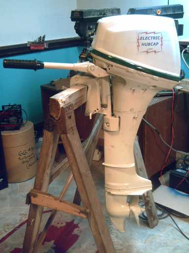 The painted Electric Hubcap outboard
After removing all the magnets from the rotor, I used a
liquid epoxy resin for glue and put the first six magnets on, and tried
it with just those at a wider .57" gap. The performance was amazing -
idle
current at 800 RPM dropped from 20 to 10 amps, a great improvement in
efficiency, and full speed RPM went up from 850 to 1460 (33 amps). And
that was still with just 24 volts instead of
36. After I put the rest of the magnets on, I gave them a thin, and
then a thicker, coat of epoxy, more or less encapsulating them in epoxy
plastic. This gives much more confidence they can't rip off than
simply gluing them on the bottom.
Thus, while other things
mostly related to motors and
controllers proceeded apace, October was largely consumed
by this one project. In it I learned things of great value about the
operating
parameters of the motors I created (especially the flux gap) and
better techniques for making them, and
will of course pass these on
in the motor building manual. I pressed hard daily to finish the
construction as I didn't want
one more project (supposed to be a couple of weeks) dragging itself out
into months.
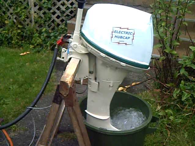 Finished at last! Churning up water on October 30th.
It works great, but owing to the geared-down propeller (almost 4:1
inside the leg),
the motor is "loafing along" at 1+ HP (34v, 29a) near its maximum RPM.
Options: increase the voltage (from 36v to 42v) to increase
the top RPM;
found a propeller with a steeper pitch, to push harder at a lower
RPM.
Sea trials will have to wait until November.
(If the winds of November come early, I'll test the wave power instead
- no need to emulate the Edmund Fitzgerald.) However, on the 31st I
removed the flat deck from the trailer and put on the boat guide rails.
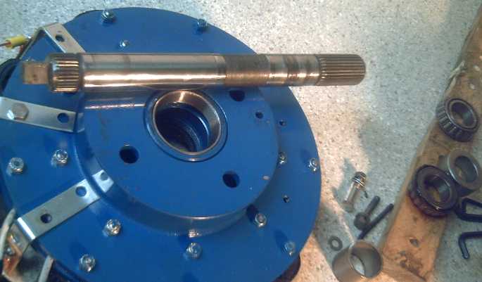
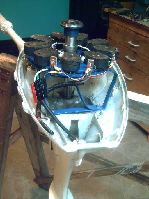 Under the hood: the 5 or so HP Electric Hubcap outboard (less magnet
rotor on top).
Under the hood: the 5 or so HP Electric Hubcap outboard (less magnet
rotor on top).
It just fits within the Honda 75 outboard hood.
By all accounts it should have way more push than when it was a 7.5 HP
gas outboard!
Small chassis motor controller *was* to fit in behind motor - na, too
much
extra work!
Concurrently, I made a new (and improved) motor
controller, also
completed and working on the 16th - it was with this that I ran the
outboard. I started it quite a few months ago when I got some polyimide
("Kapton") tape for heat sink insulation, but I didn't get around to
ordering more MOSFET transistors (had 8; needed 12) and finishing it
until this month.
This unit is for testing motors in the shop, but I'll also use it
onboard for the outboard.
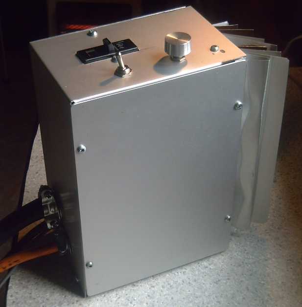 New motor controller for testing motors in the shop.
(...Now if only the chip wasn't being discontinued, forcing redesign of
the
logic board.)
I bought parts (except circuit boards so far) for the
three remaining MC33033 controller logic boards. After those, with the
MC33033 now said to be obsolete, the newer A3938 controllers will need
new circuit designs.
My first workshop
student has done several work sessions
making the parts for his Electric Hubcap motor. It's progressing well -
the bearing hubs and the stator coils are made, and the stator holes
are drilled. It is most helpful that
he's
very talented and has considerable fabrication experience. He had an
idea for tracing out the lengths on paper to break off each row of
nails for the
coil core, and this template seems to speed things up somewhat. Making
the cores is the most tedious part of making the motor.
 Motor under construction by workshop student:
Hubs turned, coils made (3 shown), stator holes drilled...
For my part, I've been
revising the EH motor making manual
(needs much more work) and trying to work out improved systems for
doing things. I calculated
the exact positions for drilling the holes in the stator and in the
rotor relative to the center so they could be drilled by CNC machine.
Then I made a solid mount (from a 12" diameter finned rotor - that's
just big enough to C-clamp onto the CNC's holding grid.) to hold the
stators rigid on the CNC
drill machine, and two plastic plugs to stick in the center hole to
center the
machine on the rotors - one for 'blank' disks and one for those with
with center hubs (smaller center holes).
I spent the day of the 29th with the owner of the CNC
drill/router machine getting the "G-Code" drilling sequence program
perfected and working through the various challenges that arose. But a
rotor was drilled and it's ready to duplicate them! It can be the first
custom part available for sale to help people who want to make the
motors.
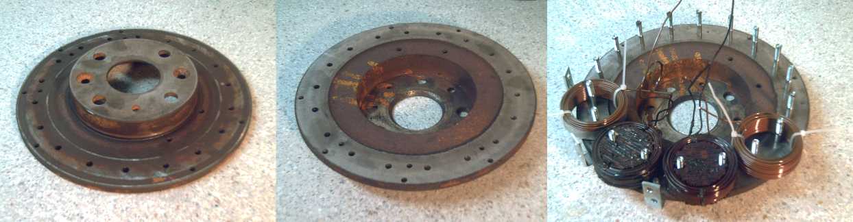 '6129' rotor: straight from a brake shop junk bin to first ever CNC
drilled Electric Hubcap motor stator!
'6129' rotor: straight from a brake shop junk bin to first ever CNC
drilled Electric Hubcap motor stator!
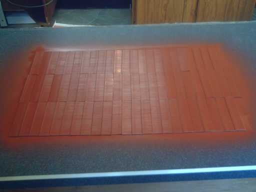 A small part of making an EH motor is painting the nail strips to
insulate between laminations.
A small part of making an EH motor is painting the nail strips to
insulate between laminations.
I did this job myself so the shop would be habitable during the
workshop
sessions.
I got the wave power unit "essentially ready" to test in
September, but calm weather in October up until the 23rd would have
precluded testing it even if I had
got a nice new planned load/test box completed, the trailer licensed,
and
the floats and gear loaded onto the trailer to be ready to take
advantage of good winds if they struck. By then the electric outboard
was about ready to go. I licensed the trailer and hoped for calm water
for boating.
I met a retired guy this month who said he used to work
for General Motors in the 1960's-70's. Among other interesting things,
he said the
engineers there
used to cry about all the patents, great ideas for better ways to do
things, that were acquired by upper management and tossed into drawers,
used only
to prevent anyone else from making the product or technology available
to the public. There's the scoop, straight from the 'front lines', from
an actual employee! This
is a symptom of why western civilization has become
static and unprogressive in key areas, and our biggest problems go
unsolved. Corrupt
vested special interests are permitted to man the decision switches on
the tracks to the future and send the trains around in circles,
when progressive solutions are in fact all around us. (...it also shows
how
stupid the
patent system is, that it can be and is routinely used to kill whole
new
technologies.)
I have written tirades about the gangsters running
the transportation industry and killing all but petroleum based
transport,
and also about the dysfunctionality of our
still primitive governing institutions that allow such cancers to
persist and dominate our society, and these are not without their
point. But there is a great principle that shouldn't be overlooked:
change begins with each individual. As we become spiritually liberated
through faith, as we consider the entire human race to be one family
under a
spirit father and take a
real interest in human and spiritual affairs, we gain broader and
more discerning viewpoints. We become world and universe citizens, and
we start to evolve a better
world that will marginalize the effects of the machinations of
these antisocial manipulative elements, by creating accountable social
institutions that fill the power vacuums that they now seize and
control. When
people are working in co-operation instead of against each other, our
planet's culture
will grow unimaginably.
The universes are evolving according to the all
encompassing, infinite and inclusive plans of the
infinite first source and center, the uncaused cause, often conceived
by relationship as being our heavenly father or spirit parent. His
mandate is that we evolve and become perfect - individuals, worlds, and
larger administrative units. In universe
terms, though they may work temporary harm and seem to prevail for
a brief cosmic time,
error and evil
are self-correcting and sin and iniquity are mentally destabilizing and
self-destructive.
Electric Hubcap System & Motor Building Workshops
First, I may perhaps point the reader to the Electric
Hubcap
Outboard Project write-up (below). In putting this unit together I
learned
some valuable things about characteristics of the motors themselves,
which are written up under that heading.
The most important one is that I found .57" to be a much
better flux gap than .35". The amps for a given RPM goes way down, and
the maximum RPM goes way up. This last would be because the (more
distant) supermagnets are generating less voltage back into the stator
coils at any given RPM.
I realize now I should have experimented with different
gaps more, earlier. I imagine if I now increase the gap in the current
car motor, efficiency and top RPM will also increase.
Another important lesson was learned: that the "Epoxy
Steel"
glue I've been using loses its grip after a year or two. Flying magnets
are dangerous. I've thought perhaps getting magnets that screw on as
well as glue on might be advisable. And yet most of the magnets are
epoxy
coated and that coating doesn't come off, and other motors have magnets
simply glued on. So I decided to try a liquid epoxy resin as glue on
the
outboard's motor. Once the magnets were on, I decided to paint another
coat over
the whole rotor around the magnets. This made them in fact
epoxy encapsulated, though only
thinly. Then I thought, why not make it a very thick coat? 'plasticize'
the whole rotor? It's hard to imagine the epoxy under the magnets, and
also going up the sides thickly, giving out in a couple of
years!
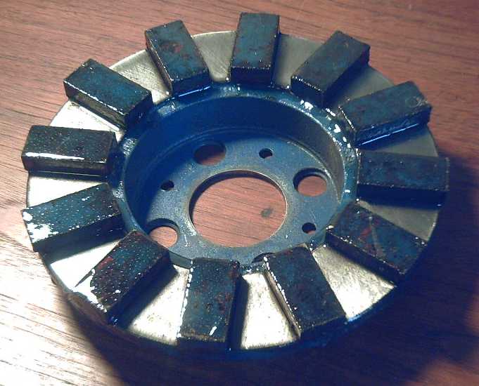 Epoxy "plasticized" magnet rotor: will prove durable I trust!
Last month I wrote that I welded the machined hubs onto
the rotors with difficulty. Both are cast steel parts. Then someone
chanced to say in some unrelated conversation something about "you
can't weld to cast
metal". This month I thought maybe some advice would be good and I took
the welded parts into a welding store.
It turns out that there's special welding rod for welding
cast steel parts. Two places didn't seem to have any. The second place
sold stainless steel welding rods by the pound, which I wanted a few of
for the pulsejet project. He asked me what kind of stainless - seems
there's enough difference between types of stainless steel to warrant
different types of stainless steel welding rod. I told him it was the
sort of tubing you'd find on sailboat railings. As I pulled some out of
a box
he held out to me, he said "Actually, these would be good rods for cast
metal too, oddly enough." Alright, problem solved!-- the same stainless
rod for
everything! They
only had it in 3/32" diameter size, and I'd never had much luck trying
to weld
with
anything bigger than 5/64" rods before, but these worked great, and on
the cast metal. These
rods were titled on the receipt: AVE-E316L1725 Electrode, Stainless
Steel, Avesta, E316L AC/DC. 2.5mm (3/32") x 3.63KG (8LB), AWS E316L-17,
AVE-60610125. (Remember that when you're looking for them.)
Stainless seems preferable for an outboard, and I was told
the rods for cast metals were best run with a DC welder (mine's AC),
whereas the
stainless ones (per receipt) were AC/DC - good to know. There were many
interesting hues in the finished welds - yellow, red, purple. Makes me
nervous about the fumes during welding: yellow - cadmium?; red -
copper?; purple - manganese?
Later I was trying to pound a bearing race in and the
welds broke. More precisely, the cast steel of the rotor broke where
the welds were. There's no question that welding to cast metal isn't as
strong as to rolled or extruded metal. For the repair I did what my
neighbor suggested in the first place and welded it all the way around
(well, more or less),
not just some spots.
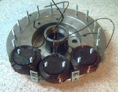
Another improvement was a better defined system for
mounting the three magnet position sensors. It uses three angle
brackets bolted between three pairs of coils on the backside
of the rotor, but with the vertical angles sticking up just outside the
stator's edge to near the magnet rotor. (See picture of open EH
outboard.)
By bolting them on from the backside, they can be removed for servicing
without disassembling the motor. Some sort of circuit board or
PWB is bolted to a couple of #6 or #8 threaded holes drilled in that
vertical leg, with the actual Hall effect sensor soldered to it and
sticking though the
top original hole in the bracket. Two of the motor mounting holes are
shared by the brackets. Timing can be adjusted by bending the bracket
left or right a bit (crescent wrench) until the sensor is dead
center
between two coils.
And I did a technique for placement of the holes in the
stator:
a cardboard photocopy of the drawing is used as a template, with the
center hub
cut out of it with scissors. This is placed over the center hub of the
actual rotor and taped in position so it can't rotate. Then a center
punch is used to
position the drill holes.
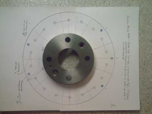 Rotor with hole center-punch template - a photocopy of the drawing
Workshop student's motor stator, holes per template
(Showing how coils & magnet sensor brackets fit,
with bracket & motor mounting bolts in the small 'corner' gaps
between coils)
Next, though, is CNC hole
drilling to automate the process. I worked out the stator hole
positions in 1/1000ths of an
inch from the center. I couldn't
find a drawing program that would rotate things around a center and
give me the numbers, so it was oodles of sines, cosines and multiplies
with a calculator. I used a 12" finned rotor as a hefty holder to hold
the rotors completely rigid while they're being
drilled, and made a centering ring that fit over the center hole. I
worked with the
guy with the CNC
drill/router (homemade!) to tweak my "G-code" program, and to get the
somewhat neglected machine working smoothly again. We drilled one
stator, and more can now be done repeatedly, automatically. And then I
expect we can
expand it to the rest of the
motor and motor controller pieces.
Marketing "ready to use" parts could
perhaps bring some income while making the job easier for those wishing
to
make their own motors - and without the potential liabilities of
selling
complete motors having a novel new - and therefore "untried" in the
commercial sense - construction.
I think that if four specific custom
parts can be made available, building a motor will be reduced to "bolt
it together" and "wire it up". Those parts are:
* Pre-turned bearing hubs
* Ready-made coils
* The three magnet sensors, mounted on angle brackets and wired - ready
to install
* The pre-drilled & tapped stator (29 holes)
Of these it could be said that the ready-drilled stator is
the least
valuable, because drilling the stator is the easiest of the above. One
can always print out the drawing and tape it to
the rotor for use as a template to center punch for the holes, then
drill them manually accurately enough. Nevertheless
the ready part represents a labour saving that isn't trivial.
I put together a Turquoise Motor Controller for testing
motors in the shop, completed on the 15th. I especially needed it
to test the EH Electric Outboard Motor I was making - and maybe to run
it on boats. Initially it
didn't work. I finally found not one but three
main problems:
* One of the 12 MOSFETs was shorted to the heat sink through the
"Kapton"
polyimide insulating tape. It's tough, but it's very thin. (I *think* I
sanded the aluminum bars quite smooth when I made them...) I suspect
there may have been some little grain of metal present that punctured
it when
the transistor was bolted down. I simply added another layer of tape,
since better solutions involved a lot more work. That seemed to fix it.
* I had put the two header sockets on the PCB board the wrong way
around, so that when I plugged in the plugs, they were backwards. (That
kind of negates the value of using polarized connectors!)
* A resistor was missing for the overcurrent protection, and it thought
the current was always way too high. (Well, it was way over on an
obscure corner of the circuit board, see...)
These glitches solved, both the car motor and the
outboard, newly ready,
were run
on the evening of the 16th, using two batteries for 24 volts.
Then, since it was for shop use, I mounted an OFF-FWD-REV
switch (FWD-REV direction arbitrary) and a volume control (to make the
motors
louder or quieter) on the top of the controller box itself, near the
breaker switch.
There's an improvement or two in this unit. Especially,
the terminal blocks for the heavy 3-phase wires have been moved from
the wiring box back cover onto the motor controller side, much reducing
the chances of the vulnerable mosfet leeds getting yanked off during
servicing. In
company with this, their mounting block now has an angled base in order
that screwdrivers are inserted at an angle -- thus the handles don't
have to magically occupy the same space as the far wall of the
controller. This will avoid much aggravation.
Mechanical Torque Converter (MTC) Project
On one test the escapements were just light aluminum, and
the torque was poor. When mass was added to the escapements, the torque
increased surprisingly, verging on enough to move the car. But the
light torque converter output drum was vibrating back and forth against
the pins to the wheel. Last test, I tried adding a steel plate to the
drum, but the results were inconclusive.
There is however one more place where mass might count,
and that's
in the motor rotor, the input to the torque converter. It's already a
beefy car disk brake rotor, but adding some weights might be a good
experiment. If it's being slowed too much as the escapements hit the
output drum, that could reduce the torque.
In addition of course I must finish the experiments I
had already planned: having six escapements instead of three (bound to
be even noisier?), 27 teeth on the drum instead of 25 so that the three
escapements all hit at once with a force that's balanced around the
rim, the single 'full circle' escapement (maybe), and a larger diameter
for more torque leverage with the heavy cast 15" wok.
Wave Power Project
Wave power tests had to await strong winds from the
southeast or southwest to bring waves to area boat launches. These were
not forthcoming until late in the month, plus I was busy with the
electric hubcap outboard and didn't get everything ready to go for when
wind finally did strike.
Solar Powered Electricity Plant with flat mirror collection
(What does this have to do with wave power? Well, not much!)
I have been advocating wave power on the west coast in
lieu of the Peace River Site C dam, but there are other neglected clean
alternatives too besides wind. A great example is power directly from
the sun. Sunlight has about 100 watts per square foot or 1000
W/sq.meter, so over a few square meters, there's quite a lot of power.
A large
power site, such as one recently installed in Arizona or California
(I'm going from memory here), consists of many acres of large ordinary
mirrors mounted on swivel bases, all reflecting the sun onto a
collection tower to heat water, to
power a typical steam turbine system.
A computer system
aims all the
mirrors, and a cleaning machine automatically goes up and down the rows
spraying dust off the mirrors.
The radiant power from the sun on the Earth's surface with
no clouds is about 100 watts per square foot. Thus an area about 100 by
100 feet, directly facing the sun on a sunny day - a couple of city
house lots - gets about a megawatt. Okay, we won't do that well in
Canada in the winter. And the site will have to at least survive snow
if not continue operating in it, perhaps feathering mirrors to vertical
- not a concern in warmer climes. Say we get 23% on flat land in an
area that gets lots of sunshine per year (probably not the west
coast). Let's say we'll need an area about 208 by 208 feet (one acre)
per megawatt. A 900 acre site, 1.4 square miles, or, more practically,
the same overall area made up from a number of smaller facilities,
would be
required
to obtain the same 900 MW power capacity as the proposed Site C river
hydro.
That's far, far less land than is to be flooded for the dam. And taking
advantage of south facing slopes could increase winter effectiveness
and reduce land use requirements.
I can't undertake to estimate what the capital cost would
be. But like wave power and unlike the giant river dam, it could be
built in stages, each of which would start contributing power as soon
as it was built. From the first installations (as well as taking
advantage of suppliers, services and lessons available from existing
installations elsewhere) would come the practical experience and
infrastructure to create cheaper, better additional sites adapted to
our conditions.
Large capacity
sites are considerable projects that will be difficult of realization
unless the government is on side (although perhaps not as impossible as
with wave or river power. Hah! - Try and imagine Site C dam going ahead
via
BC's
"private power producer" program with a few million dollars from the
ICE fund and no other government support or "okays"!)
Backyard Solar Electricity?
At a glance small sites might not seem very practical -
you
won't find steam
turbines or computer controlled 5' x 7' mirror swivel mount systems at
Home Depot. But talented hackers
could create - or perhaps even produce for sale - smaller sites using
Stirling engines instead of steam turbines to drive a generator, if a
system can be worked
out for tracking the sun with a parabolic dish or relatively smaller
flat mirrors. A system of "n" individual mirrors in any flat field,
throwing 10 x 10 meters of sunlight at a Stirling engine on
a stand, might produce 30 or 40 kilowatts (peak) - a sizable 'reverse
metering' installation for selling power to the grid from home and
repaying (at only 5 cents/KWH) over $360 per month in a sunny area.
This is at least double the power of solar photovoltaic collectors and
the
components could be cheap in principle.
Such a project would ideally include at least a mechanical
designer to do the Stirling engine and an electronics designer to do
the mirror tracking system with (as I see it) microcontrollers on each
mirror, a central override to aim the mirrors away (for servicing) and
stepper motors. Individual equatorial-mount mirror stands might point
due south and also have an arm pointed at the stirling engine to
indicate to the microcontroller where to aim the sunlight, making setup
adjustments trivial. Seasonal 'tilt' adjustments could possibly be
manual. The rest is 'regular engineering'. There is information
on Stirling engines in
Wikipedia, various plans for making them on the web, and an aluminum
wok lid
solar powered Stirling engine video - among others - is on YouTube.
[http://www.youtube.com/watch?v=7Q4UENGN_Yk]
But I gather that, theory aside, making a larger, efficient
Stirling engine is a considerable project. It could be argued that
photovoltaic
panels might be more practical. In particular, lower cost DSSC
solar panels that might be almost
20% efficient could be made with
my nanocrystalline ceramic rear reflectors, which would be heading
towards what might realistically be achieved by small Stirling engines,
and without the moving parts. Depending how much sunlight the panels
could actually absorb without overheating, they could have angled
mirrors at top, bottom and sides to reflect more light onto them, and
if
desired they could follow the sun on equatorial stands in place of the
mirrors, to collect full sunlight over much of the day. And since each
one would face the same way, a single sun tacking system mechanically
linked to many panels would be practical.
If they can
withstand a whole pile of light, they could be at the focus of the
mirrors in an arrangement similar to the steam turbine or Stirling
engine, further reducing the number of collectors needed.
(This makes me want to get back to the DSSC solar cells
project, and make actual working cells rather than just the
nanocrystalline rear reflectors for them. Mass-produced, they may have
much more real energy potential than I thought!)
Pulsejet Steel Plate Cutter Project
I got some pieces of stainless steel tube from from the
stainless steel fanatic next door. I got three virtually telescoping
sizes, and a piece of a .303 rifle barrel. It seemed to me to be a good
size for the output jet. (I could also have had a piece of .22 rifle
barrel - perhaps that would take less "kerf" from the steel?) I also
got stainless steel welding rod and some steel balls - ball bearings.
I thought it should work better with one moving part: an
air intake one-way valve to keep it from firing flame out the air
intake port when the fuel burned. I'd rather have the entire jet
concentrated against the steel plate that's being cut. The V1
'doodlebugs' had some sort of flaps, but the hobby pulsejets don't. I
was told people had tried making flaps, but the reliability was poor.
(It may have been poor in the doodlebugs, too, but they each flew only
one flight!)
My idea is, instead of a flap, to use a ball bearing ball
that free-floats in a small chamber. It gets shoved against the air
intake pipe by the expanding air when the jet fires, closing the pipe
off. The 45º slope of the seat is such that it would be hard for
the ball to jam. At the other, inner, end of the chamber are air slots
so that when the ball is pushed to that end it can't impede the
incoming air. I drilled out this cavity from the rifle barrel piece and
threaded the inner end on the last day of October. The inner piece with
the slots, outside threaded, will be next. That will be welded to (or
threaded into) the body of the pulsejet torch. (intake pipe: ~4/16"
I.D.; ball: 5/16"; chamber: 6/16" I.D.; threads: 7/16" NC.)
Materials acquisition, the concept for the one-way ball
and an overall shape, and the making of one side of the ball chamber
were the only progress on the project during October.
The jet wave pulses travel at the speed of sound, and
ideally, I think the entire chamber would be a tuned, inverse conical
bore like a recorder (the musical flute), perhaps about
flautino/sopranino size. This idea was supported by a
set of pulsejet plans e-mailed to me in which the main part of the
combustion
chamber had that inverse cone shape.
The "Supercorder" alto recorders I developed a few years
ago sound fabulous, but I'm not about to make a "flute bore reamer"
capable of milling stainless steel. So I decided to just use the two
telescoping tube sizes, and then
"telescoping" drill bits
of progressively smaller size, deeper and deeper into the rifle barrel.
This may require finding a couple of long, thin drill bits.
Electric Outboard Motor Project
Making an Electric Hubcap outboard quickly became
October's main
preoccupation. The project's main goals are:
1. To compare the
performance of an Electric Hubcap axial flux permanent magnet motor to
a typical radial flux induction motor (an existing electric outboard
motor)
consuming identical watts of electricity. Even once the motors are
running cars, it will
be difficult to make such a direct demonstration, since it would be
impractical
to make an induction motor version of the car drive.
I'm expecting a good increase in thrust. In fact, I suspect that
virtually no other motor will match the EH's performance except maybe
some other axial flux supermagnet motor. This project is the best way
to demonstrate that.
However, since the induction motor outboard is 24 volts, 2
HP, the EH outboard will be run with the same limiting parameters,
whereas it should be capable of about 5 HP at 36 volts.
2. To demonstrate a practical use of the EH motor other than as a car
drive.
3. I also hope to find that the thrust from the 5 HP Electric Hubcap
outboard is noticeably greater than that of the 7.5 HP gasoline engine
that previously powered this same outboard. That engine could just get
my 14 foot aluminum boat up on a soft plane with one person on board.
If the electric hubcap motor can do the same thing with one person and
140 or more pounds of lead batteries on board instead of a 20 pound gas
tank, it's better. From what's been said in marine circles about 1 HP
electric being equivalent to 2.5 HP gas and the Electric Hubcap being
in the most efficient (axial flux) branch of the most efficient family
of electric motor, I'm optimistic it will
do even better than that and
provide "speedboat" performance, equivalent to around 15 HP gas.
I spent some fruitless hours searching for a scrap
outboard to use for this project. One recycler said fall was the wrong
time of year - outboards get tossed out in the spring. An outboard
shop said the ones they'd been seeing were from the 1960's and 1970's,
looked awful, and were going straight into the scrap bin -- and that
that had been emptied just two days ago. Another outboard dealer had a
whole storage room full of dead outboards for parts, but wanted
$200-$250 for any of them. I passed.
So finally I decided to dismount the gas engine from the
top of my 1976 Honda 7.5 HP, trusting that it could be put back on
later. It
seemed about the right size. I hadn't run it in about 15 years anyway!
It
turned out to be much more complex than I'd envisioned, the engine
extending into the outboard leg in a mechanical nightmare arrangement
instead of simply being mounted on top like on a gas lawnmower, and
soon I
realized I'd disassembled so many things that I'd probably never want
to try to
put it all back together again. Scratch one perfectly good gas outboard!
Then several bolts broke off instead of unscrewing,
including some critical ones for the water pump. And the drive shaft
was pried out of the gear case through the water pump to get the leg
apart, instead of separating at either of two points where it should
have slipped apart. These seized "slip-on" joints had to be heated red
hot
and pounded loose later. The drive shaft got much bent up in the
process, so it had to be carefully pounded more or less straight again.
Overall, it took most of a week to disassemble and clean
up the diabolical and corroded unit - my vision of the total time it
might take to
have it initially running - without even starting on the electric motor
part! On
the bright side, it's a great fit, in an outboard leg of about the
right
size and power capacity.
Most smaller outboard hoods would have been too narrow for the EH motor.
The electric part went easier. I mounted the motor stator
in a day, making an "origami" single piece main mounting bracket from
strap
steel, that used existing bolt holes on both the outboard and the
stator. And I turned a hub from my supply of "hub blanks" -- 1-1/2"
cast threaded pipe couplings -- and welded it to the (cast) stator disk
with stainless steel welding rod, a recommended type for welding cast
parts. I didn't worry about how I might seal the bearings -- none of
the trailer type bearing seals were going to fit. This motor won't be
collecting any road dust, but salt water may be another matter.
The next day I picked a scrap (car part) 1"D x 9"L splined
shaft for the axle, the requirements being a little different
than for the car drive. It proved to be just long enough. The bottom
end I carefully ground down to a square to fit into the splined socket
(alas, a smaller spline than the axle's) on the outboard's drive shaft.
Square fit in, driving four of the sixteen splines. I also found an
"SD" type compression coupling for 1" shaft to attach the magnet rotor
to the axle, which I had no idea how I was going to do until I saw one
on a shelf... AHA! (BTW This magnet rotor was the extra-scary one with
18
magnets on it. I thought it would be asking for trouble to try to get
them off and redo it with just twelve.)
 The (car transmission) axle, with the end ground down to a square
that
fits
The (car transmission) axle, with the end ground down to a square
that
fits
in the outboard's splined drive shaft socket, here sitting on the
stator.
The 3 hall effect sensor brackets on the stator are seen at far left.
On the 14th I installed
three angle brackets to mount the
magnet (hall effect) sensors on, put on the magnet rotor, and then
started on the motor controller. I finished soldering that together and
also installed a circuit breaker and did some of the chassis wiring.
Later I put the top cover on the outboard. There was lots
of room from the magnet rotor to the top of the cover. I reached
in through the starter rope hole and turned the motor by hand. One
magnet stuck out about 1/8" farther than the rest. It, and it alone,
rubbed on both sides and the front of the cover as it turned!
I tried to cut off the protruding end with a zip disk on
the angle grinder, but suddenly the whole magnet broke loose. So I
removed it. Then I was worried about balance, so I tried to pry off the
antipodal one. It too came loose, without trouble. Great! But I started
worrying about magnets breaking loose, and I became more convinced than
ever
that they should be screwed on as well as glued. But maybe I should try
some other type of epoxy before giving up - they just glue lawnmower
motor magnets on, and those... except for on my lawnmower...
it
seems rarely
fail.
It's lucky my original (well, first *successful*)
prototype motor had a slightly smaller diameter than the later ones and
that that was the motor I used for the outbaord project. (And I almost
remounted the coils on a larger rotor - nah, too much work.)
On the 15th I finished putting together a second Turquoise
Motor
Controller to have one in the shop - it was needed generally and I
wasn't about to drag the outboard out to the car to plug it into the
one there. It didn't seem to work (with the car's EH motor either). On
the
16th I mounted the hall sensors on the outboard, and got the controller
working (Details on that under "EH Motor Making"). I didn't
yet have the proper power cable plug for the outboard's motor, so some
brand new skinny little alligator clip leads (#24 wire) were given a
real workout. Though quite hot, somehow they survived some short bursts
of several tens of
amps.
I had bought an AC/DC amp probe that hooks up to a volt
meter, so at last I'm able to measure the total DC current coming from
the
batteries, which I did with the speed control turned right up. Some of
the figures
(steady state, no load, 24 volts) were interesting:
CAR MOTOR: 10 amps at 800 RPM. (240 watts) The three motor phases
didn't seem very balanced, reading 7.2 A, 5.5 A and 7.5 A.
OUTBOARD: 22 amps at 850 RPM. (550 watts). I didn't measure the AC
phases.
For a brief time I was thinking that seemed like a lot of
power - over twice as much - to keep the slightly smaller motor on the
outboard turning not much faster than the large one. The differences in
the coils didn't seem like enough to explain it. Then I realized the
main difference was that the car motor had no load, while the
outboard's motor, though it had no "real" load, was turning the drive
shaft with its 90º gears and the propeller. The gears are in an
oil bath. The gearing seemed to be about 11:3, so the propeller would
have been turning about 230 RPM.
This seems like a good illustration of the power consumed
by a gear transmission drive system. It definitely takes more force to
turn the outboard's motor by hand than the free one.
But later I discovered that a wider magnet flux gap (.57")
reduces current and increases maximum RPM by surprising amounts, and
the car motor's gaps, while under 1/2", were wider than the outboard's,
doubtless accounting for part of the difference.
Next question was whether to make a motor controller
especially
for the outboard, in a compact box that fits under the hood, or just to
use the external shop one. It would be cool to have everything enclosed
inside the outboard, with the controls where the starter pull was and
just the two battery cables coming out. That would be the obvious
choice if it was to be used more than rarely. I finally decided on the
external unit, since another controller was another small project in
itself, and doing a mini-box controller might well have unforeseen
headaches, too. The outboard motor "side project" was already
stretching into some
weeks.
But the outboard wasn't through tossing in nasty
surprises. The steering wouldn't move, and I had assumed there was some
sort of silly little interlock tied in with the tilt system that was
misbehaving. Wrong! Inspection disclosed that there was no such
interlock, and that in fact the stainless steel pivoting tube was
somehow totally seized in
place by the plastic sleeves. Even after I got it to move, only
powerful brute force could swivel it left or right, and a week of
moving
it back and forth and pouring in WD-40, oil, solvent, toluene,
methylene
chloride and methyl-ethyl keytone wouldn't loosen it up.
After hours of brutal manipulation in two
fruitless sessions with two people, in which the stainless tube was
worked out just an
inch and actually got bent, and I hurt a rib and my back, I
finally got the idea to blast a
propane torch flame right through the tube, which was open at both
ends, to
soften or melt the surrounding plastic. The plastic caught fire a few
times, but
after 3 or 4 torchings, the tube finally came out. Once it was
*finally*
apart, the top and bottom plastic sleeves virtually fell out, leaving
the long middle one in place, and it
was easy to
ream and file out the three sleeves until they fit easily over the
tube. On pounding the tube straight again and slipping it back in, the
steering was free and easy. The plastic presumably must have gradually
swelled or
something to put such friction on the tube. It seems strange that
either stainless steel or "inert" plastic should have swelled or
somehow changed over the years to produce this problem. By some small
miracle, none of the vital cast 'pot metal' body parts got broken in
all this. (Earlier I had broken a piece off the anti-cavitation plate
when trying to get the leg apart - not good, but not vital.)
I had started by thinking the 26cm axle shaft was too
long and might have to be cut shorter with the angle grinder,
but once everything was in place, the rotor holder was clamped to less
than an
inch of the axle at the top, and the rotor wasn't sitting quite
straight. While I had the
motor apart again for the steering, I decided to lower it 1/2" - all
the clearance available - to get a bit more shaft at the top to clamp
the rotor to. That meant re-bending the metal mounting bracket and
getting everything lined up nicely all over again.
In this, I tried to pound a bearing race in farther than
it wanted to go, and the hub welds broke. One of the four welds had
spray paint in it, which meant it wasn't welded to the rotor in the
first place, only to the hub. Next time, I'll put down even more weld,
and more carefully melt it to the rotor before getting it to the hub,
but on this particular motor, with the axle held centered at the bottom
by the drive shaft, it appeared (for the moment) that fortunately the
hub welding wasn't
really necessary anyway, and that adjustments were easier without it.
By the 23rd the adjustments, painting et al were ready. I
bought narrow headed bolts for the shaft collars, cut a keyway into the
axle to match the one on the shaft collar, and put the magnet rotor on.
Still not very straight - oh well! That 1/2 inch gap between rotor
magnets and stator coils has its advantages! I ran the motor again,
with about the same results electrically and similar amounts of
vibration.
Then I decided not
to make a special motor controller in a miniature chassis to fit under
the hood since it would be another small project in itself. Instead,
I would just use the new shop controller in the back of the boat. But
I'd made the motor cables too short for that. With the weekend on and
ECS Cable closed, I painted the
rubber hood base dark green for effect (I'd sprayed it white with the
hood), then found some transparent adhesive
labels [Staples Office Supply] and made
up a logo saying "ELECTRIC HUBCAP .com" with a frame of lightning
bolts. With nice fresh paint and fancy labels it inspired confidence
that it just had to work great, too - how fickle we humans are!
I got a rubber "cab tire" cable for the #8, 3
wire, motor power on Monday the 25th and did the rewiring.
The painted electric outboard
Presumably the motor
was at
last finished, but in the next
test (with the cover off) one of the supermagnets flew off like a
bullet. It scored a
bullseye on some empty plastic sodium sulfate jars on a shelf, sending
some flying. The one it hit had some deep scratches and was coloured
with
a rectangle of the magnet's paint. I decided that the "epoxy steel"
glue I've been using must not really be very good - it seems to loose
its grip
over a year or two - and I decided to try
taking more magnets off - hopefully all of them at that point - and
re-gluing with a different kind of epoxy. Sure enough, they all came
loose with a sharp tap of the hammer -- with much of the striking force
provided by the magnet itself attracting the hammer. One seemed better
stuck than the rest and I chipped it (small chip), but finally it too
came loose. As a silver lining
(besides having not been hit by the flying magnet), I could
reduce the
"overdone" 18 magnet rotor to the "optimum" 12 magnets and have 6 left
over for another rotor.
On the 26th I put six
magnets on the rotor with a liquid epoxy resin,
and on the 27th decided to try it with just those before adding the
rest. I also increased the flux gap from
1/3" to .57", which gap (.55") I'd seen mentioned for another axial
flux motor
of similar power. The motor had less torque - fewer magnets at a
greater distance. In fact I could hold it
stopped with my hand even at full power. (...drawing 40 amps - gosh,
I'm really glad I finally got a DC clamp-on ampmeter, even if it was
$90.) But once it was
moving, it was smoother, and it was unstoppable! At only part power it
was doing 800 RPM and drawing only 10 amps, a great improvement in
efficiency. At full power it was at 1460 RPM and drawing 33 amps. The
unwelded hub was rattling fiercely. Even with the hood on the motor,
this was scary! (Obviously the unwelded hub wouldn't do, and I
re-welded it a few days later.) And all this was still with just 24
volts battery
supply instead of
36. I was almost scared to try it at 36 volts -- in air it might
over-rev!
This experiment led to a couple of valuable conclusions
about the Electric Hubcap motors that I hadn't caught before:
1) The motor works much better and much more efficiently with a flux
gap of at least 1/2" than with the smaller gaps I've been using like
1/3", and still better than with even smaller gaps like 1/4" or less.
However, even with supermagnet magnetic fields the flux drops off
rapidly with
distance, and I can't see going much wider. (Of course, I couldn't see
going to 1/2" before, either!)
2) Smoothest operation appears to be with single magnets in
each pole
position - double magnets introduce more vibration and probably torque
ripple. The motor made strong vibrations with some of the magnets
missing as I was taking them off. (Yes, I tried running it with various
opposite-side pairs of magnets missing as I took them off, to see how
it might work. Towards the end, sometimes it had to be started by hand,
when magnets were too far away or too unevenly spaced from the Hall
effect sensors to get them to work properly.) However, with the wider
gap, evenly spaced double magnets seem to
introduce trivial vibration.
3) 12 magnets are still required for good torque and maximum power -
especially with wider gaps. But it may be that some uneven spacing of
magnets, eg with pairs having like poles closer together, will give
smoother operation or better torque. This could still use some
experimentation, but I'm happy enough with even spacings.
On the 28th I put the other 6 magnets on the rotor, and on
the 29th I put a thin coat of epoxy over the whole of the
magnets and their area of the rotor, virtually encapsulating it (if not
very thickly) in epoxy plastic. On the 30th, I decided that seemed like
a great idea and put on a second, thicker, coat. I have much more
confidence that the magnets should never come loose.
Water Pail Test
Then when that had set, I put the rotor on and tried out
the motor. It seemed to run fine. With my workshop student's assistance
we dragged the finished
outboard and three batteries outdoors and ran it in a garbage pail of
water. It ran great, the meters showing 34 volts, 29 amps,
and about 1740 RPM. Lots of water was being churned up strongly, but I
was
disappointed that it wasn't spewing out of the bucket. (Would make
better video!) The indicated
power, 1 KW, was only 1-1/4 HP, the low current indicating that the
motor wasn't
doing a lot more work than just loafing: the load was unexpectedly
light. The motor
controller heat sink remained cold, and the motor coils were still
almost cold after a few minutes of running.
Electric Hubcap Outboard: first in-water test
Movie Here
The problem is of course
the 11:3 gear reduction from the
motor to the propeller. At full RPM, the
motor isn't turning the propeller as fast as it ought to be going. One
to one or even two to one gear ratio would load the motor down much
better and move a lot more water, but the ratio is
built into the outboard leg. Two things that can be tried are (a) to up
the
battery voltage, say to 42 volts with an 'extra' 6 V battery, which
will up the motor's maximum RPM some more, and (b) to try and find a
steeper pitch propeller, which will push more water at a lower RPM.
Above 42 volts is endangering the 60 volt rated mosfets in
the
motor controller (considering voltage spikes from the coils), as well
as starting to get dicey for humans, especially in a wet boat, and
heading towards speeds well over my recommended 2000 RPM upper limit,
that might be hazardous with the
fat EH motor - epoxy encapsulated magnets and all. (The centrifugal
force is proportional to the square of the speed. If one is ever
running over about 3000 RPM, I don't want to be in the same room with
it!)
Still, even at 36 volts, in a boat and turning still water
instead of water that's already circulating in a pail might make for a
notably greater load, and the boat's performance might be fairly
impressive. And if not, the silver lining: the batteries should last
around two hours at that low current draw.
On November first I found a steeper pitch propeller. It's
not the right one or an exact fit, but the diameter is right and the
shaft size is close - I'll get it to fit with a few custom measures.
Plug-in Hybrid Boat
Someone suggested that the electric outboard could be
run from a generator. A portable generator on board makes a great
"plug-in hybrid boat" idea,
especially for longer trips: it
would eliminate the danger of being stranded on the water if the
batteries got low.
Sacrifice... or Upgrade?
Though I initially
regretted sacrificing my Honda outboard
for the project, the EH outboard should outperform it and run more
quietly
too, so assuming the battery
project gets
successfully completed, I'll probably never want a gasoline outboard
again. (...or any decent battery project... where are those cheap 70-80
WH/Kg
nickel-iron dry cells from Bangalore, India? Perhaps Tata Motors in
India will have
them produced to use in their $1,999 electric cars [importing these is
banned in USA - unfair competition for all those American electric cars
you see advertised on TV]
and for the electrical
items in their new 300 Km range, fast refill or home refill, petroleum
free compressed
air engine vans!)
Turquoise Battery Project
Carbon Experiments
I've been trying to learn how to make highly
conductive carbon sheets for the positive electrodes, but instructional
information is vague and
even the few
tidbits of information about the raw materials are confusing and
sometimes in conflict with each other.
In the search for
carbonaceous materials, I found that
"pitch", "road tar" and old "creosote" from a wharf seem to be pretty
much the same thing.
Then, "lamp black" and "carbon black" are evidently the
same thing (but not
to be confused with "black carbon"), and may perhaps be describable as
"surface
oxidized graphite". carbon-black.org says: "Carbon black is
chemically and
physically
distinct from soot and black carbon, with most types containing greater
than 97% elemental carbon arranged as aciniform (grape-like cluster)
particulate." It also says that it's used to make non-conducting
products conductive, whereas the Wikipedia article says it's a
non-conductor owing to chemisorbed oxygen complexes on the surface.
What was that compared to
the stuff that I'd
cleaned out of the chimney? Though usually called "creosote" or "soot",
It seems
more like light, airy charcoal to me, and I thought the Wikipedia
article on "charcoal" seemed to hint it probably had that sort of
composition.
"Charcoal" it seems is 50-90% carbon. But the article was
unenlightening on the non-carbon composition, electrical or crystalline
properties, etc.
It ground into a coarse powder with mortar and pestle. It
was hard to get a resistance reading, though if the probes were
virtually touching, a low to medium reading might be had across,
perhaps, single grains. This is quite different from graphite powder
where
simply dipping the probes into a jar of loose, uncompressed powder
gives a
reading of only hundreds of ohms. I guess it's not good stuff to use.
Then again, what about that compressed, graphite
impregnated plastic? GraphiteStore.com had some intended for fuel cells
- doubtless closely related - in fact, probably intended for the very
same purpose. Hmm, a compressed composite... And the dry cell
electrode rods were a dense carbon substance.
So a good experiment, since the more conductive carbon
things all seem to be higher density, might be to try to compress one
of those light sheets of graphite to see if it could indeed be
compressed in the electrode compactor, and if so, if the resistance
dropped by much. That would be easily tried!
The initial thickness was 1.6mm, and the resistance
readings were typically about an ohm anywhere across the thickness and
1/2 an ohm if both leeds were on the same side of the sheet. (This is
considerably more conductive than I thought, which is probably related
to having just replaced one of my multimeter leeds, which had been
going bad over the last few months.)
After compaction, the thickness was uneven, 1.0 to 1.5mm,
with one corner seemingly little compacted. Had the compactor "bottomed
out", since I hadn't planned on compacting that thin? The resistances
on one face were about the same, but the resistances between faces were
now also down to about 1/2 an ohm.
I decided to try again, with a plastic insert to push the
die down farther. Sure enough, it compacted down everywhere to between
about .8 and 1.0mm. Resistance readings between any two points were
about 1/2 an ohm. Well, interesting and informative. Compacting is part
of the answer, but simple graphite sheets will doubtless still degrade
and swell in the battery.
If pitch mixed with powdered graphite can be made with
similar
low resistances, perhaps the pitch would prevent the graphite from
swelling. If only it wasn't so sticky, and didn't have to be so hot
when working with it, it might be great stuff! As it was, I stared at
the tarry cookie sheet for a good portion of the month before I went at
it with paint thinner to clean it so it could be used again for the
next
experiment. More rewarding to work on the electric outboard! Of course,
once that's working, all the more will I want superb batteries!
http://www.TurquoiseEnergy.com
Victoria BC