Turquoise
Energy Ltd. News #34
Victoria BC
Copyright 2010 Craig Carmichael - December 1st 2010
http://www.TurquoiseEnergy.com
= http://www.ElectricHubcap.com
Contents/Highlights:
November in
Brief
(summary)
* A month of further development and refinement of the EH motor
Electric Hubcap System & Motor Building
Workshops
* Electric Hubcap Motors get Better and Better!
* EH Motor Testing: proving the efficiency and power; the motor
with adjustable performance specs!
* Magnet Rotors: Epoxy-polypropylene composite skin strengthens
magnet bond to rotor
* Welding bearing race hubs: preheating parts with torch
improves
hub-to-rotor welds
* Jigs, CNC drilling improve motors & speed making them
* Motor controller: Designing for serviceability is paying off!
* New Motor Controller printed circuit board designed - smaller
PCB uses improved A3938 chip.
* First motor workshop student completes his motor!
* Small business opportunity? for Victoria BC residents:
make
& sell Electric Hubcap motor coils, magnet rotors (sales
opportunities
per market demands).
* Making & marketing motor
components online to simplify making more marvelous motors
* Lower price
parts sources found: estimated parts cost to make an EH motor down
from almost $400
to under $300. (That's still buying parts at retail prices.)
* Lower cost for
workshops: $700 or less.
Better Blades for Windplants (just
some cool ideas... not a project)
* Residents object to nearby windplant noise.
* Here are ideas for quieter, also durable and
reproducible, windplant blades.
Torque Converter
Project
* Plan for modifying existing escapement converter -- 5-at-once
torque hits instead of one at a time should substantially boost
performance.
Pulsejet Steel Plate Cutter Project
* One-way air intake made, main parts cut out, welded... a
couple of parts left to make.
Electric Outboard Motor Project
* Steeper Pitch Propeller installed.
* On the water: Runs great, quiet!
* Movie Clips are on YouTube
(Search there for "Electric Hubcap Outboard" or "Turquoise Energy".)
* not 'speedboat' as prop is 'stuck in first gear' with motor
using only 1/4 power at its max RPM.
* but it should move a considerably larger boat just about as
fast as
the small one, drawing more on its available power.
Turquoise
Battery Project
* Latest carbon electrode backing experiment: hexadecane &
graphite.
* Some Behind the Scenes Battery News... and of course an
accompanying editorial.
- new developments in lithium and nickel-iron
- what the slippery big oil people try to get us to
believe, and to not realize, about bateries.
Newsletters
Index/Highlights:
http://www.TurquoiseEnergy.com/TENewslettersIndex.html
Construction Manuals for making your own:
* Electric Hubcap Motor
(latest rev. 2010/09/xx)
- the only 5+ HP motor that can easily be made at home?
* Turquoise Motor Controller (latest rev.
2010/05/31)
- for the Electric Hubcap. (Probably there are commercial
controllers that would work, too.)
* 36 Volt Electric
Fan-Heater
- if you're running your car on electricity, you'll want a
way to defog the windshield and keep warm.
* Lead-acid batteries: Sodium Sulfate 4x
longevity additive - "worn
out" battery renewal.
* Simple Spot Welder for battery tabs, connections (in TE News #30)
all at: http://www.TurquoiseEnergy.com/
November
in Brief
This month was devoted in large part to further
development and testing of various things related to working Electric
Hubcap motors and motor system components, rather than to experiments
with
partly working or new inventions that aren't ready to use.
Tristan Money finished his motor, the first "motor making
workshop" made
Electric Hubcap motor and (AFAIK) the first one not made by me, on the
18th.
With designs and techniques being continually improved and refined over
the last 2 or 3 months, it's also
the best EH motor to date and likely to be pretty much the final
design. He plans to use it for an electric motorbike and the project is
underway. I made a shop stand to hold the motors and I'm running some
tests on his motor.
On the last Sunday, a second workshop student came to help
make the next motor for the experience.
I got a steeper pitch propeller on the electric hubcap
outboard, dragged out the boat, and got things ready to sail. The
steeper propeller would push somewhat harder at lower RPM: the gas
engine was
probably around 5000 RPM, whereas the EH was 1750. On the first
outing (Saturday the 6th) with Tristan, the boat had decent speed, but
it wasn't
going
to make a big wake or get up on a plane. The motor loafed along near
its
maximum RPM drawing only 1150 watts of power (33 amps at 35 volts),
perhaps 1.4 HP. We
did a
couple of blurry (tricky camcorder) video clips - total 4 now
on www.youtube.com;
just search there for "Electric Hubcap Outboard" or "Turquoise Energy".
Still, the boat made several short trips with no hitches
and the motor performed reliably. It didn't even get warm, and the
controller stayed cold. If the
propeller wasn't geared down 2.75 to 1 in the leg I think it would
have given a
nice
fast ride. "Stuck in first gear" as it is, presumably it would work as
hard as necessary to push
a considerably heavier boat almost as fast as it ran the light 14'
aluminum one.
The
test against the induction motor outboard in a heavier boat was delayed
and finally scrubbed for the month
by preoccupations of the owner, by his boat having heavy marine growth
all
over it, which I scrubbed off in 3 or 4 sessions, and by
cold weather.
I used Bill Metcalfe's
homemade CNC drill/router machine to drill the 29 holes in three EH
motor
stators and the 9 in each of a couple of heatsink bars. Then I
purchased it from him. He had
been getting little use out of it in
recent years and it was rusting and dusting in his unheated shed. I
could see various possible uses for it. It will be valuable for making
the new motors and controllers, and for prototyping new designs with
more precision and accuracy.
We disassembled it, loaded
all the parts into his
van and my station wagon, and brought it here. Making floor space for,
reassembling and setting up the CNC machine was a small project in
itself. (oh
boy... another project!) It occupies 1/4 of my whole machine shop and
is
larger than I need, and the investment was all I could afford. But it
works! Making my own CNC machine would have been "problematic", as they
say.
Having the CNC machine now makes it practical to offer
pre-drilled
stators as "parts for
making Electric Hubcap motors", now listed on the web site. I hope
these will be the first of a growing list of DIY EH motor making parts.
It will take a lot of sales to recoup the cost... classes of electrical
students making motors, perhaps?
Of course, all the activity to do with the outboard and
with setting up a CNC machine ate seriously into
my R & D time. Running the motor making workshop didn't take a
whole lot of
time per se, but with the attention and thought to them, the motor
design and
construction techniques became more
refined as things progressed. I designed some small circuit boards to
hold the magnet sensors and a temperature sensor on the motors.
I didn't think I'd get much done on the
batteries or torque converter, but I did a small experiment in carbon
electrode making and came up with a good design for the next torque
converter prototype (only slightly modified from the current one but
should work much better!), and
I snuck in an hour
here and there to work on the pulsejet steel plate cutter and got it
pretty much together except the propane connection.
By the end of the month, the need for more motor
controllers, and for circuit boards for the magnet sensors in the
motor, were getting pressing, and I spent some late nights laying out
boards - the new motor controller board using the A3938 motor
controller and three little boards for the hall effect (magnet)
sensors, one also with a temperature sensor - not that any of the coils
have gotten more than slightly warm so far.
And somewhere along the way, I had an inspiration for how
to
make improved windplant blades, written up below - ways to make them
quieter, strong, replicable - which I don't have time to pursue. If
anyone is interested though, I'd be glad to go over it, and photocopy
some blade dimensions and shapes from a book.
Electric Hubcap System & Motor Building Workshops
I read in a newspaper that a Canadian sponsored "Around the World
80-Day Zero-Emission Race" of electric cars is in progress. It crossed
Asia from the Geneva starting point on August 16th, and hit Vancouver
November 12th en route to Cancun Dec. 5th to hit the World Climate
Change Conference, and back to Geneva in January.
It's a pity there's
no
"World's Most Efficient Electric Car Motor" contest, because I think
the Electric Hubcap would win it. I've said it before, but perhaps it
bears restatement:
1. The brushless permanent supermagnet motor is inherently the most
efficient family of electric motors.
2. Axial flux layouts with wide magnetic flux gaps are the most
efficient of those, and the Electric Hubcap has a 1/2 inch gap.
3. The lower RPM range of the EH (0-2000) results in lower running
losses, and having no brushes also reduces friction losses.
4. The donut shaped coils filled with core material to form fat "hockey
pucks" magnetize the maximum ferromagnetic core
interface, nearest to the rotor magnets, with the minimum amount of
copper wire,
for the lowest possible copper resistive
losses.
5. As well as being insulated between strips, the soft-magnetic iron
alloy nail gun finishing nail strips typically have poor conduction
along their length, further minimizing iron stray conduction losses.
(Even lower iron losses are possible, and feasible with capitalized
production methods... The ideal core "traditional alloy" form is even
thinner, individually coated iron alloy wires packed tightly together,
all
aligned straight up-down in the coils. If they were nanocrystalline to
much reduce hysteresis losses as well as stray conduction losses, so
much the better. I think the ultimate core is nanocrystalline ceramics,
which would have virtually no losses at all.)
6. For electric transport, the motor itself needs to be
carried around. A lighter motor is effectively more efficient. The
latest EH design, bare bones, weighs only 32 pounds. In contrast, my
7.5 HP
sawmill motor is about double that weight for just 50% more power - and
that is in fact much the smallest 7.5 HP induction motor I've seen;
typically they are considerably larger. Many radial flux permanent
magnet motors are smaller for their power, but their high RPM ranges
would lower their efficiency.
Performance Testing EH: the motor with adjustable specs!
Better than just saying how good it is in theory will be
actual tests to prove it. I thought I'd need a pretty fancy setup to do
so, but someone on a motor controller chat list (!) says it can be done
with some fairly simple techniques and measurements, and then calculate
some of the specs like efficiency from there. I've done the first of
these: the coil resistance measures to be about .064 ohms between
phases - almost exactly as calculated for the length of wire in the
coils and the resistance of #14 AWG copper wire. Since most ohmmeters
including mine only go down to .1 ohms, this was measured by applying
power to the coils from a power adapter, and measuring the voltage
across and the current through the coils between any two phases. I =
E/R, and also R = E/I. The voltmeter is much more precise than the
ohmmeter: .0001 volts.
For the next step, I had to turn the motor with another
motor and measure the generated
voltage at several different RPMs. That entailed building a stand to
hold the motor securely and making some way to connect it to another
motor. I made a stand from angle iron (to be C-clamped to a
bench) that holds a EH motor vertically, and drilled holes in a 9"
V-belt pulley made of sheet metal, so it can be mounted on an EH rotor
disk.
Then I used my radial arm saw with 2 or 3 smaller pulleys to
spin it, and recorded the voltages. (farther down) Then there's some
calculations and
some results, including efficiency.
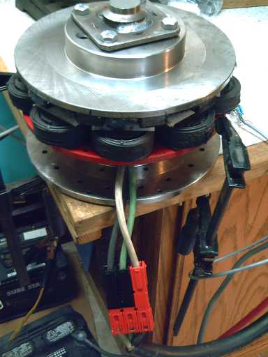
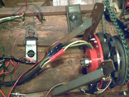 Testing EH motor on the new motor holding stand as a generator,
using radial arm saw and various V-belt pulleys to turn it at different
speeds.
A 6 diode bridge for the voltage, and a power supply for the magnet
sensors
to get the RPM, were required along with the meters.
To get the maximum current, I need to be able to put a
steady load on the motor and measure the current how hot the coils get
after a while, but someone good at math can derive the horsepower
(roughly) from the acceleration of the motorbike now being made, so I
won't need to know or measure just how strong that steady load is.
Some interesting specs are different currents and RPMs
measured on the same motor with the flux gap set to about .5, .65 and
.8 inches. The farther the rotor is from the stator, the lower the
current at a given RPM, and the higher the maximum free-spinning RPM
is. Naturally, the torque, and the horsepower at a given RPM are
reduced as the gap increases. Within limits, the motor has "adjustable
specs" with respect to torque and speed.
The "Adjustable
Specs Motor" table:
No-Load Current versus RPM with the flux gap set to three different
widths.
(@ 24 volt operation - I really must treat another
supposedly "worn out" old car battery
with sodium sulfate for use in the shop so there's 36 volts handy!)
RPM
|
Amps, Gap .5"
|
Amps, Gap.65"
|
Amps, Gap .8"
|
200
|
2.0
|
1.8
|
1.4
|
400
|
4.5
|
4.0
|
2.6
|
600
|
7.0
|
6.3
|
4.1
|
800
|
9.5
|
8.7
|
5.9
|
1000
|
(not measured, max RPM not measured)
|
11.6
|
7.7
|
1200
|
|
13.9 @ 1150 (max)
|
10.2
|
1400
|
|
|
11.9 (max 1440)
|
One interesting thing I
might try related to this is to
increase the gap in the EH outboard motor. This would up the RPM
somewhat, and so the boat would go faster - up to the limit where the
torque stops being adequate to get the motor up to the higher speed
under load. I doubt if going to an inch or beyond would leave a whole
lot of torque and power.
The present gap is roughly .57" and the maximum RPM is
about 1770 (at 36 volts). If I upped it to .75", it might well go up to
around 2500 RPM. On the other hand -- Ooh that's fast!
Note: More on performance testing is farther down... I seem to
have accidentally split the text into two areas, with considerable
duplication, and I don't have time to correct it.
Parts!
But low losses and high performance are only one part of
the equation. Motors
need to be affordable and practical. With the strengthened magnet
rotors - improved twice in
two months - and generally
improving parts and construction techniques in all areas, the Electric
Hubcap motor is getting simpler and faster to make, and I have
confidence that it is also
getting to be rugged and dependable to a degree probably unmatched by
other
axial flux supermagnet motors.
The improvements
lead to the tentative offering of parts to
help make the motors. Some of them (eg, the stator) can be CNC
drilled. I'll be offering stators complete with turned, welded bearing
hubs on a limited basis. Other labour intensive parts (coils,
magnet rotors) can
perhaps be made by people who might like to start their own little
business.
(Any volunteers living around Victoria?)
Hubs - Welding
My biggest remaining qualm was that the welded hubs hadn't
turned out to be as strong as I expected welds to be, owing to the
weakness of cast metal and especially after the heat of welding. If
pounded a bit, the welds would break where they met the rotor metal.
The
welds themselves also tended to crack during cooling, which appeared to
be
a separate heat stress problem - probably related to the cast hubs
shrinking when heated by welding.
I was thinking that perhaps there might be some better
part than the 1-1/2" pipe couplings to use for hubs. But on further
reflection, that's not where the welds had been breaking - changing
the hub wouldn't solve the
problem. Changing the rotor disks isn't practical, unless perhaps one
brand
proves to be notably better than others.
On consideration, I decided to try pre-heating the cast
parts, as suggested at one welding store with agreement by another that
it should be helpful. Perhaps that might pre-shrink them, or at least
be an advantage. I used a "swirljet" propane torch to preheat, and
though I couldn't get all that metal glowing red, it would have been
much more than warm. It was the best I could do at that moment. Then I
welded, using lots of stainless steel weld, all the way around the
circle.
That seemed to do the trick. I did two rotors, and
considerable hard pounding with a hammer didn't break the hub away from
the rotor or otherwise seem to have any effect on either of them. I
stopped short of probably breaking the rotor or hub themselves, or
seriously mushrooming the edge of the tenon, with the hammer. (One of
the rotors already had a minor crack, that probably
developed during the welding. It seemed unaffected by the hammering.)
Unless there are future problems, I'm calling the problem solved,
providing the preheating is used and the hub is welded all around with
the stainless (or special cast metal) welding rod.
Hubs - Turning - CNC Lathe?
Another small concern is getting the hubs lined up true
with the rotors so the rotors sit absolutely straight. With a clamp and
careful welding they're 'good enough', but ideally they would be welded
on and then the races would be turned, but I can't fit the finished
rotors onto the lathe. The answer to this must be either a special
plate that would allow finished rotors to fit onto the current lathe,
or a bigger lathe. (...and just where would I put that?)
Later I figured out a way to mount the rotor so the outer
face (only) could be turned after assembly. This has proved to be vital
as the hub, at the outer tenon end, so carefully turned to exact size,
seems to distort and
shrink a bit during welding, and the bearing races won't fit in. It
would
seem that the outer tenon can and should be turned after the rotor is
assembled. That should improve alignment. (Hub shrinkage also explains
why the welds are prone to cracking as they cool, and shifting
alignment during welding despite the hub being securely clamped to the
rotor.)
My latest thought for a solution to getting the rotors
onto the
lathe facing the other way, since I'll probably be doing a lot of
rotors, is to cut 1/4" off the lathe bed, thus making the 5" radius gap
zone just that vital little bit wider. Then nothing else is needed.
Now I'm thinking... A CNC lathe to turn the hubs
automatically
would be ideal. But isn't it just a matter of the tool moving against
the spinning part? That would mean a minimal CNC lathe could just be a
CNC
lathe tool turret mounted on any old lathe... even mine. In fact, it
would seem it may be just a matter of replacing two hand cranks with
stepper motors. The hard parts would be (a) getting the cutting point
set to
some "home" so it's moving from a known reference point relative to the
hub and (b) in my
lathe, there's some play in the threads: the position doesn't start
going backwards to the previous direction until this play is taken up.
That would make for uncertain positioning by the computer, which can't
account for that.
Rotor: Magnet Attachment Improvements
After having another magnet fly off a rotor in October I
realized
first that the epoxy glue I'd been using loses its grip after a couple
of years, and then further that something more than just gluing would
be best regardless. The problem was slight when the motors originally
were
supposed to turn with the car wheel, where they would never go more
than about 1200 RPM (at 120 Km/H on the highway with 13" wheels), but
it increases with the square of the speed. It would seem they want to
go up to somewhere around 2000 RPM when spinning freely. This time I
used a liquid epoxy resin as glue. Then I coated the whole
rotor and the magnets
with a thin layer of epoxy, which gave 'glue' around and going up the
sides of the magnets, rather than just a layer
underneath.
Still, I wrote last month that I wouldn't want to be
around if my 2000 RPM motors were turning at over 3000 RPM. At 3200 RPM
the centrifugal force would be 10 times stronger than at 1000; at
5000 RPM, 25 times stronger. But
these are being billed as "DIY" motors, and what people might do with
them in experimentation is unpredictable. Someone with no tachometer,
or unaware of the danger or not even knowing the motor specs, might,
eg,
boost the voltage to 48 volts or more and actually get it turning at
3000
RPM or higher.
Owing to this, and on general principles of strength and
durability, I decided the magnets needed to be attached even better. I
decided to do polypropylene-epoxy composite, and tried it out on the
outboard motor's rotor. "PP" cloth is lighter and
stronger than fibreglass cloth, and non-itchy. (Its great tensile
strength is why polypropylene is used for that rather coarse common
yellow rope.) Drawback
as a composite cloth is that it likes to hold its form and any creases
- it
won't lie
flat like fibreglass - it "floats up in the resin and so is harder to
work with". (It would also be
degraded by UV light, but what I found only comes in opaque black
anyway.) Although this information is on the web, nobody in town seems
to have ever heard of polypropylene cloth, much less has it in stock.
Unexpectedly, I seem to find myself at... well, near... the leading
edge yet again, even in such a 'mundane' area as 'fibreglassing'!
But at Capital Iron I found heavy PP strapping ("web") up
to 2" wide,
such as
might be used in
backpack straps, cargo straps, etc. Can't get more solid than that!
They had
it in both the marine department and the fabric department - same stuff
at somewhat different prices. (Aha!, it's true... boat owners
pay extra!)
I first planned to wrap a long strip around the outside of
the
rotor and cut slits in it, and fold the pieces over the magnets from
the outside edge. Then I would paste some around on the inside, slit
it, and fold it over the magnets from the inside. That would cover each
entire magnet and hold across much of the rotor surface.
But the PP strapping was too stiff to work with so easily.
I
ended up cutting a separate trapezoid piece for each magnet, and then
making an
aluminum form (x 12, with non-glueable polyethylene sheet liners) to
press the cloth flat against the magnets while
the
epoxy set. I put small pieces of steel on top of these, and the
magnetism pushed the aluminum pieces down firmly.
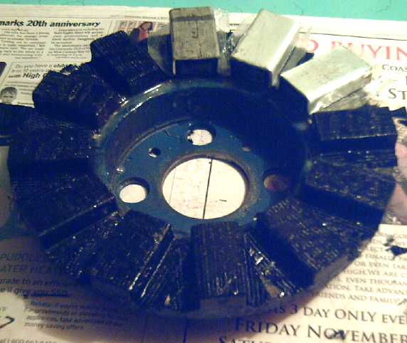 Covering the rotor with epoxy/polypropylene (re-enactment):
12 aluminum clamps (with polyethylene under to keep them from sticking)
held the stiff cloth pressed against the magnets
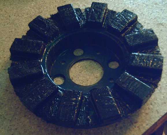 Finished Magnet Rotor (with another coat of epoxy).
Lots of epoxy and the polypropylene strap/cloth pieces overlap --
I don't think there's any chance now that any magnets will come loose
at
any sane RPM.
On December first I inadvertently got an EH motor turning
slightly overspeed (2300 RPM) myself, during testing of its specs as a
generator. I was glad for the solid assurance no magnets would fly off.
I think next time I'll try to leave more of the strapping's rougher
surface rather than have so much of it 'flooded' with smooth epoxy -
after all, golf balls have little pits all over because it actually
cuts air friction. (See the 'better windplant blades' article for my
idea of the 'ideal' texture.)
Magnet Sensors
The only other thing that's been bothering me is finding a
better holder for the magnet sensors, one that can be 'mass produced'.
...But never mind, as I write I've just thought of a nice circuit board
arrangement to bolt to the angle bracket mountings!
Later in the month I designed these boards in Eagle PCB
layout program, ready to send off the Alberta Printed Circuits along
with both types of motor controller boards when the A3938 board design
was ready to try, which it was on November 29th.
Coil Clamp Bar Drilling Jig
When Tristan got to the nylon coil clamp bars, I cut a
heap of them from a nylon sheet on the radial arm saw in a few minutes,
and I had
him make a jig for drilling the holes in the clamps exactly 1.5" apart.
Two thumbscrews clamp the work in place, and they just need to be
loosened slightly to slide it out by pushing the next one in. It worked
perfectly, and made it a snap to drill 9 clamp bars for the 9 coils of
a motor.
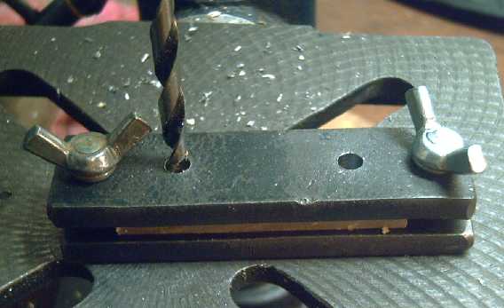
Drilling the nylon coil clamp bars with 1.5" apart holes jig
Later I found it was much faster to use a variable speed
(cordless) drill to turn the tap to thread holes, and I did it also
with the six #6-32 MOSFET mounting
holes in some heatsink bars. The cordless drill has adjustable "slip"
settings so it won't snap the threading tap if it's accidentally turned
too hard. This is a great production speed-up!
I used 3/16" nylon for the bars, but with a 1/2" flux gap
leaving
plenty of room, I may increase that on the next purchase to 1/4" for a
longer threaded thickness.
The reasons for using nylon bars to clamp the coils down
are:
1) Bars instead of just nuts prevent laminate pieces of the coil under
the nuts from breaking off, which allows the rest of the coil to slide
forward and hit the spinning supermagnets. (Experience! But the coils
that
did that also had a weakness around the bolt holes, now eliminated.)
The bars hold across the whole coil including the wire, so it would
have to break into little pieces before it would come unclamped - and
even
then the coil of wire would be held back.
2) Metal bars would interfere with the motor's electromagnetism and
decrease efficiency.
3) The nylon makes for a friction fit, providing "nyloc"
lock nut function so the bolts won't work their way out.
The bolts are placed left and right on the coils because that's the
direction of
magnetic thrust, so it holds the coils stiffest. Otherwise a
vertical bolts and a vertical bar (that is, pointing inside to outside
of the rotor) would be preferred for cooling air flow. (...a
single mounting bolt might let the coil twist and work loose.) Also to
aid
cooling it's just a bar, rather than a big round piece covering the
whole coil.
With the CNC drilled stator holes and the jig drilled
clamp holes both exactly 1.50" apart, everything lines up perfectly and
tightly with no custom fitting, hole edge filing, or need to drill
oversize holes, which multiply the hours of assembly time, as often
happens
with hand-drilled holes.
First EH Motor Workshop Student Completes His Motor
Tristan Money got his motor running on Thursday the 18th,
after
about 38 hours of actual working time during October and November. (Yes
I was keeping track.) He did everything including the welding and
the lathe work (which jobs I had pretty much expected to do myself),
except for a couple of painting
jobs that I did between sessions just so the paint would be dry and not
hold things up. The magnet rotor has the polypropylene/epoxy composite
shown above.
But now
there's the CNC drilled stators, preheating and defined better
procedures for
welding and turning the hubs (...or complete, ready to use stator
plates for those who don't want to weld), the strip lengths chart
and simplified assembly techniques for the coil cores, and the jig for
drilling the coil clamp bars. Sometime soon there will also be little
printed
circuit boards for the magnet sensors to simplify their wiring and
assembly.
I anticipate all the improvements together will likely cut
around 14
hours off
the building time for future motors, making it somewhere around 24.
If ready-made coils could be made available, they would
cut off another 7 or 8 hours, altogether cutting building time to less
than half. In lieu of some success at making nanocrystalline ceramic
coil cores (so far elusive) that are also economically practical, this
would be dependent on someone wanting to make coils to sell.
Tristan's motor on bench. 32 pounds; It ran great!
Turquoise Motor Controller: Designing for serviceability pays off!
I ran Tristan's motor the next morning to take a few
sample
readings, and suddenly it quit working. The problem appeared to be with
the motor controller. I opened the case and wiggled the control wiring
sockets, and the sound changed. Having made it integrated into a wiring
box chassis and easy to dismount the motor
controller side piece, I did so. There are just a few chassis screws, 5
heavy wires and two small plugs to disconnect,
and out comes the whole controller to troubleshoot and repair (or send
for repair), without disturbing the 'junction box' wiring to the
outside.
I unscrewed the small circuit board, and found two pins of
the controls socket had been left unsoldered when I made it. Of course
I thought that was the problem and looked no further. On reassembly and
reconnection, it still didn't work right,
but wiggling the plug now had no effect. The unsoldered socket pins on
the
circuit board could have caused intermittent problems, but in fact none
had
previously been evident.
Next I tried measuring voltages
and found that a pin in the motor power connector wasn't pushed home
in its socket properly and had come disconnected. When I fixed that the
motor did violent
things.
Then I measured some resistances and found there was a
short-circuited power mosfet. I took the controller apart again and
replaced
it. Since it was mounted to the heatsink and was connected with wire
and not to a circuit board, replacement was pretty simple. Everything
worked fine after that. The original problem was doubtless the
improperly inserted
power plug pin - it probably made a spark that 'took out' the mosfet,
as
it came disconnected while the motor was running.
Problems including blown components are more likely in
high power circuits than in other electronics, and the units are
usually more costly. At Canadian Electric
Vehicles I heard blowing controllers was common in new installations
owing to incorrect
connections. And in my experience, with poor connections in any of the
high power wiring. Once things are properly installed, trouble
is rare.
With most
motor controllers I suspect opening, troubleshooting, disassembly and
repair would have
been a much bigger job, and I had to do it 2 or
3 times, so it saved me some grief. With a construction that's hard to
disassemble, test
components, and access for repair, it gets to the point where you order
a whole new $500 (or whatever) unit -
and possibly more than once before the problem is debugged - instead of
taking a few readings and replacing a $4 transistor.
Motor Controller
Tristan did up an initial schematic for the A3938 motor
controller PCB. I fixed up or changed a couple of things and layed out
the circuit board for it, "Rev 1", finished on the night of the 29th.
In looking a bit further into regenerative braking, I
realized it's not done the way I thought, and it probably would be
complicated with a permanent magnet motor. With an electrical field
creating magnetism, the field voltage is increased to raise the
generated voltage ("back EMF") above the battery voltage, hence
charging them with the rotating energy of the motor.
It occurs to me that with the "adjustable specs" EH motor,
one could have in the brake mechanism a means to reduce the flux gap.
This would raise the generated voltage and induce regenerative braking
at higher RPMs (which is where the bulk of the energy is anyway).
But that would certainly complicate construction of the
motors!
The CNC Machine!
The CNC drill/router machine maker/owner asked when I was
coming
to do the rest of the stators on the evening of the 3rd, and we
arranged for the next morning, so I got ready to go over there and do
the two I had on hand, and since I was going, I wrote a CNC drill
sequence for the heatsink bars of the motor controllers and a jig to
hold them in place for drilling.
I did the rotors and bars, then we had lunch, and he said
(again)
that he didn't want to go to too much trouble adjusting it for smoother
operation since he had to move it somewhere - it was collecting dust
and
rust, little used in the unheated garage. And, again not for the first
time, he suggested an option was to move it to my place. This time, I
had uses for it and readily agreed. We took it apart and brought it
over in my station wagon and his van.
A couple of days later I decided where to put it - a
corner of the machine shop - and removed the prior furniture and drill
presses, and started setting it up. It takes up 1/4 of the whole floor
space of my shop (ugh!). I did a considerable amount of work
on it and spent some money on air line, plugs and switches.
Then I thought that having someone else's machine set up
in my shop was eventually
almost bound to prove unfair or troublesome to one or both of us --
either he would
gradually start to feel he
was intruding to come over and use his machine and I would essentially
'acquire it by osmosis' as time went on,
or he would find a major use for it himself and the frequent use
actually would have become intrusive,
or he would take it back after I'd invested my time and energy and was
using it regularly and was counting on it. So I bought the complete
machine
off him. The
investment was more than I've put out at once for any single item
besides property taxes in many years, and it pretty much wiped out my
meager bank accounts, yet it was doubtless a great deal for an
"industrial
strength" CNC unit that I already knew does what I need it to do.
I can now do a better job making prototypes where
precision is important, make motors faster and more accurately for
testing and evaluation, and also "mass
produce" certain parts for the motors and controllers - initially
pre-drilled stators and heatsink chassis parts - and put them
up for sale on the web site, to make building EH motors and controllers
easier for others.
Torque & Magnets (how many is optimum?)
Last month I wrote that with 6 supermagnets (2" x 1" x
.5") on the EH outboard's rotor I could prevent it from starting to
turn
even at full power with my hand. I tried it again with all 12 magnets
and I couldn't hold it back. (These tries were just with my hand on top
of the smooth rotor with nothing to grab.) I still think 18 magnets
would be
overkill, though, and have no plans to try so many again.
Unexpected Motor Current Measurements
Before I had the DC clamp-on ampmeter, I had no way to
measure higher DC currents. Measuring up to 30 amps earlier had
apparently "done in" my good multimeter's test leeds, causing
measurement problems later on, especially with some battery resistance
tests. I was taking the AC current flowing in one phase, as measured
with my AC clamp-on ampmeter, and multiplying by the square root of
two, per my BCIT 1975 Electric Power course notes.
This month, I tried measuring both the DC and the AC
currents, and I found the situation was wholly different than I had
imagined. I ran a motor spinning with 3 amps DC coming from the battery
per the DC ampmeter clamp attachment and checked the three phase
currents. Much to my surprise, the AC current readings averaged about
4.3 amps! According to formulas, there should either have been 2.1 amps
AC (with 3.0 amps DC), or 6.1 amps DC (with 4.3 amps AC in each phase).
What is the answer? Either the AC meter doesn't like
pulse width modulated square waves and its readings are out to lunch,
or else the AC current
isn't in phase with the voltage, and so the volts * amps, volt-amps or
"VA", doesn't translate directly into watts, where the DC current times
the battery voltage does. The latter idea would seem reasonable on a
motor with inductive coils, but the former seems indicated by the fact
that by changing the range on the AC meter, the reading changes: on the
0-20 amp scale, it says (eg - they fluctuate) 5.67 amps; on the 0-200
scale, 4.6 amps, and on the 0-600 amp scale, it just reads 1 amp!
Assuming then that the DC current draw figures are to be
trusted over the AC, I have some recalculating to do! Further specs
testing is regardless coming up.
Motor Testing and Performance Categorization
So far, I've built the Electric Hubcap motors and measured a few
things, but they haven't been properly measured as to efficiency, total
power, etc, except in vague terms or in certain aspects. Now someone on
a chat list has said I can calculate some of the specs such as
efficiency with a few readings and without much special equipment. And
Tristan pointed out that horsepower can be derived from knowing the
weight of his motorbike plus load, and timing the acceleration from 0
to whatever. Only maximum steady-state currents and power levels really
need some
sort of mechanical load in the shop, and a temperature probe to check
the maximum temperature of the coils over time.
But minimal equipment isn't no equipment! Last month I
made the second motor controller, for testing motors in the shop.
On Nov. 26th I made a motor holding stand from pieces of
angle iron so that the motors would sit still and securely while
running. It can be attached to a bench with my favourite bolt-down
devices: C-clamps.
Finally I drilled holes in a large V-belt pulley (a
'solid' sheet metal body pulley) so it could
be attached to a trailer (motor) axle flange or to a rotor, and on
December 1st I fitted it out and got it attached. This is to
allow an EH motor to be turned by another motor in order to measure the
generated voltage, which when a motor is running is called the "Back
EMF".
Later I plan to make another stand to allow two EH
motors to connect, and then one can be used as a test load, eg,
powering car headlight bulbs, to test the other's motor characteristics
under load.
To digress a bit into motor theory, the generated voltage
increases linearly with RPM, and is subtracted from the supplied
voltage. This
is why motors accelerate quickly to a certain speed and then run
steadily at that speed. If the motor runs at 36 volts and really only
needs 2 volts to keep it running at top speed, it will draw lots of
current and accelerate rapidly until the back EMF approaches 34 volts.
The motor won't go any faster unless it's pushed mechanically (as
below), in which
case, if the voltage rises above the 36 volts of the batteries, the
push starts generating
power that goes backwards, into the batteries, recharging them.
Below is a table of the generated voltages for Tristan's
motor, which should be typical, with about a .65" flux gap, at
different RPMs
obtained with the V-belt pulleys I happened to have on hand that had
the right bore size to mount the radial arm saw. The two low RPMs were
turned by hand to a ticking clock and readings are approximate. (One
could wish for a couple more in-between figures, eg 400 & 1500
RPM.) The voltage measured was the 3-phase rectified DC voltage. Since
the diode drop across the rectifiers read .765 volts on the meter, this
figure
was added to the measured readings.
The 2300 RPM reading is interesting because it's the
fastest any one of these motors has ever spun, and because the voltage
is
over 36 volts, so this speed wouldn't be attained with a 36 volt supply
- it would put charge into the batteries instead of drawing it out.
With a wider flux gap, the generated voltage would be lower and the
2300 RPM might be attained. A 42 volt supply would probably do it, too.
At 2300 RPM with the motor mounted on a stand and clamped
to the saw table, everything seemed quite solid and there was no
serious vibration or other problem. In addition to voltage, it
generated a feeling of confidence that all was as it should be.
Following these tests, I ran the motor with no load at the
same RPMs (except 2300) to find the idle currents. Perhaps only the 840
and 1040 RPM readings are reliably precise.
RPM
|
Generated VDC (diode drop corrected: +.765V)
|
Running, No Load: DC Amps @ same RPM
|
60
|
roughly 1.5
|
.5
|
120
|
roughly 2.8
|
1.0
|
840
|
15.1
|
9.4
|
1040
|
18.8
|
12.4
|
2300
|
39.6
|
Mechanical Torque Converter (MTC) Project
I had little time to work on this in November, but some
time to consider it. In the first rendition of the 'escapement' torque
converter, the original light escapements had provided little thrust,
but when just 100g was added to each one, their force was strengthened
by a
surprising amount. I had made the 25 'fan fold' drum rim, and
spots for
six escapements, but tried out just three. However, these ratios, 25 to
3 or 6, meant
each escapement provided its pulse
of force at a different time, and (obviously) non-symmetrically around
the wheel. But part of the idea is to provide enough force at one
moment to overcome any slack, inertia and static friction and start the
wheel turning and the car moving. It is then assumed that the next
force pulse will come
before it has a chance to stop moving again, so it will accelerate. So
having
one
escapement at a time provide a push probably wasn't a very good idea.
My next idea was to change the ring of teeth to a
different shape that would increase the inner diameter and allow 27
teeth that would fit the same escapements. That way, three teeth at
120º intervals would 'strike' at the same time. Although the
average force would be the same, the force at that moment would be
triple. I didn't get around to making this new ring. Then I realized
that it would put the teeth farther from the
center, which would mean drilling yet another six
escapement mounting holes, probably almost overlapping the previous set
and maybe at or beyond the outer rim of the rotor. And theoretically
the escapements
would be just a slightly different shape for the new radius, though
they were probably close enough.
While considering these complications,
it dawned on me that another way achieve the same thing - even
better - would be to change from six
escapements to
five, evenly spaced (72º) around the rim, and the spacing of those
would match the current tooth spacing
and all five would act in unison for a quintuple pulse of torque. For a
while I didn't want to drill the escapement
mounting holes, as some of them would have to be behind magnets, and
the drill
and threading tap would surely poke through and damage the magnets. But
on further consideration... too bad for the magnets - it's a prototype!
I'll spray some paint in the holes to seal the magnet alloy from the
air
again. As it happens, I even made just five of the previously intended
six escapements.
Hopefully I can complete this and try it out in
December. There would seem to be reasonable hopes that this version
will move the
car well beyond the "just barely" of the last couple of tests (I can
push it harder by hand)...
which are now at least a couple of months ago.
Quieter, Reproducible Blades for Windplants
Denmark gets 20% of
its electricity from wind and exports power surplus to its needs to
Europe on windy days. Even here in BC several windplant sites have been
or are being set up.
I've heard
that a
prime objection of residents to
nearby windplants is noise, and a small one deployed near here by the
city certainly makes enough air/propeller noise. The shape
of windplant blades is 'optimized' in cross section for lift, and
smooth, which
one would think would provide the least noise and the most efficient
operation... but does it?
There are indications of at least two ways to improve
the seemingly "no brainer" optimum designs. First, research on the
notched flukes of humpback whales has
pointed
the way to quieter, more efficient cooling fan blades incorporating
notches and
ripples. (This was on TV a while back.) Second, textured surfaces (eg,
the holes in golf balls) can have less air
resistance than smooth ones and may be quieter.
These ideas could both be tried and likely used to
advantage. A windplant blade akin to designs of fan blades with notches
or
ripples might be quieter, and I think a blade surface texture,
especially such as "pebbly" (I visualize sand
size and somewhat larger rounded surface bumps - varying random sizes)
would
also help air slip past and quiet them. Any such measures that made a
blade quieter would probably also decrease wind resistance and make it
more efficient as well.
As a production idea, tough polypropylene cloth or strap +
polyester or epoxy (resin)
could make lighter, stronger blades than fibreglass + polyester or
epoxy, would
be easy to
reproduce in a mold or jig (even with odd notched shapes), and would be
more durable than
wood. An opaque "sand pebbles" surface layer might be applied
afterwards (to also provide UV protection), or the surface texture
might be incorporated into the mold.
Perhaps a single blade could be hand made, and a mold cast
from it for duplication.
 First drawing of the design ideas.
(Date of conception is approximate - I added the text to the pictures
later, on the 20th.)
In spite of the intriguing possibilities I don't propose
to add this to my already extensive project list any time soon.
However, if anyone in Victoria would like to pursue it I would be
pleased to help give direction and support to the effort,
including typical blade profiles and overall windplant designs,
web
links and perhaps a lawnmower motor. There currently seem to be very
few sources for windplant blades
on the web (I only found one), and none for smaller, eg lawn mower
motor, sizes.
(Much less doing what are probably improved designs!) I'm not
sure if anyone has thought
of polypropylene-polyester composite construction either - perhaps not
a surprise
when the main fibreglass/plastic store in town hadn't even heard of it!
Pulsejet Steel Plate Cutter Project
I drilled out the telescoping holes, finished the floating
ball bearing one-way valve, and cut out most of the parts.
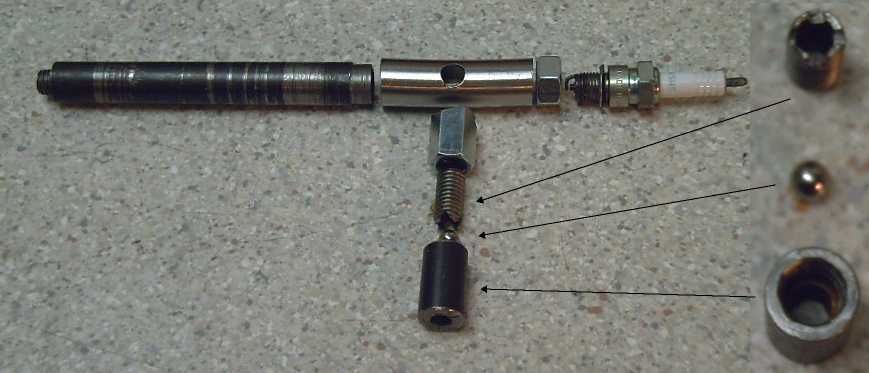 Pulsejet 'exploded' view.
L to R: inverse conical exhaust tube, main combustion chamber, nut
& sparkplug.
Lower, inset, from bottom, the one-way air intake: ball chamber &
outer (air sealing) stop,
'floating' ball, notched (air passing) inner stop.
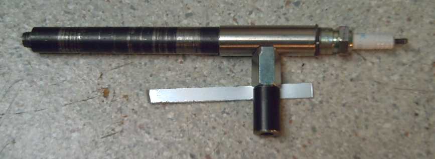 Assembled. Threaded exhaust (left end) allows for trying different
size nozzles.
Assembled. Threaded exhaust (left end) allows for trying different
size nozzles.
Then I welded them. I
burned a hole through the stainless tube by the spark plug nut, and
pretty much burned the "spark plug seat" surface off the nut itself, so
I cut the end off, got a new, thicker, nut, and re-did that. That
almost finished the main body.
Then I got busy with other things.
Remaining items were:
* a means to make the spark plug spark. There are a couple of ways that
this might be done. Tristan's motorbike engine yielded a spark plug
transformer, which itself now needs a means to activate it... but a low
voltage means.
* the propane connection. I picked up a .28mm nozzle with 6mm threads
for attaching it... to something. (I lost it somewhere and had to get
another
one.) I also got two 20 pound propane tanks someone had tossed in the
bushes on the boulevard, and a hose to connect the tank to the nozzle.
The outer end was a fitting with an outside thread that was
fortuitously the right size inside to thread for the 6mm nozzle.
* Some handle or way to hold it - pulsejets get red hot and more in
operation. One idea is to make a long handle that was also the propane
intake duct. Another is to put a long tube over the air intake - but as
that's threaded on, it might turn loose.
Electric Outboard Motor Project
The original guzzleine engine had worked with the prop
speed reduced about
2.75 to 1, because it ran at a high RPM (eg, 5000?) to get its 7.5 HP.
The Electric
Hubcap is a low RPM motor and at its maximum RPM
(1750) the
prop was spinning too slowly, because of the now counterproductive gear
reduction.
It's like having your car stuck in first gear - there's power to spare
for a truck, yet you can't get going very fast.
So the first task
was to fit a new propeller with a steeper
pitch. The steeper pitch prop
moves more water at a lower RPM. I
found an "11
pitch" Johnson propeller of the same diameter that looked like I could
make it fit,
propellers for the Honda evidently being out of production. I was told
the standard Honda one was "10 pitch", but the new one appears
considerably steeper - so I suspect my original was actually shallower,
perhaps 8 or 9.
It took a couple of days, but with some drilling, turning down and
sawing slots in a
shaft collar, turning a nylon "diameter matching fairing" (the prop's
diameter was
smaller than the outboard's) and other cludjing, it fit on.
Next was another water barrel test on Saturday the 6th.
With the first
propeller, the outboard had drawn 29 amps at 36 volts and churned up
the water "about so much" (for which the movie must be the record).
With the new one, the current rose only to 30 amps - but it did seem to
move noticeably more water. A little even slopped out of the bucket.
After the water barrel my motor making workshop student
Tristan
Money and I took it down to Esquimalt Anglers boat launch and took it
out in the sheltered harbor. On the 14' aluminum boat with two
passengers and
140 pounds of batteries (3 "size 27"), it drew 33 amps at about 34-1/2
volts (gradually dropping to 32 amps at 33 volts over the course of
several short
outings) at the motor's maximum RPM, 1740. That's 1100 watts, under 1.5
HP, and naturally with the motor loafing along like that the boat
didn't get up on a plane or even make much wake. The prop would have
been turning only about
630 RPM. But it did run well
and certainly moved
well above trolling speed. The heat sink bars
on the motor controller stayed completely cold to the touch. Once
I stopped on the water, opened the hood and felt the motor coils. They
were perhaps body temperature.
Tristan shot some videos with my camera, but not being
familiar with its idiosyncrasies, he didn't realize it was set to
"close-ups" and all the footage was quite blurry. (A couple of short
clips are nevertheless on
www.YouTube.com
- search for "Electric Hubcap Outboard"
there.)
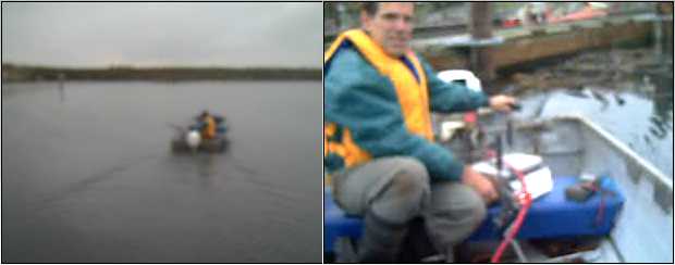 Images from the movie clips.
The motor controller (I'm turning the speed control) was clamped to the
seat.
Another movie details the insides of the motor.
The owner of the induction
motor outboard said they also
had had problems getting enough RPM out of the propeller. It
seems they doubled the speed of the motor in the
induction motor frequency drive controller - from 0 to 60 Hz (normal)
to 0 to 120 Hz (well above the motor's rated RPM specs, I'm sure). They
also placed the motor behind the drive
shaft, turning the shaft with a chain drive. The chain sprocket gear
sizes
also pretty much doubled the RPM again, so they had 4 x RPM increase to
counteract the built-in decrease (Yamaha 9.9 HP). Neither of these is
an option with
the PM EH motor, driving the shaft directly.
I looked at the gears of the outboard and saw nothing that looked like
it could increase the prop speed short of making different gears to
fit. Later I thought: perhaps I could, with more or less difficulty
(probably more - the two shafts were quite dissimilar), reverse the
gears. Then the ratio would be 1 to 2.75
instead of 2.75 to 1. At only 1000 RPM on the motor, the prop would be
turning 2750 RPM... assuming the motor could get it going that fast!
That would be like being stuck in fourth gear instead of first gear...
or maybe fifth, sixth or seventh? If it isn't geared too far in the
other direction, perhaps the
speedboat is in there yet. But it would be a difficult job.
I guess I should just look at the silver
lining: it's
solid, quiet, and will get you out to... well, I'm going to say it
(hey, it's my newsletter... you can skim over it!)
...to
where I've been hearing
the RCMP now lie in wait to levy big fines against those who haven't
kept abreast of the
latest regulations, bought the latest required gear, acquired a
"certificate of competency" to run anything over 0.0 HP, and paid
admittance fees to trespass on private BC public waters. This should
chase most
casual boaters off the water, which may gradually kill pleasure
boating entirely the same way provincial park use has dropped off
with pricey "day use parking fees". I think our governments want
everybody to just sit at home and watch TV.
I probably don't have the details entirely
right, but just the thought of probably being pulled over by the RCMP
almost as soon as I get out on
the water would have
dissuaded me from doing an outboard if I hadn't already invested a lot
of time
in the project.
That I am not alone in disliking such "big brother" overregulation
is attested to by the fact that, when only boats
with outboards over 10 HP had to be registered - just the boat
registered - by
far the most popular
outboard size for use on lakes was 9.9 HP. The government could have
inculcated safety consciousness and safer boating practices as well,
and
more easily and cheaply, with educational pamphlets placed in marine
and
water sport related stores, without creating a whole new odious system
of regulation and enforcement. It seems our governments try to protect
people from themselves by attempting to control them, passing
restrictive laws
that impact on everyone in unforeseen - and sometimes unseen - negative
ways, to control some minor problem caused by a few, instead of simply
pointing out better ways.
Our "tolerant society" of the latter half of the 20th
century has become intolerant to the point where using one's "freedom
of speech" plus honestly holding "politically incorrect" beliefs can
land you in jail, "zero tolerance" is even a slogan, and official
advice "Just say no." even shuns common courtesy - what happened to "No
thank you."? It seems to me we are gradually losing rights and freedoms
in every direction and edging towards dictatorship.
Naturally I wanted to test the EH outboard against the
induction motor outboard, on the same boat drawing the same amount of
power from the batteries. The tests were delayed by preoccupations of
the owner
of said boat and outboard, the need to scrub heavy marine growth off
the unused boat, not to mention by very cold
(for the coast: -7ºc) November weather.
A single set
of three 'deep cycle' lead-acid batteries should last a couple of hours
at the low 30 amps current draw. Two sets (280 pounds) might last five
hours.
Again I reflect on how lack of - and indeed sabotage of -
commercialization of
economical batteries has been sabotaging economical electric
transport. For more on that, read the next section, Battery News Behind
the Scenes.
If I get batteries using the NiMn-Mn chemistry working,
you'd lift a cheap maybe
30-40 pound
battery into the boat for the trip instead of a 30-40 pound gas tank -
and on the ocean another
one for a spare for an extra 5
hours reserve.
Turquoise Battery Project
Carbon Sheets
The battery project seems to hinge now on creating
impervious, conductive carbon sheets that won't deteriorate, to connect
the entire outer surface of the positive electrode briquette to the
positive terminal.
The traditional carbon electrode uses "pitch", evidently a
mish-mash of higher numbered hydrocarbons. In a store one day, I saw
"Diesel Kleen Cetane Boost". This is mainly hexadecane, C16H34. (or
more
precisely, an alkane - a rather heavy, acyclic, saturated hydrocarbon
string:
CH3CH2CH2CH2CH2CH2CH2CH2CH2CH2CH2CH2CH2CH2CH2CH3.) It came as a black
liquid in a plastic
bottle. (It may, or
may not, be some additives that make it a liquid.) Although pitch is
quite thick and the "cetane boost" was a liquid, pitch is also a liquid
- simply a very, very
viscous one at room temperature. It needs to be heated in hot
water on the stove to become workable: hexadecane (evidently) doesn't.
But the lighter alkanes such as methane (CH4), ethane (C2H6) and
propane (C3H8) are gaseous at Earth's temperatures.
Perhaps it would do the same job - without the heating? I
mixed a small quantity with graphite powder until it was a thick paste
with quite a low electrical resistance - x 10s of ohms; upper x 1s with
the electrodes close together. Then I rolled it out into a sheet
between two pieces of polyethylene with a "mini rolling pin" - a yellow
pencil crayon that was handy. (Another color might work okay, too.)
Oddly, the polyethylene, inert to so many things, started
curling up. So I transferred it to an aluminum sheet, and left it to
see if it would dry and harden or otherwise change. The smell indicated
something was evaporating. It would have to be considerably
dryer before I could try to compact it.
The next morning, the sheet had evidently dried
considerably and was cracked in several places. It wasn't hard, but it
had become quite crumbly.
I waited a couple more days, then tried to compact it. It
remained very crumbly. Then I heated it to 450ºF in the oven for
75 minutes. No noticable change.
It was just strong enough to get some ohmmeter readings:
as low as 2.1 ohms with the leeds close together, and under 4 ohms
anywhere to anywhere. Interestingly, the same readings were attained
whether the sheet was on aluminum or plastic, which would tend to
indicate that much of the resistance is at the contact points rather
than within the sheet. But pushing on the meter leeds harder would only
have broken up the sheet.
I think the hexadecane may be a good ingredient to add to
the
pitch as part of a mix, but it doesn't have the right characteristics
by itself.
Battery News Behind the Scenes & Editorial
I continue to
hear things about the lamentable state of battery commercialization
today and to give them thought. In battery news:
* I heard Michael Moore tell Larry King that 1% of Americans "earned"
(my quotes) 25% of the nation's total income last year. I'll
tie that in with
that university researchers found a way to produce nanotubes that
magnified the power density of lithium batteries tenfold.
The potential
value of this work to electric transport is zero: It
was patented, and Chevron has bought the patent, another corpse to add
to their
graveyard of
murdered battery technologies. No one will be able to
manufacture
transport size batteries using the advantageous new technology - they'd
be sued into
the ground. The 1% control the economy through such means.
* In India, Ni-Fe dry cells, made possible by research in 2004 at
Bangalore University, are now being produced in research quantities and
tested in applications such as telephone exchanges. If they perform
well, more than one interest has ideas about producing them to sell.
(We may well see attempts to suppress the new aspects of this
technology as well.)
* Europe may adopt Ni-Fe batteries as a standard to replace Ni-Cd,
owing to the toxicity of cadmium (and lead) and Chevron's suppression
of the green Ni-MH technology.
The
Ni-Fe's will last much longer than Ni-Cd's, too.
* Ni-Fe battery standards are being reviewed and reinstated by IEEE.
Evidently Exide
lead-acid battery company long ago convinced IEEE to drop the
standards. With standards in place, Ni-Fe batteries may be purchased by
telephone companies and others who have large needs for reliable
storage, which could increase quantities manufactured and reduce
prices. Even the original Ni-Fe cells Edison developed were
substantially better than lead-acid for electric transportation, and
"the 1%" played a substantial role in getting them off the market.
And here's yours truly's inevitable accompanying editorial:
Regarding the first
item: if Chevron (more correctly, the unscrupulous owners
of big oil and transport in general via any of their subject companies)
can seize
enough lithium battery
technology patents they may be able to stop manufacture of EV size
lithiums altogether. (Then they'll tell us that lithium is too scarce
to squander on batteries.) How do these people sleep at night, knowing
full well they're working directly against what the world wants and
needs? What does it profit a man to gain fortunes of money and lose his
own soul?
It shows how patenting
new transportation technology only guarantees it can't be used. How
long
will these greasy reprobates continue to bleed us all white and
sabotage non-petroleum transport before people rise up and demand the
changes to the patent system needed to rein them in - and, oh by the
way, perchance to allow inventors to get paid in some way commensurate
to their
contribution to society rather than to starve - the supposed but
non-functional raison d'être of the whole patent system in the
first place?
Big oil's sabotage
of superior battery technologies includes not only buying up patents
and
companies that try to start producing better batteries, and leaving out
the sodium sulfate
from lead-acid batteries in order that they'll corrode too quickly to
consider as being truly viable for electric transport, but also
strategically
spreading propaganda that blows the weak points of the best
technologies out of all proportion while staying silent on the good
points and on the fact
that lead-acid has many worse features. As there is no major organized
group with an interest - or even the knowledge - to
counteract these gross distortions of the facts - in effect lies -
they
get accepted as being true in everyones' mind, steering research and
potential manufacture away.
I'll single out two much-distributed statements about
Ni-Fe for
scrutiny:
"Nickel-iron batteries have a very high level of self-discharge."
"Nickel-iron batteries have a low charging efficiency."
Without qualifying context these over-emphasized
statements effectively
give the impression that the speaker must be experienced in the matter
and know what he's talking about, and that after a few days, at best,
the charged battery
must surely have little useful energy left, and
that it is very wasteful of electricity to recharge it. Is that
why Ford and Edison wanted to use it for their great new mass
production electric car in 1914? Is that why somebody went to a lot of
trouble and risk to burn all Edison's Ni-Fe battery factory buildings
down?
Rational
qualifications and comparisons -- that Ni-Fe's
charge dissipates only somewhat more rapidly over the weeks than
lead-acid's does, and that
it's only
marginally less efficient to recharge -- are never made. Furthermore,
the lead-acid battery
will start to corrode unless continuously maintained fully charged
(it's under charge, using energy, all the time when your petroleum car
is running!) and
it should only be discharged 50-60%,
whereas the
nickel-iron recharges good as new whenever it's next wanted (even years
later) and it can be discharged down to 'empty' with no worries. Also
not mentioned: a battery is most likely to be used within a day or two
of
charging rather than weeks later anyway - self
discharge is a very minor issue.
The overriding truth
is that nickel-iron (Ni-Fe)
batteries, notwithstanding certain weaknesses, are excellent
batteries that last for decades -- and they could be much better and
cheaper if the
designs and manufacturing techniques were updated. New Ni-Fe
developments virtually ceased when Jungner and Edison stopped
developing them a century ago until the above mentioned dry cell work
in 2004 in
India.
The industry has similarly
been kicking away to undermine nickel-metal hydride, notwithstanding
its recent excellent success - nay, because of its success - at
running
electric cars in California:
"Lithium is the 'holy
grail' of battery research." (We smell money! Forget everything less
costly than scarce lithium - we've bought the mines!)
"Yes, those
Ni-MH batteries worked great in the EV-1, but battery technology has
moved on." (Lithiums probably won't last 1/4 as long, and we can use
the high price as an excuse for not making and selling economical
electric cars.)
Actions speak louder than words: Is Chevron's hoarding
(via its puppet Cobasys) of all the patents it can lay its hands on
related to this "worthless",
"obsolete", "too expensive", battery technology, and their point-blank
refusal to
allow it
(in useful car battery sizes) to be manufactured, or to be imported
from
countries where they can't control the manufacturers, consistent with
the 'casually' publicized statements?
Ni-MH batteries are probably 20-30% better than Ni-Fe
overall and evidently of
similar super long life. They probably cost somewhat - but only
somewhat - more than
20-30% more to produce. More important, having the technology and being
able to manufacture and sell it - economically - with a
slimy
oil company
sitting on a stack of relevant patents, are two different things. Even
for small dry cells prices seem to remain fixed at or above 1000 $/KWH
even in bulk - too high to hook up hundreds or thousands of them
economically for an electric
car - instead of dropping below $500 and probably well below.
I keep seeing lithium AA cells in stores now. The whole
idea seems
absurd: the dubious advantage of lithium is that its high reaction
voltage of three volts (theoretically) allows greater energy density.
What is the point
to making it into 1.5 volt batteries? The energy density advantage is
wasted, and they cost more to make and won't last as long as green
Ni-MH cells. I may have a suspicious mind, but this would seem likely
to be a
strategy to quietly phase out the superior, very long life, green Ni-MH
batteries. to
gradually get
them
off the shelves, off the market, while spreading slander about them
that will poison Ni-MH in
peoples' minds and prevent a revolt. Then before the prohibiting
patents all expire everyone will have forgotten there ever could have
been an
economical alternative available, to (deliberately) crappy lead-acid
and to
(pricey) lithium.
Many of them also seem to be single use, non-rechargeable.
If lithium is so scarce, why is it being squandered in single use
batteries? Something's fishy there. And for all the boasting about
"lasting longer" on the packages, they never seem to actually say how
many amp-hours they hold. I bet it's less energy than a single charge
of a typical Ni-MH cell!
http://www.TurquoiseEnergy.com
Victoria BC