Turquoise
Energy Ltd. News #35
Victoria BC
Copyright 2010 Craig Carmichael - January 3rd 2011 - Happy New Year!
http://www.TurquoiseEnergy.com
= http://www.ElectricHubcap.com
Contents/Highlights:
Month In Brief
(monthly summary)
3 Years in Review
(a look back at developments: wave power, EH motor and car drive,
batteries, Department of Progress, other projects)
Electric Hubcap System & Motor Building
Workshops
* Metal Stator: had unexpected eddy current losses
* New Plastic Stator: molded composite of strong,
lightweight polypropylene
mat & epoxy
resin - non-conductive so no losses.
* Toroidal Iron Powder Coil Cores: Commercially made
"T200-26B" core is EH's exact size!
Will
greatly simplify making coils, boost efficiency and performance.
* Testing motors to
determine specs.
* Calculations with above improvements indicate EH motors
will attain 95% efficiency.
* Motor making workshop
price reduced with easier to make motors: $650 (Includes
parts/materials for
motor, $300).
* MC33033 motor controller deficiencies uncovered.
* Making new A3938 motor controller (some problems/adjustments
remain, but controller works).
* A3938's current limiting drive works differently to typical
PWM - and more like a gas pedal.
Torque Converter Project
* More mechanical torque converter theory.
* 5-Star Escapement Torque Converter: best design yet.
* Testing Problems: Motor controller deficiencies and sloppy
mechanical coupling to car wheel have been
hobbling torque converter tests.
* simple coupling change for next tests.
Turquoise Battery Project
* 9V battery disassembly shows simple yet exacting construction
techniques
* Ni-MH battery price reductions: for $200 I may replace my car
battery with 30 "D" cells. (If you want some Ni-MH batteries too, a
bigger order would get us better quantity discounts.)
* Latest Turquoise battery design overview (details here)
Newsletters
Index/Highlights:
http://www.TurquoiseEnergy.com/TENewslettersIndex.html
Construction Manuals for making your own:
* Electric Hubcap Motor
(latest rev. 2010/09/xx)
- the only 5+ HP motor that can easily be made at home?
* Turquoise Motor Controller (latest rev.
2010/05/31)
- for the Electric Hubcap. (Probably there are commercial
controllers that would work, too.)
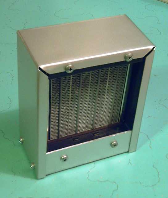
* 36 Volt Electric
Fan-Heater
- if you're running your car on electricity, you'll want a
way to defog the windshield and keep warm.
* Lead-acid batteries: Sodium Sulfate 4x
longevity additive - "worn
out" battery renewal.
* Nanocrystalline reflective rear electrodes to enhance DSSC Solar
Cells.(in TE News #28, 29)
* Simple Spot
Welder for battery
tabs, connections (in TE News #30)
are all at: http://www.TurquoiseEnergy.com/
December in
Brief
Thinking I had the EH motor design pretty much finalized
and having been given some motor equations and techniques, I spent two
or three weeks
trying to measure and derive performance specifications,
hoping to be done with it and move ahead on other projects. But some of
the numbers weren't making sense, and soon a fairly serious deficiency
I'd glossed over
came to light: the steel plate of the stator disk
was causing a rather strong electromagnetic drag load on the motor, so
the
no-load currents were rather high, reducing efficiency and overall
power out. I had expected the distance of the plate from the magnets
(over 1.5") would make this effect trivial, but it didn't.
Putting a 3/8" gap with pieces of plastic between the
stator plate and the coils helped quite a bit, but I wasn't very happy
with the arrangement. Then I unearthed the very first prototype EH
stator, 9 "reduced fill" iron coils cast in a polyester 'donut' ring,
and contrived to
couple it to a new magnet rotor, for the first time with no backing
plate. Now there was no steel except the coil core laminates, and it
was obviously better. With the steel plate, if you give the motor a
good
spin by hand, it stops in about one turn: electromagnetic drag. With
the plateless ring and partly unfilled cores, it would go about a
dozen. A few measurements showed the low no-load currents I was
originally expecting and
aiming at... but didn't actually have with the steel plates.
I decided a new stator design using plastic composites
(polypropylene mat and epoxy resin) would be
necessary.
So much for getting on with other projects! Being able to make a stator
of the exact shape and size I wanted would be an improvement, though.
The
motor is thinner, it protects the coils better (the wires stuck out
past the rim of the metal one), and it's also an end cover
of
the motor enclosure. It's also lighter, and the bare bones motor weight
is down to 25 pounds.
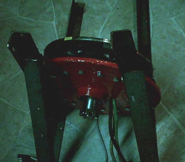 The new lighter, more efficient EH motor with the cast composite
stator.
The new lighter, more efficient EH motor with the cast composite
stator.
(Stator spray painted red with hi-temperature motor enamel.)
The old stator had gained some of its high efficiency from
a special "hollow" core. I also found a source for off-the-shelf
toroidal "hollow" iron-powder cores
of the exact right size and shape. Samples are coming. These will
not only improve efficiency, they'll make the coils, and hence the
motors, much easier to make.
Now no welding is needed to make the basic
EH motor, and the machined bearing hubs, now molded in, are easy to
make on any metal lathe - or for me to supply through the mail -
eliminating a prospective motor builder's need for a lathe. The coils
are also much faster and easier. Only casting the stator - probably -
takes more time than the extra turning of the hub and welding it to the
metal stator did.
I did get a couple of other
things done. One of
them was the small amount of work needed to finish the "5 Star" version
clock escapement torque converter. I took it out to the car and tried
it with the wheel jacked up, but I also took out the current probes now
that I had the DC probe,
and found out the motor controller wasn't letting the motor get enough
amps to develop more than around 1/3 power. In addition, I
finally realized that play in the coupling to the car wheel has been
robbing the wheel of receiving much of the force from the pulses of
torque the converters have put out. It's been
"hobbled" like that for all of the
torque converter tests from day one! When I figured that out I was
disgusted and I disassembled everything and took it all inside,
including un-installing the motor controller. The torque didn't feel
much greater than last time, but later I regretted not at least trying
to move the car on level pavement. I think now it's a very good design
- it might have done something relatively inspiring like take the car
across the parking lot.
Along with that, I started visualizing better more refined
designs for a similar torque converter that would last a long time -
this prototype is probably good for a few miles at best, seeing hte
aluminum dust it emits when it's going.
I burnt out the shop motor controller during motor testing
owing to a motor
short circuit problem, and I put together a PC board with the new A3938
motor
controller to replace it, which was after all on the project list. In
testing it, the
chip got burnt out and I didn't get it working. In light of that, the
controller from the car was needed for further motor
performance testing. More and better motor controllers are now assuming
a high priority. Tristan removed the minuscule dead 38 pin chip and
soldered
in a new one, and on the 31st the new controller was working, but soon
burned out again when highest current was demanded. Some adjustments to
the maximum allowed current seem to be needed.
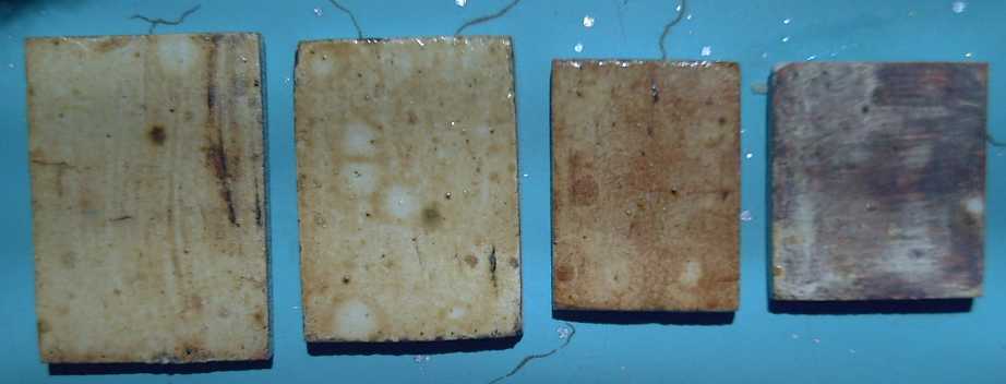
Another thing I did was to try baking another gooey carbon
pitch/graphite sheet, and I found out that if you cool the sheet off in
cold water, the aluminum that's glued solid to the sheet at room
temperature peels off relatively easily. Putting it
in
the freezer should work even better.
Being able to liberate the pliable sheet
probably makes it a workable electrode contact sheet, and probably much
the best
solution yet. Workable salt electrolyte batteries seem a good step
closer. However,
I didn't have time to try to actually put together a battery, much less
run tests on it.
3 Years in
Review
As I begin the fourth year of the Electric Hubcap and
Turquoise Battery projects, started almost from "Happy new year!" in
2008, perhaps a look behind is in order.
I started my 'green energy' inventive career by creating
some
designs to generate power from ocean waves in spring 2006, improved
over designs I'd seen in March, and as usual
in trying to create something new,
I got
enthusiastic lip service from some
quarters, incredulity and scorn from others, and no support at all from
anywhere. You would
think the government would enthusiastically assist, and businesspeople
would grab up, a new type of product that nobody else had previously
made, to be there first. But most of my fine inventions, even when
completed to at least a good demo state, have fallen victim to complete
indifference on the part of
those with resources to help develop, foster or commercialize them. It
seems instead like no one today believes anything really new is even
possible - no wonder the middle ages lasted so long!
However, I made a wave power test unit, and a generator with
supermagnets for it. I got
the idea that the generator would make a great electric car motor.
In January 2008, I decided to pursue the electric plug-in
hybrid
idea, and to make designs that could be made at home or in small shops
so that those who liked the ideas could do them as "DIY" projects,
regardless of the indifference of government or the hostility of
capitalists. For the
first time, great ideas could be published and spread via the internet
and anyone, anywhere, could access and use them. They could
spread despite my personal semi-poverty. Others better placed and more
business oriented than I might turn the inventions into businesses and
then fortunes, and electric transport would grow from the grassroots. The products I
was about to lavish my time and energy on wouldn't go to waste like so
many of my others.
I finished the proof-of-concept wave machine on the cheap
regardless,
but
mechanical defects prevented a successful test. Ironically, the
generator I'd made had heavy magnetic cogging and was part of the
problem. I substantially re-did
the mechanics recently and got a non-cogging lawnmower motor for a
generator, but since then I haven't had time to finish it up
and try testing it.
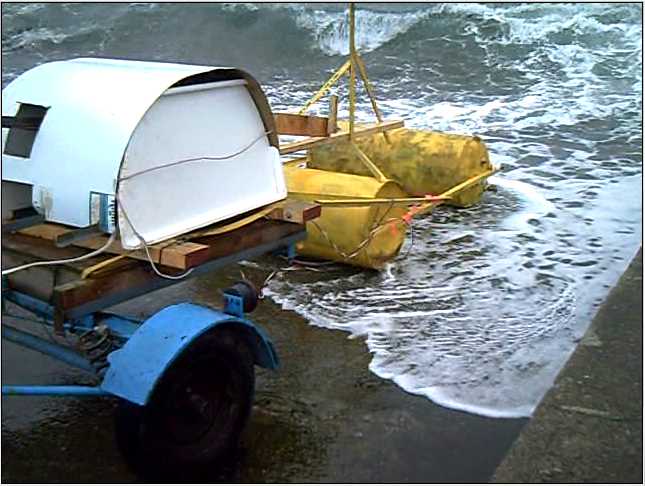 Dual-float wave power test unit with mechanics mounted on bouncy
trailer -
Dual-float wave power test unit with mechanics mounted on bouncy
trailer -
one of the sources of slack in the mechanism that prevented a
successful test.
As originally conceived, it seemed to me that
supermagnets, used
in an axial flux motor, should have so much torque at such low speeds
that it could drive a car by direct connection to the wheel, and so the
main
components of the system would be the motor, the solid state motor
controller, and, hopefully, some batteries that were better than
lead-acid. But though the first good motor - after some poor but
gradually improving prototype designs over the summer - moved the car
in October
2008, the torque was insufficient to be practical. It finally dawned on
me that it was actually
limited by the weaker field of the electromagnet coils, not by the
supermagnets.
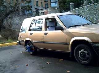 Car moving with directly connected Electric Hubcap motor, Oct 20th
2008
Car moving with directly connected Electric Hubcap motor, Oct 20th
2008
I made a better motor, but by spring 2009 it was evident
that driving a car would take something more than a fairly small motor
running at much too low a speed, and I got the idea of a
magnetic or mechanical torque converter. A workable magnetic design
proved elusive. The oscillating masses theory of mechanical torque
converters and workable mechanical designs
proved to be two different things (also for others who've tried
recently, though Constantinesco's 1926 design worked well), and it
wasn't until the last months
of 2010 I found a workable design concept - the "clock escapement"
inertial masses torque converter. Even then, continuing motor
improvements and tests, and other needs, kept the construction and
testing work down to a snail's pace and prevented a working design
until December 2010. It sits ready to test, a couple of hidden problems
that have been in the test setup all along having just been identified.
One
is 'fixed' for a prototype test, the other will soon be solved by a new
motor
controller using a more advanced motor controller chip (A3938), finally
working December 30th.
On that subject, when I started I didn't realize there
were off-the-shelf 3-phase brushless motor controllers, or chips for
the purpose, so I designed my own from six various logic and driver
chips. I proudly put the design on the web in the fall of 2008, only to
be shown the MC33033 controller chip. I made a new controller out of
that and it seemed great. But a few weeks later I got a message from
Digikey where I'd bought it, saying it was to be discontinued. From
somewhere (web search?) I found the A3938. It turns out the MC33033 has
some quirks, and I belatedly recognized them at the same moment that I
had designed the A3938 PC boards and was ready to assemble the first
one.
In the course of all this I tried a number of layouts and
finally hit on a double row format with the high power components
bolted to heat sink bars and hard wired, with the logic/gate driver PC
board for whatever controller was in fashion bolted on top with
'standard' wire connections to the power components. The bars couple
heat through to bars on the outside with fanned-out thin aluminum
roofing flashing heat dissipation fins clamped beneath them,
eliminating the need for expensive aluminum extrusions.
And I did a complete integrated aluminum chassis layout
wherein all the wiring related to the motor system started or ended.
The controller occupied one side wall and could be removed for repair
without dismounting the box and cable clamps, and the whole box is an
an extension of the heat sink. The transistors hardly get warm.
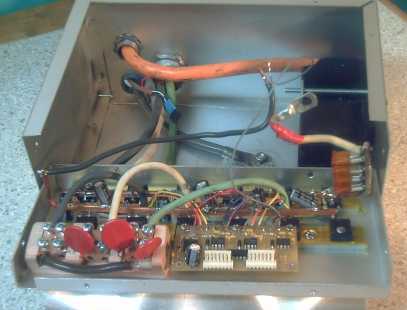
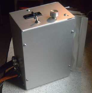 Motor controller with controls on the chassis, for testing EH motors
in the shop
Motor controller with controls on the chassis, for testing EH motors
in the shop
Concurrently with the car drive system, in early 2008 I
started trying to create nickel-metal hydride batteries that could be
made at home, after finding that economical NiMH batteries big enough
for electric transport have deliberately been made unavailable -
suppressed - commercially. But I also had in mind the possibility that
being
new to the
whole field,
"unindoctrinated" as it were, I might stumble across something great
that others
had missed. In my ignorance I started seeing seemingly great
'overlooked'
possibilities, some of which were impossibilities, but I became
convinced the
whole field wasn't very well explored and that there were much better
possibilities than any current battery technologies.
As time passed my knowledge of batteries
broadened, and my
electrochemistry ideas started coming into line with things that might
actually be possible. I was still trying things nobody else was.
By early 2010 I had the outlines of a fabulous battery
chemistry, novel techniques for doing vital but seemingly very
difficult parts of the work at home, and the outlines of an excellent
battery construction. It seemed I had solved nearly all the issues...
at least in theory.
I decided to use dissolved salt (KCl) electrolyte instead
of acid or alkali, as the average reaction voltages are highest,
including the overvoltages, and it's a fast electrolyte.
I created a way to make -1.4 volt manganese negative
electrodes work, which it appears no one else has ever done, by using
egg albumin to raise the 'hydrogen overvoltage' so it can charge - an
idea gleaned from an obscure piece of 1962 research. By comparison,
iron is -.9 and metal hydride is -.8, and manganese is lighter.
Instead of just nickel for the positive electrode, I put
in a mix of nickel and manganese. The manganese charges from Mn(OH)2
[II] to potassium permanganate, KMnO4 [VII], an astounding valence
change of 5 at +.9 volts for fantastic energy density. The nickel,
charging from Ni(OH)2 [II] to NiOOH [III] or NiO2 [IV], mainly adds
stability instead of being the main ingredient. Graphite powder
increases the conductivity of the oxides, just as with the cheapest dry
cells. A couple of other treatments also prevent the permanganate from
migrating.
Thus the battery's electrochemistry provides a fabulous
2.3 volt cell with incredible energy density from mostly cheap
ingredients (except for the nickel). They should be cheaper than
lead-acid and shrink them at least fivefold with even more weight
reduction - there's the real battery revolution!
The last and most thorny problem - perhaps more thorny
than the electrochemistries - was that with salt electrolyte every
metal I
tried
dissolves - oxidizes - in the positive electrode. The common dry cell
has the same problem and from its carbon electrode rod I finally
realized that carbon/graphite conductive sheets were about the only
thing that would work. Making such sheets and getting a battery that
truly worked properly was
elusive. Again everything came to a near halt in the fall as I grappled
with the motor and motor controller development, testing and
improvement issues, but
before the end of 2010 I had the concept for a somewhat gooey, pliable
carbon sheet that should solve the problems.
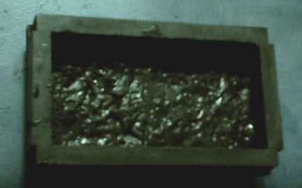 Conductive, sealing carbon battery layer
As time went by working for progress I began to realize
that the chief problems with switching to clean, cheaper, renewable and
non-polluting power, including for transportation, were not technical
but social. Existing, proven technologies that were known to work and
could easily do the vital jobs weren't being employed or further
developed. I identified two main culprits that are preventing us from
rapidly achieving the world of our dreams.
The first culprit was vested interests. In the last
century and more, a very small number of unscrupulous and manipulative
people have
exploited quirks in our social and political structures to seize
economic
power and build giant economic empires. These are, for example, the
less than one percent - and probably far less than one percent - that
"earned" 25% of all income in the USA in 2009. That only left 75% for
2010 for everybody else, and 75% of that 75% for 2011, and so on. These
parasites
control the multinational corporations as pawns in their monopoly game,
and they are sucking the life blood out of our economies. We are at war
with internal enemies we don't understand and only vaguely
glimpse, so they win most of the battles. These people like things just
the way they are, because they know any and every truly progressive
change is going act
to cut their power and influence, and they stoop to anything to prevent
change, including both using the legal system to their advantage and
violent crime if nothing else works. Many people vaguely sense that
something is wrong, but it's hard to put a finger on it. I personally
was oblivious until I started working on electric transport myself. The
documentary "Who Killed the Electric Car?" plus the fact that I
couldn't find the car-size Ni-MH batteries those cars used available
for any
price (much less a fair price), and
subsequently finding Chevron Oil has acquired 125 metal hydride patents
and killed the technology as far as transport is concerned, started to open my eyes.
Their supporters all the way down the line likewise
instinctively realize that their jobs, businesses and lives will be
changed if they embrace new things, and react against them. Perhaps
typical of this gut reaction is one local business owner - himself an
inventor and in some areas more progressive than most - to whom I
showed the sodium sulfate salt packages for quadrupling the life of
lead-acid batteries, who said "I sell ten batteries a week. Why would I
want this stuff on my shelf?" (Remember that next time you have to buy
a car battery from a smiling dealer!) The factories are all controlled
by the gangster "elite", and every automotive shop I tried sells
batteries. No one in the whole transportation industry wants them to
last longer, or wants better types of economical batteries to come on
the market --
only every consumer.
The other culprit was that there is no department, branch
or agency in government to oversee what is going on, correct problems
or recommend legislation to correct problems, and to work towards
desired change, to foster even the government's own stated long term
goals and the future on behalf of
citizens and the public good. All the departments are concerned with
today and the
immediate future. The effects of the errors in our governing systems
aren't being monitored. No recommendations are made to the legislatures
for fixing loopholes that hinder progress, and that allow power vacuums
to occur and to be filled by greedy and power hungry manipulators.
For example, the patent system has been routinely used to
kill priceless new transportation technologies for over a century. And
inventors usually have no means of
getting paid for their work, either while they work or after
successfully creating a new product or technology. (Less than one
percent ever get paid -- and even more rarely because they took out a
patent.)
The whole idea of the patent publication system was so that inventors
would get paid for their successful work, while their fine new ideas
could
spread rapidly to industry. It has never worked, and it has never been
repaired so that it does. Blatant abuse of a dysfunctional system
continues
unabated, the latest affront
(AFAIK) being the murder-by-patent of a fine new lithium battery
technology, years in the making,
just weeks ago (again with
Chevron as the "hit man").
In addition,
anything that seems too far off is dismissed by government as being
"too visionary", however simple it may be, for example wave power:
That's for the future -- it won't make money or solve problems starting
in the next year or two. No
action is initiated to traverse routes to proceed from the present to
the desired future, even when that future is a stated goal of the
government, and even though developing the routes may in fact cost
pennies today for future rewards of millions. And often that desirable
future
could be much nearer term than anyone thought once the needed
development effort is applied - look how fast everything changed in
world war two, all simply for fear the enemy might get it first. We can
progress in peacetime too. The answers are so often right in front of
us.
What is needed is a "Department of Progress" or
"Department of the Future", charged with dealing with such matters,
working towards the government's long term goals, fostering creative
endeavors if they are deemed worthy, connecting product development
with research and with industry, and making progressive
corrections to the procedures and processes where things aren't working
right.
I first started with an idea for an "Inventors Society"
which
might allocate funds to worthy projects, funded by the government. I
corresponded about this idea with my MP, which led to contacts with the
minister of finance, in which I conceived and developed the idea of the
Department of Progress. I elaborated on it and the reasons behind it.
Finally I realized that, in the absence of the very department I was
now proposing, there was no one in the chain of command between me and
the prime minister of Canada, so I wrote to him with a by now fairly
well developed idea, and urged him to appoint an able minister to start
the department. Unfortunately I have had only an acknowledgment that
the package was received. If he doesn't wish to be the hero, I may have
to send another package to his successor and even the successor after
that
until someone in power understands that there's a gaping void in his
administration - in every administration today - that needs to be
filled.
Along my way, I also digressed into a number of shorter,
seemingly simple projects, and also various techniques that could be
employed in installing the motor systems in cars.
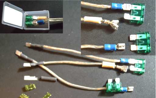
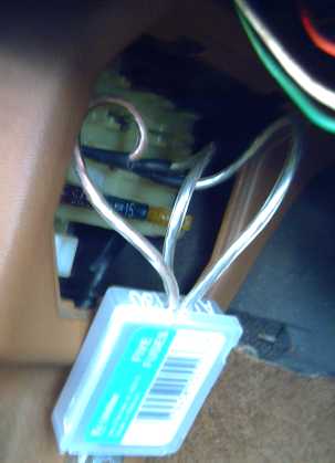
I found that by making a little fuse assembly one could
plug
terminal lugs the same size as fuse lugs into the car's fuse box and
re-route wiring as needed without changing any wiring in the car.
In particular, the turn signals could be run off "ACC" instead of only
with the engine turned on. That, probably an electric vacuum assist for
the brakes, and an electric heater-defroster, seemed to be the main
issues for running my own car with the engine shut off.
I made a 36 volt electric
car heater for the 36 volt
motor/battery system after seeing just one overpriced unit on the web
earlier. When I
had finished it, I searched again and found a number of choices for
lower prices. Perhaps I was wasting my time on that one!
I had an idea along the way
little related to energy: to create a web site where Canadians could
initiate informal 'polls' or 'referendums'. Currently governments claim
whatever they do is what the public wants, but there is no way to find
out what the public does want. Often those screaming loudest about
something are taken or mistaken to represent public opinion. Sometimes
these are just a small, highly opinionated minority. Other times they
are even organized vested interests with their own agenda, as when big
oil puts out one-sided propaganda and claim it comes from 'a concerned
citizens group'. Either way, they should not get their way by claiming
to be the voice of public opinion, and if the more polite silent
majority are allowed to speak, many things might start turning out
differently.
On DIY_EV_CARS@yahoogroups.com discussion list (which last
summer
mysteriously vanished without a trace -- could be innocent, but it fits
an all-too-familiar pattern for most anything to do with non-petroleum
transport), I learned that people were renewing lead-acid batteries
with alum. That sounded weird, but I looked up alum and found it was a
salt of sulfuric acid, which started to make some sort of sense. I
started experimenting, my battery work giving me some knowledge of what
I was doing, and I finally realized that sodium sulfate
was the
'correct' salt, diluting in the acid to sodium bisulfate, a sort of
acidic baking soda to perpetually keep the battery clean.
Alum, the first sulfate salt long ago found to work, also contains
aluminum or magnesium - 'impurities', and may
contain potassium instead of or in addition to sodium.
Battery renewal was
possible and good, but simply adding the salt to a new or near
new battery will make it last 3 or 4 times as long. I
worked out how much to put in. Of my four new or not-very-old
batteries that I added sodium sulfate to well over a year ago now, all
are still working great.
With sodium sulfate in my car battery, I've turned the
idle down very low - the battery is only charging when the car is
moving. Letting it run down a bit while waiting at red lights is now no
problem. This simple step has reduced my car's gasoline consumption
about 10%! (in mostly city driving.)
As mentioned, I found out that the battery
companies have known all about it for many decades, but they don't add
it to consumer batteries - the last thing they want is to sell better
batteries. I found some clever patents for impregnating it into
electrode separator sheets for the highest priced batteries. From there
it dissolves into the acid when the battery is filled. That way, no one
even in the battery
factory knows it's there except a trusted few.
 Sodium sulfate additive: battery load/cycling test
And somebody
mentioned nanocrystalline ceramic cores for motor coils,
and that they could be better than iron cores. With little knowledge I
attempted to create some in the kiln. I thought I could improve on the
most
promising results and find what worked and what didn't... but I got no
decent results whatsoever to improve on. (I think a reducing or oxygen
free atmosphere is probably required, which can't be attained in an
ordinary electric kiln.) I also tried to buy
nanocrystalline alloy core
strips, but e-mails went unanswered and I got no farther at that than
trying to make the ceramics myself.
But there was an unexpected positive result: in trying out
nanocrystalline glazes, I discovered I could make leaded borosilicate
glass
with transparent nanocrystalline titanium dioxide, which could be very
useful for a
reflective rear electrode for dye sensitized solar cells, improving
their efficiency by altering and reflecting back the light that got
through the dye, so it was more likely to be absorbed on the way back.
This could improve the efficiency of DSSC solar cells by at least 25%.
I haven't given up on this idea, but I haven't had
any time to develop better solar cells as they deserve to be developed,
either... or even to make a whole cell.
 Nanocrystalline borosilicate glaze DSSC reflector electrode
prototypes
Nanocrystalline borosilicate glaze DSSC reflector electrode
prototypes
I also saw videos of pulsejets in fall of 2010, and I
thought a small one might make a great steel plate cutter that needed
only propane and no oxygen. I started to put one together but only got
it half done before the motor improvements claimed priority over most
everything else.
Testing the motors this fall has led to considerable
improvements, including a composite stator of polypropylene mat and
epoxy resin to replace the steel ones. The steel turned out to be
causing considerable electromagnetic drag.
Motor with the new PP-epoxy stator (painted red) mounted on the test
stand
Then in the last days of 2010, I got a link to www.micrometals.com, who
it seemed actually made various cores of various powders and especially
iron powder. I downloaded their catalog and found a cheap,
off-the-shelf core
of exactly the EH motor's outer core dimensions. It was also a toroid
with a
hollow center, but I started to realize from one of the tests that its
shape seemed
beneficial as to flux lines and would have lower losses than a solid
cylinder, and that such an iron powder core should provide great
efficiency
perhaps equivalent to what I expected to get from the nanocrystalline
ceramics. Nine
are currently en-route to me to use in a test motor.
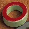 New toroidal iron-powder coil cores - same 2" O.D. x 1" tall size.
I started the motor project
(as well as the controller and the battery projects) doing most
everything either wrong or some needlessly hard way. After 3 years of
ongoing improvements, I've changed almost everything about the motor
except the supermagnets and the basic magnet rotor configuration,
having nine coils, and the basic axial flux layout with its resulting
'pancake' motor shape. Copper and core loss figures now lead me to
expect 95% peak motor efficiency with the latest exciting changes.
It'll be a very hard motor to beat - and it can be made at home!
Electric Hubcap System & Motor Building Workshops
A Motor problem and solution
I hadn't bothered to ground the frames of the motors -
after all, they're only 36 volts. No one would be hurt if there was a
short to the frame, and once the motor was mounted in a car, it would
be grounded through the chassis.
It turned out one motor had a short to the frame through a
coil mounting bolt, the coil having been mounted a little off-center,
which there was nothing to prevent. A piece of the ground wire of the
magnet sensors was bare (hey, it's ground anyway, right?) and it
touched the
frame of the in-shop motor mount. Zap! the coil voltage on the frame,
coming along the skinny ground line into the circuit board, fried the
motor controller. Absolutely nothing fries solid state circuits like a
voltage appearing on the 0 volts reference ground line feeding
virtually every component.
Now I'm specifying insulating sleeving over all the coil
mounting
bolts for all motors, I ground the shop's mounting frame to
the controller box... and I may put a small resistor on the circuit
board
feeding both the ground and the 12 volt supply wires to the motor
sensors, to eliminate or at least limit damage from a similar event in
the future. And if a motor isn't to be grounded through a chassis, a
fourth wire on the motor cable, grounding the motor to the
controller chassis, is probably in order.
Later it developed that the stator plates are to be
plastic. It might be a little tough grounding that, but no shorts will
conduct through it, either!
The new A3938 motor controller
In fixing the motor controller, it appeared that the
chips on the PC board were probably toast, along with a few of the
mosfets. Since I had just finished designing and having made the new
A3938 controller PCB boards, I decided that rather than make another
MC33033
board, I'd kill two ostriches with one brick and get the new design
working. But one ostrich tossed the brick back. The tiny chip
blew and I set it aside.
On the 30th, Tristan with his young eyes and fine
soldering skills came over and replaced the minuscule chip while I
worked on motors. Some problems
were found - a mistake in the schematic, and a backwards plug socket.
After some troubleshooting I figured these
out and got the new controller working. It worked great until a mosfet
blew for no apparent reason. After repairs the next day, it worked
again. I saw currents up to 35 amps during acceleration. Then I tried
to turn the control up quickly from a stop, and transistors blew again,
along with the chip. The current limiting should have prevented
destructive currents, but evidently there's something odd at work and
it needs to be set to a lower level.
The A3938's system of operation is interesting. To
compare: the MC33033 essentially provides a constant voltage dependent
on the input control setting. This means one must hold the 'gas pedal'
farther and farther down for faster and faster speeds. This is the
depth of push to go that speed, not the depth for a certain level of
power. But if the load is too high, the current limiting cuts in. This
simply cuts off the rest of each PWM cycle when a
fixed maximum current is reached. It doesn't drive the motor again
until the normal start of the next cycle, leaving however long an "off"
period until then. The switchover between voltage PWM and the current
limiting causes some weird effects, like sudden reduction of power. (I
discovered this as a cause of
low motor starting torque and low power that was going unnoticed in the
torque converter tests: all
the converters were being driven by a motor whose power input was being
stingily "rationed" by the controller. It puzzled me that a few times
in more recent tests, converters seemed to suddenly "take off" and have
surprising torque -- but only once the wheel was spinning, so it didn't
help get the car moving.)
The A3938 works on current limiting alone. A
variable maximum current is set by the amount of press on the 'gas
pedal'. When the motor current hits this value, the controller shuts
off, but only for a short, fixed period. Then it turns on again. The
"PWM frequency" varies in accordance with the current requirements,
dropping for higher currents as the "on" period lengthens.
Thus the average current can be much higher - almost to
the maximum limit, but without ever exceeding that limit (if it's
adjusted right). It seems like
a better system.
It's more like the gas pedal: the depth of push regulates
the flow of current - of gasoline or of electrons. With the current
being
regulated instead of the average voltage, the motor just keeps on
gradually
accelerating until the maximum RPM for the current or for the total
battery voltage is
reached.
Magnetic Friction!
In trying to determine motor performance I found there was
a big discrepancy between the DC and AC figures.
At 500 RPM, 36 volts times 3.0 amps said the motor was using 108 watts
of power... somewhere... with no load. But 6.8 amps squared times .064
ohms is only 6.0
watts of copper losses. Somewhere, it appeared 102 watts was being
eaten. I
found out where.
I already knew the motors stopped pretty quickly if spun
by hand, but not really why. After running some tests for a while, I
discovered
that although the coils
seemed little warmed, the steel stator plate holding them
was very
warm - even "hot"! Most of that 102 watts
of no-load
energy was going into heating the stator plate!
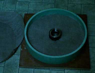
So I took an empty
stator (no coils but with bearing hub) and put it on an axle. I gave it
a spin
and it turned around about 40 times before coming to a stop.
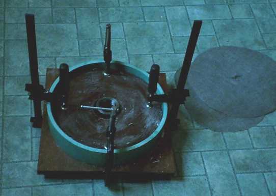
Then I put it on the axle with the magnet rotor, with a
1-1/2" gap. This time, it took only 5 or 6 turns to come to a stop with
about the same starting force. In spite of the considerable separation,
the magnets were slowing it that fast. I turned the empty stator plate
over, which resulted in about a 2-1/4" gap, and it turned about 12
turns, certainly an improvement.
The first thing to try would be to get the stator plate
farther away and measure the idle currents again. Presumably they would
drop significantly. I got longer bolts, dismounted the coils and
replaced them with 3/8" of flat nylon spacers stuffed under them,
adding that much gap to
the stator plate. This was a considerable improvement in no-load power
consumption, and the motor would spin 2 or 3 turns by hand. But now I
was sure it should be better yet.
Meanwhile, it occurred to me that the pancake motor
(minimum 2-1/2" thick in my original theoretical concept) was
already getting
fatter, with 1/2"+ flux gap. If I had to add another, say 3/4"
more
space between the rotor and the stator plate, it might be more like a
cake cake rising than a pancake! Was there a another approach?
Both the wide flux gap and the need to move the stator
plate back are a result of the large depth of field of the 1/2" thick
supermagnets. Thinner magnets would have a lesser depth of field.
That would mean both a narrower flux gap and a reduced effect from the
stator plate "only" 1-1/2" away from the magnets. As a bonus, the
magnets and rotors would be *somewhat* less dangerous to handle. On the
other hand, would this be enough magnetic force without going to 18
magnets?
I decided to buy twelve 1" x 2" x 3/8" magnets and try out
rotors made
with that magnet thickness. The 3/8" thick size
cost more than the 1/2", but the prices will come way down for whatever
the chosen size is when lots of the motors are being made.
Another technique would be to build the stator plates from
transformer laminates where they cross the magnet sweep. Fine for a
factory, but not for DIY.
Finally, one could make them from an insulating substance,
perhaps a high temperature plastic like bakelite or nylon. What would
that do to the magnetic fields? I decided to try this instead and never
took the pricey thinner supermagnets out of the shipping box.
Stator Losses and improvements
That seemed to help. I calculated efficiencies up to 68%.
It was still way below my expectations. But now the plate didn't get
very warm, nor did anything else, so it seemed there were no more
'outstanding' problem areas.
The 'best compromise' stator plate gap, between perhaps
1/4" and
3/4", remained to
be worked out. More 'radical' solutions were conceivable: the thinner
supermagnets will
give less depth of field. But that might mean less power from the
motor. They might well be better matched by shorter coils, eg 3/4"
thick instead of 1". Then a gap to get the stator back to 1" distance
might be required!
Or the opposite: thicker coils might be employed. This
would move the stator farther away, but the magnetized coil iron would
on average be farther from the supermagnets, again reducing the power.
But perhaps that's all thinking inside a box? Another way
to change everything, and just by making a
mold, would be to make a stator plate out of entirely non-conductive
material.
This would be the ultimate of low-loss materials.
Composite plastic stator with no steel backing plate
However! With this thought, it occurred to me that the
very first Electric Hubcap stator prototype had the coils cast in
polyester resin, a polyester donut ring like the windplant generators
it was originally derived from. Although the coils had minimal steel
laminates, I could run it long enough to measure some of its
performance characteristics to see whether the idea was great, not
worth
trying, or a 'maybe'. During the night of the 18th-19th, I came up with
a way to set it up: Turn a wooden piece to make a center for the stator
"donut", with a hole in the middle for a bearing hub, and turn a
bearing
hub to match. This occupied much of the 19th, but finally it was ready.
I gave it a spin by hand and it went a dozen turns (instead of
one with the original setup or two with the 3/8" spacers under the
coils). I used the hall effect sensors Tristan had wired up, removed
from their mountings and screwed to the stator. It wasn't perfect, but
it ran. Boy, did it run! I didn't need any more tests to tell me that
it was a vast improvement, but I took some readings anyway. The flux
gap was perhaps 17mm, a bit wider than in the earlier tests before
spacing out the plate (16mm), and considerably wider than the
13mm in the tests with the spaced plate. Reducing it would have
required more wood lathe turning, and with a new lathe setup.
Even allowing lots of room of error in comparing different
varieties of apples in the various tests with somewhat different coils,
wiring, and flux gaps, the figures seemed conclusive: It took about 22
watts
from the DC supply to turn at a steady 500 RPM instead of the original
108, or 72 with the spacers. The AC motor current (total) was 4.1 amps
instead of 9 or 10 amps. At 1000 RPM, it needed 52 watts instead of 259
(original) or 206 (spacers) and again the AC current was way down - 6
amps instead of 13 or more.
Here I thought again of the polypropylene cloth with resin
that made such a nice, strong cover for the rotor magnets - whether
used with polyester or epoxy resin. (It would take a lot of resin, and
epoxy is pricey.) As a bonus, the stator could be sized and shaped
exactly to suit. I wasn't quite sure about attaching the bearing hub.
It
could be done by welding a flat steel plate to the hub, say 5"
diameter, that the plastic plate is bolted to. But it would be nice to
figure out a way that would eliminate welding to the hub piece. That
would require that the center of the plastic piece be strong enough to
simply press in the shaped hub... or to simply press the bearing rings
into.
Another nice touch might be if the stator plate was sized
to cover everything and fit in or on the outer shell-ring, hence
forming the outer end wall of the motor. I went with this idea, and
with molding the bearing hub into the plastic. as part of making the
stator.
This led me on another quest for polypropylene cloth on
the web. Searches showed that it seemed to be used for everything and
present everywhere (including those re-usable cloth shopping bags) -
except for sale as cloth. A zillion third-party
advertising sites with no products of their own begging you to take
their useless links to nowhere utterly dominated the results. (Simply
saying ' -alibaba ' in the search reduced the number of supposed "hits"
by over 500.) Finally I found it's used as landscaping fabric and could
be had as cloth or nonwoven mat for low cost at any local hardware or
gardening store. The only problem was that the material isn't
identified on the package. The "landscaping fabric" could have been
made of fibreglass, PVC, rayon, or hemp for all I knew or anyone in the
store could tell me. It should be identified 'PP' for recycling
purposes if nothing else.
 Mold
Mold
 Laying sheets of PP mat in the mold
 Pressing the stator - PP mat and epoxy resin, with bearing hub in
the center, in the mold with plywood above and below.
Pressing the stator - PP mat and epoxy resin, with bearing hub in
the center, in the mold with plywood above and below.
I did the first ten layers of mat and the lower half of the hub, then
the second 20 layers and the top part of the hub later.
Later I finished by slopping on the rest of the thickening resin (kept
in the freezer 2 days) and spray painting with engine enamel.
I found that it took 30
layers of polypropylene
"landscaping" mat to get a 3/8" thick stator plate. When I got it
molded, it seemed considerably less stiff than I had hoped. It seemed
it would need 'ribs' at right angles to impart some stiffness to it.
But when I checked it again the next day, it had become very stiff and
seemed okay to use as-is. Perhaps a good idea anyway, but I'll skip it
for now - it's not vital. It's a prototype and the design may change,
which might make
any new jig immediately obsolete.
The amazingly light new stator, after discounting the cast
metal bearing hub which is molded into it, replaces the 6 pound disk
brake rotor with under 2 pounds of plastic composite. That should
bring total motor weight down to about 28 pounds.
 Stator before painting
Now it's tempting to think
of shaving off another 4 by
changing the magnet rotor to plastic as well, but the rotor's inertia
and solidity are needed for the torque converter and probably for other
motor applications.
The motor case outer barrel (whose 1.3 Kg isn't accounted
for in the current 32 pounds measure), could be lightened by a switch
from PVC to lightweight PP/Epoxy, saving at least a pound - even two by
making the wall thinner.
On the 30th I got the holes
drilled and assembled the
motor with the new stator and ran it with the A3938 motor controller,
also completed that day. Somehow, the bare bones motor weighed only 25
pounds.
New motor runs great!
I drilled the holes with the CNC drill program. I painted
the rotor with high temperature motor spray enamel. I'll also be adding
washers and a layer of tarpaper between the coils and the plastic
stator plate.
It seems excellent, so I'm now putting together another
one. In the middle of cutting out all those PP mat circles, it occurred
to me that if I 'marked' the circles with an xacto knife instead of a
pencil, it would save a lot of snipping with the scissors. I zipped off
another 18 circles that way in under 15 minutes. By the nature of
molded composites, I can probably use the (PP) bag of PP mat scraps for
another stator, too.
I've also turned the bearing hub, so It's ready to mold.
The first bearing hub wasn't quite straight though (I'll even the gap
by adding washers under each coil to suit), so I'm trying to come up
with a good jig to hold it perfectly centered and straight.
Powder Cores
I'd been wanting to find a way to avoid having to piece
together those cores of nail gun finishing nail strips - they add a
serious amount of labour to making a motor.
In talking in a discussion group I learned a bit more
about powder coil cores, and there was a link to micrometals.com, who
appears to be (or to own) the chief manufacturer of ready-made cores of
various
compositions. I downloaded a catalog, and discovered that although
there was no cylindrical powder core around the EH's 2" diameter and 1"
length, there were toroidal cores of exactly that size, "T200". I
decided that a big hole in the middle of an otherwise perfect core
shouldn't stop me from trying them out.
I phoned for technical assistance, and it sounded like the basic "26"
iron powder would be, though perhaps not the ultimate in permeability,
high saturation and low loss, a good compromise - quite serviceable and
economical. (And doubtless better than the nail strips.) I was asked
if I wanted a couple of samples of 26 and a couple of 52, which had a
little higher permeability. I said I needed 9 to make a motor. He said
he'd send 9 "T200-26B" cores. It turned out these are only $1.88 in
single lot pricing. I wouldn't be ordering less than 50's (only 5
motors worth), I'm sure.
If these work okay - and there seems no reason to
doubt that they will - the coils will be far easier to make. I envision
mounting the core on the coil winder with 3" diameter non-stick plastic
side 'washers' to hold the wires in place, mixing some epoxy and
winding all nine coils in well under a couple of hours, painting the
epoxy onto each layer of wire as it's wound. I might wrap a layer of
polypropylene around the outside. The entire coil would be dismounted
from the winder chuck complete with the center bolt that holds it
together and left for the epoxy to set, and there'd be nine sets of
winders to do all the coils with the same batch of epoxy.
An additional, and large, benefit is that the powder cores
appear to be very efficient (the manufacturer's specs are in the
catalog), where the nail strip cores were "good enough" but had
significant losses. The composite plastic stator and these cores
together with the other design advantages should boost the EH motors
into the singularly ultra-efficient (95%+) category I didn't previously
dare hope to achieve.
There's one more twist: Considering the magnetic
interactions, the toroid form of coil core may actually perform
better than a solid cylinder. The copper will magnetize the core in
an area more concentrated towards the sides - closer to
where the lines of force from the magnets actually are as they approach
or leave the coil's
vicinity. When the magnet pole is right over a coil, that coil is
turned off
anyway. And, the hollow core has 40% less iron to have iron losses
from. As long as the 60% iron that remains doesn't saturate, that's a
further considerable efficiency boost.
As an additional bonus, the toroidal cores will weigh only
220 grams
each where the
laminates weigh 265 plus whatever the motor varnish adds. The motor
will weigh about another pound less. Bare bones, the motor to
drive a car (now just 24 pounds) will weigh about the same as a typical
mounted 13" car tire.
The one thing I think I
need to watch is that evidently the iron powder cores are only good for
70ºC, so there's not a lot of point using high temperature motor
varnish to allow 150º or more. (In fact, baking varnished coils in
an oven at 225ºC with 70º rated cores seems like a very bad
idea.) I
will use a high temperature rated epoxy, though. If temperature does
prove to be a problem, they have the same toroid cores made from higher
temperature
spec materials. A motor that can go up to 175ºC can run at higher
power
longer than one that only goes to 70. On the other hand, the ultra high
efficiencies will make this a very cool running motor, so 70º
parts may well be just fine. And
with the toroid shape, cooling air gets to the inside of the coil as
well as around the outside. The polypropylene stator's epoxy is also
only good for
70ºC, but the coils will be mounted slightly off it with tarpaper
and washers, which again allows cooling air under the coils.
$1.88 each, super
high
efficiency and performance! ...and all that work I did earlier trying
to make
nanocrystalline ceramic cores! The professionally made iron powder
cores have very low losses per cc at EH motor frequencies, and the
toroid form would
appear to reduce cc's and further increase its efficacy, probably
accomplishing as
much as I had hoped to get with the ceramics. And they'll also
accomplish the other vitally important part of the job: making the
coils, and hence the motors, way easier to make.
Motor testing and performance categorization
I did considerable measuring of Electric Hubcap motor parameters in
late November and the first part of December, and
through the wonders of math and equations came
up with some seemingly bizarre and highly suspect figures for
efficiency and power (which also resulted in the plastic stator
mentioned
above). I've heard brushless motors can have "over 90%
efficiency" and had high expectations, but I wasn't seeing anything
like that for the EH motors. Here I thought I had created a great
motor, and I was embarrassed to find I was calculating efficiency
figures
like 55%
and even 45%.
My test setup was primitive, and I only tried a couple of
(unknown) loads at few RPMs, usually 500, 1000 and 1500. The "load
tests" were done by pressing my foot against the spinning rotor and
increasing the 'throttle' until I read some considerable DC amps coming
from the battery to maintain roughly the same RPM. Other
than being unsteady, providing no torque readings (to compare with the
theoretical), and the smell of burning
rubber from my running shoe, it seemed to work okay. It was expedient
but
not elegant.
But upon reading more 'stuff' on the web, I started
realizing some things that were good to keep in mind. The first was
that efficiency was so high only under the best conditions, and that
motor manufacturers evidently usually
rated their
motors at the peak point of efficiency: at the ideal high RPM and light
load. (Why
wouldn't they?) I found a document and graph that showed more real life
conditions:
 Sample: performance graph of a small commercial DC PM motor.
Efficiency is highest, 75%, at very low torque, eg 10% of full.
At the highest output power - at about 1/2 speed, 1/2 torque, 1/2
current
- efficiency is 47%.
(Source: http://www.micromo.com/n390432/n.html)
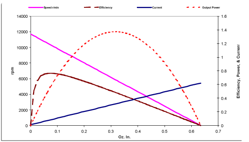
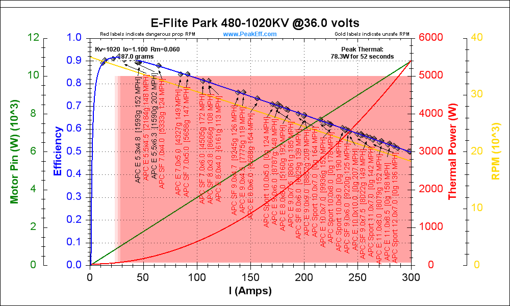 Later I found this performance graph,
probably the most similar graph to what's now expected from the EH
motors except for RPM range.
It's a 36 V brushless DC PM model airplane motor (with just .06 ohms
motor resistance!).
At very light output power the efficiency is 92%.
At very high power where push tries to shove, it's just 50%:
almost 11000 watts in, under 5500 watts out.
EH operation will be restricted to the left half of the graph - under
5000 watts in -
with 95% peak efficiency, dropping to 75% at full load.
After seeing the graph and accompanying stats, the figures I was
getting began to look more
understandable - and reasonable.
At no load, a motor's efficiency is de facto
0% - whatever energy is used is used just to keep the motor
spinning. On the EH
motors, the current at no load with a steel stator was high enough to
prevent approaching great efficiency figures at light loads. At high
loads, the same extra current becomes part of a heavier I^2
loss figure, causing considerable extra copper
resistance
losses. The EH with the new PP/epoxy plastic stator is much more
satisfactory, and with the iron powder coil cores it will attain the
highest possible
efficiency standards.
Another problem was that "power in" is
battery volts times battery amps, and the DC current clamp was wildly
off at low currents and still reading 15% high at 10 amps, above which
point I have
to pull the Fluke DVM amp meter out of the circuit before it fries
(which is why I bought the clamp in the
first place), so
I have no other comparison.
Also
someone on a list said that with PWM you had to use meters with a high
bandwidth - that low frequency meters could read "wildly" off -
possibly
the problem with the DC (& AC) current clamp, although it also
reads higher on AC currents compared to the other clamp and to the
Fluke
meter on amps. At first I was
also just assuming the battery voltage was 36 volts, but at high
currents it was often under 33 volts - 10% lower. Power out is
calculated from the
motor AC amps times the torque constant times the RPM: it doesn't care
about the DC supply. If the figure for power in is, eg, 20% high, and
the output power figure is right, then an efficiency of 95% reads as
75%, and around 55% comes
out as being around 45%. The error is further compounded if the AC and
back EMF readings are on the low side. Without a motor load that will
tell how much torque the motor is
actually producing, I have no good check that the Power Out side
readings are consistent with the
Power In side.
I have an idea for a magnetic brake to give me this load:
take
an EH magnet rotor and get it near to the rotor end of the motor, in
line with it. Put a 2 meter long stick on it, sticking out 1m each side
- balanced. The magnets will attract to the back of the rotor and will
try to spin with it, but this rotor can't spin because of the sticks.
Put a weigh scale under one end of the stick. Each 102 grams the scale
weighs is one newton-meter of torque the motor is putting on the rotor.
An aluminum plate 'coupling' near the load rotor magnets (spinning with
the motor rotor) may work best, and will drag but not grab to the
magnets. Adjusting the gap adjusts the loading.
Having the essential idea and taking the time to figure out all the
construction details and make it may however prove to be to different
things. Without even looking it up, I doubt I could afford a ready-made
test brake.
Another person has suggested a simpler "prony brake",
simply
an adjustable circular clamp around the rotor with an arm sticking out,
with a scale on the arm as above. The work done heats the brake, so it
may smell as bad as the running shoes.
While having no figures for other motors of similar size
and construction to compare with, and figures of suspect accuracy for
the EH motors, after some weeks of all these frustrating
measurements, calculator banging, and frying a motor controller, I had:
a) actually improved the motor's efficiency by changing to plastic
stators, and made it more reliable by putting sheathing on the
coil bolts. (Now the sheathing will be made redundant by the toroid
coil cores.)
b) found that now nothing was getting even very warm, indicating there
were no more exceptional losses (and certainly saying nothing bad about
the
magnets as cooling fan blades - you can feel the air they blow).
c) a bunch of actual performance figures and calculations, done in the
first half of the month. These were to follow on next, but the change
to the plastic stator, not completed until after Christmas, makes most
of them obsolete, and the new ones will soon be obsoleted by the iron
powder cores. Hopefully I'll have some excellent figures next month.
Performance measurements and calculations
One calculation isn't rendered obsolete by the changes:
The coil resistance between motor terminals is a
crucial
parameter and measurement, and I measured it with a power adapter to
supply a small
power across the coils. The measurements were plugged into R = E / I:
.070 V / 1.10 A = .064 ohms... virtually the same as the
calculated resistance
based on tables of the resistance of #14 copper wire, the coil
connections, and the lengths of wire in the coils. Evidently one simply
measures the resistance between any two of the three terminals to get
"Rm". They all read about the same, but what happens with the third leg
when you only measure across the other two, is unspecified. Should the
resistance be multiplied by the square root of two like the current...
or should it be divided by the root of two because the legs are in some
sense in parallel? I think
and infer that one just uses the actual
reading, but it would be good to not
be left guessing about these
things!
I also think the EH motor is best here: lower than others
of the same
power and size because of the round 'donut' coil windings, magnetizing
the most
nearby iron, in closest proximity to the rotor magnets, with the least
length of
copper wire. The resistance would have been .072 ohms for square coils,
and more on
standard coils with "overhangs". The copper
losses - the biggest efficiency loss - are directly proportional to the
resistance -- motor resistance
times the square of the current.
95% Motor Efficiency
The
change to the plastic stator, and the coming change to iron powder
cores, pretty much blots out the meaning of most of the
figures measured earlier, except insofar as those figures actually
prompted those
improvements. Supermagnet motors often peak at over 90% efficient and
axial flux is the best, and we can calculate or estimate the following
factors that will make the Electric Hubcap's newest design better than
others:
* low loss iron-powder toroid cores that will also put the
maximum magnetic flux right where
it's needed.
Eddy current losses in powder cores are trivial, only the
hysteresis losses being significant.
Iron losses, based on the manufacturer's printed specs,
will be only about 10 watts at 1500 RPM.
* the new composite plastic stator eliminates most of the magnet rotor
drag caused by metal parts
Only internal nuts and bolts, and more distant mounting
hardware, remain.
* the wide (and adjustable) magnetic flux gap is known for high
efficiency (the axial flux advantage).
It also prevents gradual demagnetization of the
supermagnets, making the motors 'everlasting'.
* The lowest coil
resistances attainable for the voltage and size, .064 ohms.
At low loads, the copper losses are again only 15-20 watts
at 1500 RPM.
The total no-load losses at 1500 RPM will thus be only 10
or 20
watts (Cu) plus 10 watts (Fe) plus bearing friction plus air friction,
just a few
tens of watts. By contrast, they rose to several 100's of watts at that
RPM with the steel stator and nail gun strip coil cores.
15 or 20% load is likely to be the most efficient range.
15% load is 700 watts and losses should be only about 35 watts, so it
seems we can expect 95% peak efficiency. At my intended
maximum watts, about 4600, 75% might still
be attained, where other motors show graphs dipping to 50% or less at
their maximums. This is partly the built-in efficiency, and partly
that I'm limiting the maximum power to the best operating area so as
not to
generate too much heat or drain batteries needlessly quickly. (The
second graph above ("E-Flite") would also be minimum 75% efficient at
full load as shown if they limited full load to 150 amps of current.)
Mechanical Torque Converter (MTC) Project
More Theory
The oscillating masses torque converter is something like
a rotary version of a hammer
striking a nail. There is a longer period where kinetic energy is
gained,
the down swing, and then a shorter period where that gained energy
moves the load: hitting the nail.
In the torque
converter, the energy is imparted in such as way as to not stop the
motor each time but only to slow it a bit so the rotary motion can
continue - a 'glancing blow' or slip, which may either be a sudden
'impact', or
a relatively rapid but non-instant change.
Like simply pressing a hammer against a nail, the average
torque
of the motor isn't enough, eg, to start a car rolling up a hill. But
that average is divided into longer periods of little or no torque, and
shorter periods where that accumulated energy is spent to produce much
higher torque. The high torque hit starts the car moving, and each
subsequent hit gets it moving a bit faster.
In this, one must consider the periods and magnitudes of
the forces. If
the unit were, for example, to have a 20 second period to build up
momentum and then a 2 second period where that built up force is
applied to turn the wheel, no one would question that the car would
start moving, and indeed it might well be doing 'street speeds' after
the
two
seconds was up. But to store up this much energy the unit might have to
do something like
start a massive flywheel spinning and then let out a clutch to
engage it.
If on the other hand the unit had just 20 microseconds to
build up speed and then 2 microseconds to dissipate it, perhaps all
that would be noticed would be a high pitched vibration. The minuscule
stored force would be averaged out with the same effect as a steady
force,
perhaps too little to start the car rolling. On the other hand, no
heavy parts would be needed to hold the minute, short period energies
generated within such a system.
Something in between is needed. The smaller the forces and
the shorter their time periods, the tighter everything has to fit. At
some point, even the rubber tire will absorb the tiny torque hits and
present to the road the average, too small, force. We need forces of
sufficient magnitude and length of period that the car actually budges
with each hit of torque, but not so large and slow that excessive
masses have to be employed, with the car moving in perceptible lurches.
Hidden torque converter testing
problems
I've become aware that there are at least a couple of
problems in the torque converter tests that aren't the fault of the
torque converter.
The first one is the coupling between the torque converter
output rotor and the car wheel. A while back, I made a plate for the
car wheel with four 'extra' holes and some tapered pins for the output
rotor that would fit into them. But when I changed from the smaller
steel drum to the 12" aluminum drum, those pins didn't fit and I used
four 12mm bolts. They fit in the holes, but there's a lot of loose
play. I can see it in the videos I've taken: The
output rotor bounces back and forth relative to the car wheel, when
they should move as one. The
escapements must 'hit' the output rotor, but then
the bolts hit the edges of holes in the coupling to the wheel, then
bounce back. Larger, longer
period torque hits than I hope to employ would be required to overcome
all that slack. (The new "5 Star" escapement converter design has
the strongest, longest period escapement hits so far.)
On the 23rd, I took the plate off the car wheel and set it
on the converter. On looking it over, I realized it could easily be
made to
work. I had in fact drilled 12mm holes that just fit 12mm bolts. The
original sloppy, oversize holes were coupled to the converter. If I
simply bolted the plate tightly to the wheel using the oversize holes
instead of the small ones, the small holes would be left for the
pins to the converter, and the play would be virtually eliminated.
The second problem I discovered on the last test, on the
15th. On a whim, I took out the AC current
probe and the new DC current probe to check the motor currents.
(...along with all the heavy things I have to lug out and set up for
each test.)
Much to my surprise, the highest the AC motor current
readings got was 40 amps, and the DC supply 25. I've seen 80 amps AC on
the same motor with my original motor controller. (Multiply
reading by square root of 2 for actual
3 phase motor current: 40->57 & 80->113 amps.) I got another
battery and
boosted the voltage from the usual 36 volts to 48 - a bit risky with 60
volt transistors and having seen 12 volt spikes coming from the coils
on the oscilloscope. Even more to my surprise, the maximum AC reading
was still just 40 amps, and the unit had no more power!
The motor controller was set up to limit the current to
'150 amps'. But that's peak amps. It seems that the average
amps is far lower. 40 amps instead of 80 means 1/2 the torque,
and 1/2 the torque means lower speed with the same load. I'd noticed it
didn't
seem so energetic before with various torque converters for a load, but
with all I was trying to do whenever I ran a test, somehow it never
occurred to me to check the motor performance out. Thus my EH car
motor,
ever since I put that controller in, has been distinctly limited in
maximum
power. Since that was before I started on the torque converter project,
all the torque converter tests from day one have been done with
unduly
limited motor power!
It's funny how things like these can affect everything
for so long. I should of course have tested the new motor controller's
operating parameters when it was first working, and I should have
looked into some sort of tighter coupling to the car wheel. My only
excuses are that
that's what can come of having too many things on the go at once!... and that I didn't have a good meter for high
DC currents.
Now
I'm putting together the new A3938 motor controllers. It seems like a
better chip,
and the low current problem is likely to disappear. And I'll probably
head out on a new quest for a
better flexible coupling system between the converter drum and the car
wheel - I still don't see the four pins as being optimal. Some sort of
spline system might be better.
The new version of the converter is surely still the best
design... but
none of them had really fair trials.
The "Five Star Clock Escapement" Torque Converter
In the escapement torque converter, the motor rotor starts
to spin, spinning the escapements at its rim along with it.
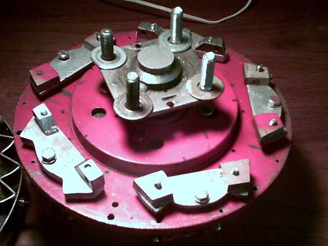 EH Motor Rotor with 5 Escapements
But owing
to the points on the escapements meshing with the teeth on the output
rotor, they have to oscillate
back and forth in order to spin.
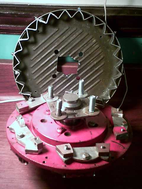 Output Rotor (behind) with 25 'Teeth'
'5 Star' version finished December 13th
At low speeds they move freely and easily, but as
speed increases they have exponentially more and more
resistance to being
oscillated. They are continually pushed in one direction or the other
as they spin, a bit like pendulums on steroids.
All five escapements now operate at the same time: they
move alike, in unison along the 25 rotor teeth. In the previous
version, six escapements around the rim all operated 60 degrees out of
phase with each other. The new way gives a single quintuple strength
torque pulse (the total 665 escapement grams) just 1/6 as often as the
previous six single strength
pulses (133 g each) - a longer period with correspondingly stronger
hits: the better to couple the peak
force to the tire and road with less averaging out of the torque.
Where one or
the other end point of the escapement hits the next fan tooth is where
their direction of swing,
the oscillation, suddenly
reverses. For most of the oscillation, nothing happens and the motor
spins freely, but at this point five hammers hit the nail. The average
torque of the output rotor is the same as the motor's torque, but it's
divided into the free swings with no torque, and the sudden "5 hammer"
torque "bumps", hopefully at least ten times stronger than that
'average'. It's a better approach to "gearing down" the motor than
gears, because
it's continuously variable depending on torques and speeds.
Ways to improve on this basic design now are:
(a) make it a larger diameter. This is much the best improvement,
giving all the forces more leverage. It also makes (c) or (d) (below)
more feasible.
(b) reduce the number of teeth. This reduces the number of hits
per revolution. Changing from 25 to 20 teeth (if practical, still with
5 escapements) would mean
20% stronger hits, 20% less frequent. (I'm pretty sure reducing to 15
would be impractical. Then again...)
(c) increase the number of escapements. (with the number of teeth
being a multiple of the number of them so they're in phase.) This
increases the mass of the hits.
(d) increase the mass of each escapement. Wear to the unit from
heavier hits needs to be considered.
As the car starts moving with the repeated strong 'hits',
the output rotor speed starts to catch up to the motor speed, and the
torque hits (and noise) strength and frequency are gradually reduced as
less torque is needed. One could add a spring to one or more of the
escapements so that below a certain torque, the converter would lock to
the motor speed.
The Test
The "5 star" version was completed on the night of
December 13th, and on the 14th it poured rain, so I worked on the new
A3938 motor controller. On the 15th I did the test with the wheel
jacked up that uncovered the
motor controller problem. After finding the problem, I took everything
apart in disgust. In retrospect, I should have tried to move the car on
level pavement while it was all together - it might have traveled and
made a good
video.
These tests, with carrying the heavy motor and batteries,
and jacking up the car wheel, are quite hard on my back, so I don't do
any more of them than I can help. Everything also takes time to set up
and dismantle, and the weather has to be good.
Next Unit
I see no need to make another unit for the next tests.
however, in making one prototype one sees its deficiencies and improves
the next unit. This is certainly no production design. Two things of
note are that (a) it's noisy and (b) bits
of aluminum dust are coming off it when the motor is spinning,
indicating it'll wear out rather quickly.
I think the noise level can be much reduced (a) by using
thicker metal and (b) by gluing on thick rubbery sound deadening strips
like car makers glue to body panels of cars - maybe a ring all the way
around the outside. Anyway, the muffler doubtless was invented after
the infernal combustion engine, not before.
The wear is of course less than on the first escapement
converter that only turned a few turns, and is improving. Probably a
good way to fix it is, instead of having the thickness of a piece of
aluminum hit the teeth of the ring, turn the escapement hook pieces
vertical and have the full inch height of the hooks hit the full inch
height of the teeth - or however tall they need to be to have low wear.
Motor Currents Torque Converter?
At the same time I was putting together the 5-star, I also
had been working on figuring out the performance of the EH motors. An
interesting equation was for the 'stalled', 'locked', or otherwise
stopped rotor if the full voltage of the batteries was applied
unmodulated: I = V / Rm. 36V/.064ohms=562.5 amps. Obviously this would
burn out the motor controller or the motor coils in short order. One
could
hear in my 2008 car move test that the motor was being driven beyond
normal
limits to get the car to move. It would have soon overheated. So, the
powerful field of the supermagnets couldn't be used directly to turn
the car wheel because making the electromagnets similarly strong to
push them with, would burn out the controller or the motor. I've said
it before: only a much oversized motor could supply the needed torque
directly at 1 to 1 RPM with the wheel.
But what if high power or even full power were applied
for, say, 1/20th of a second, twice a second, and then it was turned
off for the rest of the time, a 10% duty cycle? That would give
momentary pulses
of high torque just as the torque converter gives, without the
danger of overheating the coils with a too-high average current. The
mosfets are theoretically rated for 840 amps of momentary surge as
well, or 1680 amps together. They might just handle a burst of over 500
amps then as well.
In effect, the motor and controller could - possibly - act
as an electrical torque
converter. The strong field of the supermagnets could be matched for a
moment by the coils with high current, and the car would start moving
by pulses.
The questions to be answered before building the circuitry
for this and trying it out would be:
a) Roughly how much torque could the motor provide? That one seems easy
to
answer in theory: The torque constant worked out to .171 N-m/A.
Multiply by 500 amps: 85.5 N-m.
b) Roughly how much torque is
required to
turn a car wheel for decent performance -- an actual figure in
newton-meters or foot-pounds. The web is quite vague on this point.
After all, it all depends on the car, how steep a hill it is or how
fast you want to accelerate, etc. But it appears that at least a few
hundred would be required.
c) How much current can the
controller, and the motor, take, for brief blips of time, without
burning out immediately... or much too soon?
d) Are there negative factors, such as magnetic saturation of the coil
cores or simply insufficient force to be had in any case between the
supermagnets
and the "super" coils, that would reduce the force available to less
that the mathematical answer to question (a)?
e) Losses increase with the square of the current, and the current is
extreme. How significant would be the extra energy used to run the
motor in short, high current pulses instead of at "steady state"?
It would appear that the last three questions are
redundant
in light of the answers to the first two. One anticipates that it would
give the same sort of lazy
crawl across
the pavement that I got in 2008. Even if all else is in order, it's
likely that the very high currents and consequent very low motor
efficiencies will drain the battery needlessly quickly. But if the
mechanical
torque converter (now that I've finally made one that should work
well), should in fact be unnecessary, redundant, that would be worth
knowing!
The next day, it occurred to me that there was a simple,
if somewhat unnerving, way to test the idea: Put a motor on
the car wheel, put the car in neutral with the parking brake off
(chocks to limit travel), bring out 3 batteries, and "spark" two leads
at a time with the batteries. (gloves, safety glasses.) If one or
more combinations made the car lurch forward or backwards with some
energy, then the motor is physically capable
of making it work. If it just went "gzzzt" and didn't move, or moved
lethargically, it isn't. I recall doing something like this once trying
to measure actual torque, but the wheel was jacked up and all I did
then was break the hooks off my fish scale.
A complication for these tests is that the motor that's
set up for the car
wheel is also set up for the torque converter, not to connect directly
to the wheel. The other motors don't have the right mountings for the
car wheel. In view of the dim prospects this will work, or that it's a
good way to do it even if it does, I'll await some fortuitous
circumstance.
Turquoise Battery Project
Disassembling 9V Battery Discloses Interesting Construction
Techniques
I had disassembled one multi-cell battery previously and
found it simply contained a pile of individual button cells. On
you-tube, someone took apart a 6 volt lantern battery and showed it was
full of typical "AA" cells. However,
this Mn-Zn dry cell was different.
Around the outside was a sheet metal body. Inside that was
a single formed tube of shrink-wrap plastic, isolating the body from
the workings. Solid plastic end pieces did this job at the top and
bottom, the top piece also having the metal terminals, and a thin
insulated metal strip that ran down the side to connect the bottom cell
to "-".
Inside the shrink-wrap was a layer of wax to help seal the
cells inside. Breaking the wax separated the individual cells.
Each of the six cells was wrapped in its own little piece
of shrinkwrap, with some more wax inside. They consisted of: a thin
carbonized plastic sheet, so thin it was flexible, adhered to and
covering a zinc sheet (the "-" electrode), then a piece of
thick paper
that wrapped up a manganese/carbon electrode briquette (the "+") on
five
sides out of six, leaving the top open except for the shrunken wrap,
which covered much of it around the edges. But the middle was open with
the briquette contacting the carbonized sheet of the next cell above.
The bottom cell had no carbonized plastic sheet, and there
was a double sheet between the top electrode and the terminals at the
top to keep the electrode and electrolyte away from the "+" terminal's
metal.
This construction is somewhat along the "stack of cells"
lines I've been
moving towards to use for multi-cell batteries. Mine would be
much larger in area.
The MnO2 electrode briquettes were about 5-1/2 mm thick,
the first ones that seem to verify my ideas that 3-9 mm is a good
electrode thickness. Of course, these are low current cells, so for
high current batteries with similarly thick electrodes, the KCl had
better turn out to be a very good electrolyte!
The resistance of the carbonized plastic sheets seemed to
be around 12 ohms, but if the thin sheet was wrapped around the meter
leeds, this dropped as low as 2 or 3 ohms, verifying that most of the
resistance measured is due to the limited contact points between the
meter leeds and the carbon.
Later I wondered if similar carbon impregnated plastic
could form one or both faces of a cell, sealed with MEK in the usual
way to the ABS plastic sides like I've been using? With the faces held
closed by an outer shell, that could make a nice multi dry cell layout!
But I decided my sticky, pliable sheets (below) would be
easier when I finally found a way to get the aluminumfoil off after
baking them wrapped in foil.
Ni-MH Price Reductions - Car Battery Experiment?
Perhaps a year ago I wrote that the price of Ni-MH
batteries seemed to be being kept artificially high, 1000 $/KWH, which
was probably hefty royalties to Chevron/Cobasys and their 125 acquired
MH patents, imposed not to make money but to keep the prices of the
batteries from becoming economical for electric transport.
While many sources and sizes are still about that price, I
now see 3 or 4 sources on the web selling Ni-MH "D" cells of 9 to 12
amp-hours capacity for $6-7 in tens quantities, or 600-700 $/KWH. (In
fact, I also see NiMH "AA" cells for around 450 $/KWH - worth
considering, though 4x more soldering to make the same capacity pack -
and I don't see them with solder tabs for that sort of price.
Theoretically you shouldn't solder straight to battery terminals, but
by heating quickly, getting the wire on in a couple of seconds, and
getting the heat off at once, I've almost always had good results.) In
2003 people were talking about making Ni-MH's for 300 $/KWH, but for
larger batteries. Since then, metals have gone up considerably, and
these are small cells (the biggest available are "D" and "F"
('stretched D') thanks to the vested interests). $450 to $600 is at
least headed towards more economic levels.
On my car I measure about 200 amps as the starter motor
starts up with the voltage dipping as low as around 9 volts, and 155
amps during steady cranking. I previously thought that the Ni-MH "D"
size was probably only good for around 20 amps discharge rate, thus it
would take perhaps 6 or 8 parallel sets of ten in series to replace a
car battery, ie, $600 or more. But I see radio control groups on the
web talking about 50 amps from Ni-MH "D" cells. I think it should only
take about 3 sets; maybe 4 -- perhaps one more in freezing weather.
Most of the economical cells seem to be rated around 30 amps, but
starting the car doesn't normally take long and they'd surely put out
more for a few seconds. Voltage will be just a little bit higher than
with lead acid with 10 cells in series (or a bit lower with 9), but I
think car alternators should be able to handle it as-is. 30 of these
cells would be about the same effective capacity as a (new) 35
pound lead-acid battery and weigh about 8 pounds, lightening a car by
over 20 pounds.
Now with the lower prices and realizing fewer batteries
are required than I thought, I'm minded to try replacing my car battery
with 30 Ni-MH "D" cells for around 200 $US list price just as an
experiment. (or 120 "AA" cells for $175) They are likely to last longer
than lead acid even with the sodium sulfate added, and being lighter
would continually save just a bit of gas on every trip, so they would
probably pay for themselves. The only trouble is that the lower cost
battery sources are all in the USA - in fact, here in town I've never
even seen a Ni-MH "D" cell for sale. (That's disregarding "AA" cells in
placed in a "D" cell package. You can tell these imposters by their
light weight and the specs on the package.) Tacking on shipping, UPS
border charges and perhaps duty will add $75 to $100 to the price -
more than a new lead acid battery, locally available. Maybe I should
wait for the US$ to drop some more... but the value of doing the
experiment sooner is probably greater than a lower cost later.
With the lower prices and high currents also I could
conceivably use Ni-MH "D" cells for the electric car: As a minimum, 120
of them would give 36 volts at 120 amps (at 30 A max rate), and 40 AH
(1-1/2 KWH), for $800 (++). Then 10 AH increments for $200 each. It's
not cheap, but less than the $2000 Ni-MH starting price I'd calculated
previously. The 40 AH performance would be better than for 70 AH of
lead-acids and they're much lighter.
If anybody else (in Victoria BC) wants to get some Ni-MH
batteries at the same time, please call or e-mail me... we can get the
best quantity discount and lowest shipping charges per item with a
bigger order.
Carbon Sheets (meanwhile, back at the ranch...)
My attempts to make flexible, impervious graphite sheets
using tar or pitch and powdered graphite had been foundering on the
fact that they really should be wrapped in aluminum foil (or something)
to keep the air away as they were baked in the oven, but the aluminum
stuck quite solidly to the work and they couldn't be separated without
wrecking it.
On the 17th I tried again with a piece that had also had
hexadecane mixed in. The trouble was no different. But that same night
I was
(finally) replacing some leaking O-rings in my bathroom sink, and I
suddenly thought: it's more gooey when it's hot - it turns to liquid on
the stove... what if I run
cold water on it?
Sure enough, much of the aluminum peeled away easily, even
suddenly. If it hadn't already been somewhat shredded, it might have
come off nicely in one piece. Putting the sheet in the freezer for 10
minutes would probably work even better.
I also thought of another expedient both to decrease the
stickiness and improve the conductivity: paint the sheet with graphite
power before wrapping it and putting it in the oven. It should adhere,
especially to
the stickier areas that cause the most trouble.
I put the sheet of
tarry graphite into a battery box
I'd prepared a while back.
Compacted and oven heated sheet of carbon (tar, hexadecane, graphite)
as a conductive end layer behind terminal post in battery box.
I may re-compact the next sheet after baking it to smooth it out.
Behind the sheet and in contact with it is a terminal that
goes to the outside.
Presumably, the tarry sheet will seal against the side of
the box,
preventing any electrolyte from getting in (and air leakage), so a
terminal post of any
metal at the center underneath, in electrical contact with the sheet,
should
work fine. And a copper or other mesh on the outside side could up the
conductivity.
Building the battery from the "plus" terminal up, the next
layer on top of the impervious carbon sheet would be the dual-valence
nickel-manganese-graphite electrode briquette. With the tarriness of
the
carbon sheet, I expect good electrical contact would be made between it
and the briquette without any sort of grille or mesh.
This seems to me to be the most promising construction
idea yet since I finally realized that every common metal would
dissolve in
salt electrolyte. (Jungner really hit it lucky when he found pure
nickel
would withstand strong alkaline electrolyte!) But the resistance of
this particular sheet was too high and I pulled it out again - I didn't
add enough graphite when I mixed it.
Naturally, I couldn't put much time into the project while
working on motor evaluation and then design revisions.
A Battery Design Concept
I've expanded on the above and placed an overview of my
latest ideas for a
good battery design here: www.TurquoiseEnergy.com/batts.html
.
In this I envision using the conductive pliable carbon
layer
to seal separate cells in a multi-cell flat plate battery, eliminating
the shrinkwrap
plastic of the 9-volt cell mentioned above. The pieces would be
cut very carefully to seal against the edges of the case and prevent
electrolyte
from conducting between cells. A ring of wax could also be painted
around the edge to help ensure there were no leaks.
As I now conceive it, the battery in its simplest form
would simply be sheets or plates of various materials, stacked as
layers within a tube, that are pressed together as it grows.
Hopefully I'll be able to try out this design in January
or February.
http://www.TurquoiseEnergy.com
Victoria BC