Turquoise Energy Newsletter #36
Turquoise Energy Ltd. News #36
Victoria BC
Copyright 2010 Craig Carmichael - February 3rd 2011
http://www.TurquoiseEnergy.com
= http://www.ElectricHubcap.com

Contents/Highlights:

Feature: Ni-MH dry cell car battery packs are ideal car starter batteries: green, lightweight, very long life, economical!

Month In Brief
(summary)

Electric Hubcap System & Motor Building Workshops
  * Making iron-powder coils (much easier!) -- with nanocrystalline ceramic rutile skins.
  * EH Motor Coils: for sale - $10 each (triple magnet sensors, mounted, wired - $30 ea, 1" I.D. Bearings & Bearing hub - $45 ea, PP-Epoxy Stator - um...)
  * Next Motor, with the PP-epoxy stator and new IP coils.
  * 'Upside down' stator? - PP-epoxy plate between coils and magnet rotor offers superior protection. (or a ring covering all the coils.)
  * Super Electric Hubcaps: Super Torque and Low RPM for direct wheel drives.
    - 10 KW, 18", 4x torque, 1000 RPM
(use two under hood - connect to front wheels by CV drive shafts)
    - 15 KW, 26", 9x torque, 700 RPM
(use one - speed limited to ~80 Km/Hr)

Torque Converter Project (no test yet. It should work. Needed: a nice day, time, and a stronger back or lighter batteries! NiMH batteries are on order.)

NiMH Car Battery Project
- Get the lead out - of your car! Reduce vehicle weight! Reduce Fuel Consumption! Green batteries!
  * Found: dropping Ni-MH dry cell battery prices - under 450 $/KWH.
  * Experiments with Ni-MH AAAs & AAs showed very high currents are attainable.
  * Very long life (as proven by NiMH hybrid batteries) NiMH battery packs for starting cars: practical and now economical.
  * Replaces toxic lead-acid with 'green' NiMH; takes 15-25 pounds off vehicle weight.
  * improves mileage.
  * "4/3-AF" size is chosen for test battery pack.
  * Ni-MH car test battery cost: 152 $ (plus shipping, tax, ... $190.)
  * Pack is a bit small: 60 cells (23 AH,9C) starts car, but 80 (31 AH,7C, $250) would have been better.
  * Starts car and charges properly - ideally - with any car alternator system.
  * Recommended minimum amp-hours/amps rating: AH * 7 (7C) ≥ Starter Amps
  * Works Great! Are lead-acid car starter batteries now obsolete?
  * For Sale: 'D' cells are on order; ready made NiMH dry cell car batteries $320 (~210 amps, small car size) $420 (280 amps, medium car). Be in on the first batch - reserve yours now! 10% discount for prepayment.
  * Next item: battery tab spot welder for CNC machine production.
  * Footnote: NiMH dry cells for EVs idea; NiMH dry cells to make hybrids into plug-in hybrids idea.

Turquoise Battery Project

  * Conductive carbon sheet/layer mixes.
  * Next Test Battery is assembled: high resistances -- but they didn't rise over time.
  * Mn negatrode: bubbles, high self discharge.
  * Graphite surface cleaning/prep.
  * Next one: better currents; lowest internal resistance yet but still too high.


Newsletters Index/Highlights:
http://www.TurquoiseEnergy.com/TENewslettersIndex.html

Construction Manuals for making your own:

* Electric Hubcap Motor Building Manual
(latest rev. 2010/09/xx)
   - the only 5+ HP motor that can easily be made at home?
* Turquoise Motor Controller Building Manual
(latest rev. 2010/05/31)
   - for the Electric Hubcap. (Probably there are commercial controllers that would work, too.)
* 36 Volt Electric Fan-Heater (in TE News #22, 23, 25)
  - if you're running your car on electricity, you'll want a way to defog the windshield and keep warm. (This one I made - but you can buy them.)
* Lead-acid batteries:
Sodium Sulfate 4x longevity additive - "worn out" battery renewal. (http://www.TurquoiseEnergy.com/Na2SO4.html)
*
Nanocrystalline reflective rear electrodes to enhance DSSC Solar Cells.(in TE News #28, 29)
* Simple Spot Welder for battery tabs, connections (in TE News #30 - not the best welds, but article remains for ideas.)
* NiMH Dry Cells Pack Car Battery (TE News  #36 - economical, very long life, green, lightweight: replace your lead-acid battery!)

are all at:  http://www.TurquoiseEnergy.com/


January in Brief

   Here's a good news budget: A car battery made of NiMH dry cells was tested for perhaps the first time ever and shown to work without a hitch. As the Electric Hubcap work progresses, the motors keep getting better, alternate ways to electrify a vehicle emerge, and I'm now able to start offering for sale parts to help you make motors yourself. Progress is being made on developing new chemistry, high energy density batteries.

NiMH Car Battery

   An idea that nickel-metal hydride dry cells might be made into car batteries went from being a "theoretical possibility" to "wow, works great!" to "car batteries for sale" in a month. It works even better than I imagined. There were no complications: it runs everything, starts the car (theoretically good for almost 10 minutes of strong cranking), and the voltage of every car's alternator system (13.8v) fortuitously seems to be a nearly ideal constant charging voltage for it.


As far as I can find on the web - so far (hard to believe) -
this is the first NiMH car starter battery ever done.
small car 210 amp model (30 "D" cells) will be $320.

   Based on Ni-MH hybrid car batteries, one might suppose these will last the life of the car. Prices are dropping, but currently, initial cost of the cells alone is 3 times the price of a cheap lead-acid car battery, but the long life means eventual savings, and the lighter weight perpetually saves a bit of gas and boosts performance a little bit. I plan to outfit the CNC machine with a battery tab welder to make connecting cells easier.

EH Motors and Controllers

   With various jobs to be done, the motors and controllers continued eating up many hours during January. The motors were more refined at the end of the month than at the beginning. They were looking at 95% efficiency using the PP-epoxy stators and cheap commercially made iron powder coil cores -- with the paramagnetic coating idea from the ceramic cores project.

   These fine cores with the coating should economically achieve the objectives of the nanocrystalline ceramic coil cores project, so I'm definitely ending that project. The coating, and the nanocrystalline borosilicate glaze for DSSC solar cell reflective rear electrodes, are the project's productive outgrowths - one a part of the original plan, and the other a completely unexpected bonus.


The coils: Iron powder cores, epoxied wire, and an overcoat
(below) of nanocrystalline ceramic rutile (TiO2 mineral) in sodium silicate.


PP-epoxy stator with bearing hub and 9 coils -- Basically that's 1/2 the motor.
Upper left: the secret sauce, rutile (TiO2) - good dielectric... and Ti is paramagnetic.
(painted on one coil, but flaking off shiny smooth epoxy. Next technique worked better.)
Right: The coil winder.

   Easier to make coils permit me make and sell them, to make building EH motors easier for others. Even before finishing the test motor, I ordered 240 more cores (price break there), which arrived on the 27th, when I also finished and ran the motor. Coils are $10 each while my surplus magnet wire lasts. I can also sell the machined bearing hubs and the magnet sensors. The stators are currently considerable work to cast. Perhaps I can figure out better techniques. Everything else is pretty much "epoxy it on" (the magnets) or "bolt it on".

Super-size Electric Hubcap Motors

   I also started thinking about different versions of the Electric Hubcap motors, and decided two sizes would be especially useful: an 18 coil, 18" double size unit - 10 KW with four times the torque, and a 27 coil, 26" triple size - 15 KW with nine times the torque. Such big diameter, very low RPM motors should have plenty of power and torque to drive vehicle wheels directly - no gears, torque converter or anything. They would be too big to mount on the outside of a wheel, but could do great under hood electric conversions, connected straight to the front wheels by the vehicle's original CV shafts.
   They might be constructed something like bicycle wheels to reduce their weight, heavy plates being replaced by stiff spokes.


Iron powder cores 'viz':
Super Electric Hubcap sizes, 18" 10 KW double and 26" 15 KW triple, compared to CD.


   I didn't find time to test the torque converter - it's sat there all month, ready to go (with a couple of tweaks). You'd think I'd have made it top priority! but a lot was happening, and it is winter out there.

Turquoise Battery Project

   I did some more experimentation on my own battery designs. The more I do the more I realize that everything hinges on getting excellent connections across all the different layers -- and connections that aren't subject to corrosion in the battery's oxidizing, salt water environment. That means very well connected graphite and carbon parts, which of course can't be soldered or welded, and no metal of any common kind, at least in the positrode if not both electrodes.


A dirty froth from initial Mn self-discharge reactions.
It gradually bubbled for days when the cell was assembled and filled -
you can tell the energy is there!


    I made a couple of cells with a graphite sheet (cleaned with scotchbrite and hexadecane) behind each electrode, pushed against a carbon rod as the terminal post. Though resistance was high, it stayed constant, the first batteries I've made where the resistance didn't rise as metal connections corroded. For the second one I payed even more attention to cleaning the graphite sheets, getting good connections, and making flat surfaced electrodes with low internal resistances.
   With each attempt, I'm getting something with somewhat lower resistance, that behaves a bit more like a battery than the previous one. It's now under 3 ohms and can be charged and discharged - at poor voltages - headed for an amp-hour or more. But resistance should be at least 20 times lower.
   Further experiments to get good, low resistance connections are proceeding.


Electric Hubcap System & Motor Building Workshops

Toroidal iron-powder coil cores... with paramagnetic nanocrystalline skins

   The 9 sample cores arrived on the 7th from micrometals.com. They seemed fabulous. They were quite heavy and seemed pretty much as strongly attracted to the magnets as solid steel, so they're surely mostly iron. I decided to let the wire coil extend to just over one inch wide instead of the 7/8" I'd been using with the nail strips - I now know the magnet gap is large, and the coils are mounted off the stator on washers, so the wires won't hit anything. At this winding width, 15 turns of wire would fit in each layer instead of 12, and only four layers are required instead of five for 60 turns, shortening the wire a bit (hence lowering the low resistance bit more) and putting it, on the average, closer to the core for better coupling. As a side benefit, there'll be more space between coils, so the diameter of the motor can be shrunk just a bit (to 10" or 250mm) so the magnets don't stick out past the edge of the 6129 rotors to line up.

   The next day I got some plastic sheet that epoxy wouldn't stick to to make coil formers from, made them on the wood lathe, and prepared to wind some coils. I was going to paint some "sealtronics" high temperature rated epoxy resin onto the core and then onto each fresh layer of wire as I wound it, to make a nice solid core in which the wires wouldn't move.

   But then I thought back to my nanocrystalline ceramic cores project. One of the ideas in that project was to have a paramagnetic covering and or paramagnetic paste between the wires in the coils, to better couple the field generated in the copper to the main core material. So I decided to get out the sodium silicate "water glass", rutile, ilmenite, etc, powders, and do some coils with varying ideas on that theme. At worst, it would be no worse than the iron cores by themselves, but I'm pretty sure it'll be better.
   I thought sodium silicate would be as good a binder as the epoxy - unless it gets wet. The coils could be immersed in water and taken apart if desired, and the cores are plastic coated. (won't rust.) So, there'd no limit to the number of experiments that could be run, with relative ease.
   I understood that adding something like calcium or barium compounds will cause the mix to set permanently regardless of water.

   On the 9th and 10th I made a winding spool: a threaded axle, 2 side pieces and a center hub that the cores slid onto with a good friction fit. One of the side pieces was "sculpted" a bit to allow the 15 turns per layer to fit, a fraction over the core's 1" width. Later I realized the sculpted sides could eliminate the plastic center hub entirely - the core itself could take its place.
   I tried making a core, painting on sodium silicate to fuse the wires together. But it wasn't strong enough and it fell apart. So much for making one I could soak in water and revise later!
   On the 11th I redid it with "sealtronics" high temperature epoxy resin. The wires were unwound from previously wound but unfinished coils, and when I wound these coils, there was always some wire left over - sometimes over a meter, usually less. That reduction would lower the motor resistance a bit more. .061 ohms instead of .064 would be another 5% reduction in copper losses (and mass of copper). 20 turns of #11 wire (or perhaps #10) instead of 60 turns of #14 would be even more compact. (The three coils per phase would be wired in series instead of parallel.)
   I made two more late in the evening. (I kept the remaining epoxy in the freezer. 30g was enough for 3 coils.) The bottleneck is waiting over an hour for the epoxy to set (in a warm oven) while the coil is still in the winder bobbin to keep it from unraveling. I'll make another bobbin to two, or even have five or all nine, to permit doing more coils at once.

   Somewhere in the month I ordered 240 more cores (there was a considerable price break there) and thickened the second PP-epoxy stator to about 1/2", having noted the 3/8" one was bending towards the magnets owing to attraction of the coil cores to them, and it had become bowed like a shallow dish. It required a couple of wooden ribs to stiffen it.
   It wasn't until the 25th I finally got around to putting the coils on the second stator. Only one coil had yet been painted with rutile, and that was flaking off. They'll need a bit of scotchbrite or sanding to roughen the slick epoxy, or some sort of undercoat.

   On the 25th also, by chance my biochemist brother was in town from Toronto. He had said something about making the sodium silicate ("water glass") insoluble using calcium, and I asked him what form that calcium should take. Calcium carbonate? No, that was already 'rock' and wouldn't react. Calcium hydroxide (lime)? Well, that should work... but how about calcium chloride? Then it would be a simple replacement reaction, leaving calcium silicate (insoluble) and sodium chloride (table salt), and involve no caustic lime.
   That sounded simple - calcium chloride is what they put on roads to melt ice, and I remember Capital Iron had a big barrel of it a year ago. I bought some. All that's left for me now is to try out ways of working with it. Should it be like a resin where one mixes the two parts and applies them before they set? or should I paint the core and then brush on the CaCl2?

   Later I realized the TiO2 might well achieve similar effect, and decided it would need further testing once I had some more coated. Attempting to make some more the same way as the first, however, gave the same results: hard, flakey coatings.

Upside-down Stator?

   On the 25th, considering the "super Electric Hubcaps", I had the idea that since there was a 1/2+" magnet gap, and since the PP-epoxy stator was electromagnetically inert, I could put the stator plate between the coils and the magnet rotor. This would change nothing electrically, but it would be a great way to protect the coils from the spinning magnets! even if something came loose, it couldn't get pulled towards the magnets and jam between the stator and rotor.
   Furthermore, if the stator was, eg, 3/8" thick, the magnets could never get closer than that to the coils, avoiding potentially finger crushing force.
   If not the whole stator, perhaps a ring of PP-epoxy could be placed over the coils. (I wanted to make a nylon ring instead of the nylon clamps, but nylon costs too much to cut a ring out of a big piece and throw out 2/3 of it as scraps.)
   It would be a great inherent reliability and safety increase.

   It feels like with all these improvements I'll never get to a final motor design! They all run, but each motor is better than the last. Excellent progress though, which is the road to attaining something approaching relative perfection!

Hall Sensor placement - spurious switching

   I noticed at times that the signals from the hall sensors would switch when between two like magnets - a source of dead spots and reduced power. With the oscilloscope on the signals, I discovered that, contrary to intuition, the signals switched properly and turned into the desired 'clean' square waves when the sensors were at least 1/4 inch below the magnets and preferably 3/8", rather than almost touching them. It must be that the metal rotor causes a bit of bending of the lines of flux that brings the opposite polarity down a little below the centerlines of the magnets. One more little thing to note and add to the motor building manual!
   Another idea is to put the sensors next to the edge of the steel rotor, just above the magnets. But with an upside down stator or PP-epoxy ring covering the coils, the sensors will probably end up on the protected side with the coils.

Motor Controller: balancing parallel mosfets

On January 6th, Tristan and I repaired a lab power supply I had been given, thinking it would help with testing the motor controllers. I noticed the emitters of the four paralleled pass transistors were balanced by .15 ohm resistors. The next day I found that the motor controller from the car was drawing current erratically, and discovered it had a blown mosfet - in one of two pairs in parallel for each phase. (The other pair must have had a bad connection, because the phase wasn't going 'high' at all.) Then I considered that I had done nothing to try to balance the load of the paired mosfets - merely tied them to the same wire. If one had a slightly lower internal 'on' resistance than the other, it would take more of the load instead of about half. And it seems the internal resistance goes down as the temperature goes up, so the one taking more of the load gets hotter and takes even more of it, creating a thermal runaway effect. Balancing resistors seemed out of the question - .1 ohms times 45 amps is 4.5 volts of loss and many watts heating up the resistors.
   But balancing 'resistors' could take the form of the tiny load sense 'resistor' - just lengths of copper wire. The mosfets were only 2 or 3 milliohms. All I needed to do was to connect them to the motor power terminal block via identical lengths of thinner wire from the two sets of mosfets to add a milliohm or two, equal in both sets, to balance out the load. Half the current would go through each of the two wires - two #14s is the equivalent of a #11. (It seems to me I've seen this sort of two parallel wires arrangement before, and thought to myself, "that's silly - they could have just run one heavier wire!")
   This was my earliest controller with the great double-row of mosfets arrangement, and it was getting pretty messy with various repairs and alterations, and fuses to every hi-low pair of mosfets. (The one to the bad pair was blown, which was why nothing more happened.) I decided to rip up the wiring and resolder everything in the latest arrangement to clean it up... and to balance the mosfets with double wires.

Regenerative Braking?

   People have asked about regen braking. Regen braking can evidently "add 20-30% extra range" in city driving. But the EH/torque converter system going direct to the wheel(s) should add about 50% extra range in all driving without regenerative braking.
   I finally realized that regenerative braking is done with motors with electric field coils instead of permanent magnet motors. These motors are less efficient than permanent magnet motors to start with, so it might perhaps be appropriate to note that they lose maybe 10%(?) more everywhere, then in city driving they are only making up for that loss (and hopefully more) with the regen braking.

   With a permanent magnet motor, the generated voltage varies only with speed - it can't be increased by upping the current to the field coils since there aren't any. That voltage is always less than the battery voltage unless speed is increased above 'max' by going down a steep hill at 'above top' speed. That doesn't mean there's no way to do regen braking, but it does complicate it. It should be noted that with the 50% added efficiency of the drive itself, even more (50% more?) would be gained from any regenerative braking that is employed.

   One possible way would be to have three transformers on the motor coils to up the voltage above the battery voltage. There would need to be different taps switched in for braking, eg by solid state relays, to keep the voltage at the right levels at varying speeds. (All switched off except when braking.)
   Another would be to change the three coils of each phase from parallel to series during braking, tripling the generated voltage. The switching would be very complex, and it relies on coils being wired in parallel to start with.
   Or, the generated voltage might be rectified with six diodes, and applied to charge some of the batteries, eg, 12, 18 or 24 volts worth at a time, sequencing through the batteries with each braking. Again, the switching would be complex. Or it could just charge the 12 volt battery that runs the car lights, etc. But that does nothing for range.

   But the most practical technique would probably be to simply rectify the voltages from the coils and then have some adroit DC-DC converter that can handle very high currents and varying input voltages (from say 8 or 12 volts to 45) and output current to the batteries (at say 42 volts, or depending on a brake pedal potentiometer) when the brakes are on. This would be a whole new unit virtually separate from the motor controller. If such a beast isn't available (which it may possibly already be) someone should make one - it's worth doing. It could work for most any EV motor.

   For the foreseeable future, I'll be working on the 95% efficient EH motors and the efficient torque converter to save 33% during all driving, the new chemistry batteries to extend drivable range with less weight, and perhaps means to generate the 2/3 remaining power needed. (More efficient DSSC solar cells on the car roof... ooh, ah!) The regen braking I'll have to leave for someone else or for some future project. ...Unless, of course, I have some clever inspiration for a really simple way to do it, or run across the perfect (and affordable) DC-DC converter off the shelf.

Super Electric Hubcap Motors for Direct Drive of Vehicle Wheels

   My original plan was that the Electric Hubcap motor should drive the car by directly turning a car wheel. When I made and tried a motor, I found that it would barely push my car on level pavement. I estimated it would have taken about 7 times the torque to be practical. The car only had four wheels to put motors on, so I started the torque converter project. A bigger motor wouldn't have fit my 13" car wheels, and going too much larger would anyway be too heavy to put on a wheel.

   But it has often been in my mind that one could theoretically make larger versions of the Electric Hubcap motors -- probably just using more of the same coils, and more of the same magnets, to avoid complication. The regular 5 KW motor is 10" diameter with a 4" torque radius, 9 coils and 6 magnet poles, runs 0-2000 RPM, and weighs 25 pounds.
   Using PP-epoxy stators plus steel centers, larger size trailer axle components and magnet rotor disks cut from 3/8" steel plate, larger motors should prove practical. And the larger the motor, the lower its speed, making it more suitable to match car wheel RPMs directly. 95% motor efficiency and no-loss direct drive would extract at least 50% more range from whatever batteries are used than typical EV drive systems. Two specific "super" sizes come to mind.

   The first size is 18" diameter, 10 KW with 18 coils and 12 magnet poles: double the original coils and magnets, and also double the effective torque radius - 8". With twice as many coils and motive force at twice the radius, it would have four times the torque, and it would be about 0-1000 RPM, an ideal range for directly driving a car wheel with no gearing. With four times the torque, one motor would certainly roll a vehicle on level ground. With two, one on each side, they would have eight times the torque of the original motor and should push a vehicle up hills. That could make it practical.
   This size of motor might just fit on larger wheels, but it would be intended for smaller, lighter vehicles that tend to have smaller wheels. It might clear the ground on smaller wheels, but a flat tire would certainly plant the bottom of the motor on the ground. Some sort of emergency fold-up motor mounting would be necessary - a nasty complication - or some sort of "flat-proof" tires would be necessary. Then, these motors might weigh around 60-70 pounds if made with solid plates, and the suspension details would become quite important.
   Another use for these motors would be for electric conversions rather than add-ons. For this, put them under the hood, attached at an angle to the vehicle's original shafts with CV joints to the wheels, one to each wheel.


Viz: 18" rotor diameter with 18 coil cores & CD

   The second major size - very super - would be 26" diameter, 15 KW with 27 coils and 18 magnet poles. This is triple the original's force and the torque leverage is at 12" radius instead of 4", totaling nine times the torque. The theoretical top speed (based on the original motor and parameters) would be 667 RPM, which would limit the top vehicle speed to a value dependent on the tire diameter: 67 Km/H for 13" wheels P155R13, and higher with increasing diameter. Doubtless the RPM could be pushed up somewhat, and with larger wheels, 80+ Km/Hr could be had.
   This one motor would probably have the torque to run a car with direct drive to one wheel, but it wouldn't fit on any wheel. It would have to go under the hood as described above. Two 26" motors driving both front wheels would have oodles of oomf. With solid plates, this motor would doubtless weigh over 100 pounds.


Viz: 26" rotor diameter with 27 coil cores and CD.

   In order to reduce the weight of these larger motors, they might be made something like bicycle or motorcycle wheels with a center hub, light spokes, and the motor parts on the rim. A 26" O.D. rim of 3/8" steel, 2" wide for mounting magnets on (24" I.D.), weighs only 15% as much as a 26" O.D. solid plate. and costs a lot less, too. A 28" PP-epoxy stator would need to be quite thick to take the stress, and even a substantial solid metal center part would again be heavy.
   However they're made, I know I'll be wanting that unfinished pulsejet steel plate cutter working!

   My current idea of motor controllers would be wire the coils in two (for 18") or three (for 26") separate sets of nine, and to feed the same control and magnet sensor inputs to two or three of the same motor controllers I'm using now. This would avoid designing new larger controllers with their additional complications. Two or three controllers could be fit into one double- or triple-gang chassis.


Mechanical Torque Converter (MTC) Project

Hampered tests: blown transistor in controller

   I wrote last month that the converter tests had been hampered by a weakness of the motor controller, which I attributed to the MC33033's operation. This month I found a blown mosfet and an intermittent bad connection - one phase was pulling low, but usually not high. Occasionally I noticed a dead spot where the motor wouldn't start turning, but I attributed it to bad signals from the hall sensors, which was also happening. (Now I've found a fix for that.) I have no idea how long it's been blown. This would have limited the motor to 2/3 power.
   An intermittent connection would explain why the converter occasionally suddenly seemed to have much more torque than at other times and on those occasions I could scarcely hold the jacked-up wheel back, if at all. I'm pretty sure that when the controller was working properly, even with too much current limiting, the car would have moved -- and even before the latest and doubtless best '5 clock escapements' converter layout.

   There's a lot of work to be done with the new controller and all the motor improvements, though I'm theoretically ready to run another test. Currently I'm just figuring out improved design ideas for the next "5 star" converter in my head - one that will last thousands of kilometers rather than the prototype's few - until I have time to put it together.


Ni-MH Dry Cell Car Battery Project


Long-life NiMh Battery under the hood - 20 pounds lighter.

   On looking up Ni-MH batteries on the web, I found that small NiMH dry cells seemed to have both dropped in price and improved in current capacity in the last year or two. It seemed to me that it might now be practical to replace lead-acid car batteries with a battery of NiMH dry cells.
   In fact, I'm not sure the currents have gone up -- it's just that some of the web sites are actually giving the current specs now, and I hadn't known previously that they were rated that high. I also experimented with some heavy load tests of my own on the 5th and 6th with AAA and AA cells that I already had. Results from these experiments looked very promising, and are at the bottom of this article.

   I could find no indication on the web that anyone had tried replacing 'regular' lead-acid car batteries with Ni-MHs before. Even in hybrids the 12 volt battery is, oddly, lead-acid. It seems hard to believe no one has, but in the general spirit of battery experimentation I decided I would do it as a short side project.
   (The high currents also eliminate the only remaining reason I know of for selecting Ni-Cd cells: their supposedly great current capacity. Ni-MH now has it! I think Ni-Cd is now a dead chemistry with no real purpose to its existence. IMHO, the worst features of NiCd are low energy density by weight and a tendency of the dry cells to short out long before their supposed lifespan, resulting from the tendency of cadmium to grow rather dendritic crystals on charging and discharging. Toxicity I think is secondary: cadmium is a toxic heavy metal, but so is lead, and that doesn't stop anyone from making and using lead-acid batteries.)

   The progress seems to be largely due to Chinese efforts and the batteries are mostly imported from there. Here in the west, science, industry and government have let us down. The cutting edge of battery technology and its commercialization have moved elsewhere, and this is not wholly due to low labour costs in Asia. In the USA, an important company is talking about being able to manufacture large NiMHs for just 200 $/KWH, the lowest price I've seen yet, in spite of the price increases of metals (and just twice the price of lead-acid (if that), as I was saying they ought to be) -- but in spite of these glowing forecasts, they aren't actually making any.
   Talk is cheap, and I think the talk and the corporation shuffling activity may well be just a blind to lull the public and government into thinking something is going to happen soon, to forestall complaints and possible legislation demanding actual battery production. Chevron-Texaco has plenty of (our) money to produce these batteries - NOW! - if they wanted to.


Advantages of using a NiMH dry cell battery pack for a car battery:

* 40% of the weight of Pb-Pb/H2SO4 - saves gas.
* Should outlast Pb by at least 3 to 1 if not 4 or 6 or 8 to 1. This means they are cheaper. Ni-MH is a proven long-life technology that has been used in hybrid cars and electric cars with excellent results.
* Pb's life is seriously shortened unless kept fully charged, and severely shortened by even one overly-deep discharge. NiMH can be left at any state of charge and recharged 'whenever'. It isn't damaged if not kept fully charged, though it sustains capacity reduction if virtually 100% totally discharged.
* Safer - no big reservoir of acid to spill or splash.
* Non-hazardous to the environment. When they eventually do wear out (after 1 - 3 decades of service?), they can (if desired) be thrown in the trash like any disposable dry cells. (Of course, recycled battery metals can make manufacturing costs low, like they do now for lead-acid.)


Typical 30 pound Toyota lead-acid battery with the 10 pound NiMH battery in front of it.


Disadvantages:

* higher initial cost. No one is mass producing them yet. But doubtless the price of the cells will continue to come down.
* Availability. So far as I know so far, I've made the only one. I will supply small car size batteries for $325, or $425 for 280 amp starter size. 10% off for pre-payment. I can measure your car's starter current.
* Make your own: the cells are available to those who want to take a few hours to put their own battery together, but of course it's work.

Configuration

   Meanwhile back at the ranch... 'Sets' or 'banks' of ten batteries in series would provide 12 volts. Then enough sets would be required in parallel to get sufficient current to turn the starter. I was concerned about charging in the car: there might be minor problems with ten cells being slightly over typical lead-acid voltages, or nine being a little under, but even if they occurred, there were probably workarounds. It turned out there were no charging problems at all, with ten cells per 'bank'.
   It gradually dawned on me that storage capacity was a minor issue: with the high currents of starter motors, the key battery spec was amps per dollar. Any batteries that would provide the current would also provide sufficient amp-hours.

   One selection caveat that should be mentioned in passing is that the cells are only good down to -10ºC. That's okay in Victoria BC, but if you live in Edmonton or wherever, you need to select from newer cells good down to -30, or perhaps get a battery blanket/heater that comes on with your block heater and is warmed by the engine.

   In passing, note that 10 amp-hours of Ni-MH is worth at least 15 amp-hours in a new lead-acid (if not 20) owing to the way they're rated and the discharge characteristics, plus the fact that Pb-Pb shouldn't be discharged by more than 60% -- and should then be very soon recharged -- whereas NiMH goes to 90% discharge -- at good voltage throughout -- and doesn't care when it's recharged. And lead-acid amp-hours are rated at a 20 hour discharge rate (C/20) whereas NiMH are usually rated at C/5. If the lead-acid is discharged at C/5, it has a somewhat reduced amp-hour rating from the label. It gets worse for faster rates, especially greater than C/2, whereas NiMH's ratings are much less affected by rapid discharging even over 1C or 2C. Many are rated for 3C continuous discharge, eg 30 amps for 10 AH D cells.

Starter Motor Currents

   So... how many amps? I found my Toyota Turtle starter seemed to draw 200 amps for less than a second as the key was turned, and 150 once it was cranking. That was in weather around the freezing mark. I got readings only up to 180/115 amps on a Toyota Fourcrawler, 220/120 on a recent model Toyota sun border, and 225/180 on a Mazda Meow, in 5 to 10ºC weather. A Ford Horse showed 275 amps. Unfortunately all these other vehicles kept starting and I couldn't get a steady reading, so these are rough approximations. (Do I have the only car left without fuel injection?) A big car might take up to 400 amps, and the worst big diesel pick-up trucks in cold weather 750 (these usually have two hefty lead-acids).

Choice of Cells

   To replace lead-acid car batteries in small cars would require cells that would deliver those currents for the short periods needed to start an engine. I would aim at 200 amps, or near to it, for my own car. (I should carry the current clamp and meter around with me, and measure more cars if opportunity provides.)
   Measuring some AAA and AA cells indicated they would put out far more than their rated current, and it was these measurements that convinced me the idea was practical. My electric drill NiCd pack battery cells would put out 20 amps from something like a "2/3A" size. I was pretty sure it would work. Since the duration is very short, the main concern was whether the bursts of current would shorten the excellent NiMH "1000 cycles" battery life.
   But then I found cells that were actually rated for those sorts of high currents, making it feasible to make up a pack that actually had a 200 amps rating, or something close to that, to ensure the batteries were being used within their ratings, or not far outside of them.

   Of interest then were lower cost, high rate cells. (Note that "C" is the rate in terms of the amp-hours, ie, at "1C" a 10 amp-hour battery delivers (or charges at) 10 amps for one hour. At ".1C" or C/10, it delivers 1 amp for 10 hours, and at "5C", it delivers 50 amps for .2 hours (12 minutes).)

* "Titanium" 12 AH, 5C D cells  (60 amps, ~450 $/KWH, 11 ¢/amp),
* "Tenergy" 2 AH, 10C AA cells (20 amps, ~670 $/KWH, 8 ¢/amp)
* "Tenergy" 3.8 AH 9C-12C "4/3 AF" size cells (34-46 amps, ~560 $/KWH, 7 ¢/amp).

   Unfortunately there were no "10C" D cells. If there were, a pack could be made from just 20 of them. As it is, it would need at least 30 cells - 40 to be technically within ratings.

   There were cheaper AA cells down to about 410 $/KWH, but it would take many sets of them to start a car - a lot of soldering or welding.

   60 Tenergy "4/3 AF" cells, 3.8 AH "high rate, 9C to 12C" seemed to provide the most bang for the buck, so I ordered them. The chief problem with the AAs was that I'd need to solder 100 or more of them. The chief problem with the "Titanium" Ds (of which only 30 would be needed to supply a rated 180 amps) was that the store was out of stock. The 4/3-AFs came from all-battery.com , which turns out to be Tenergy's retail outlet, in sets of 30 for $76. Two packs for $152 gave six sets of ten. 3.8 AH x 9C x 6 sets = 205 amps, or x 12C = 274 amps. I thought that given that the 200 amps is for less than a second and that 9C is the minimum rating, five sets would be just fine. At 9C: 171 to 228 amps. That would bring the price down to 125$ - just double the price of a lead-acid, and it would surely last much longer than twice as long. It would also reduce the soldering some. Five sets would be 19 amp-hours; six sets, 22.8. (It turned out that 5 sets barely started the car, the starter cranking at only 7.1 volts with fully charged batteries. In use, six sets proved to be a bare minimum - because the "9C to 12C" spec on the web site was an error. They were ordinary rate cells.)


NiMH Batteries - Size 4/3AF.
(Gosh,
NiMH really is green!)

   Tenergy also said they had "high rate D cells" not shown on their sites, but that a large minimum order (3000) would be required. Further inquiry as to specs and price showed they were 9 amp-hours, good for 45 amps continuous, at around $5 each for 3000.  They didn't give me a higher figure for momentary current. They might - or might not - be better than the regular D cells (30 amps continuous, 50 amps short duration) in this application. Seems to me 30 would be required either way. Only with F cells might one make a pack with only 20 cells. More are probably required for larger cars regardless.

The Battery
   Meanwhile, back at the ranch... On the 18th the cells arrived. They were bigger than I expected and pretty 'industrial' looking. Good! They wouldn't fit in the charger, being a little longer than D size, though much thinner. I spent most of the afternoon soldering together the six sets of 10 in series. For this I flattened #10 solid wire, tinned it, and cut it into ~20mm lengths. I soldered these copper "bars" to connect each set of 10 cells into a 12 volt battery. I spent most of the evening soldering loops of #12 solid wire to the ends of the leeds as lugs to fit on a bolt that the car's battery terminals could attach to. I hammered these loops flat so that 6 wouldn't occupy an excessive length of bolt shaft. It developed that the bolts would have to be about 2.5" long, and I ended up cutting a 6" piece of 3/8" diameter threaded rod in half.


The soldered battery. Parallel cross wires are
to help balance cells and support any weaker ones


   All literature says not to solder directly to batteries, but I've never had any trouble doing it. (Another tech says the same.) I heat quickly and I don't keep the heat on the terminal long. Best guess: it's possible enough heat could burst the cell and (worst case) blind the solderer with the caustic alkali inside. The battery companies don't want the potential liability, so they just say "Don't solder to them." rather than give careful instructions, provisos and warnings. Perhaps I'll wear safety glasses next time, just in case. Or, heat for too long could simply wreck something inside - hasn't happened to me yet AFAIK. "Don't solder" creates a whole extra service of welding tabs onto batteries for soldering to. Welding is much hotter, but the heat is on for such a minute(?) time (bad pun in here somewhere) that it doesn't spread far. Welding is also faster if you have the equipment, but many of the welds from the cheap discharge welder I made really aren't very good and I went back to soldering.
   As I finished each set, I attached it to the "new" 30 V, 10 A lab power supply set to 14.2 volts, to charge at an amp or two. (New = made 1993, sat in pieces dead in a garage for ages, pieces  were given to me, sat around here 2 years, 4 faults repaired earlier this month - good as new! (Thanks to Billy for taking good notes and keeping the pieces together and to Circuit Test for sending the schematic!) Now I have a real electronics lab, eh?) They were altogether drawing up to the six amps I limited the current to, and by mid evening all six sets, each 3.8 amp-hours, were fully charged and drawing little current.

   The next day, I tried them on the car, first just one set, then adding a set each time. Even one set ran the lights (11 amps) and horn, though only at 11 volts, but it took five of the six to turn the starter and start the car. With all six the starter sounded healthy enough, but seven or eight sets wouldn't have been amiss. As exciting as actually starting the car with a bunch of dry cells, was seeing the car's charging system charge them just about perfectly, an initial 16 amps gradually dropping away as the batteries attained a good charge. All the voltages were a little higher than for the lead-acid (no load: 13.6 V; headlights on: 12 amps, 12.6 V; lowest starter voltage I read: 8.7 [versus the Pb's 8.2]) -- except the charging voltage, which was almost identical.
   Car charging systems put out 13.8 volts, and that seemed just right to have the charge taper off to nothing without overcharging the cells. My biggest concern of the entire project was they wouldn't charge well enough and some workaround would be needed. But at first they drew considerable current, obviously making good what they had put out to start the car.


Pentagon Headlight Panel with NiMH battery sitting on top powering 480 watts of lights. (40 amps)
Voltage was 11.6 volts. 100 AH RV/marine Pb: 11.8 volts. Small Car Starter Pb: 11.0 volts.
IIRC the room lights were on, but the pentagon (powered by the battery)
was much brighter and the rest of the room was underexposed.

   I spent more time that day and the next morning making a clear plexiglass case for them and properly wiring them in. (Of course, any cheap plastic container to keep it dry would do fine - I wanted to show them.) On the morning of the 20th, it was ready to go and Tristan came with a microcontroller with an A to D converter he'd put together on a breadboard, to chart moment to moment currents and voltages with about 17 readings per second. It connected to his laptop and a graph making program. We set a little table out by the car for the equipment, unplugged the sparkplugs, and obtained the following battery/starter performance graphs:


Lead-Acid: Starter cranking current

Lead-Acid: Starter cranking voltages. Decaying voltage with a few seconds of cranking
(after a few previous short crankings that seemed fine) betrayed emerging battery problems. You could hear it slowing down. It would appear the voltage should have stayed around 10 volts while cranking.

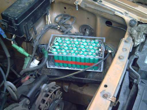
NiMH: Starter cranking currents


NiMH: Starter cranking voltages.
Seemed a little lower than with the meter the previous day,
but it's probably typical.

(The 1/2 volt reading was probably a bad reading -
the setup was prone to noise - or else a bad connection.)

   Afterwards, I removed the lead-acid battery and installed the NiMH one. I kept the lead-acid battery and wrenches in the back of the car for a while in case of any problem, but have had none so far.
   DIY note: Do up the "+" lead first with "-" unconnected, in case your wrench connects the "+" to the car body. That could make a very nasty spark - the kind that might melt the end off a wrench or put a new hole in the car body! I put the terminals on opposite ends so a wrench couldn't connect between them.


NiMh Battery: A mostly open space formerly occupied by a big,
heavy battery that barely fit under the hood.
(I soon made a "n" bracket to clamp it down. --
the original "L" bracket battery clamp attaches to the front of the tray
and the bolt seen at top center - grossly too large.)

   Previously unknown to me (well, I was just starting to suspect), my lead-acid battery was getting weak and wouldn't have cranked very long if the engine didn't quickly start, so this was not only a great experiment but a timely replacement. (I will renew the Pb, though!) The NiMHs would (theoretically) crank it over for almost ten minutes if necessary, and be none the worse for wear afterwards. They're also likely to last for ten or twenty years, maybe longer. Obviously I can't test the longevity of the NiMH battery in two days -- about the period of time from receiving the cells to final installation -- but they are already a proven long life technology as hybrid and EV car batteries. And for starting cars, it's very difficult to estimate the 'number of charge-discharge cycles' when they are only slightly charged and discharged, but many times per year.

   A hidden NiMH economy besides its lighter weight is that it becomes feasible to set the car's idle very low to save gas, down to where the battery isn't charging when stopped at traffic lights or in lineups. I was doing this anyway and it's doubtless why the latest lead-acid was dying sooner than expected. My fuel records indicate the lower idle saves about 10% on gas in city driving, though it might be said the idle was set on the high side before the adjustment, and that my driving style increases the percentage saving more than might be typical.
   It might also be said that the fuel cost savings from turning down the car's idle are much greater than the expense of replacing the battery after ten years (or even 5) instead of after 25 years. Plus, there's less oil being consumed and less pollution entering the atmosphere.

   There it is: one of my shortest projects, but very valuable and successful. Now starts the long term testing. Unless there's some very unexpected problem, lead-acid car starter batteries are really now obsolete. NiMH dry cells are a winner!

   I was somewhat surprised by the low cranking voltages from batteries with such high current ratings. On the 21st, having inquired about some quantity pricing and the cell specs, I was told the 4/3AF cells weren't "9C-12C" -- the info on the web site was in error. They were good for only about "6 to 8 amps", not 34! So I accidently made the battery pack in accord with my original idea: that NiMH batteries would put out far more current than their stated rating, but at a reduced voltage. However, the cranking voltage is at the low end and it sounds like a weak battery - even though it should continue to crank for many minutes if necessary. Had I known the true specs, I'd have estimated getting only about 25 max amps each (7C) out of them and assumed they'd need at least 8 parallel banks -- just the number I decided would have been nicer than six after trying them. (Actually, I wouldn't have chosen these particular cells at all. But they work!) The next week I discovered that the car won't start if the lights are on - a very good reason to have more than such a bare minimum!

Recommended Minimum Amp-Hours/Amps Ratings (there is no maximum!)

   I'm glad the cranking voltages are high enough that it works with just the six sets of ten - putting out 33 amps each, "9C", since that's all I bought. They are certainly the minimum amount you'd want on a car. Since they are just 'ordinary rate' cells, and since their performance appears proportional to the AAA and AA cells tested earlier, it looks like performance with any 'ordinary rate' cells would be pretty much proportional to amp-hours. 6 * 3.8 AH = 22.8 AH. I recommend 30 AH up for a 200 amp starter motor current.
   Three sets of regular 10 AH D cells (each rated at 30 amps continuous or 50 amps max), my original estimate of an appropriate set, would doubtless have worked better, and would start a somewhat 'hungrier' car, eg the small cars I measured as drawing around 220 amps. (and with half the soldering! but an extra $45 or so.) For the Mustang (275 amps) 40 AH would be a fair minimum. The "7C" rating is another way to estimate, and is based on my AAA and AA dry cells tests. 30 AH * 7 = 210 amps. 40 AH * 7 = 280 amps. Six banks (420 A) would do the largest cars, vans and PU trucks.
    All bets are off if you get special high-rate cells, eg, 10C. Obviously you can expect 10C out of them with good voltage, but it might be unwise to assume 20C would be available at a decent cranking voltage just because low rate cells can be used at double, triple or quadruple their stated ratings.

Charging

   Other than starting the car, the big concern was charging. Would the cells fail to charge, or else overcharge and develop problems? Would work-arounds or some converter be needed to get the charging into range?
   Theoretically, NiOOH is +.48 or +.51 volts (depending where you read), and hydrogen (that goes into the negatrode alloy to make it a "hydride") is -.833 volts, so the open circuit battery voltage is 1.34 or 1.31. But like lead-acid and other chemistries, it actually charges up to a slightly higher voltage when fully charged.
   The typical NiMH battery will sit at up to about 1.40 volts for an hour or two after charging, dropping to 1.37 volts a few hours or a day after charging it. Partly discharged or after a week or two idle, they may sit at, eg, 1.31 to 1.33. I initially charged the 10 cell sets using a constant 14.2 volts. At this voltage, some of the banks stopped drawing current, and some continued to draw a small amount. (They might have stopped entirely in another hour or two. or not.)
   Car alternators put out a standard 13.8 volts. Obviously, a battery that will only gradually drop to 13.7 won't draw a noticeable amount of current if fed with 13.8 volts. The cells won't overcharge.
   But would they charge enough? If they don't charge up, or charge too gradually, they might sit mostly discharged and have little or no 'oomf' when needed. Testing them in the car proved this doesn't happen. After running the 10 to 50 amps headlight panel for a while in the evening, and then testing them in the car for a while, they were sitting at 13.1 volts when I finally went to start the engine. They drew at first 16 amps from the car's charging system, which gradually got lower. On the next try, after delivering the 200/150 amps for a couple of seconds to start the car, the battery charged at 10 amps, which dropped to 6 within 30 seconds and 4 in a couple of minutes. Later car starting measurements showed this was typical. They were charging rapidly to make up what they had put out. It measures about 13.67 to 13.69 volts any time, even a couple of days after it last drive. This is as high as any cells charged and overcharged on the regular charger (higher than some) after a couple of days, so they're pretty fully charged. It's possible they are only charging 95% or (less likely) 90% -- but they're essentially charged. A charging voltage of 13.5 volts would be a bit too low and 13.7 "barely", but cars are pretty specifically 13.8. I'd consider 13.8 to 14.0 volts ideal, and 13.7 to about 14.3 is probably an acceptable range. And in car use, slightly undercharging batteries that can sit unharmed at any reasonable state of charge is better than overcharging them on a long drive. At a constant 13.8 volts, the cells charge rapidly, then taper off and virtually cease charging once they're approximately full.
   So it turns out that the regular 13.8 volt car alternator system could hardly be more perfect for NiMH dry cell car battery packs!

Appendix (digression): NiMH for EV Ideas

   Four banks of 30 D cells, rated at 30 amps continuous and 50 peak, would provide 120 to 200 amps, 40 amp-hours and 1440 watt-hours for around $840. This would be a minimalist Electric Hubcap NiMH configuration that might go 6-8 miles on a charge. It would also be only 44 pounds of weight, at 82 WH/Kg. But if one started with that minimum and then set aside a percentage of money for more batteries every time one bought gas, the pack would be gradually expanded by adding cells, which would increase the range, current capacity and performance bit by bit, and reduce the gas bill more and more.

   The lowest cost NiMH cells - unfortunately AA cells (lots of soldering) - are around 400 $/KWH (list price 1.25 US$, 2.6 AH). But D cells also look very attractive at 450 $/KWH, with a lot less soldering or welding. As I found nothing under about 800 $/KWH a couple of years ago, the trend would appear to be significant price reductions, and that should continue and perhaps accelerate as volumes increase, which they will unless large formats become available, or a superior and or more economical chemistry overtakes NiMH.
   Later note: Changhong[.com] batteries shows large formats as available on their web site. I didn't get a price, but they were all under 50 WH/Kg where the dry cells are 75 to 100, and were rated for only 500 cycles instead of 1000. The cycles may have been rated by different standards and it's possible they're cheaper, but just by the specs it appears building up large 12 volt batteries from many small dry cells is in fact the better way to go for transportation use where weight is an important issue - they can be easily welded together with tabs, eg on my new CNC machine.

   Lithiums also have dropped in price, and many small cells have higher energy densities than NiMH dry cells. But (and with the caveat that I haven't done a thorough investigation of lithium cell options) the large ones most used for vehicles and the only ones much under 1000 $/KWH, lithium iron phosphate, are lower or equal (65 - 85 WH/Kg) to NiMH dry cells (75 - 100 WH/Kg).
   I hear there's a LiFePO4 drop-in car battery, but lithiums require solid state "battery management systems" ("BMS"s), adding to their cost and complexity. It seems they also need a special charging circuit to replace a car battery (a special DC to DC converter?) as their charging voltages evidently are not fortuitously amenable to charging directly from a car alternator. The ones I found that could safely supply the starter current to replace a car battery cost far more than the Ni-MH, eg, $500 and up - mostly way up. My battery shows that the NiMH is a simple drop-in replacement for lead-acid in cars without any complications.

   Of course, my Mn-Mn salt batteries should be both lighter and cheaper than any if I get them working well, but they'll either have to be homemade or put into production by someone, somewhere. (Probably in China or India unless today's North American pattern of battery suppression can be broken.)
   If one can't get the high currents from a homemade battery, it might be possible to parallel the high capacity cells with high rate NiMHs. The low rate MnMns would essentially recharge the high rate NiMHs whenever lower current was required, eg, at stop lights, and the NiMHs would prevent "brownouts" at high loads.

Prius Plug-in Hybrid Idea (digression on the digression)

   Although I haven't heard of anyone else previously replacing their car starter battery with NiMH dry cells, when I started this project I did hear of one person who replaced their 144 volt Toyota Prius hybrid battery with them. I have no further details, but that would cost less than 1/2 the $2000 I'd heard a while back as being the price for a new Prius battery.
   It later occurred to me that if one added about 1 to 4 cells to that to raise the voltage just a bit, one might make their Prius into a plug-in hybrid. The car's charging system wouldn't fully charge them, and they could be plugged in at home to bring the charge up.  The more amp-hours the better. Being slightly over voltage, the gas engine wouldn't kick in until the charge was getting fairly low, so some miles could be driven electrically after plugging in. A balance would need to be struck.
   (If anybody tries this do note that 144 or higher VDC can easily be lethal and be extremely cautious. They should have used 36 or 48 volts with the same cells paralleled, even at the expense of a heavier cable from the trunk to the front.)


The Initial Experiments

   Here are the results of testing small NiMH AAA and AA cells that I had on hand near the beginning of the month. I used some lengths of thin telephone wire as low value resistors and the amp meter in my DVM has an internal resistance of around .11 ohms. First, on January 5th I tested some I had purchased days before: .6 amp-hour AAA cells (brand name "Paradise", from Rona building supplies).

Measured currents (after 5 seconds):

battery a: NiMH "AAA" 0.6 AH, rated 0.6(?) amps max: (recently charged)
3.4 amps at 1.18 volts
4.5 amps at 1.05 volts
8.0 amps at 0.90 volts

battery b: same as a, above but not as well charged.
3.2 amps at 1.08 volts
4.1 amps at 1.01 volts
7.5 amps at 0.80 volts

The bottom two currents were the maximum for single cells with my test setup owing to internal resistances of alligator clips, thin leeds, and the ampmeter -- they were obtained simply by "shorting" the cell with the ampmeter (~.11 ohms), with a voltmeter also across it. Note that 7.2 amps is 12C discharge rate for a .6 AH battery. This is stellar performance!

   The next day I tried some 2.3 AH "AA" cells (The ones I got for my battery drill pack). I tried several cells for each test and got similar results. (...except when I didn't get good connections!)

3.6 A at 1.2 V [1.5 C]
4.5 A at 1.1 V [2 C]
9.0 A at 1.0 V [4 C]
14 A at 0.8 V [6 C] (2 cells, 1.7 V total)
18 A at 0.7 V [8 C] (3 cells, 2.1 V total)
22 A at 0.6 V [10 C] (4 cells, 2.5 v total)

"Cranking amps" rating for these "AA" batteries with ten in series (where voltage drops to 7.2 volts) would thus be about 17 amps (7C rate), from batteries probably *rated* for 2.3 amps as they were 2.3 amp-hours cells. So to get 200 amps would take a dozen sets -- or 3 sets of 10 AH "D" cells -- assuming the performance is at least proportional and typical. They weren't as good proportionally as the AAA cells, but I decided to assume they didn't get worse and worse as the size increased.


Turquoise Battery Project

Conductive Carbon: Expanded Graphite Sheets are the best conductors - so make them work!

   On the 3rd I tried mixing hexadecane and graphite powder again, but this time I baked it immediately after compacting it. It still came out hard and brittle, but it also had the lowest resistance measured with the meter, usually reading just over 2 ohms. Even the carbonized plastic sheets from the commercial 9V dry battery read about 10 times higher.
   Graphite sheets done with the road tar 'pitch' are pliable but higher resistance. It seemed the next thing to try would be a blend of the three ingredients. But weren't those expanded graphite sheets I'd bought even lower? I measured them again: .2 ohms!

Last compacted/baked pitch/graphite sheet: 45 Ω (probably needed more graphite)
Carbonized plastic (from 9-volt battery): 18 Ω
Compacted/baked graphite/hexadecane: 2 Ω
Expanded graphite sheets: .2 Ω
Piece of carbon "D" cell electrode: .2 to .3 Ω

   These readings are with the meter, and while they seem to represent the contact resistance of the test leeds as much as or more than the internal resistance, it's evident the expanded graphite sheets are the best, probably as good as the baked dry cell electrode, with very low resistance. Perhaps my bad ohm meter leeds (now replaced) fooled me originally, and I have been slow to catch on.

   So! If only those sheets wouldn't absorb water and swell! Well, they absorb water, so perhaps they'd absorb hexadecane and or pitch. If they could absorb some hydrocarbons and then be oven baked, maybe the internal pores would become filled and they'd become impervious to water? They would be flexible, though not really "pliable" and slightly sticky like the pitchy sheets, so some other means of sealing cell edges would need to be found -- but they would do the main job of being a conductive layer that won't oxidize in the positive electrode.
   I filled a container with some hexadecane ("Diesel Kleen cetane boost" - a diesel engine fuel additive. I got it at "Coast Industrial Supply") and and immersed a graphite sheet. Then I scrubbed the sheet with scotchbrite to rough up the surface at tiny scale and to clean it for lower contact resistance. When wiped off with a paper towel after, a lot of sooty black comes off. I spilled some hexadecane on the counter where there were already a few bits of stuck pitch, and discovered that it dissolves it. This could be valuable: Even if the hexadecane itself evaporates without leaving anything useful behind, it can carry pitch into the pores, which should remain behind. After allowing the hexadecane to soak in for some hours, the sheet showed the "bubbling" of absorption, this time of hexadecane instead of water. I compacted the sheet and then baked it at 375ºF in the oven. I gave up trying to make the sheets impervious and accepted that they'll be like a wet sponge - or at least, a wet piece of wood - that will swell a bit and that won't entirely stop electrolyte.
   I haven't noticed Edison's 'degradation' of graphite flakes in the graphite sheets - in fact, carbon seems to be the only material that doesn't rapidly degrade in a salt positrode, and have decided this reference must have: (a) referred just to the swelling with water absorption, which seems workable for the sheets, (b) occurred only in alkaline solution and won't happen with neutral pH salt, or (c) was a mistaken diagnosis.
   At the end of the month I tried gluing a piece of carbon rod onto a graphite sheet (in image below). That worked with low resistance, so it'll be soaked graphite sheets and an epoxied carbon rod terminal post, or else a carbon stub to which a terminal bolt will attach via epoxy (which will seal it away from the electrolyte) and stick out of the cell for external connection.


Left: 'smooth' expanded graphite sheet as bought.
Right, lower: Cleaned & roughed up with hexadecane & scotchbrite.
R, mid: Sheet with piece of carbon rod terminal epoxied to it - lower resistance.
R, top: carbon electrode - from 'standard' Mn-Zn D cell.


Expanded graphite sheet surfaces at 10 x,
L: cleaned, roughed-up, will form best connections with electrode.
R: smooth, as bought.


Cleaned, roughened surface in battery cell, ready for positrode next.
Domes are areas that have absorbed hexadecane and swelled.
(absorbed water looks the same.)

The Next Test Cell

   So the next step was to make another battery cell. Primary objectives were:
a) lower internal resistance
b) static internal resistance, that is, not rising with corrosion.
c) lower self discharge.

The "mix B" electrode mix seemed to be a fair proportion of nickel and manganese:

Ni(OH)2 60 wt%. Ni wt=58.7 -- 63.3% of Ni(OH)2 is Ni
MnO2 40 wt%      Mn wt=54.9 -- 63.2% of MnO2 is Mn
Sb4O6 +1 wt% 121.8

O 16
H 1
K 39.1

If the Mn was added as cheaper KMnO4 (water treatment/swimming pool supply store), the proportion would be:
wt KMnO4 / wt MnO2 = 2.05, heavier molecules but with no more manganese, so add twice the weight of KMnO4 as MnO2

If the Ni was added as NiO (from pottery supply store), the proportion would be:
wt NiO / wt Ni(OH)2 = .805 -- add only 80% as much NiO as Ni(OH)2.

So if you were going to add 60 g of Ni(OH)2 and 40 g of MnO2, but instead owing to availablity and or price chose to use KMnO4 (the charged state of the Mn in the electrode) and NiO for the potassium and nickel, you would add .8*60=48g of NiO and 80g of KMnO4. These are acceptable forms. Don't add as carbonate or sulfate, introducing other atoms than O, H, K and Cl. (and don't use chlorides - they're soluble.)

   FWIW here's an interesting thought: if one found a source for spent regular dry cells (or alkaline, though I don't like dealing with the alkali much and the zinc is a contaminant paste to deal with), one could cut them open, salvage the manganese oxyhydroxide/graphite mix, and rinse out the electrolyte. That would provide the electrode material for free - just add eggwhite to the negative, nickel hydroxide to the positive, and 1% antimony oxide to both. But it might be more trouble than it's worth unless you come up with a good supply of dry cells and some simple processes for opening the cells, extracting the stuff, and rinsing the electrolyte out of the powder.

   On the evenings of the 5th and 6th, I outfitted a box for 1.5" x 3" electrodes, with terminal bolts on each end, and screws and a rubber gasket to hold the upper end on. In this I put the 1.5" x 3" treated sheet of expanded graphite (from graphitestore.com some moons ago), touching the positive electrode terminal bolt. I mixed the dry electrode powder ingredients in a jar:

60.0 g Ni(OH)2
80.0 g KMnO4
1.00 g Sb4O6
30.0 g graphite powder (at least 50 grams would have been better - try 60 or 70 next time.)

171 g total

(Now, where did "'73'" come from? 73g Ni? 73g KMnO4? 73-27% Ni-Mn? 73g graphite?)

   From the jar I took 40.0 g of powder to make the positive electrode. I added 4g of Sunlight dishsoap for its gelling ingredients, and about 7g of water. This made a very dry paste - more of a damp powder. I filled the (1.5" x 3" x .5") compactor and had 17g left over. When I compacted it, purple permanganate could be seen oozing out - it was too much liquid. I mixed that with a few grams of Sunlight dishsoap and then compacted it. It came out roughly 4.5mm thick.

   I put it in the battery on the carbon sheet, and then sprinkled/spread on a layer of calcium hydroxide to 'ossify' next to the separator paper and help prevent movement of the slightly soluble KMnO4. Another potential benefit of the calcium layer is that high voltage positrodes tend to degrade separator sheets (at least this is true of silver oxide in alkaline cells), and this (presumably) undegradable calcium layer is next to that electrode instead of a sheet.
   The charging voltage Ca(OH)2 to CaO2 (unspecified pH) is +1.55 volts. It's almost a potential positrode substance itself. The water would probably bubble oxygen first - but only by a small margin.

   Later I thought to check the resistance of the dry electrode. It checked out to a few kilohms. That seemed contrary to the battery's objective (a), lower internal resistance. I took the other 17 grams of the mix (now 16 due to evaporation of the water) and added 3 more grams of graphite powder. (Now, how much would that have been in the whole mix?... um, 30, total 60?) And 3/4 of a gram of water.

   This mix filled the compactor only about 2/3 full. Fine: more carbon, and also a thinner electrode has lower resistance than a thicker, both electronic (from anywhere to the graphite collector plate) and ionic. The electrode came out about 2.5-3mm thick, and seemed to read around 150+ ohms -- a factor of 10 or 20 better. A still lower resistance would be desirable. At least doubling the graphite in the mix (60g) would probably be well. On the other hand, if there's more graphite than necessary, the electrode will be needlessly thickened and the ionic conduction will be reduced by the ions having to go farther. So there must be an optimum somewhere. I doubt that it's as high a percentage as in a typical dry cell - 55% of the total electrode volume. Then again, they're the experts...
   A quick calculation later showed it should have 7.6 amp-hours, but with all the variables, this is at best an educated guess. It's an impressive figure for such a small electrode nonetheless. Later some of the material was washed away in changes.
   I put it in the battery. This time I ground up the calcium hydroxide in a mortar with a pestle, and got a fine powder layer on the electrode, without hard lumps. (Later I realized I had neglected to torch the electrode.)

   Next was the separator. I decided to put in a sheet of microporous cellophane on top of the calcium layer on the positrode, then paint a piece of watercolour paper with a film of acetal ester doped with Fe2O3 (on both sides). These were carefully fitted to the edges, but without any "lips" going up the sides and end.

   Then the negatrode. I had a jar with 45g Mn(OH)2. ...That's presumably - it was MnO2 reduced with H2O2. That's how to reduce NiOOH or NiO2 to Ni(OH)2, but I'm not positive it works the same with manganese. Mn(OH)2 and MnO2 are so close in weight that I can't really tell if it worked. To that I added 45g of metallic Mn powder (MicronMetals.com). After all, I used KMnO4 on the plus side, so it makes sense to start with the minus at least partly charged, too, to the metallic form. This was very dense compared to the "+" side powder, so I added just 15g of graphite and 1.0g of Sb4O6 to make the negatrode powder. (Much later, on the 21st, I added another 15 grams of graphite and stringy carbon fiber to the remaining 80 grams of powder.)
   Then I mixed 1g of Sunlight, a gram of eggwhite, and 1g of HOH for liquid, to 26g of the powder to make an electrode. It seemed to be about the right amount of liquid. I put the compacted 'trode in the oven for an hour at 110ºC, then lightly torched it on both sides, to make the eggwhite permanent. It came out about 2.5-3mm thick and the resistance was in the upper 100s of ohms, almost 1K ohm - higher than I'd hoped. Well, theoretically I think that should drop as the rest of the Mn(OH)2 charges to Mn, so it should be lower at least if the battery is well charged. If voltages sag at higher currents as discharge proceeds, increasing resistance of this part would surely be one reason. Some monel powder might be lower resistance than graphite, and shouldn't oxidize in the negatrode.

   The next morning (11th), on top of that I put a piece of expanded copper mesh (art supply store). With the rubber gasket, there was still about 3/16" of space, so I put in two thicknesses of rayon mat (wipe-up chamois - Zellers) as a filler. I cut holes in the centers and loosely folded up a thin piece of the mesh to connect the electrode to the terminal post through the hole just by pressure.

   Finally, I took some water with potassium chloride (drug store/compounding pharmacy) dissolved in it (s.g. about 1.125) and added some sodium borate ("Borax", grocery store, s.g. went up to about 1.14). I added 5cc of this electrolyte to the cell.

   I didn't worry about balancing the electrodes or calculating the amp hours. If it worked, I could calculate it later and figure out balance for the next one. As the positrode was thicker and also has more amp-hours per gram, it should surely be negative limited.
   Okay... a quick calculation says the negative should be about 17 amp-hours. At about 2.1 volts (nominal, under load), that's 36 watt-hours. It has less substance than a "D" cell. (NiMH "D" cell: 10 AH @ 1.2 V = 12 WH.) It weighs 179 grams - heavy plastic case, rubber gasket, screws, extra water and all - so 36 / .179 = about 200 watt-hours/Kg -- better than the best lithiums, with a small, clumsy test cell. Obviously much higher energy densities are attainable.

   The negatrode was soon bubbling. To make a long story short, I gradually got it through my thick skull that the manganese metal powder was spontaneously discharging to Mn(OH)2 in spite of the raised hydrogen overvoltage of the egg albumin. But it bubbled for 3 or 4 days, and a properly working battery can be charged in hours, so it could still work. But evidently the manganese negatrode, so far, has very high self discharge.
   This was disappointing given that (a) its reaction voltage is less than .3 volts higher than zinc, (b) zinc works, (c) the egg albumin should raise the overvoltage by at least .3 volts if not .5, and (d) the antimony was supposed to contribute a further slight raise of the hydrogen overvoltage. But different electrode elements have different hydrogen overvoltages. I didn't realize what was happening until I had tried for some days to make the battery work, and learned a few more things, mostly about getting conductivity. Manganese could still work if the conductivity was better, so it could be charged faster than it was discharging.

  What would I use for a negative if the manganese wasn't practical? Iron? metal hydride? I decided to try the lanthanum mix again on spec. Even if the lanthanum wouldn't charge, the mixture had lots of monel in it - nickel-copper alloy. The copper would stay in metallic state. Nickel by itself bubbled hydrogen, but in the mix it might either charge and discharge as nickel[hydroxide] itself, or work with the other ingredients to make a metal hydride of some sort. A metal hydride alloy for salt solution might be different than for alkali - one alloy might work better at high pH, another alloy in neutral.
   Either way, nickel or hydride, the voltage would be lower than with the manganese, about .4 or .5 volts - oh well! Each cell would be about 1.4 - 1.5 volts.
   To 40 grams of the mix, I added 5g graphite, 1.5g sunlight, 3g water, and .4g antimony. I blended it in the mortar and pestle. It didn't all fit in the compactor - 16 g out of 50 was left behind. But this electrode had very high resistance. I quit experimenting with this for the moment and went back to the manganese.

   Hopefully there are ways to further reduce the self discharge. Another transition element like bismuth, tin or indium might raise the hydrogen voltage a bit more, or maybe a rare earth like lanthanum? And I could add more egg white or introduce other organics. A dry cell would probably self discharge more slowly than a wet cell. Or, just maybe, after a few days or weeks it'll "settle in" and discharge less even as presently constituted.


Initial scummy froth


Later, a while after rinse

   Reviewing the notes on the 12th, I realized I had neglected to torch the positrode to fuse or "sinter" the substances, making the electrode more solid and connected. That's probably especially important for the positive with the slightly soluble permanganate, so I took the battery apart again. The torched, brittle negative (which had been still bubbling) broke into several pieces.
   On inspecting the positive, the calcium had turned pink, and the layer was oozed everywhere. I scraped it off, torched both sides for a few seconds, put it back in the battery and added some fresh calcium hydroxide.
   The negative had to be fitted together again like a Leroy Brown jigsaw puzzle, where things didn't seem to fit right no matter where they were placed. Voltage readings after the reassembly started at virtually zero and gradually rose to around 1/2 a volt instead of the 1-1/2 they had started at (before the manganese had discharged itself.

   Some hours later I realized that the charging voltage was going up and the current down - as usual. This time I realized that meant that metal was corroding away and the connection was getting poorer, not that the battery was getting to be full of charge, which should take far longer. Why? I had planned to use the pitchy carbon sheets, which would have sealed against the end wall and prevented electrolyte from contacting the stainless steel terminal bolt. Instead I used the expanded graphite sheets. They were lower resistance, but they wouldn't make the seal - electrolyte was getting to the terminal bolt. I opened the battery again and took it to pieces - ugh! I took out the bolt and replaced it with a short piece of graphite rod from a "standard" dry cell. (In this I noticed that the cellophane had pretty much disintegrated, so I may not bother with it next time.)
   Charging it again went much better, but the same thing was still happening at a more gradual rate. I opened the battery again and replaced the negative's expanded copper grid with another graphite sheet. Since it was on top, it was much easier. The only metal left was a folded piece of copper grid to connect the graphite to the brass terminal bolt, and the bolt. This time, the charging voltage hit 2.73 after a few hours with 35 mA current, and stopped rising.

   After 3 years of trying to make a working battery, I finally had non-corroding connections! None of the chemistries or cells I tried ever had a chance without that.

   However, the internal resistance was still too high. The self discharge of the manganese was higher than the current I was putting in, and it didn't charge. But I should have been able to put in at least ten times as much current - if not 50 times or more. It wasn't going anywhere and on the morning of 20th I turned it off. On the evening of the 21st it still had 1.2 volts (doubtless mainly from the "+" side), but I took it apart to remove the graphite sheets and see if they could be made cleaner or anything. This time everything busted to bits getting it apart and I had to start over with new electrodes and new graphite sheets.

Next Battery

   For the positive I added a few more grams of graphite powder (4-6?) to the first 40 gram electrode, after grinding it back to powder with the mortar and pestle, which had originally read a few kilohms. Now it read just over 20 ohms everywhere: Fabulous!

   The original copper mesh and the brass terminal bolt of the negatrode both seemed to have higher resistance than the expected 'zero' and looked tarnished, blackened, so I decided to use carbon rods for both terminals. I thought metal should be okay on the negative side and still don't see why it wouldn't, but I'd rather go for the known slight resistance of the carbon terminal than have more weird things going on.

   But when I assembled the cell, the resistance was high. I put a copper grill behind the negative's graphite sheet, added lots of electrolyte, and got it down to about 3 or 4 ohms. Now it seemed to charge at up to .15 amps, about 4 times higher than before, without excessive charging voltage.
   This is much better than I've achieved before, but I can see I need to get that resistance down, hopefully to below an ohm, by trying to improve it a bit at all points. If I could somehow fuse the graphite sheets to the carbon rod terminals, it would be very helpful as the joins, just butted together, are probably a main source of contact resistance.
   The positrode is great, but negatrode (this one probably well over 20 amp-hours, but I accidentally lost the amounts of ingredients data) also measured high contact resistance, still in the mid 100s of ohms. It probably accounts for a notable share of the internal resistance.
   The cell put out 400 mA through 1 ohm (so at .4 volts). That's the best I've got any time recently, but doesn't seem to improve with charging. If the voltage drop is 1.4 to 1.6 volts, that confirms 3.5 to 4 ohms internal resistance.

   On the 28th, I opened this second battery and removed the negatrode (along with destroying the calcified separator sheet), ground it up, and added 4.1 g of graphite to its 32.25 g mass. I noticed that the electrode had attained the sort of hardness of commercial electrodes with a few days of charging and some of the lumps took a lot of pressure to break up. In some of the clumps I noticed a silvery, metallic sheen, which may have just been graphite (in spite of there not being enough of it), or it may have been manganese charged up into metallic form. When I compacted it, contact resistances measured under 100 ohms instead of 400-500. The cell resistance appeared to be about 2-1/2 ohms - it supplied over 1/2 an amp into a one ohm load with perhaps 1.2 volts internal drop.
   The more conductive electrode was good, but obviously not the main answer. It really should be 20 times as conductive, eg .15 ohms, to supply a few amps with little internal voltage drop. The main problem must be contact resistance between the graphite sheets and the carbon terminals. About the end of the month I glued a carbon rod to a graphite sheet with epoxy. They were held together with a C-clamp while it set. That seems to work pretty well.

   Then, the flatter the electrodes, the better the connection to the graphite and the better the ion flow through the separator. The second cell was much better than the first.
   An experiment trying to make conductive but impervious sheets from epoxy glue impregnated with graphite powder worked badly - resistance measured 10s to 100s of kilohms.


   This is just a theory, or thoughts: An interesting point about the manganese positrode is that the uncharged [Mn(OH)2] and partly charged [MnOOH, MnO2] form are insoluble. Only the fully charged KMnO4 is a bit soluble. In a sense this is the opposite of troublesome zinc (and cadmium), where solubles build into dendrite growths towards the opposite side as the battery charges, that may penetrate the separator and short the cell. With the manganese, charging dissolves any MnO2 growths that may start to accumulate during discharge, and eliminates build-ups. In addition, where the zincate charges to metallic zinc, Mn(OH)2 (or whatever form it takes) is a semiconductor, so applying charging current is likely to burn out any bridges that might form during discharge. On the other hand, any ions that pass the separator sheet during discharge ... or will they ever do that? the ions of MnO4- nearest the separator will discharge first, becoming insoluble MnO2, MnOOH and finally Mn(OH)2. If there is movement, the density of insolubles towards the separator will build up and block the heavier ions of MnO4-, and those that do get near will be next to discharge.


http://www.TurquoiseEnergy.com
Victoria BC