Turquoise
Energy Ltd. News #37
Victoria BC
Copyright 2010 Craig Carmichael - March 1st 2011
http://www.TurquoiseEnergy.com
= http://www.ElectricHubcap.com
Contents/Highlights:
Feature: The Electric Weel Motor:
THE
way to
make future cars! - and to do electric conversions today.
Month In Brief
(summary)
New Electronics Lab
* Overcrowded combined shop was getting hard to work in, for
either motors or electronics.
* Room came vacant, so... shops were separated and reorganized.
Electric Hubcap System & Motor Building
Workshops
* Paramagnetic nanocrystalline coil coating: Success! -
lowers no-load motor
currents.
* Toroidal iron powder cores have lower losses than solid
cylinder finishing nail strip laminate cores. (Surprise, surprise!)
* Perfect hub for PP-epoxy stators: regular trailer wheel hub!
PP-epoxy stator is then a flat ring that bolts to the hub. (Too simple!
4 pounds heavier though.)
* EH Motor kits are coming soon!
Electric Weel Motor Project (Electric Wheel
Motor... Rim Motor...)
* Thinking Outside the box: a huge diameter axial flux 'pancake'
motor
with all its force elements out by the rim - an "electromagnetic wheel
rim" motor -
would have the ideal characteristics of immense torque
and low RPM needed for direct car wheel drive.
* Same force components as used to make 3 EH motors, placed
around one 26" rim, would provide 9 times the torque with only 3 times
the
power (15 KW), and at 1/3 the RPM - at car wheel speeds.
* a superior ultra efficient way to
make future electric cars - and to do electric conversions today.
* Spoked rotor and stator provide the size without excess weight.
* Needs heavy axle, bearings, hub - only 6" long but
they weigh 15 pounds.
* Toyota 4runner obtained for conversion to "Electric Weel"
motor EV.
* "ElectricWheel.com" is taken - "ElectricWeel.com" registered.
Spelling will help differentiate product.
Torque Converter Project
* Test shows wheel linkage problem solved.
* But low motor speeds and performance show that
controller, motor and converter problems aren't solved.
* Design flaw: too many teeth! - 5 teeth in ring gear (and 20
'missing') instead of
25 will give motor time to accelerate between pulses - even with low
motor power.
* Motor rotor may want
more weight to give torque pulses more punch.
* Tooth and escapement profiles: quieter, smoother torque pulses.
NiMH Dry Cell
Car
Battery Project - Get
the lead out - of
your car! Reduce vehicle weight! Reduce Fuel Consumption! Green
batteries! from $320. (e-mail me!)
* First D cell battery, Feb 3rd: Starts car without hesitation -
even at -6ºC.
* Sure enough, it's been done... or tried... before. NiCd, too.
* NiMH Battery Tests: NiMH AA cells do actually have 100
watt-hours per
kilogram energy density: best battery for electric transport. ...except
for all
that soldering! (Car battery will be under 9 pounds!)
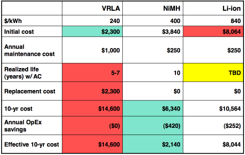
* PbPb, NiMH, LiIon cost comparison (from Ovonics).
Turquoise
Battery Project
* Mn-Fe: Lower voltage (~1.6) than MnMn -- but lower self
discharge.
* Gradual small improvements.
* Better case?: 4" ABS (or 6") - not the pipe, just the flat end
cap!
4.5" inner diameter gives 16 square inch electrode surfaces, 1/2 liter
volume.
Newsletters
Index/Highlights:
http://www.TurquoiseEnergy.com/TENewslettersIndex.html
Construction Manuals for making your own:
* Electric Hubcap Motor Building Manual
(latest rev. 2010/09/xx)
- the only 5+ HP motor that can easily be made at home?
* Turquoise Motor Controller Building Manual (latest rev.
2010/05/31)
- for the Electric Hubcap. (Probably there are commercial
controllers that would work, too.)
* 36 Volt Electric
Fan-Heater
(in TE News #22, 23, 25)
- if you're running your car on electricity, you'll want a
way to defog the windshield and keep warm. (This one I made - but you
can buy them.)
* Lead-acid batteries:
Sodium Sulfate 4x
longevity additive - "worn
out" battery renewal.
(http://www.TurquoiseEnergy.com/Na2SO4.html)
* Nanocrystalline
reflective rear electrodes to enhance DSSC Solar
Cells.(in TE News #28, 29)
* Simple Spot Welder for battery
tabs, connections (in TE News #30 - not the
best
welds, but article remains for ideas.)
* NiMH Dry Cells Pack Car Battery
(TE News #36 -
economical, very long life, green, lightweight: replace your lead-acid
battery!)
are all at: http://www.TurquoiseEnergy.com/
February in Brief
The 100 nickel-metal hydride D cells arrived on
the 3rd. I took 30 and soldered together the second
NiMH car
battery
the next evening. With 30 amp-hours instead of 22.8, it had plenty of
"poop" - the starter turned without the slightest hesitation, as easily
as with a brand new lead-acid, and continued to do so through the
month, even at
-6ºC. Mid-month I put together a second one,which I tried out in a
torque converter test. I'm taking orders now ($320).
Speaking of lead-acid, a reader reports that he
successfully renewed his dying boat winch battery last month with sodium sulfate salt.
There seem to be
surprising misconceptions about nickel-metal hydride batteries out
there, including by people who should know better. An electric bicycle
tech thought they weren't much good - even Chevron in casting odious
aspersions on them never went so far as
to say that! He said they wouldn't handle the
current. He said a 36 volt, 10 amp-hour lithium bike battery delivers
10 amps, has BMS circuits built-in, and costs $1000. I told him that
exact same size in nickel-metal hydride delivers up to 30 amps
continuous, needs no BMS circuits, and costs $320
from me. And I suspect it'll last longer. The only actual advantage of
the lithium seemed to be that it was lighter, 7 pounds instead of 11 or
12. (and for only an extra $680!)
I ran tests on a D and an AA Ni-MH battery, and sure
enough
they both met their amp-hours specs. The AAs are for some reason higher
energy density by weight than the Ds: 100
watt-hours per kilogram versus 75. I also tested a 15 year old NiMH AA
battery and
it still has 80% of its original amp-hours capacity. So I ordered 200
AAs to see how they fare in car battery packs... and how much work they
are to solder together. The small car battery - or bicycle or EV
battery - will weigh 9 pounds instead of 12. When economy is factored
in, NiMH AA cells would seem to be the best electric car batteries
available.
In motor developments, I painted rutile (paramagnetic TiO2
mineral) in sodium
silicate onto the first coils made with the iron powder coil cores.
Before and after measurements - on two motors to be sure the first
one wasn't just some fluke - appear to show
significantly lower
no-load currents with the coating, which I expect brings the motors
up to the fabulous 95% maximum efficiency target. (I haven't seen any
other motor claiming over 92% so far, though they probably exist.)
This simple but apparently
effective improvement to the state of the art of electromagnetic
materials fully justifies the nanocrystalline ceramic
coil cores project even though no whole cores were successfully made.
(And that's not
to mention the other offshoot, the nanocrystalline DSSC solar cell
reflective rear
electrode and process for making them!) The iron
powder cores - with the coating -
have the targeted low loss core characteristics. They are much better
than the
nail strip cores, with only one watt typical losses per core at 60 Hz
(EH: 1200
RPM) according to the manufacturer's figures.
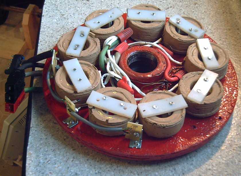 PP-epoxy stator, iron powder core coils, and painting the coils with
paramagnetic rutile,
PP-epoxy stator, iron powder core coils, and painting the coils with
paramagnetic rutile,
all contribute to very low no-load motor currents and consequent high
efficiency.
Early in the month I started winding motor coils with 20
turns of #11
wire. It became apparent that the $6 I'd paid for the old wire at
Ellice
Recycling would do all 27 coils for the new idea 26" rotor "Super
Electric Hubcap Motor", which I've decided is perhaps better named the Electric
Weel
Motor. ("EW"? "ElectricWheel.com" is taken) This bicycle wheel size,
low RPM, 15 KW
motor with an
order of
magnitude more torque than other motors should make a highly efficient,
direct to the wheel drive (via CV drive shaft) electric vehicle
feasible. This was one of my original design goals in the Electric
Hubcap project. I think it's the future of vehicle design. In
my head I ran through possible designs for the rotor and stator - and
then bought some materials and started building the rotor and axle/hub.
By the third week I
pretty much knew what would be needed and had bought or ordered most
the parts. Some details remain to be worked out.
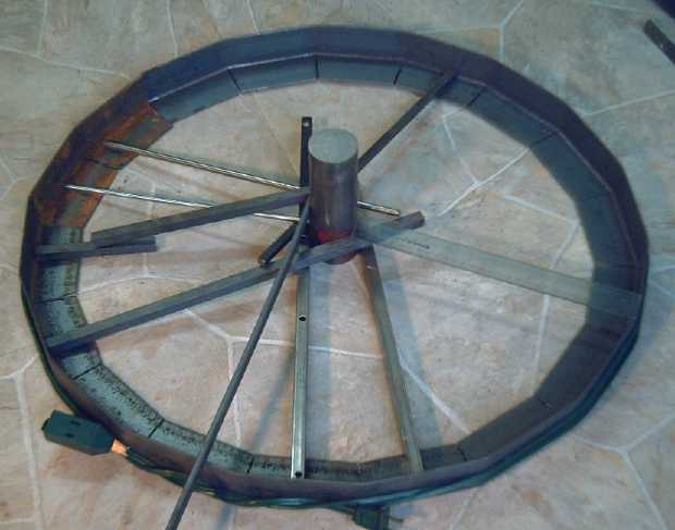
 26 inch rotor rim, stator hub and 2" diameter axle (compare with 1"
on left)
for the Electric Weel,
26 inch rotor rim, stator hub and 2" diameter axle (compare with 1"
on left)
for the Electric Weel,
to be
attached with heavy spokes or rectangular tube.
A few sample supermagnets are in position; coils
for the stator
(which attaches to the big hub on the top half of the axle) are shown
behind.
At the same time a
1988 Toyota 4runner with 446,000 Km on
it was available for a low cost from a friend and I bought it, as it
had sufficient
height under the hood to fit the proposed 28" diameter motor. Too big
for an add-on motor, this
will be a full electric conversion with the motor driving a front
wheel directly via its CV drive shaft. A new project - and a
potentially fabulous new product, tentatively dubbed the "Electric
Weel" - is born.
I am also making progress with making better chemistry
batteries and have some
hope that I might someday be able to give it considerable driving
range.
Otherwise... it's a 3500 pound truck and I'll be removing around 1000
pounds of gas engine stuff, so it can take the weight of some heavy
lead-acids, for potentially 60-80
miles max. range driving.
I might try NiMH dry
cell battery packs... if I can afford them. The spare Ni-MH
car
battery worked fine for a torque converter test in the car (along with
two
lead-acid). I think it would need around 2000 AA cells, perhaps $3000
worth. This would give 6000 watt hours - perhaps around 40 miles
range, with only 60 Kg (under 150 pounds) battery weight.
Perhaps prices will
continue to drop.
I went on something
of a "spending spree" this month, putting out well over three thousand
dollars for R & D supplies (and this follows on recently buying the
$3000 CNC machine) - scary stuff for a person with no steady income.
First there are two very promising new projects that require
significant resources: NiMH AA cells needed
testing as car and EV batteries, and the "Electric Weel"
Motor.
Then I wanted to buy ahead various things I'm almost certain to
need in the next few months for all the projects. I got 240 iron powder
coil cores,
100 NiMH D and 200 AA
batteries for the experimental car & EV battery projects,
72 supermagnets (36 for the Electric Weel motor alone),
electronics for motor
controllers, and a number of smaller purchases. ...not to mention the
truck! The reason for buying some items a little early is that
my corporate
year end approaches, and by buying them now, I get my SR & ED tax
credit a year earlier than if I wait until March or April. (Always
assuming the
projects are
again approved, of course. But are they not truly cutting edge?) I'll
use that to pay off the credit cards, and fortuitously my mother, who
has gone long and far beyond any reasonable requirements of being a
mother, has been able to send me some money at this time. (Thanks mom!)
There are still more things that
will soon be needed as the projects get more 'up-scale': version 2 of
the motor controller circuit boards, 11 AWG wire for winding more
coils,
more epoxy and other supplies, various chassis and frame parts, and
graphite sheets for more battery experiments.
Finally I got some
carbon rods and more (and doubtless purer) manganese oxide for
battery experiments for free (and already mixed with graphite!) by
'raiding' D cells from Rona's battery
recycling drop-off box. Ironic that throw away dry cells seem to be
mainly filled with
half of what it will take to make superb rechargeable EV batteries. I
also abandoned renting out a room to make space for an electronics lab
separate from the machine shop.
So I've gone out on a limb, but 2011 holds the promise of
Turquoise Energy having some
actual very fine products to sell: Electric Hubcap motor kits are
looking very close (though the market will be much larger if and when
the torque converter is working), and it appears that Ni-MH
batteries need only finding the right customers and soldering. Could it
be that one inventor might finally approach solvency through his work,
and
after 15 years of poverty level income?
New Electronics Lab
With the fine CNC machine
taking up 1/4 of the floor space in the machine shop/electronics lab
and a
growing inventory of motor projects and supplies for them, the shop was
getting seriously overcrowded, and the new Electric Weel motors will
take a lot of room. And the CNC router and lathe, though at the other
end of the room, make messes that aren't very compatible with doing
delicate
electronics work. My last renter having left in January, and anyway
having been
collecting rent only sometimes for the last two years from unreliable
people who couldn't pay, I finally decided to move the electronics
shop/lab into the now vacant room, also store some of the R & D
supplies
in it, and thus free up sufficient space in the machine shop to
rearrange it to work there safely and conveniently again. I now have
the garage, which has always been a shop, and three rooms dedicated to
R & D: the machine shop, the battery lab and now an electronics lab.
The difference in the machine shop was apparent the first
time I went to work: I wasn't stepping over things to get across the
room to the tools, and the workbench was clear since there were places
to put things away. I haven't yet found time to do any electronics
(ie, to look at the motor controllers) since the move.
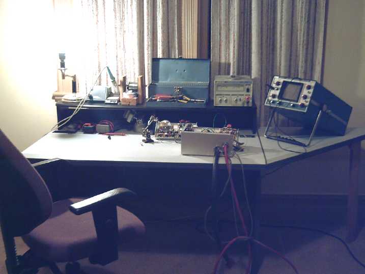 New electronics lab & workstation will be more conducive to
troubleshooting the accursed A3938 motor controllers
New electronics lab & workstation will be more conducive to
troubleshooting the accursed A3938 motor controllers
-- which promise to be excellent controllers once they're working right.
Electric Hubcap System & Motor Building Workshops
Rutile (Titanium Dioxide)/Sodium Silicate Coil Coating
For some time I've had the idea that coating coils with a
paramagnetic
material, even though it's a weak force, could help direct the magnetic
fields coming from the currents in the copper wire to flow more into
the
iron or iron powder of the core.
At the same time, TiO2 is a dielectric that
separates the coil interior from the outside.
It was intended that
such a coating be part of the nanocrystalline ceramic coil cores
project, which didn't get as far as coatings. Recently it finally
occurred to me it could be used just as well on
any coils.
First I tried seeing
if the magnetic
pull from a coil was any greater with the coating applied. It wasn't.
But the coil was activated by DC current - the motors were AC. I
decided to try painting the coating onto a set of motor coils and see
if
it had an effect on motor operation before giving up - it was still
possible it might reduce motor currents a bit.
The rutile and sodium silicate seem
to set by themselves with no other ingredients. I had
to break up a solid mass in the jar and add water to the old mixed
batch, and when this was painted on the coils, it seemed to just flake
off. If I mixed fresh rutile and Na2SiO3, they painted on and stuck
much better. However, the sodium silicate is still water soluble and
thus it's subject to washing off if the motor gets wet. Heat treatment
might "desolubleize" it, and I'll try that out soon enough. Otherwise,
perhaps some spray paint overcoating would make it permanent.
When I tested the
motor before and after painting on the
rutile in
sodium silicate, I got the following approximate (and rounded off)
readings
of no load
currents with a 30 volt supply:
500 RPM 1000 RPM Spacers
With the uncoated coils
2.5 A 4.75
A 0 (.55" flux gap)
2.0 A 4.0
A 1 (.675")
1.5 A
3.5 A 2 (.79")
coated coils:
1.5 A 4.0
A 0
1.0 A 3.0
A 1
1.0 A 2.5
A 2
These were very significant reductions! I decided I should
try and repeat the results before I got
too excited. Three weeks or so had elapsed between the 'before' and
'after' tests, and I had
changed the magnet sensor mountings. In the 'before' tests I got
somewhat different current for clockwise versus counterclockwise, which
didn't reoccur in the 'after' tests. (The 'before' figures above are
for the
lower current direction.) Were the results skewed?
Tristan's motor, the
last one made with the finishing nail strips coil cores, was still
here, so I decided to work with it. Again, in the 'before' tests, the
motor drew more current spinning one direction than the other. (almost
double!) The lower current figures are again shown. In the
'after' tests, the current was the same in either direction with the
widest gap, but not with the lesser gaps. I can't say I understand the
discrepancy, but some evening out happened with both motors when coated.
Note that the flux gaps were different before comparing
the absolute currents below to the above figures. (Also, owing to a
crooked magnet rotor, used for all the tests, they are at best an
approximation. The Dexter trailer axle flange is to blame for that.)
I poured some liquid off the top before using the more
pasty stuff
in the original jar for the second attempt.
I didn't want to
remove the coils and un-wire them, so I just loosened the clamps. I
didn't get at the undersides very well with the paint brush. So slight
further improvement should be possible. These coils were dipped in flat
black paint, so I expected the rutile would stick to them much better
than to the
slick epoxy of the new coils. However, there was still a lot of flaking
and crumbling.
500 RPM 1000 RPM Spacers
uncoated coils
2.5 A 5.75
A 0 (.675")
1.75 A
4.0 A 1 (.79")
1.25 A 3.0
A 2 (.9")
coated coils
2.1 A 5.25
A 0
1.5 A 3.75
A 1
1.1 A 2.75
A 2
Evidently, the coating helps as I had anticipated, and the
motors probably now achieve their 95% efficiency target. This would
appear to
constitute a noteworthy advance in the state
of the art, being potentially useful for
transformers and other electromagnetic devices as well as for motors.
Now it's known to work.
What remains to be determined is how thick the coating should be, and
perhaps the optimum composition. Niobium, the element below titanium on
the periodic table, is the most paramagnetic - but also quite costly.
Sticking with rutile, is it
a case of "the more the merrier", or is a micro layer as good as a
millimeter thickness? I can paint another coat onto my motor before I
reassemble it... when I have time.
It's also to be determined whether it would pay to put on
a "primer" to help the mix stick, or an overcoat to protect it from
moisture during operation. But these are just matters of technique.
Also Noted...
A couple of other things were noted in the above tests
besides the coatings.
First, comparing
currents with similar gaps
in both sets of 'before' tests also shows that as anticipated the
toroidal iron powder cores seem to have substantially lower losses than
the
solid cylinder ones made from nail gun finishing nail strips. It is
possible that they would be comparable to toroidal finishing nail strip
cores, but since they're ready-made, I'm unlikely to try the experiment
unless I really want to try out optimizing the shape and amount of iron
rather than just using a toroid. But 95% efficiency will be very hard
to improve on. The law of diminishing returns says "drop it!"
Second, I changed the magnet sensors so their positions
could be shifted easily. However, moving them back and forth made no
noticeable
difference to operation or current - at least not at 500 RPM, which is
1/4 speed.
I've seen writings describing advancing the timing to optimize
performance a bit at one RPM in one direction (and worsen it in the
other direction). I
think they really only apply with high RPMs/frequencies and higher coil
inductances, both of which are very low in the Electric Hubcap motors,
making for wide tolerance.
Series Wound Coils - Epoxy
Until now I've been winding the coils with 60-63 turns of
#14 AWG wire. The three coils of each phase are wired in parallel. I
recently got ten pounds of very old (WW II era? 1950s?) #11 AWG magnet
wire
for a dollar a pound, and I decided to try winding coils from 20-21
turns of this. The three coils of each phase would then be wired in
series to make up the 60 turns. I made a winding spool that put 7 turns
in each layer. The coil turned out just slightly larger in diameter
than the #14s. Part of that is the old fiberous insulation is almost
1/100th of an inch thick instead of 2/1000ths for modern coatings.
With modern #11 (tried when I ran out of the surplus
stuff with an odd number of coils made), I can squeeze in 10
turns per layer and do it in just two layers, which uses the least
length of wire and makes the most compact coils of all, and also proved
to be the
easiest by far to wind.
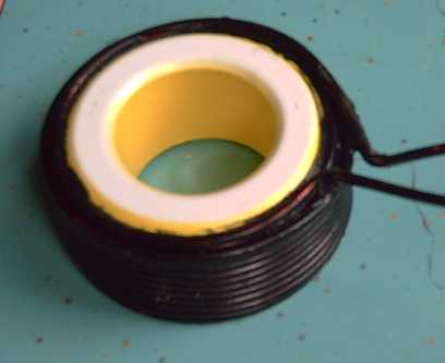 Coil with 20 turns of modern #11 AWG wire in just two layers (before
rutile
coating).
Coil with 20 turns of modern #11 AWG wire in just two layers (before
rutile
coating).
Most compact, easiest to wind, lightest (360 g), and best heat
dissipation.
These coils were also lighter than the #14 coils - 370
grams versus 425. The overall wire gauge is a bit lighter: 3 #14s works
out a bit smaller than #9. But I expect #11 is heavy
enough: since it's wound in just two layers,
the heat has little volume for its radiant surface area. However,
copper resistance for an EH motor from tables (#11 =
.00413 ohms/meter) works out to .10 ohms instead of .063 or so, so
copper losses at very heavy loads are bound to be higher. The trick is
to avoid working the motor so hard that that matters much. The rutile
will help.
I made a second winding spool so I could have two coils
going at once to make them faster. Then I ran out of the high
temperature epoxy I bought in 2008. I bought a different kind that also
said it was "thermally conductive". That should be still better to get
the heat from inside the coil to the surface for cooling. However,
although it
said it would dry in a 65ºC oven in an hour, the same as the
previous type, it took more like 3 hours. I had to redo parts of four
coils that came unraveled after 'only' 75 or 100 minutes in the oven.
Now even with two spools the speed I can make them at is reduced - ya
jes cain't win! I will of course make more spools whenever I'm waiting
for coils in the oven and have nothing else to do. That last hasn't
been happening to date.
Stators: Back to trailer wheel hubs
In making the polypropylene-epoxy stators, attaching the
bearing hub in the center is one problem, and having the flat rotor
disk bend into a dinner plate shape with the attraction of the coils to
the magnets on the rotor is another. If instead the stator plate were a
ring that bolted onto a trailer wheel hub, both problems would be
alleviated if not solved, and the metal of the trailer hub would be
inboard from the magnets on the rotor and not a significant source of
magnetic drag.
So when I went out to Thomcat Trailers to get great big
axle bearings for the giant rim motor, I also bought a new hub to try
out with the smaller ones. The PP-epoxy ring stators with trailer wheel
hub will be a project of the near future.
One for motors with in-line torque converters may still
need to be cut down to fit two hubs on one axle, and (not cut down) it
adds four pounds to the motor weight, but as it solves the
PP-epoxy stator mounting problem and (pretty much) ensures proper
alignment, and as I had to turn both sides of the pipe fitting hub -
extra labour -
that (and the $35 price) seems like a bearable trade-off.
Electric Hubcap Motor Kits are getting close
Producing
stators in quantity was the last large question mark in my head - with
trailer hubs and just flat rings of PP-epoxy, now I know pretty much
how every part is to be produced. I can
see the day of offering a complete motor kit drawing close! Of course,
the market for them will be much larger once the torque converter has
them moving cars.
Also the Electric Weel motors, once a couple of prototypes
have been built, shouldn't be too far behind since they use the same
electromagnetic parts - the same coils, magnet sensors and magnets.
Many of what are likely to become production structural parts are also
coming together or have been identified. And the "EW" motor doesn't
need either gears or a torque converter to move cars!
The Electric Weel
- or - Super Electric Hubcap Rim Motor:
The Car Motor of the
Future
Propulsion needs and conundrums
It goes almost without saying that elimination of the
gears and transmission and their 30-40% typical losses would be a major
improvement to vehicle efficiency. But to turn a car wheel directly,
1:1, requires very high torque, and seemingly to get that torque
would require a greatly oversized electric motor with far more power
than is
otherwise actually needed.
For example, the Electric Hubcap motors are quite "high
torque", but still almost an order of magnitude too low. Four of them,
one directly
tied to each wheel,
would give four times the torque of one. It would be 20 KW... and yet
it still
wouldn't be enough torque to accelerate rapidly or start up a hill.
Doubling the rotors and
stators
on each motor would make it sufficient, giving 8 times the torque...
and
would total 40 KW - way overpowered. (and a couple of hundred pounds or
more.)
On the other hand, a simple fixed gear reduction to
sufficiently
multiply the torque of a smaller motor produces serious inefficiencies
in itself, and it creates the problem of very high
motor RPMs at highway speeds - leaving as options small,
high RPM motors, or the nasty multi-gear transmission.
The torque converter, constant velocity transmission (CVT)
or other efficient variable
reduction mechanism is a potential practical solution, but since
Constantinesco's successful 1926 car, practical working units have
remained elusive. (...so far!)
Motors that produce their power at too high an RPM with
insufficient torque for direct car wheel drive, and unsatisfactory
technologies for changing that rotation to lower speed and higher
torque... These are the
problems and
parameters everyone has been grappling with in the creation of vehicle
drive systems. But we have all
unwittingly been thinking inside a cramped box!
Escaping the Box
When we design a motor, we intuitively want to fill
the entire stator and rotor volume with 'appropriately proportioned'
coils and magnets to maximize utilization of the space and power per
volume. There is the
root of the box: implicit assumptions about how to make motors,
limits the size and shape of the motor
we want to make -- to dimensions unsuited to electric vehicle drives.
But why do we care what inner space is 'wasted'? - torque
is
what's
lacking, and the maximum torque is developed by placing the force
elements
out by the rim of as large a diameter of rotor as is needed, maximizing
rotary leverage from the force to the axle. All that needs to happen
inside
from that force producing rim is to connect it to the axle.
The Electric
Hubcap's simple, flexible axial flux design
provides the key to escaping from the box. By simply tripling the
number of the same propulsive elements
and placing them all around the outer rim of one Electric Hubcap
type motor, the torque radius is also
tripled. Three times as many force elements at three times the radius
from the axle provides nine times the torque with only three
times the
power, 15 KW. That's more torque than from all four doubled regular
diameter motors combined (40 KW).
And the maximum RPM of this "bicycle wheel" motor is also decreased
threefold, becoming about the same as that of a car wheel at highway
speeds. The ideal fixed "gear ratio" is thus one to one. This is
the ultimate, simple vehicle drive solution -- it's how tomorrow's far
more efficient electric cars will be made.
Of course, this motor is as large a diameter as a wheel or
larger. How is it mounted so it doesn't drag on the ground? The
answer is of course to turn the wheel via the regular front wheel drive
CV drive shaft. These already attach misaligned transmissions to
front wheels. The motor can thus be mounted somewhat higher up, and
(depending on the
geometry under the hood) could probably even be
mounted at an angle to eliminate the inner CV joint.
Of course, mounting the motor under the hood means converting
the car from gasoline to electricity rather than turning it into a
plug-in hybrid with an add-on motor, so I'll be continuing the
original Electric Hubcap/torque converter project. But this larger
motor will make fabulous conversions, and
it also points the way for new car manufacture.
"Plug-in hybrids" could possibly take the form of a small,
efficient gasoline
generator that can be plugged
into a compartment somewhere in the car to charge the batteries during
long highway
trips.
Electric Weel Truck Conversion
After winding nine coils, I realized that I had enough of
the old #11 wire to wind 27 - the number needed for the big 9 x torque
"Super Electric Hubcap" idea.
This seemed to fit with a friend selling a very high
mileage 1988 Toyota 4runner truck cheaply: it would surely fit such a
motor
easily under the hood for an all-electric conversion. So I decided the
project was ON! I bought it
and wound all the coils. (and I now have 18 extra in case anyone wants
to build a motor, and will make more if
requested - $10 each.)
It seemed like a good project in itself: the regular
Electric Hubcap with torque converter would be a good city motor, but
at only 5 KW would surely at best be a marginal performer on the
highway. The triple would be 15 KW. (Of course, these figures should be
multiplied by at least 1.5 to make them comparable to systems that
drive
the wheels through a transmission.)
It also seems like a good "failsafe" project with the
torque converter project dragging on and on without actual success so
far. In spite of the structural parts 'upsizing' and other needed
changes for
such a big motor, it
has excellent
prospects for moving vehicles using all the 'proven' Electric Hubcap
motor and
controller electronic, electrical and magnetic parts that already work
- just three times as many of each.
Motor construction details started solidifying in my mind
out of a host of possibilities. 1/4" or 3/8" square or round steel
bar/rod
might make nice spokes. For the magnet rotor, the rim could be 1" x 2"
x
70" of angle iron. The 2" face would be cut apart into 18 equal
segments, 3.9"
long. The 1" face (uncut) would be bent around into a 'circle' of 18
straight segments with the 2" flats sticking outward. Thus the inside
of the rim will be a 1" vertical wall to provide vertical stiffness.
The spokes will attach (welded) to that. The eighteen 2" x 3.9" flats
will mount the 36 magnets, 2 per segment. For the hub... [was I really
going to use those 1" trailer axles, and those little pipe coupling
hubs, for
such a big motor, directly turning a truck wheel?!?! Metal fatigue!!]
The 27 coils weighed 10 Kg, 22
pds. That's
almost the whole weight of the regular size motor, right there! I'm
hoping to keep this thing under 100 pounds.
It may seem odd
using such small coils around the rim of such a big motor. This big
motor would fit much larger coils and magnets, for
example one could use 18 larger coils, or 9 huge ones. That's our
habitual 'inside the box' thinking, trying to make a more powerful
motor rather than "waste space". Using
the same
components as the smaller motors has advantages:
- All the forces act as close to
the outer rim of the motor as possible. This maximizes the torque for
the power, giving the "9 x" torque figure with only a 15 KW motor.
- The electrical systems are exactly
the same as with the regular motor. The tested, working components are
all simply triplicated. This saves working out whole new sets of
component values and operating parameters.
- Using identical components also
avoids having to design and stock multiple versions of everything - the
same coils, magnets, motor controllers, wiring, plugs and everything
will fit any of
the motors.
- I wouldn't want to have to deal
with bigger supermagnets by hand.
A 1600 Kg/3500 pound truck may seem a pretty big vehicle
for an electric conversion. But once I've ditched the engine,
transmission, rear drive shaft, muffler and exhaust pipes, gas tank and
fuel pump, radiator, and a couple of heavy underside protection plates
that won't be needed, it should be headed for 1000 pounds lighter.
That'll give it carrying capacity for 100 pounds of motor and
triple motor controller... and whatever weight of whatever batteries
are installed.
On the 17th I bought 26 pounds of steel at Metal
Supermarket to make the main
structural components from. I couldn't get 1" x 2" angle iron, so I got
2" x
2". Just as well - 1" would have been rather feeble by proportion. On
the 20th I
cut 20º angle wedges from it with the angle grinder zip disk and
bent it into a circle. Originally
I was going to
have the vertical on the inside, but then I realized it would be
stronger with it on the outside and easier to weld the spokes on, and
also
that the other way, it could severely injure one's fingers if they
accidentally contacted the ragged outside of the spinning rotor. The
angle
joins could also be welded solid, and even loose they couldn't bend
around.
The change meant
the piece I bought wasn't quite long enough, so I got a
little piece to weld in, courtesy of Urban Iron.
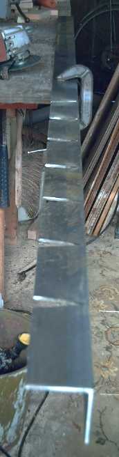
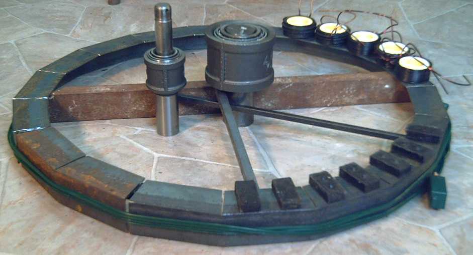
 The 26" diameter rim of the magnet rotor: a 2" x 2" angle iron
divided into 18
sections, each bent 20º to form a rim - to be welded.
The stout axle in the middle is 2" diameter and 6" long.
Hub & 2" axle, turned on the 26th to fit the 5000 pound, 1-3/4"
I.D. trailer
bearings.
(Regular motor hub & 1" axle are shown to its left.)
I'm leaning towards six pieces of 1" x 2" tube (rusty piece shown) for
spokes
rather than many pieces of small stuff.
Also of note: 36 supermagnets, represented here by some
supermagnets,
and the 27 coils as they'll be spaced, but which of course will go on
the as yet unmade stator, not on the rotor.
The next day I found some pieces to cover the axle (the exposed
bottom half here),
and weld the inside ends of the spokes to.
Mechanical Torque Converter (MTC) Project
I finally tested the "5 star clock escapements" converter
version made in December. It barely moved the car.
The videos showed the linkage to the wheel was much better
- no more of the output rotor bouncing back and forth.
Something is still amiss with the motor and
controller. Running in reverse, the motor drew under 20 amps and didn't
get up much speed. In forward, it often had to be pushed to get it to
start spinning. Then it would read 40, 50 or even 60 amps, and yet
seemed to have even less power and speed than in reverse. This
asymmetry between directions really leaves me scratching my head, and
this time is by far the worst ever. (Could I have connected the phases
wrong?) I'm going to see if I can
get the new stator to fit with the
rotor and axle that have the torque converter, and see how that
performs.
Notwithstanding all that, even with lower motor power the
car should move. I began to realize the design was still violating one
of the basic operating principles of the mechanical torque converter.
All five escapements now operate in unison and that's much better than
staggered. But there are 25 teeth on the outer gear - continuous all
the way around. What it needs are 5 evenly spaced teeth that work in
unison... and 20 'empty spaces' where no torque is developed, where the
motor gets to build up its speed freely between torque pulses --
whether or not it has all the power it should have.
The simplest thing to try is to remove the ring gear and
replace it with five triangles evenly spaced around the rim of the pan.
I no longer see either the escapement shapes nor the layout as anything
like optimum, but it has a very good chance of working. (A more optimum
layout would put the escapements on the outer drum and the fixed points
on the inner.)
Now that I've thought of it, it seems silly. When I had
the teeth sideways, which caused more vibration than torque, I had this
aspect right: four sudden hits per rotation, all four pins hitting at
the same time. When I oriented the teeth on axis and changed the
masses to escapements, somewhere I lost the whole principle!
It seems that the
motor slows down quite a lot with
each hit. Another thing I want to try is to add weight to the motor
rotor so it has the inertia to barge right on through.
Things to try next:
1. Change the stator to the new one and hope for more power. If fitting
it proves to be simple, it's the thing to do first. It's more
efficient, but it may or may not provide much more actual power.
2. Make a 'ring gear' with just five teeth - 20 'missing'. Giving the
motor more slack time to gain speed is likely to be effective even
without
more power, and should be the next thing to try. I might have made it
in February but the weather turned cold - even the shop in the house
was too cold to work in for a week or so.
3. Change the motor controller
for more power. This requires getting the A3938 motor controllers
working properly.
4. Add inertial mass to the motor rotor. However, the resulting
improvement is likely to relatively minor: the hits won't slow the
motor as much, but it'll also be harder to speed it up again between
hits. Item 2 is the thing!
At the same time, I've been playing in my head with designs for
improved tooth
shapes. A concave shape, like the front side of a
water wave, would cause the escapement to accelerate continuously as it
moves up the slope. This would be smoother and quieter than 45º
'impact' hits. And it would wear more slowly.
Ni-MH Dry Cell Car Battery Project
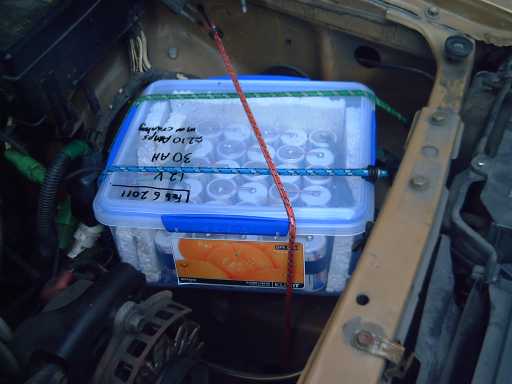
NiMH
dry cell battery #2 (as initially mounted) under the hood: 30 AH, 30 D
cells.
This is the best
performing battery I've ever put in the car - starts great even at
-6ºC!
It's under 12 pounds - the
car is 30 pounds lighter!
I simply used a plastic food container to keep the weather and dirt out,
and stuffed in some styrofoam around the edges as it was too large in
all dimensions.
These work great, so I'll start off with a Car Batteries for Sale
ad:
30 AH (210 amps cranking, small car) - $320
40 AH (280 amps cranking, mid size car) - $420
Custom configurations (any voltage, current) - $proportional, nothing
extra for being custom.
Individual NiMH cells:
10 amp-hour D cells: $12 each
2.5 amp-hour AA cells: $3 each
(End of advertisment.)
Correction #1: Last month
I reported that someone had used NiMH dry cells to
rebuild his Toyota Prius hybrid battery. Evidently the correct story
was
that
the person disassembled his Prius battery and that's what was already
in it,
straight from the manufacturer. So! Long lived NiMH hybrid
batteries
consist simply of a string of 120 or more (depending on voltage) NiMH
dry
cells, evidently some are 7 AH to 10 AH "D" size - the very cells
I'm using!
This lends great support to the idea that the same cells will have
very long lives as car batteries. And it's worth noting that these
[dangerously] high
voltage batteries simply have (AFAIK - I *could* be wrong) two
terminals at 0 and 144 volts
- there are no extra "battery management systems" regulating each 12
volt section as is evidently required with lithiums.
Correction #2: A reader of the
last TE News told me
he himself had experimented with making a NiMH car battery 15 years
ago. I just knew I couldn't have been first with something so obvious!
But I still can't find any references to the subject on the web.
He mentioned
problems that cropped up in his trials, which
I think
won't happen now because of improved cells since NiMH's early days and
because I cross wire, parallelling at least every second group of cells
to
support any weak ones, now for the D cells version parallelling at 0v,
1.2v, 3.6v, 6.0v, 8.4v, 10.8v and 12v with an alternating up-down 5 x 6
cells layout that needs no additional wires for that. (see images
below.)
The worst of the problems occurred at low temperature. He
mentioned -6ºc. Most new cells are rated to -10ºc, and
-30ºc cells are available. High temperatures seem to be no
problem, except gradual self-discharge increases with temperature, as
it does for most types of batteries.
(Someone else also
reports having used just two banks of 12 Ni-Cd 5 AH D cells to start a
car with a dead battery out in the middle of nowhere, and that just 1/2
dozen would start a VW Beetle.)
Large Flooded NiMH Cells
He also mentioned Ovonics flooded NiMH batteries, and gave
me a
link to some info. It's the first time I've ever seen a price for
Ovonics batteries, and if correct that 223 $/KWH price
definitely puts the
lie to
the assertions of those who killed it that "nickel-metal hydride is a
great
technology, but it's so expensive." These things should be all
over at Wall Mart and Canadian Tire, since 2005 or so, displacing
lead-acid and propelling the shift to electric vehicles.
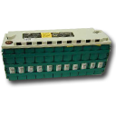
Ovonics liquid filled 13.2 volt (11 cells) NiMH
battery: 85 AH, 1120 WH, 60 WH/Kg.
Said to be $250 list price, but never available to the public before
'big oil'
murdered it.
So far it's nearly twice the cost for this capacity in NiMH dry cells -
but still price competitive with lithium-iron phosphate, and
dropping.
A good thing that may gradually emerge from this is that
the dry cells are actually better:
1. higher energy density for
greater driving
range.
2. maintenance free
3. safer - no potential
spills of caustic alkali
NiMH dry cell prices are likely to drop substantially as
they spread into
more automotive applications, finally, we may hope, attaining a similar
price range
to the
flooded cells. They would never achieve the sort of sales volumes
necessary for this if the flooded cells were available. "All things
work together for progress."
I do see flooded
NiMH cells available on one web site for the first time, from China: www.ChangHong.com .
These seemed to have similar energy densities to the Ovonics. I didn't
ask about the price since the dry cells are better. The dry cells are
also made in China, though I'm
ordering them from a US company. India is experimenting with NiFe
(even cheaper very long-life chemistry) dry cells for telephone
exchanges. Again we
see the Far East forging ahead with advanced battery technology that
has been stifled and suppressed here in the West. And lest we think the
suppression of batteries is anything new, someone has told
me that nickel-cadmium dry cells were kept out of North America for
over half a century by the well known makers of non-rechargeable dry
cells here. The Germans used them in submarines in world war one.
30 AH D Cell Car Battery
Meanwhile, back at the ranch... I put together the first
30
AH D cell battery on the 4th
after the cells arrived on the 3rd. I made a frame to hold them in
place, and again I simply soldered them. (this time wearing safety
glasses just in case. Not only potential bursting of a cell, but a
solder splash in the eye would be very bad, and I did have a wire
spring up and flick up solder as it melted.) I decided to wait and see
how many batteries I
actually end up doing before going to the trouble of making a discharge
welder and setting up the CNC machine to weld tabs. Also, with the high
currents of starting cars, it seemed prudent to use heavy, copper wire
and plenty of solder to ensure good, strong connections, rather than
thin nickel-brass tabs. All bets are off for the AA cells,
though - all those little cells will take a lot of soldering, and the
currents through each
cell are much lower. On the other hand, smaller, stranded wires and
small cells are much
easier to solder.
I terminated each of the three banks with a wire soldered
to a "_n_" (or "Ω") shaped piece of copper bar. A nut tightened the
copper bar's
"n" center between the head of the 3/8" bolt and two washers, one
inside the plastic case and one outside. The rest of the bolt stuck out
to attach the car cables to with another nut and washer. (Yes, a
close-up would have been nice!)
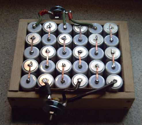
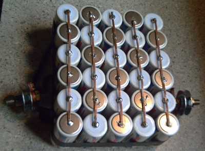
New 30 AH D cell battery
L: In cell holding frame of Garry Oak sapwood
R: Bottom view shows the rest of the connections.
As I now had the first Ni-MH battery to carry as a spare for a couple
of weeks in case of any problem with the new one, I finally carted the
old lead-acid battery away to renew it. It weighed 43 pounds, so the
new Ni-MH battery makes the car over 30 pounds lighter!
One thing I didn't think about is that while
they'll work fine in the car, and jump starts from a running car should
work fine,
'intelligent' lead-acid battery chargers are unlikely to give
good results, since they expect very specific voltages at specific
states of charge and will most likely shut off without giving the
NiMHs much of a charge at all. In lieu of an actual 12 V Ni-MH (or
Ni-CD) battery charger, any "dumb" charger, or even an unregulated 12
volt power adapter (these are usually closer to 15 volts), is likely to
give
better results. I bought a "semi dumb" one that the salesman said was
"dumb". It works but it isn't as good as "dumb". It charges them at the
full 2 or 6 amp selection, but never reduces it and has to be shut off
manually since it can never raise the voltage to the 15 volts it wants
to see before it says "enough!" With the really dumb ones - if any
still exist - the current drops off as the battery approaches 14 or
14-1/2 volts.
D & AA Cell Performance Tests
Somebody said they didn't think they were getting the
rated amp-hours out of their NiMH AA cells. On the 16th I decided to
test a D cell to see if the performance specs were exaggerated. I
started at 8:00 PM with a .5 ohm load. That would be 2.5 amps at 1.25
volts. Since the voltage drops off after about 90% discharge, I
expected it should drop below 1.00 volts out (the usual cutoff point)
between 11:30 and 11:45. But it took until 12:34, an hour longer than
I'd anticipated. It would have run a lighter load still longer.
It appeared it had put out 11 amp-hours, but later I found
that the alligator clip leeds had considerable resistance, making the
total load perhaps .575 ohms. This would make it about right for the 10
AH rating.
But perhaps in the competitive quest for sales, AA cell
ratings were exaggerated? After all, I had seen two 120 volt motors
with ordinary 15 amp plugs the same day I tested the D cell, and one
earlier, all claiming to be "3 HP". It is impossible to get more than
about 2 HP (rarely that much counting motor inefficiencies) from a 15
amp, 120 volt outlet without blowing the breaker, so those claims must
be extreme exaggerations, not to say false or misleading advertising.
The ratings on the AA cells gave them up to 100 WH/Kg,
versus 75 WH/Kg for the D cells. What was the actual case for the AAs?
If in fact they were no better than D cells, that would eliminate the
idea that using AA cells could provide the highest energy density for
electric cars at the cost of a lot more soldering. Would all that
soldering prove to be for naught?
The way to find out would be to test a new AA cell, which
I did on the 20th with a 2 ohms load. Disappointing performance turned
out to be a high resistance (.1 ohms or worse) on the battery holder
connection. So I started again with another cell, this time with the
tab wires soldered on so that only the clip leeds were wild cards. (I
finally determined they were around .1 ohms too.) The test ran 3-3/4
hours and showed the cell did indeed have the rated capacity.
This means that the AA cells truly are the best for
electric transport, offering 100 watt-hours per kilogram for about the
same cost per KWH as using D cells. With a large surface area per
volume, they weren't likely to need any form of cooling either. The
only drawback is the amount of soldering needed for all those tiny
cells.
I've heard of electric cars being done with "3000 AA
cells" and wondered why D size wasn't chosen. Evidently the builders
did their homework!
For regular car batteries, I'll have to cost out the
economy of spending about 3 times as long soldering versus any savings
in cell costs -- but also factor in the appeal of a 9 pound car battery
instead of 12 pounds. Compared to 30 or more pounds for lead-acid it
seems a bit academic, yet "1/3 the weight" or "30%" sounds better than
"2/5 the weight" or "40%".
Finally I decided to test one of the NiMH AA cells I
bought in 1996 to see how close to it's rated 1.6 AH it would come
after 15 years. (The digital camera I bought them for is long gone!) It
has been much abused by overdischarge in battery clocks. The clocks run
fine until the battery is down to about .5 to .7 volts. That means
every time the battery runs low it runs for weeks or months way under
the 1.0 volt recommended minimum voltage.
Again I used the 2 ohm load. The test showed that the cell
has at at least 80% of its
original amp-hours, but that its ability to supply heavier currents at
rated
voltages has been much reduced. (I would have to run a test at a lower
discharge rate to ascertain amp-hours more exactly.) Evidently it'll
run a clock
as long or nearly as long as new, but it's no longer very good for
heavy loads.
In car use the batteries don't get left run down for months like
that, and in
spite of occasionally having to put out a lot of current, they'll
probably fare better. "Life of the car" is what Ovonics says of NiMHs.
Finally, here is a sample cost graph from Ovonics. It's
probably reasonably representative, with the cost of NiMH being not far
below the bulk AA cell price. The life spans given would be for
heavier
cycling rather than for gasoline car battery use. The annual
maintenance cost of dry cells is about zero.
Turquoise Battery Project
While it was thrilling to replace my lead-acid car battery
with 1/3 the weight of NiMH dry cells, I was also encouraged by further
tests on January's second try at my own new chemistry battery, which
showed I finally had a real cell, even if the specs were abysmal owing
to high internal resistance. I ran it for 24 hours on the 5th/6th with
a 26 ohm load. The voltages were very low and got worse (from 1.6
volts, 50 mA at the start, to 1.1 volts/40mA after an hour and ending
at just under 1/2 a volt/17mA after a day - headed for an amp-hour
altogether). But the voltage drops were very gradual and it continued
putting out current the whole time, and would have continued probably
for another two or three days - at ever lower voltages.
It also charged back up in a day or so, and a second load
test produced much the same results.
After that, I opened it. I remember putting in enough
water to pretty much flood it, but as I suspected, it was more of a dry
cell. I added water, flooding the top part (which may or may not soak
into the bottom electrode leaving it still un-flooded), cleaned the top
graphite sheet, and put it together again. Charging voltages had been
going up beyond 2.5 volts, now they were a little lower.
But it occurs to me that much of the resistance of carbon
terminals is contact resistance. I think I need to make "ligatures" or
find little pipe clamps to go around the whole carbon rod and make
contact at numerous points.
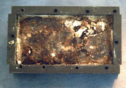
February's Battery Cell
I emptied and
cleaned the other 1.5" x 3" cell case, cleaned graphite sheets with
hexadecane and epoxied "D" cell carbon rods to them when I had mixed
epoxy for doing motor coils.
On the 7th I mixed the positrode: 30g "B mix" and 6g
graphite. Recalling that
cobalt oxide was used to improve conductivity of nickel
hydroxide/alkaline
electrodes, I added 1.1g Co2O3. (I only meant to add .3g, but the first
lump was 1.2 and I couldn't seem to extract much of it from the mix.)
On probing the loose powder, it typically gave readings in
the range of 15,000-50,000 ohms. This time, I would have some vague
idea whether that sort of loose powder reading might turn out to be a
5000 ohms electrode after compaction, or 50 ohms, so I might better
estimate the amount of graphite necessary for next time. I added 2g
Sunlight and about 4-5g water, mixed, and compacted. Contact
resistances were around 100 ohms. 50 would have been better, but 100
seemed alright.
Later, after I had it in the battery, it read 35-50. I got
out the commercial Ni-Cd electrodes, still in jars in the cupboard for
comparison. A Ni one read mid 1s of ohms, a Cd one under 1 ohm
everywhere. These were very thin electrodes sintered onto perforated
nickel foil, which was welded to the terminals - that's why those tiny
cells would put out 20 amps! If only some metal would last in the salt
electrolyte! It drives home the very low resistance requirements for
getting high current cells.
Of course, I can add all the graphite I want to bring the
resistance down to the teens or even ones. What's optimum? And I can try
adding monel to the negative mix. Perhaps I'll do that by pulling out a
graphited negatrode and replacing it with one having monel instead.
That can bring the negatrode resistance down to 1s of ohms, if it
lasts. which it might. On the other hand, carbon is light, fluffy and
cheap; monel is dense, heavy and while not prohibitive, it's less
economical.
For the negative, I ground up an "old" one (early January)
that read
around 500 ohms and hadn't been used for that reason. The loose powder
read
megohms. I added 2.5g graphite and the readings were 10s to 100s of KΩ.
I added another 2.5g and they were down to lower 1s of K. Then I added
2g Sunlight and 4g water. The mix was clearly too damp, and I added 4g
manganese powder. Total was 47 g of material. When compacted,
resistances were in the desired 50 ohms range. I painted in some
eggwhite and water, and cooked it in the oven for 75 minutes at
110ºC/225ºF.
Then I took the positive, which had also been drying in
the oven, and quickly ran the propane torch over it to sinter the
surface. (I don't think that's necessary with the negative.)
Both electrodes were about 5mm thick.
I remembered how long the last negatrode had bubbled when
the water was added, so this time I decided just to put it in a bath of
water. And the positrode too while I was at it. The "+" started
crumbling from the corners, and the "-" swelled up like a sponge.
Evidently this wasn't a good idea for either one of them! I took them
out. I put the "+" into the battery, scooping up the powder and filling
in the corners with it, and set both in the sun (there was some! for a
while.) to dry. After that I re-compacted the negatrode, and put the
calcium hydroxide layer on the positrode.
Additions
Was there anything besides cobalt I'd forgotten about that
might be useful? I started checking past notes and ran across the
reference to zirconia again, and
realized the zircon layer had got dropped somewhere in all my
un-methodical
experimentation. A layer of zircon(ia) on the separator sheet evidently
helps prevent migration of cations - one more technique that can be
applied - as in this V-Fe alkaline
(non-rechargeable) cell:
Given that most battery researchers simply avoid all
soluble materials for rechargeable cells, and hence cast away many
valuable and energetic reaction possibilities, the reader must forgive
me for throwing up all the roadblocks to electrode cation migration I
can think of or find in each cell. Basically I think chelation,
binding dissolved cations into a matrix, should allow the use of
soluble ions. Even so, potassium permanganate is only slightly soluble.
I wasn't quite sure where to put it amongst all the other
layers. I finally decided to paint it on bottom of the separator paper
with acetal ester, that is between the positrode calcium layer and the
paper - perhaps separated with cellophane. The
Fe2O3 could go on the top (negatrode) side.
I had good hopes, but the battery didn't perform as well
as January's second attempt, and the case sprung two leaks. I set the
project aside to work on other things.
Self Discharge
My batteries still have serious self discharge problems.
Whatever their voltage is supposed to be, they drop rapidly to around a
volt, and thereafter only slowly.
It's the other main remaining problem besides high internal resistances.
One day I raided Rona's battery recycling box and
collected discarded alkaline cells to get the manganese-graphite mix
out of them, suspecting they would be more pure than the MnO2 from the
pottery supply. Still, I don't know the true source of the problem.
Would the self discharge be cured by purer manganese? Probably not but
it's something to try.
I took apart a square lantern battery, and found it
contained
four 1.5 volt F cells. The cells were connected with soldered wires:
exactly what they tell the public never to do! Two of the cells and a
previously opened D cell made 120 grams of MnO2 and graphite. I soaked
them and poured off the water 3 times to dissolve out the ammonium
chloride electrolyte. (The zinc was uncorroded, which means the battery
had never even been used.)
 Lantern battery - at last I know where "F" cells ("stretched D") are
used!
Lantern battery - at last I know where "F" cells ("stretched D") are
used!
Perhaps I could narrow it
down to the positive or the
negative. On the evening of the 19th I decided to try replacing the
negative in the leaky cell with iron (without disturbing the Ni-Mn "+"
underneath), though the only FeO I've managed to obtain is quite a
coarse powder. I didn't expect much performance, but it puts out (best
case) over 300mA into 1 ohm, almost on a par with others.
I used: 20 g FeO, 4.5 g graphite, 1 g Sunlight, 1.5 g water. This
wasn't terribly solid when compacted - more pliable than most instead
of brittle. "Pliable" and "doughy" is how the Indian researchers
described their iron electrodes - I thought it was because of their
PTFE binder, but it seems it's the FeO itself. The electrode was maybe
3mm thick. It read around 30-40 ohms.
What would the voltage be? Two very different acid
voltages were given
for Fe, and as usual none for neutral pH. It seemed to be around 1.65
volts, predictably somewhat higher than Ni-Fe in alkali. It self
discharged down to 1.4 volts quickly as always, but took a day to drop
to 1.1 and then, as usual, the discharge became slow, taking a couple
more days to drop to 1 volt.
Over the next days, however, I started finding things that
changed the rate. First, having lots of electrolyte was necessary. I'm
not sure why that should be since dry cells ("starved electrolyte
cells") are known to work fine, but it works much better soaked with
plenty of
water. Second, having the "sandwich" of materials pressed well
together, eg by foam rubber, helped. Third, sealing the cell seemed to
help - I put some screws in from the underside where it was leaking to
press the bottom against the sides, and re-glued the top terminal with
RTV cement, which was also leaking.
On the 22nd, it suddenly occurred to me that the acetal
ester probably wasn't polymerizing very well, and that the reason for
that was about the same as the epoxy taking forever to cure at room
temperature -- it probably needed to be heated.
On the 28th I tried making a separator sheet impregnated
with it
and put it in the oven at 110ºC for an hour.
I bumped and pried the negatrode out of the other battery.
The calcium layer, with a bit of very degraded cellophane, was seen:
I fixed it up by painting a bit more calcium on instead of
shaking the dry powder on. That made a thinner layer, somewhat absorbed
into the electrode.
I replaced
the separator sheet in the battery with the 'cooked' one. Much to my
surprise when I tried to bend up an edge of the dry paper it snapped.
It folded fine when wet. There was just enough area left to fully cover
the electrode.
The battery seemed to work better - at least, the
conductivity was considerably higher. This is likely more the result of
adding water and perhaps the thinner calcium layer than the sheet. It
takes time to charge
up and run tests, so this report can't go any farther. I'll be doing
more testing in the coming days.
Next battery I'll try using acetal ester to wet the
electrodes instead
of water, and then of course cook them.
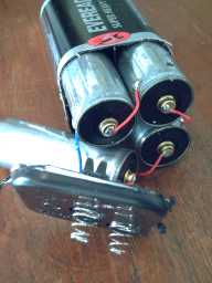
Better Connection?
The trouble with the graphite and carbon rods seems to be
contact resistance rather than internal resistance. I made some
"ligatures"
to clamp all the way around the carbon electrodes, which would surely
contact at several points. The dry cell makers crimp a piece of metal,
the "+ button" over the carbon rod - the origin of having a button at
the "+" end of the cell - but I don't have such a crimping
tool. So far the ligatures haven't solved the low conductivity problems
- but at least you can solder a wire to them!
Perhaps one way to approach the problem would be to line
the outer face of the graphite sheets with plasticized graphite that
wouldn't let electrolyte through. Then a wire mesh could be placed
behind in the dry area, in contact with the plastic all over (which is
in contact with the graphite all over), and soldered to a metal
terminal.
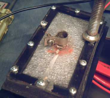 Nickel-brass ligature clamp to get best connection from carbon rod
electrode terminal
Nickel-brass ligature clamp to get best connection from carbon rod
electrode terminal
(The foam plastic was put in to push the electrodes together.)
Best Case Scenario?
With all the battery cases I've made that have leaked
under
pressure, I keep wanting something like a tub with straight sides -
just like people make for battery cases, but not to sell in stores. On
the 24th I thought of ABS pipe again, and how a flat end plate on a
piece of pipe could
leak, but how much plastic and weight a regular end cap on a pipe has.
Then I thought, "What about just the end cap itself?" A flat end cap is
a round tub
with straight sides, and it's 1/2" bigger inside diameter than the
pipes. I zipped off to Rona and bought one for 4" pipe to inspect. It's
a little
shallow (47mm) for a 6-cell, 12 volt battery, but good for 6 volts (3
cells), at least. 6 cells could work with thinner electrodes. I worked
out
that the 4.5" I.D. gave 16 square inches of electrode surface, just a
little smaller than my planned 3" x 6" rectangle size, and the volume
of 13 D cells - almost half a litre.
The next day I went to Bartle & Gibson for a cast pipe
coupling for the Electric Weel motor, and since I was there I also
picked up a
6" pipe endcap.
That size gives 34
square inches and a volume of 1-3/4 litres. That would make fantastic
batteries, but somehow I can't see making electrodes that big.
Especially compacting them.
Only the top will have a seam to leak, and the two
electrode terminals will of course have holes. Being round, the seam
will be uniform and won't tend to bend out under pressure like the
middle of a rectangular side. That's about the least amount of
potential trouble it's possible to have. The top could be both glued
and screwed on. Or, a recessed top could have a ring of 4" pipe glued
over it to help seal it.
Of course, a round electrode compactor of the right size
will be required - another tool to make. And round will be somewhat
wasteful of graphite sheets. The shape would at least be amenable to
use with a 45 ton(?) hydraulic press for faster
production than my bolt-down-edges type compactor. But I'll have to
stick with the 1.5"
x 3" rectangle test size until and unless I get to the point of having
practical, working batteries.
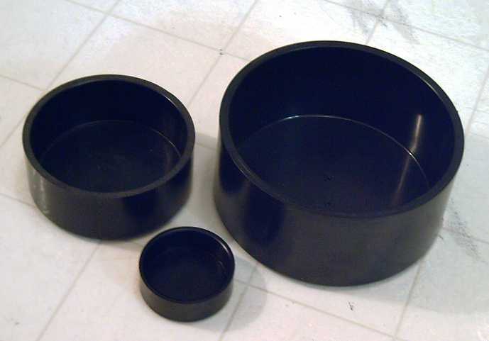 2", 4" and 6" ABS drain pipe end caps.
The 4" might make nice EV batteries.
The 6" is probably just a pipe dream - it would take a tremendous press
to compact such huge electrodes,
and they would be hard to install intact unless I can make them much
stronger or more pliable.
http://www.TurquoiseEnergy.com
Victoria BC