Turquoise
Energy Ltd. News #38
Victoria BC
Copyright 2010 Craig Carmichael - April 2nd 2011
http://www.TurquoiseEnergy.com
= http://www.ElectricHubcap.com
= http://www.ElectricWeel.com
Feature: Electric Hubcap Motor Making Kits:
$499.99
(no where near $500) - Taking orders now.
Month In Brief
(summary)
* Plus opinion... Natural resources: public property?
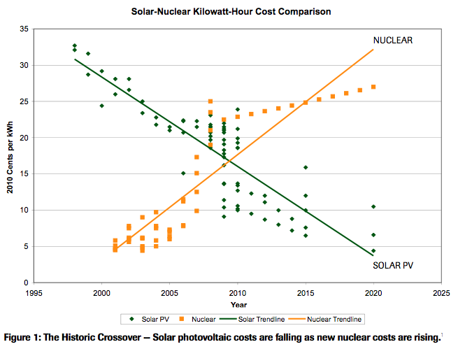
* Plus news item... The End of nuclear
power? A study says that in an ongoing trend, the cost per KWH of
electricity from solar panels has dropped
below that for nuclear plants. (It crossed over in 2010 for new
construction... and that's before Japan!)
Electric Hubcap System & Motor Building
Workshops
* PP-Epoxy Stator Ring Mold - for stator production
* PP-Epoxy Stator/'End Bell' Rings: Same stator for any
configuration of
motor.
* Bearing holders, 1" rod axles
* INSOLUBLE Sodium Silicate coil coating
* "Regular Motor" configuration motor made, CNC setups...
* Ilmenite seems to work even better than ceramic rutile -
even lower motor currents!
* Flat steel rotor disks - cut by abrasive waterjet (it's much
cheaper than I expected). Motor only 4" long.
Electric Weel Motor Project (Electric Wheel
Motor... Rim Motor...)
* Flat plate rotor cut by abrasive waterjet
* more pieces to be cut, taper lock bushing
Torque Converter Project
Sigh, no time!
* Moving escapement pivots from inside the drum to outside: 6"
torque radius instead of 5".
NiMH Dry
Cell
Car
Battery Project - Get
the lead out - of
your car! Reduce vehicle weight! Reduce Fuel Consumption! Green
batteries! from $300. (e-mail me!)
* AA cells arrive, assembled new car battery - sure enough, 9
pounds instead of 12
Turquoise
Battery Project
* Tests: runs for days with 61 ohm load, but at pathetic ever
dropping
voltages - mostly under 1 volt.
* Repeated tests show similar performance: it's rechargeable.
* Improved case: thicker walls, better(?) '+' terminal
connections.
Newsletters
Index/Highlights:
http://www.TurquoiseEnergy.com/TENewslettersIndex.html
Construction Manuals and information:
-
Electric Hubcap Motor
- Turquoise Motor Controller
- 36 Volt Electric
Fan-Heater
- Nanocrystalline
reflective rear electrodes to enhance DSSC Solar
Cells
- Simple Spot Welder
for battery
tabs, connections
Products:
- Electric
Hubcap Motor Kits, Parts - Build your own ultra-efficient 5 KW
motor!
- Sodium Sulfate
4x
longevity additive & "worn
out" battery renewal.
- NiMH Dry Cell Car
Batteries (please e-mail me for batteries)
- NiMH Custom Batteries (EVs, E-Bikes, Scooters, etc. - no extra
charge)
- NiMH individual Dry Cells (D, AA)
are all at: http://www.TurquoiseEnergy.com/
Electric Hubcap Motor Making Kits
499.99 $Canadian - Electric Hubcap Motor Kit
Although I don't have
complete car installation systems yet, I think some people have been
waiting for the motors alone as they can have many uses. The last
details are finally falling into place as described in the Electric
Hubcap topic below, so I think it's finally time to start taking orders
for them as kits, with the caveats that it may be a few weeks before
they are actually shipped, that specs are only roughly determined, and
that the kits may be just a little "rough around the edges". (I will of
course try to minimize unwanted 'features'.) A $100 deposit will put
you
first/next on the delivery list.
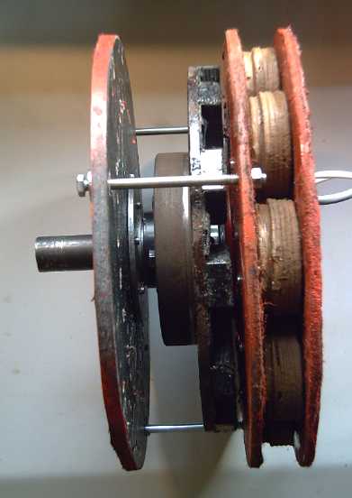
 Electric Hubcap kit configuration, Open edge view and closed.
(The disk brake rotor shown is being replaced with a flat plate rotor,
with the main body of the motor just 4" across instead of 5".)
The kits include all the parts to make one Electric Hubcap
Motor except they EXCLUDE:
* the 12 supermagnets (about 2" x 1" x .5" or 50mm x 25mm x 12.5mm)
Purchasers must buy their supermagnets separately - I can't supply them
for the sort of prices they're available at off web sources since
that's where I buy them.
* Epoxy resin. The magnets are glued to the rotor with a small amount
of epoxy resin, and then pieces of polypropylene strapping (supplied)
are glued over them to ensure they don't come loose. Although a cup of
resin is plenty, it's locally available everywhere and I think liquid
would complicate requirements for shipping.
* Brushless Motor Controller. That's a separate item. Unfortunately
mine aren't ready to sell yet.
* Mechanical Torque Converter to hook them directly to car wheels. I
don't have this working yet.
What the kit DOES INCLUDE:
6" x 1" 4110 HT SR machine shaft axle
SDS 1" Bushing (holds rotor to axle)
2 - 1" trailer bearings
2 - 1" trailer bearing races
10" diameter x 5/16" mild steel flat plate magnet rotor (without
magnets)
1 meter of 2" wide polypropylene strapping
Rotor compartment PP-epoxy cover bell (or end plate and ring for walls
- a last pesky detail)
2 - sets of bearing holder parts
9 - pre-made stator coils for 36 volt operation, with:
* low loss iron powder toroid cores
* ilmenite coating to improve magnetics and reduce losses (I
don't think any other motor has this!)
Inner stator plate/rotor-stator compartment separator
Outer stator plate
Magnet sensor PCB with 3 hall sensors with 5 pin flat rubber trailer
lights plug for motor controller connections.
APP connectors (70 amp size) for coil connections to motor controller
Angle iron 'feet'/mountings.
Stator vent cover screen
Miscellaneous nuts, bolts, washers.
Some Electric Hubcap Motor rough specs
approx. 12" diameter x 4" body length, rotor 10" diameter, center of
force: 4" radius.
Brushless, 3 phase, axial flux, 120º Hall effect magnetic polarity
switches, air cooled.
5 KW, 36-42 volts (nominal), 0-127 amps. (12-14 volts, 0-380 amps with
parallel wired coils.)
Stator coils (9 of) to rotor supermagnets (12 magnets 2" x 1" x .5", 6
poles) flux gap: 14-18mm / .55"-.7".
Torque and speed vary with flux gap: "adjustable specs" motor. (Nominal
0-2000 RPM; .17 N-m/amp torque constant @ .65" flux gap)
Efficiency: around 95% peak, around 75% at max rated load (these are
both excellent figures)
March in Brief
I put off filling out Revenue Canada SR & ED project
forms, corporate income tax and my Personal income tax until March
20th, then spent many hours on them. (The last item remains to be
finished.) Until the 20th, work on the motors took first place.
At about the start
of the year, a friend took it upon himself to start rebuilding my
rather
primitively formatted website and give it some pizazz, which he had
been threatening to do for some time. He's a great
database and web design programmer. This project started bearing fruit
in
March, and TurquoiseEnergy.com
is getting a new and more professional look. At the same time, the work
has led to
me revise some obsolete info. But so far I haven't been able to pay the
web site revisions the attention they deserve.
Paperwork and web site
aside, the next thing to do was to get set up
for making all the special parts of the Electric Hubcap motors, so I
can offer them as kits.
I made a
polypropylene-epoxy composite
'stator ring' using the plywood mold. It was
gooey
and frustrating work. But if you're trying to do the best motors, they
might as well be
made of the best materials. I made a better, deeper mold with 'butcher
block' HDPE rings that would allow a simpler technique: pile in
shredded fabric, pour in epoxy, put the top on and press it down with
C-clamps. The molds themselves can also be produced and sold. In spite
of that, since the coil making has been much simplified, these 'rings'
are now the most labour intensive part of making a motor.
The new rings are 'universal': a stator made with them can
be used for any configuration of motor. They can bolt onto a trailer
wheel
hub or an axle flange, or hold a bearing race plate or a hub. The rings
can be on both sides of the stator coils, and they can form both 'end
bells' of
the motor. They can be made thick or thin by varying the amount of PP
material and epoxy used.
I decided to offer a 'regular motor' configuration kit,
with
the rotor and stator enclosed in a shell with a bearing at each end and
the axle sticking out one end (or both ends). That meant creating some
small metal plates to hold bearing races at the center of the rings.
Very large washers (4" OD) with CNC drilled bolt holes, one turned to
the bearing race size, turned out to be ideal to clamp onto the plates.
With those parts
done, only
revised tiny printed circuit boards for the magnet sensors and
miscellaneous bits remained. Perhaps I should get a small CNC machine
suitable for PCBs. I haven't made any myself since the cave days with
film,
photoresist and ferric chloride etching fluid, but APC charges just as
much for these simple , almost trivial, boards as for complex ones. On
the last night of the month, I roughed out the board layout.
The new motor had ilmenite coated coils instead of rutile,
and the no-load power drain seemed even lower. I mentioned the motor on
a list. Among several, I got a response from the owner of
SuperMagnetMan.com, who is
involved with the magnet end and has helped
design a fine motor himself.
Among other things, he said: "I am excited to hear about
your advances in this area. [snip] I have worked with lots of people
through this group and other places that are looking for something
similar to what you seem to have operating." And: "I have been wanting
this kind of motor for vehicles for the last 10 years [snip]."
I think customers for motor kits are out there if I can
(a) find them, (b) deliver what's needed (c) with decent quality and
service, and (d) at an affordable price. And doubtless there's some
DIYers who'll make their own, maybe buying some of the parts here -
hopefully after I get around to updating the (now pretty obsolete)
instruction manual, and maybe coming for a workshop to ensure they have
the finer details right (and maybe install the motor in its intended
application).
When the AA cells arrived I did a lighter car battery
- 9 pounds, still 30 amp-hours. It started the car, but it wasn't
as strong as the D cell battery (12 pounds) and I switched back after a
day or two.
But with the high energy storage per weight, NiMH AA cells should make
excellent electric
car/PHEV batteries.
For a week or more, most of the work was nice in that it
required little creative thought - just plug away at it. But there
seemed little excuse or reason to stop between morning and midnight,
and the desire to finish things - especially the motor in its new form
- was strong. Those hours can't be good
for
anybody, and everything else falls behind.
For my own MnMn batteries, I made a new battery cell case
with
thicker sides that I
hoped wouldn't leak. But I didn't get around to filling it. I ran some
long tests on the present cell which
showed that although self discharge is awful and the discharge voltages
and maximum current are pathetic, it will put
out small levels of current for days, and do so again and again upon
recharging, with even slight improvements at times: it has the essence
of a rechargeable battery. A light doping of osmium that probably
didn't contain much osmium on the separator sheet made a minor
improvement. I'll try to ensure more of it gets employed in the next
cell, which will also use salvaged dry cell MnO2 instead of cheap
(impure?) pottery supply MnO2. That might reduce self-discharge.
Opinions: Dropping Solar Power Prices - Natural Resources are a
Public Trust
It seems two people
once entered a nuclear
plant in Ontario to test security, and found that they could easily
have walked out with all the 'spent' nuclear material they could carry
to make dirty bombs or whatever.
Ontario Hydro denied that there had ever been a security breach and
said everything was perfectly secure. The nuclear industry puts much
pressure on politicians and governments to adopt nuclear power plants,
with the same bland assurances that everything is perfectly safe and
nothing could happen, and that the country can't do without nuclear
power.
The USA has hollowed out a whole mountain to store nuclear
waste in. It will need to be
guarded for longer than recorded history at taxpayers' expense. A large
area around Chernobyl including the town is uninhabitable and will
remain that way for a long, long time.
The worst potential
radiation effects - probably alarmist, but who knows? - of the nuclear
plant disasters resulting from
the Japanese earthquake and tsunami appear to be (a) the loss of
mountainous Japan's main agricultural land area, (b) the end of many
Japanese cities including Tokyo, and (c) the end of fishing in affected
areas of the
Pacific. And at times, the Pacific coast of North America is directly
downwind of the dying Japanese reactors via the jet stream. The
Canadian government - before it could possibly have had time to check
out the facts
- quickly assured us there is nothing to worry about and that we should
take no
prudent advance measures, however simple, in case radiation hits us
here.
In case these lessons aren't abundantly clear on their
own, there's now a new reason to phase out nuclear power generation,
and never to build another new station:
The cost of photovoltaic solar panels has gradually but
continually dropped ever since they were first invented, while
the cost of nuclear power continues to rise. In 2010 a milestone
was reached: a report says it is now less costly to build installations
that generate electricity
from solar cells than from nuclear energy. The report may not be
entirely unbiased (any more than pro-nuclear reports), but the ongoing
trend seems clear. Perhaps it is solar electricity that will one day be
"too cheap to meter" - a one-time boast of nuclear power exponents.
(...and all this before Japan, and without my
nanocrystalline borosilicate reflective glaze for DSSC solar cells!)
---
Someone said they had heard on TV that among the 1% top
income 'earners' who now rake in 1/4 or 1/3 of America's wealth each
year are those who feel more at home with Saudi princes than with
citizens of their
own country. It can well be imagined that some of these people would
feel uncomfortable
around the citizens of the civilization they're pillaging, and even be
ashamed look them in the eye. The words
of the song One Tin Soldier come to mind:
Go ahead and hate your neighbor!
Go ahead and cheat a friend!
May they wake up and
see how shallow and unfulfilling is the obsession with wealth for its
own sake, and how destructive it is to their own personality and sense
of self worth when it's knowingly and willfully gained by manipulating
and exploiting others. "The love of riches all too often obscures and
even destroys the spiritual vision. Fail not to recognize the danger of
wealth's becoming, not your servant, but your master." - Jesus
---
Other than the need
for patent reform and for the missing government
Department of Progress, one outstanding societal structural flaw
promoting gross inequity would
seem to be the permitting of private ownership of natural resources,
such as oil, before they are extracted and processed. I believe the
principle needs to be established and made sacred that natural
resources are public property, to be under the control of a public
trust
or perhaps (in Canada) a crown corporation.
Private contracting
corporations may extract
resources from the ground and process them as called for by the trust,
but they will not own them. The
trust will sell the end products without discrimination to whoever
needs them, and of course some products like oil and gold can help the
government fund services with less taxation. This rather obvious step
should eliminate some of the unaccountable vested interests and their
obscene wealth, and their oppressive economic power to prevent progress
and keep civilization static and stagnant.
Electric Hubcap Motor System
Polypropylene-Epoxy Stator
Rings
I made another
stator with the plywood stator mold, this one as a flat ring to which
would attach to some sort of metal center. It was frustrating and gooey
work.
One change was that instead of
cutting 30+ circles of polypropylene, I took some of the scrap pieces,
and I took some bigger pieces, of both the nonwoven mat and the cloth,
and cut and ripped them into smaller
pieces. This was intended to eliminate the tedious cutting, and to
mingle the layers so it couldn't delaminate, as I had to a small extent
experienced earlier. Only a top and a bottom circle were cut. But in a
sense this was like starting all over again. I had no idea how much
cloth or how much epoxy would be needed, and there was no way to get a
good estimate except to see what came out of the mold.
I used 150 grams of epoxy on the first try, and I
neglected to weigh the cloth. The proportions seemed good, but the
piece was only 1/8" thick. Next there was just 150g of that epoxy left,
so I did it again. This time I used 72g of fabric. This ended up still
under 1/4" thick. Proportion was okay - it might have used a little
more cloth. Then I used around 235 grams of new epoxy and "some" more
fabric. It came out the desired 3/8" or so.
I had a problem weighing the epoxy as the digital
scale turned itself off twice while I was pouring it slowly in. (I also
went
months before figuring out how to turn this same scale off manually:
you have to hold the "On/Off" button down for about 3 whole seconds.
Another poorly designed product: the hardware is fine but the software
sucks!)
Anyway! It seems it took about 400-450 grams of epoxy and
200-250 grams of shredded fabric.
 Old ring mold (not a fungus)
The next day (6th), I made a second ring. For this one I used
360 grams of epoxy and 120 grams of PP fabric, and it came out just
under 1/4" thick, and seemed to have good proportions.
It was still gooey and frustrating work. One problem was
that the fabric wouldn't lie down and kept coming out of the shallow
mold while I was trying to put it in. Then, in spite of waxing them,
the epoxy stuck to the plywood
and to the wooden center I made. I decided to make a new mold out of
1/2" high density polyethylene 'butcher block', that the epoxy wouldn't
stick to. I spent the afternoon of the 5th at my brother's near
Industrial Plastics, waiting for them to cut my piece of HDPE.
There was no way I was going to try cutting these somewhat
pricey pieces by hand. I had just learned the programming and technique
for routing
curves and circles with the CNC drill/router, so that was the obvious
way to go. I cut a 6" length of 300 mm PVC pipe (same as for the
motor bodies) for the outside edge of the mold, to solve the
fabric flopping out problem. Instead of brushing on the resin to wet
down the fabric and
get it flat enough to work with, I'd simply throw in fabric and pour
in resin, then cram the top ring on it and clamp it down with C-clamps.
Then I realized I'd need gigantic C-clamps to fit over the
6" sides. I trimmed the pipe down to 4-1/2", and bought 3 more 4"
C-clamps that would fit over that. The mold had now cost $60 and
several hours work, exclusive of an unexpected $40 and more time to fix
my air compressor, which the CNC machine needs to raise and lower the
tool.
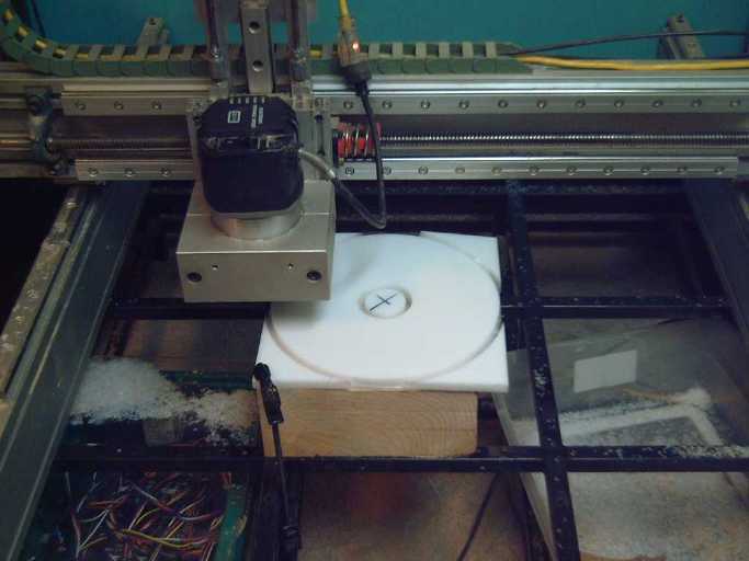 CNC machine with router, cutting HDPE stator mold piece
The final piece was a 2.75"
OD center pipe. A 4" piece of aluminum pipe 2.85" OD was found and
given to me at Smith Bros. That at least didn't cost a lot, but I spent
a couple of hours on the lathe shrinking it to 2.77". (partly because
my cutting tool was dull - it really helped when I finally
thought to try another one.)
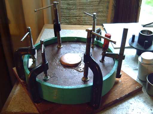
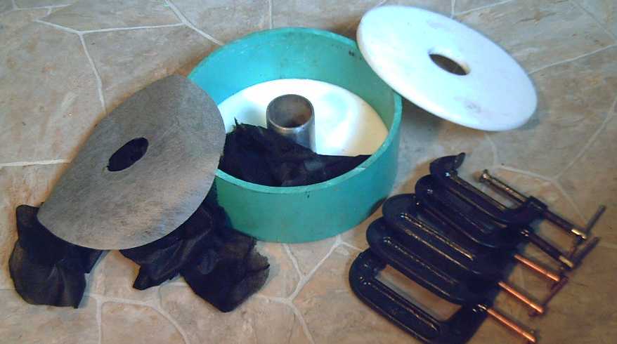 New ring mold
Drop in bottom mat (left), then some shredded pieces of fabric, some
epoxy and repeat, then place top mat,
top mold ring over that, and compact it down with C-clamps.
The first ring I made with this new mold had 150 g of
fabric, 450(?) g of epoxy, and came out 1/4" thick and was a little dry
in
spots. The next one used 150 g of fabric, 510 g of epoxy, and took 45
minutes from start to putting it in the oven - a bit laborious, but
much less so than previously.
That seemed fine, but when I took it out, it had large dry
sections at the outer edges and it was .33" thick on one side to .42"
opposite. Since I used no more cloth and more epoxy yet had bigger dry
areas, it would seem one must pay very close attention to distribution
when piling in the fabric, distribution when pouring in the epoxy, and
the tightness of the C-clamps, which I had done up less tightly this
time, fearing I might be bending the plastic mold pieces.
I'm getting better at this, but I think the real answer is
to find still more improvements to the technique.
I calculated co-ordinates for the coil mounting bolts and
some others - lots of sines and cosines on a calculator - entered them
into a CNC drilling program, and made two PP-epoxy rings into a stator
and one into an end bell for the other end of the motor. Some other
holes I drilled by hand and will add to the CNC program later, and
differentiate between the inner ring, outer ring, and end bell pieces.
When this is all ready and programmed into the CNC machine
I can sell not only finished rings, I can sell the
CNC-made molds - and manual drill guide templates - to help others do
more of their own
making of
motors as well. This is part of the counter-intuitive business
strategy: If this catches on, there are
250 million vehicles in North America almost desperately needing
electric propulsion. The more molds, etc, that I can produce, the
faster it'll spread, and it will take many years to saturate the market
no matter how many people start making them. To paraphrase a famous
saying, sell someone a motor and you have one electric car - sell them
means to make motors, and they'll grow a whole crop of them.
Or perhaps some sort of franchise system could be worked
out.
Metal Ring Centers - bearing race holders
Next, what goes in the hole in the middle of the ring? For
motors with a bearing at each end, I had been trying
to come up with some sort of plate. I went out and bought some huge
washers, and ended up using two that were 4" outside diameter, bolted
together and sandwiching the plastic ring between them. The center of
one was turned on the lathe to fit the bearing race, while the other
prevented the race from pushing right through.
Next I set up the CNC to drill 5 holes
in the washers for 5 bolts to hold them together. Using the machine is
the only way the holes will all line up properly, and they can be
cranked out easily when and as required.
For the thicker
rings, center washer spacers
that fit are
necessary to prevent the race from falling in between the big outer
washers. Unfortunately the best spacers I've found still require work -
grinding 5 indents where the bolts go through to accommodate them, as
the outer diameter is just a bit large on the size where the inner
diameter
is good.
The Form of the Motors -
"ordinary motor" type
I got a trailer hub - the new stator ring would bolt right
onto it. Then I started thinking about shapes and forms. My axial flux
motors have both bearings at the stator, whereas most motors have one
at each end of the body - one on each side of the rotor.
Mine can exist and run without having a body
over the working parts, which, as I stop to think about it, is rather
unusual.
But whatever form is best for a motor with a torque
converter, for an ordinary motor that spins a shaft, the shaft will be
stiffest with bearings at opposite ends. I'm going to use
the new 'stator rings' also as 'end bells', with the turquoise PVC tube
for
the bodies as originally planned.
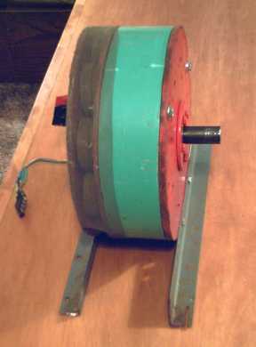
 Electric Hubcap in an enclosed "ordinary motor" guise.
This was a first "mock-up". Then I asked myself why it needed two
layers of outer case over the rotor, and eliminated the outer one.
This will be one more of several unique EH
rotor-stator-axle-bearing configurations that may be adopted for
various purposes - one of general utility and familiar to most motor
users. By making the
stators as flat rings, one standard design of rotor and one of stator
can now be employed to form any of the configurations.
Axles: 1" Steel Rod Shaft
I couldn't fit the rotor and stator properly onto a
trailer axle. But after trying the encased motor layout, I realized
that an
axle end nut wasn't needed, and that the optimum axle for it would be a
simple 1" hard steel shaft such as "drill rod", which could be cut to
any desired length, with the "SDS" taper lock bushing to hold
the magnet rotor and provide a base for the bearings. At Metal
Supermarkets I got a hard steel rod
called "heat treated, stress relieved, 4140 machine shaft", which
sounded like the best and was also (unlike drill rod) economical. It
only
needed to be 6" long, with the bearings at 0" and 4" leaving a 2"
projection. Such a short axle is inherently very hard to bend, so I'm
confident the strength is more than adequate.
Once I had this piece along with the others I'd made or
gathered, the steps for putting together a motor fell into place.
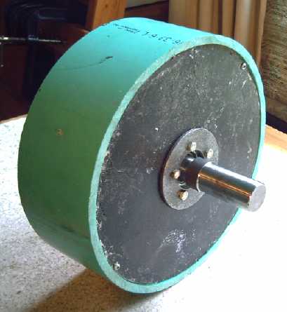
The new motor without the rotor cover
The stator and the rotor form two separate compartments
Cooling air flows by the coils from the rim to the interior, through
holes to the center of the rotor,
is flung outwards by the rotor magnets ("fan blades"), and exits
through holes in the left hand cover.
All assembled
March 28th: I had a steel flat plate rotor made by abrasive waterjet
cutting.
I re-assembled the motor with it to check the fit. The motor body is
just 4" long (or is it 4" thick?),
The rotor cover will be just over two inches across.
The thickness of the SDS bushing that clamps the rotor to the shaft
prevents a further 3/4" reduction.
The main thing left to do before I can sell these motors
as kits is a revised circuit board for the magnet sensors, and I layed
it out on the night of March 31st. I would also like to change the
shaft
end bell to a one-piece bowl shape with integral sides. This will
better ensure proper alignment, and also that the motor can't be run
without the protective cover over the rotor the way it's seen in a
couple of pictures here.
I think I'll also sell the kit sans supermagnets. I don't
do anything with them here, and I would just have to import them, and
then in many cases re-export them, all at extra expense in taxes, fees
and shipping. People will can just as well order their own. It lets me
knock off around 125$ from the kit price for around 75$ in magnets. The
price of the complete motor kit (without magnets) will
be about 500$.
INSOLUBLE Rutile (Titanium
Dioxide)/Sodium Silicate Coil Coating
The rutile in sodium silicate coating on the coils
definitely improves the
efficiency of the motors. But the water soluble sodium silicate medium
seemed to portend poor durability of the coating.
In trying to figure out ways to make the rutile/sodium
silicate coil
coating insoluble, I had been forgetting one of sodium silicate's most
interesting properties - when heated to 99-105ºC, it loses its
water of hydration... and thereupon becomes insoluble, all by itself.
Problem solved! The coating doesn't look any different, but it no
longer will dissolve in water.
The wire insulation and the epoxy are rated for about
200ºC, but it does mean taking the coil cores above their
70ºC rated temperature for a few minutes to do it. The
manufacturer says that's no problem - the coils degrade, but slowly
over time, if
they're
too hot. A once-only overtemperature is thus different from having it
as a continuing or repeating condition while running the motor.
The other problem, the coating flaking off, is a bit more
tricky. Painting on a stiffer mix (less water) seems to help, but it
really doesn't bond to the cores. Perhaps I should rough them up with
sandpaper?
The other experiment, painting on 2 or 3 coats to see if a
thicker layer helps even more than thinner, also remains to be tried.
Ilmenite...
As a further experiment, on the coils for the next motor
(seen above) I
tried using ilmenite, a mineral blend of titanium and iron. (FeTiO3).
The TiO2 alone (rutile) is much better than air, but perhaps the mix of
nano-size
paramagnetic and ferromagnetic attributes would create a still better
magnetic path from the outside of the wires into the core.
Ilmenite responds weakly to a magnet, suggesting (along with the oxygen
content) that the iron is in more of a ferrous (FeO) valence state than
ferric (Fe2O3).
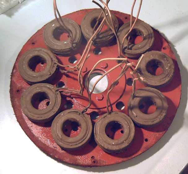 The ilmenited coils on the new (painted) stator ring. The
center hole holds a bearing race.
The ilmenited coils on the new (painted) stator ring. The
center hole holds a bearing race.
The rotor magnets, acting as a fan, will be right behind this
ring. Another ring will enclose the coils,
and the vent holes will pull cooling air in from the stator outside
edge,
across and through the coils.
That ilmenite might well work even better than rutile was suspected...
just look at that
rich,
creamy chocolate color! (doubtless supplied by the iron content.)
When the new motor was
finished on the 19th,
I measured the no-load currents. The gap was about .6", and the
coils are 20 turns of old cotton insulated #11 wire (3 phases with 3
coils in series) whereas the previous motor is 61 turns of #14 (3 of 3
in parallel), and the flux gaps were different. In addition, the
bearing setup is a bit different with one bearing now on each side of
the rotor. So some difference in
figures may have other
causes than ilmenite versus rutile.
I'm not making enough motors (so far) to try out just one
small change per motor as they've so rapidly evolved.
Interpolating last month's rutiled coil results for a .6"
gap estimates
38 watts at 500 RPM and 105 watts at 1000. The new motor, with the
ilmenited coils (and the comparison-disruptive factors mentioned),
produced the
table below. Power was two NiMH dry cell batteries providing about 26
volts. Results compare favourably with the previous, at 31 and 88
watts, a further 15-20% idle power reduction.
RPM
|
Current (Amps)
|
Watts (A * 26 volts)
|
500
|
1.2
|
31
|
1000
|
3.4
|
88
|
1500
|
5.4
|
140
|
The coils felt cold after the tests,
but the 1/4" x 2" coil mounting bolts (at least, their heads) were
noticeably warm. Zounds! Perhaps I should use thinner or
non-metal bolts, too! I think I'll try #10's next time. With the double
ring stator, they should be stiff enough.
Iron Powder Cores Info
I called Micrometals and found out that (a) the iron
powder size is on the order of 100 microns, and (b) that it is
pre-coated before making it into cores so that the particles don't
short into one big iron conductor, with all the nasty eddy currents
that would result in.
I should think that
having nano-size iron particles would be theoretically optimum, though
improvement on
near perfection may be a bit academic. Problems with producing iron
nano particle cores would be: (a) getting iron particles so small. It's
easier to get 'nano' with oxides, but iron metal is best. (b) coating
such tiny particles to insulate them. And even if they were coated, it
would have to be a nano-thin coating as well or it would be mostly
inert coating with little actual iron.
The glassy ceramic substrate I was trying to do with
ferrous
(FeO) and paramagnetic TiO2 particles might work (if successfully made
- in a reducing atmosphere kiln), but I'm not confident it would be
better - it would be better than air, and almost 100% lossless, but one
might need substantially more core to do the same job, meaning a bigger
motor for the same power.
The Electric Weel Project:
The Car Motor of the
Future?
I decided this giant diameter motor should have a solid
steel plate for the
rotor after all - if only a thin base. I'd hate so much to have a weld
give way and see a
huge spinning rotor fly to pieces! I thought I could really use that
pulsejet steel plate cutter that I didn't finish making last fall -
cutting out a 26" round steel disk with the angle grinder has very
little appeal.
Instead, I called Waterforce abrasive waterjet cutting in
Sydney, and found the price for cutting such disks is much less than I
feared. So I asked for a 26" disk of 1/8" mild steel.
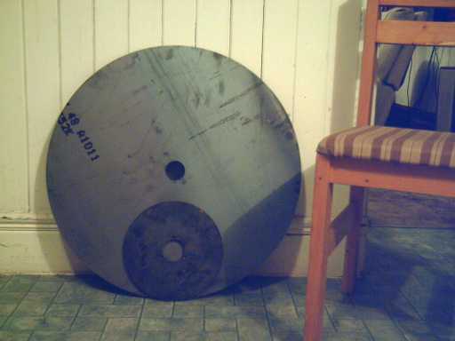
26" diameter rotor disk of 1/8" steel (20 pounds)
with 10" EH disk and chair for comparison.
Next (latest plan), I'm
having a 26" steel ring cut 2.125" wide from
3/16" stock. This will go around the rim as a stiffener, a thicker base
to mount the magnets on, and to carry the magnetic flux between
magnets. The inside piece left over from that ring is to be the
center of the stator, which needs to be non-metallic in the outer area
under the magnets. I hate to think of the mold it'll need and all the
epoxy it'll take to do the giant 'stator rings'!
And it occurs to me that with the SDS taper-lock bushing
attaching the 10" rotor to the 1" axle seeming to work so well, all
that's needed for the bigger motor is bigger SDS tackle. SDS bushings
for shaft sizes up to 2" are in fact available so I bought one.
When I have the steel pieces - and some time - I can
continue the project.
I still think the pulsejet steel cutter would be a cool
tool to have!
Mechanical Torque Converter (MTC) Project
I decided to change the torque elements, and to have three
curved 'strike' teeth 120º apart on the motor rotor, that would be
'hit' first at a very shallow angle, that gradually steepens so as to
operate quietly and produce a smooth pulse of torque. Then three
'escapement' arms to strike them, on the output drum.
Variants of two, three, five and six teeth and arms can be
tried
pretty easily. Near the end of the month, I realized I could put the
pivots on the outside of the drum and just have the points sticking in
- this would give the largest radius of force, about 6" instead of 5"
or 20% better torque from the same pulses.
I may also put springs on the escapements, causing one
hook to try to stay down. This isn't in accord with the oscillating
masses operating principle, but it could help transfer more force from
the motor to the output during each pulse.
I also looked at a truck this month at Canadian Electric
Vehicles, with an electric motor
driving a set of planetary gears whose output turned the drive shaft to
the rear differential. That motor must really rev up on the highway.
Speeds of single gear ratio electrics are evidently often limited to
about 80 Km/Hr.
The value of a torque converter is again brought home: to provide the
required torque at low speeds yet keep the motor revs down on the
highway - and to do it all with greater efficiency than the gears.
I hope I can find some time in April to work on it!
Ni-MH Dry Cell Car Battery Project
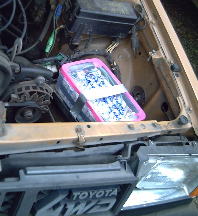 NiMH
dry cell battery #2 in a better fitting enclosure under the hood: 30
AH, 30 D
cells.
NiMH
dry cell battery #2 in a better fitting enclosure under the hood: 30
AH, 30 D
cells.
Starts great even at
-6ºC! Under 12 pounds - the
car is 30 pounds lighter!
(Strap is aluminum. ...though duct tape might work fine if you
can wrap it on somehow!)
Best Charging Voltage?: car
alternator's
13.8 volts not
only works: it's Ideal!
For a typical battery charger, charging up NiMH cells from
low to
full, voltages up to perhaps 1.41 or 1.42 volts may be used. Then the
charger
shuts off. In the car,
the battery usually doesn't get
discharged very far, and driving continues until a destination is
reached, not just until the battery is charged. But NiMH cells don't
stay up
at 1.4+ volts, they discharge to between around 1.37 and 1.33 in a few
hours or in a day or two - even lower after some days or weeks unless
they're the 'low self discharge' type. Let's call them 'overcharged' if
they're above that. If a cell keeps getting strongly charged for
extended
periods when it's already full, it may shorten the life, and anyway
it's doing no
good. My first in-car test showed that the car alternator's 13.8 volts
is
acceptable, but what really is the best constant voltage to
charge at if a battery is going to be left on charge for long
periods such as while driving?
I ran a test to find out. I charged one of my NiMH car
batteries (sets of
10 cells in series, so voltages are *10) with the lab power supply at
14.10 volts. The current gradually settled to about 4 amps and stopped
going lower.
I reduced it to 14.00 volts. Since the battery was charged
nearly to 14.10, the current stopped. But when checked a couple of
hours later, as the
'overcharge' reduced, the battery was again drawing abut two amps to
hold it at 14.0 volts.
I reduced it again to 13.95 volts. Again the battery
stopped drawing current for a time, but 3-4 hours later, it was up to
400 milliamps - much better, though still a higher trickle charge than
desirable (and a needless 5 watt power drain).
Then down to 13.90 volts. This time as the voltage dropped
the
current came up to only about 80 milliamps. Divided amongst 3 banks of
D cells (or 12 banks of AA cells), this is a very acceptable continuous
trickle charge current.
Next test was at 13.85 volts. It took longer for the cells
to drop from 13.90 to 13.85 since they were much closer to staying up
there by themselves. The current to keep them at 13.85 was trifling -
the current meter needle on the power supply barely moved.
Then down to 13.80 volts. It took longer for the cells to
drop down to the new voltage with each drop, and this one was took some
hours. I would have had to connect a milliamps meter to read the
trickle current.
It took overnight to drop from 13.80 to 13.75 volts. This
might mean it was a few percent below 'full charge', eg 97%. Not much
in the overall scheme of things!
It took about a day to drop from 13.75 to
13.70 (temperature around 12 to 15ºC), so considering typical
self-discharge rates, one suspects that could mean at 13.70 it's not
quite fully
charged, eg, it might sit at around 90-95%.
Conclusion: for a constant voltage charge of
indefinite duration, a good voltage to charge at is about 13.75 to
13.90. This will keep the battery 'topped up' to 100% without
overcharging it. By some fluke of chance, car alternators put out 13.8
volts as a standard, making NiMH batteries ideal car batteries. And
they are more ideal than lead-acid, because until they're considerably
discharged, they sit up over 13 volts, so headlights will hardly dim if
the engine is
off. This will be especially useful for a car running on
electricity
instead of gas.
Continuous
Charge
Voltage:
13.65 - too low, won't be well charged
13.70 - okay, might stay slightly undercharged, eg 90-95%
13.75 - good: virtually no trickle charge. If undercharged, it's only
by a very few percent
13.80 - good: trivial trickle charge (10mA?) <-
standard car alternator voltage!
13.85 - good: trivial trickle charge (20mA?)
13.90 - okay: draws an allowable trickle charge (eg, 80mA)
13.95 - okay but a bit high: a considerable trickle charge (eg, 400mA)
stays on
when battery is fully charged
14.00 - too high: keeps drawing a couple of amps when fully charged
On measuring, I've discovered that MY car's alternator is
putting out 13.95 volts. It may well be that on older cars, the voltage
is really regulated by the current, so it probably rises to give the
NiMH
battery the same current as it would give a lead-acid battery. It's
still workable. I expect that newer cars made in
the solid state era have better regulation.
Speaking of Chargers...
Okay, so how do you charge NiMH 12 volt batteries that
aren't connected to a car alternator? I found a good 6 or 2 amp charger
for $40 in the automotive department at Canadian Tire, model 11-1526-8.
It's said to be for lead-acid batteries, but inside are two trim pots
that can be adjusted. The one towards the rear changes the voltage at
which the green LED comes on saying it's charged and the current to the
battery shuts off. With the nearly charged battery connected, turn it
clockwise to reduce the shutoff voltage to about 14.1 to 14.15 or maybe
14.2. It takes about 20 seconds to react - not to mention you have to
wait until the battery charges to the right voltage - so patience is
required. (The other trim pot more towards the front seems to adjust
the 2 amp rate current setting.)
NiMH dry cells technical advances: Improving EV energy densities?
The first NiMH AA dry cells I bought in 1996 were an
impressive 1.6 amp-hours - over triple the last NiCd's I'd had. Today
2.3 to 2.6 is the norm. With 2.5
AH AA cells, GM's EV-1 could
have had about a 200 mile range instead of 100 miles, with the same
total weight of batteries.
I recently saw a
NiMH AA cell with some odd
brand name
claiming to
hold 2800mAH of charge. It weighed 27 grams, 10%
lighter than most. I couldn't take it and run tests on it, but
taking the specs at face value:
2.8 AH * 1.2 V / .027 Kg = 125 watt-hours per kilogram.
That's over 20%
higher than the previous best, and well up into the range of the high
density lithium ion types. It's also over double the energy of NiMH
flooded cells I've seen specs for such as those used in the GM EV-1.
These sound like
great EV
batteries. If 2.8 AH, 125 WH/Kg, is the coming standard, in the choice
between
lithium ion and NiMH, it may boil down to price, cycle life and
performance: which
is really better value? Here, eg, the 7 pound, 10 AH electric bicycle
L-ion pack at $1000 would have to last a very long time or come down a
long way in price to outdo a 7-1/2 pound, 11.2 AH $300 or even $400
NiMH
pack. And the NiMHs are inherently good performance, and
environmentally nontoxic at the end of their
long life.
The chemistry? One surmises
the positrode must have manganese in it,
charging to permanganate, or that much of the nickel charges to NiO2
[valence IV] - or both. Otherwise it's pushing the limits of the nickel
to an amazing
degree. The traditional nickel charge from Ni(OH)2 [II] to NiOOH [III]
is
theoretically only 289 AH/Kg, and it really only attains around 217. So
the weight of the Ni(OH)2 powder alone would have to be 13 grams - half
the total weight and probably 3/4 of the bulk, which doesn't seem to
leave enough for everything else.
The alloy of the hydride must be very good, too, one of
the best sort of 1000+ AH/Kg types. This is about the same in theory as
my Mn
negatrode, but at a lower voltage. The overall chemistry is obviously
getting very good.
If the positive is charging to MnO4 and probably NiO2
(both at almost the same voltage), it's the same 'mixed valence' Ni-Mn
system I'm using, except mine is in neutral (KCl salt) solution where
the reaction voltages are double what they are in alkali (KOH), and
I've added gas recombining catalysts to reduce pressure and chelating
agents. Except for the lower voltages (of both electrodes) and hence
lower energy
density, higher operating pressure preventing large cells, and the
higher materials costs, it would seem the latest NiMH
dry cells accomplish - in miniature - much of what I've been hoping for
from my own 2 volt
cells.
120 AA Cell Car Battery: Tenergy D
cells prove better than Tenergy AAs for starting cars
I got 200 AA cells, ordered in February. I used 120 to
make a 30 amp-hour car battery. This would theoretically operate the
same as the 30 D cells battery. But it weighed 9 pounds instead of 12,
each AA cell being less than less than 1/5th the weight of a D but
holding 1/4 as much energy.
AA: 100 WH/Kg (energy density by weight)
D: 75 WH/Kg.
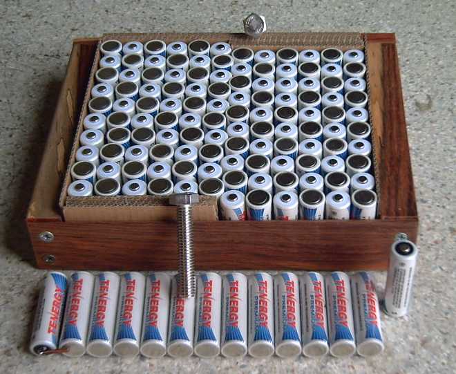 120 AA cells soldering jig
The skew at the center was to make room for terminal bolt heads in the
smallest possible case.
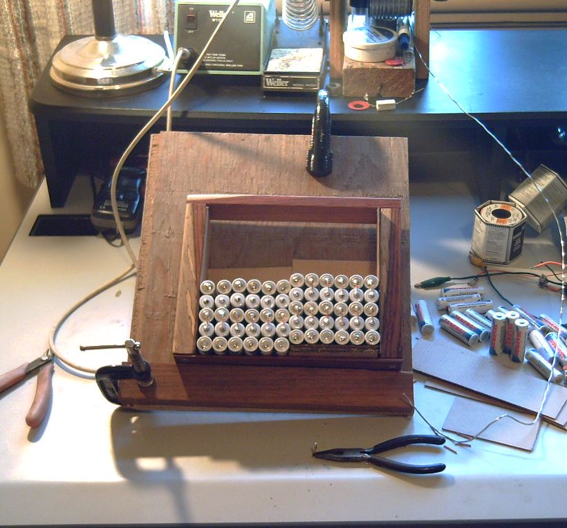
The cells kept getting out of place, falling over, etc, so I put the
jig on a slant.
Having now soldered together many hundreds of cells in my long
career without
ever having any resulting problem or battery trouble, I
suggest that no one who solders should hesitate to solder together
batteries from dry cells. I think reluctance to solder dry cells has
been a major unrecognized factor
holding back
utilization of the best small cells such as these for greater purposes.
As assembled, the 360 WH
battery weighed 4.00 Kg and was thus down to 90 WH/Kg. Using lighter
wire,
skimping on the solder, and having no enclosure are probably not the
best options. Smaller, lighter terminal bolts could shave off 40 or 50
grams - I've been using big 3/8" ones whose big washers can clamp down
car battery
cable
clamps, but that's unnecessary for EV use.
In operation however, the
AA battery delivered lower voltage supplying the 200 amps to the
starter motor. Voltages down to about 8.2 volts were caught on the DVM,
versus 9.3 volts and up with a D cell battery. And sometimes the car
hesitated to start although it was cranking over fine. Although it's
hard to get better than a rough
approximation of a very short duration minimum voltage with a simple
meter that
samples the voltage at a 'random' time, it would seem a D cell can put
out the same high current as 4 AA cells with 10-15% less voltage drop,
even though the amp-hours ratings add up to the same. Perhaps that
extra weight in the D cells goes into heavier internal conductors. (It
probably also needs a thicker case to hold the same pressures in a
bigger cylinder.) To
get the same performance as the 30 D cell battery, the AA would need
around 150 cells instead of 120, bringing the weight up to 11 pounds
(and the amp-hours to 37.5) and costing more. Of course, it's possible
this may apply only to "Tenergy" brand cells, which is the only brand
I've tried, and maybe even to these two specific models, so a
hard conclusion of "a D cell provides more current than four AAs" may
be premature.
With what I have though, I've decided that the D
cell battery is more practical for a regular car battery, and switched
my own car back. Three 'extra' pounds means little -- 12 pounds is
still 20 pounds lighter than lead-acid.
The situation is different for EVs and PHEVs, however. In
that case, enough cells are needed to provide a desired electric
driving range - say from around 2000 AA cells up. With so many
cells - and an efficient drive system - the current demanded of each
cell isn't so high. Instead, it is probably more important that the
2000 AA cells weigh 60 kilograms (132 pounds), versus 500 D cells at
81.5 Kg (180 p). Increasing from that minimum to 24 KWH to push the
driving
range up to perhaps 150-200 miles shows more significance: 530 pounds
for 8000 AAs is almost 200 pounds lighter than 720 for 2000 Ds.
Those new(?) 2.8 AH, 27 g AA cells would be only 193 Kg/425 pounds -
another 100 pounds off.
Versus Single-use Alkaline
On a list someone said he had discharge tested 4-packs of
single use alkaline batteries versus nickel-metal hydride. His graphs
show the NiMH to be superior in every way - and they can still be
discharged 999 more times, while the MnZn alkalines are spent.
The only value of the MnZn type is that the self discharge
is very low. It can be kept around for a long time without attention
until needed.
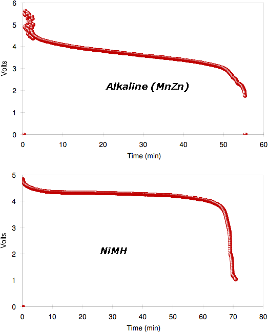
4 AA cell packs of same brand tested with 2 ohm load (note that the
voltage and time scales are unequal):
At this heavy load, one charge of the 2450 mAH NiMH battery ("5 volts")
outperforms the single use ("6 volts") alkaline battery's only charge,
not only in total run time but also in voltage and current output over
virtually the whole discharge period.
The Car Batteries for Sale
ad:
30 AH (210 amps cranking, small car) - $300
40 AH (280 amps cranking, mid size car) - $400
50 AH (350 amps cranking, V6?) - $500
60 AH (420 amps cranking, V8?) - $600
Custom EV, PHEV, cycle battery configurations (any voltage, current) -
$proportional, nothing
extra for being custom.
Individual NiMH cells:
10 amp-hour D cells: $10 each
2.5 amp-hour AA cells: $2.50 each
Turquoise Battery Project
Wasting Time Plugging Leaks
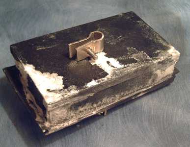 Salt encrusts leaky test battery
I decided it might be nice to try using 2" ABS pipe
endcaps for small test battery cells since my square glued together
ones nearly always seem to leak, and on the 4th I went to make an
electrode compactor for it. I couldn't get pipe and steel rod that
matched in diameter, so I had to make my own, turning plate steel into
round bits on the lathe.
I spent
some hours making it, getting everything just right - only to find when
I fetched
the ABS pipe cap that I'd made it all 1/4" too small - the pipe size
instead of the cap size. Back to the leaky
glued rectangles!
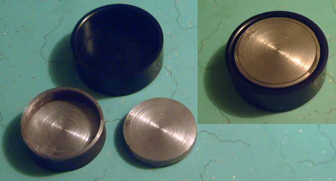 Wasting time making a compactor that doesn't fit!
It then occurred to me that
I had found some 3/8" thick
ABS sheet a few months ago. Before that, I thought the thickest
it came was 1/4". If
I used 3/8" thick for side walls, there was a much better chance of
getting cells that don't leak: more glue, less flex, wider gaskets.
Along the same lines, I had earlier tried making a
transparent
acrylic plastic cover for one cell, but immediately inside that goes
the graphite sheet or sponge rubber, blocking any view of the
internals. This time I made two of the sides of 3/8" acrylic, so that
two cross sections can be seen. This may not show much of visual
interest either, but there's more chance than with either end face!
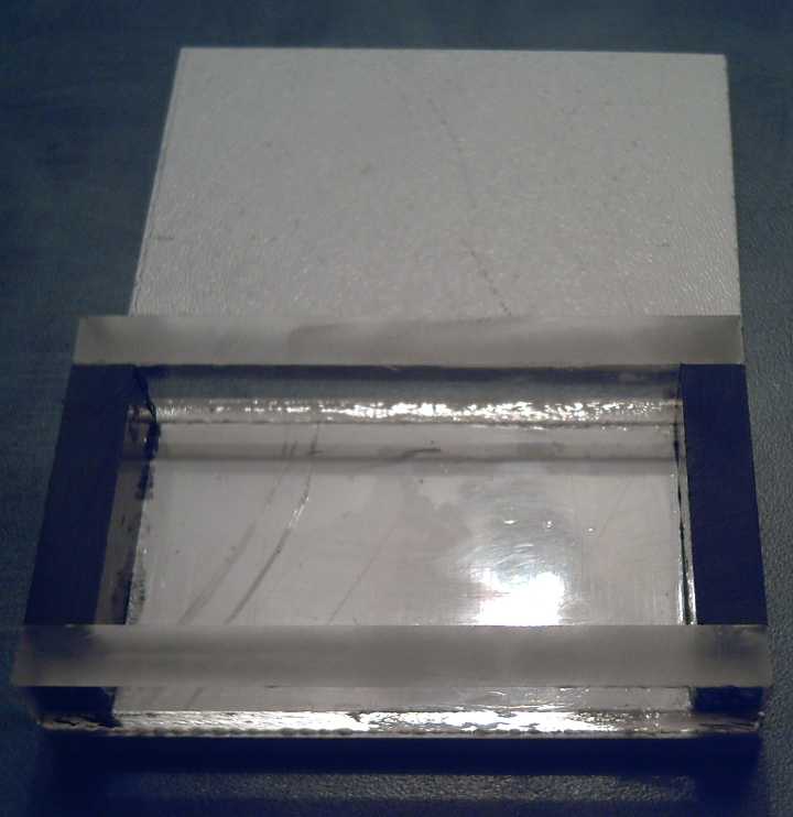 Thick walled battery cell case
white and black ABS, and clear acrylic sides.
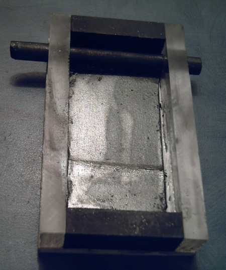 With graphite sheet and carbon rod with large contact area -- trying
to get lower resistance connections.
With graphite sheet and carbon rod with large contact area -- trying
to get lower resistance connections.
Osmium: a better dielectric?
I bought a gram of osmium powder well over a year ago now
as
a dopant for the separator sheet. It's over 100 $/gram and forms osmium
tetroxide, which evaporates as a poisonous vapour. I hadn't dared break
open the
container. Instead I've used ferric
oxide, but I think osmium will work better - with
luck a half an amp might become ten. Osmium is quite volatile, reacting
with air and water, and it is one of only three elements attaining a
valence of
plus eight, usually as osmium tetroxide. (The other two are ruthenium
and xenon - which is evidently less noble than the other noble gasses.)
Osmium will absorb protons and could be a good metal hydride if it
wasn't for the fact that it is so rare, and that it reacts with
alkali, the usual metal hydride battery electrolyte. Of course, I'm
using salt instead of alkali.
By its chart, it appears it could perhaps also make a
great positive electrode in spite of its high atomic weight,
potentially moving a whopping 8 electrons per reaction (at almost a
volt in acid... reacts with alkali... ??? for salt):

Of course, I just want it
as a dopant on a thin film in the separator. Near the end of March, I
finally opened the
tiny bottle and sprinkled a bit of the powder into a small test tube
with a few cc's of acetaldehyde. I hoped it was enough to have an
effect. A bit of this mix
I painted onto a piece of cellophane with a q-tip. (The rest went in
the fridge with a rubber stopper on it.) I took the battery I'd been
testing (leaky, above) apart and placed the new film next to the
positrode layer.
By using the same battery, changes of performance owing to the film
should be more
readily apparent than by starting fresh. It appeared to be a 15 or 20%
improvement, with slightly higher (but still pathetic) voltages and
currents - not the sort of "night and day" change I was hoping for. On
the other hand, it was a tiny fraction of a reservoir of acetaldehyde
with a fraction of a gram of osmium in it. Perhaps it wasn't enough.
Also, I shook it but didn't really stir it, and as I think about it,
the osmium (the densest element of all, at s.g. 22.6) may have mostly
settled to the bottom. The Q-tip only reached down to the top of the
liquid. Next test cell I'll sprinkle in some more osmium, and dip a
small paintbrush down to the bottom and stir.
I'll also use the MnO2 salvaged from the dry cells, as
that from the pottery supply may not be very pure - that could be part
of the high self-discharge problem.
http://www.TurquoiseEnergy.com
Victoria BC