Turquoise
Energy Ltd. News #40
Victoria BC
Copyright 2010 Craig Carmichael - June 2nd 2011
http://www.TurquoiseEnergy.com
= http://www.ElectricHubcap.com
= http://www.ElectricWeel.com
Spotlight: A new high energy, economical battery chemistry: 2.1 volt
V-Ni
salty cell.
Month In Brief
(summary)
* Most inventors are "unemployed"? Well, duh!
* Raising the bar - Mechanical torque converter - battery design
- Hubcap motor production
Electric Hubcap System
* A3938 V2 Motor Controller
* Motor Production Setup
Electric Weel Motor Project (Electric Wheel
Motor... Rim Motor...) (No activity or report.)
Planetary Gears Project
* Disappointing test in April leads to renewed thoughts about
dropping planetary gears, making a torque converter work.
Torque Converter Project
* oscillating planetary gear torque converter: rotary version of
Constantinesco's original design - an idea from chat list "half
bakery.com".
* My version of the planetary gear version
* Types of MTCs
* New idea! A spring-loaded MTC - designs thereof...
Turquoise Battery Project
* Salty electrolyte battery research: stalled since the 1880s!
* But not high budget lithium research!
* Cell with Nickel (+1 v), Vanadium (-1 v) Negatrode
? ... didn't work...
* simply reversed the leeds: +Vanadium, -Nickel cell
...WORKS!, 2.1 volts, should have 200+ WH/Kg!
* Vanadium Pentoxide+: ~ +1v, double electrons: higher energy
than nickel hydroxide or manganese dioxide as a
positrode - works in salt electrolyte only.
* (Potassium permanganate "+" may be even better than
vanadium pentoxide: more electrons, same voltage.)
* Nickel-: ~ -1 volt in salt (!)
* Carbon fiber to improve conductivity.
* "Diesel Kleen" Solvent/Hexadecane": fabulous carbon/graphite
conductivity booster! -
electrode surface turns from "sandstone" to "silver".
* Epoxy with graphite powder to improve conductivity between
electrode and terminal post.
Newsletters
Index/Highlights:
http://www.TurquoiseEnergy.com/news/index.html
(oops - I moved the index in March and neglected to change the link
until now!)
Construction Manuals and information:
-
Electric Hubcap Motor
- Turquoise Motor Controller
- 36 Volt Electric
Fan-Heater
- Nanocrystalline
reflective rear electrodes to enhance DSSC Solar
Cells
- Simple Spot Welder
for battery
tabs, connections
Products:
- Electric
Hubcap Motor Kits, Parts - Build your own ultra-efficient 5 KW
motor!
- Sodium Sulfate
4x
longevity additive & "worn
out" battery renewal.
- NiMH Dry Cell Car
Batteries (please e-mail me to order batteries)
- NiMH Custom Batteries (EVs, E-Bikes, Scooters, etc. - no extra
charge)
- NiMH individual Dry Cells (D - 10 AH, $10 -- AA - 2.5 AH, $2.50)
- Motor Building
Workshops
...all at: http://www.TurquoiseEnergy.com/
Spotlight: A New High Energy, Economical Battery Chemistry
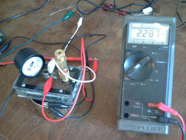 Vanadium-nickel test cell initial charging,
in transparent, openable case, with pressure gauge and adjustable
pressure relief valve,
carbon terminals top and bottom.
It appears I've finally created a good battery chemistry
based on
the designs
and chemistries I've been gradually working out over the past 3-1/2
years. In fact, I
believe it is the highest specific energy working, rechargeable aqueous
cell
made so far.
The fundamental chemistry is vanadium oxide (+) and nickel
(-) in salt solution electrolyte, yielding (to my surprise) a 2.1 volt
cell. Depending on the conductivities and current capacities eventually
achieved, this may translate to 1.75 to 2.0 volts "nominal" voltage
under load.
Vanadium
pentoxide, a somewhat lighter substance than nickel oxyhydroxide and
moving two
electrons instead of one (per metal atom), provides high amp-hours at
about +1
volt, and, rather unexpectedly, the charge and discharge products
appear to be
solids in neutral solution. (V2O5 <=> V2O3) On later inspection
the electrode appeared to be unchanged from when first installed.
The nickel as a
negative in
neutral solution, also unexpectedly, seems to have a higher reaction
voltage
than in
either alkali or acid, about -1 volt. (This seems to be a great
alternative to the manganese negatives I was doing, that seemed to be
just a little too high a voltage (around -1.37) and
consequently had a high rate of self discharge.)
Higher amp-hours times higher voltage means much higher
energy density, both by weight and by volume. Both sides are well
over 500 WH/Kg. Considering the weight of
the water, graphite, and all the things that must surround the
active electrode
materials, I tentatively estimate
that V-Ni cells could be made with a specific energy as high as 200 to
275
watt-hours per kilogram. 200 is
double the best NiMH dry cells. Lithium ion reaches up to 140 or so,
but is
typically less for larger cells that I've looked at actual specs for.
The latest lithium-sulfur cells are about 200-290 watt-hours per
kilogram. They're still experimental (with a chemistry problem yet to
be overcome), and I have little doubt
they're costly.
If for example one wanted 10 KWH of battery in a vehicle,
NiMH AA cells would weigh somewhere over 100 Kg. Lithium ion would be
similar, and lithium iron phosphate would be heavier, perhaps 150 Kg.
At 225 WH/Kg, the
V-Ni battery would weigh under 50 Kg. If lithium sulfate becomes
practical, it
might be a little lighter yet... but surely costly.
The exact workings of the cell were unexpected. It was
intended to try +nickel, -vanadium, the other way around, expecting the
very
voltage that was in fact achieved, about two volts. However, the cell
didn't seem to be
charging well in that direction - the vanadium seemed to be charging
into an
unexpected soluble state, as it appeared to be migrating. (I made this
cell from clear plexiglass and was able to see unusual activity within
the cell -- one of my brighter ideas recently.) So I tried it
the other way
around... and it worked! I didn't think the substances used would
produce such a high voltage charged in that direction, that the cell
would be about 1
volt or 1.5. But the higher energy reaction of two possible vanadium
reactions evidently
applied, and the
nickel negative voltage proved unexpectedly high, yielding exactly what
I had
intended...
and more: the vanadium "+" has substantially higher amp hours than the
nickel would have had, so less of it is required to match the negative.
(
some theoretical positrode values:
V2O5: 576.7 AH/Kg @ ~+1v = ~577 WH/Kg
Ni(OH)2: 289 AH/Kg @ ~+1v = ~289 WH/Kg
MnO2: 304 AH/Kg @ +.55v = ~167 WH/Kg
(standard dry cell)
nickel negative:
Ni: 736 AH/Kg @ -1v = 736 WH/Kg
)
Here then is what appears
to be a much superior, economical, green battery
chemistry.
To make an actually practical battery, I now hope
to
improve
the internal conductivity at least tenfold (preferably closer to a
hundredfold)
for high current EV cells. Here I struggle with the problem that
probably led
past designers to choose alkaline over salt electrolyte: that all
common metals quickly corrode away in a salt based positrode. This is
why standard dry cells have a carbon rod for their positive electrode.
Only conductive graphite and carbon products can be used. The
conductance is generally lower, and unlike metal, graphite and carbon
can't be soldered or welded to make convenient, secure connections.
The current capacities didn't even seem to match the
standard dry cell, though they were creeping into the neighborhood.
But
I've found an exciting new technique of compacting electrodes -
wetting the
substances with "Diesel Kleen" oily hexadecane solvent instead of water
- to create (probably lamellar?) structures of graphite (graphene?) and
electrode powder, creating a conductive network which gives a metallic
appearance to the electrode
surface, and lower resistances.
Finally I experimented by simply mixing graphite powder
with
epoxy, and (again somewhat to my surprise) got much better contact
between the terminal
posts and the the graphite sheets with this "glue".
And vanadium-nickel isn't
the only possible chemistry. The nickel negatrodes seem to
work well and have good voltage, giving them much more energy by weight
than as alkaline positrodes (as in Ni-MH, Ni-Cd, Ni-Fe, etc), and hence
making
the nickel much more
economical as well as smaller. They're a winner!
However, I intend to try the manganese-nickel
mix again as a positrode. If the manganese charges to permanganate as I
expect,
it should work about as well as vanadium or perhaps a little better.
And unlike vanadium, manganese is "dirt cheap", improving economy. If
not, vanadium will remain the choice, at least for vehicle batteries.
May in Brief
Someone said recently in the news - and I confess I can't
remember just who or where - that most inventors seem to be unemployed.
Well, duh! If someone is working at a job, on top of maintaining a
home, perhaps raising a family, when on earth would they be able to put
in the investment of time needed to invent and develop something new?
On the other hand, if they don't have a job, how will they remain
solvent and able to do the work at hand? With no renumeration while
working and virtually no prospect of reward even on successful
completion, most people with ideas aren't free to develop them, even if
they have all the skills necessary.
Ovshinsky had to wait until he retired to create the metal
hydride that made nickel-metal hydride batteries an excellent
chemistry (and made GM's EV-1 fabulous), using his pension as R & D
funding. He was a university
chemistry professor, yet evidently even with such credentials and such
a vision at such an institution, he wasn't permitted to do experimental
work on paid time. Without his work, NiMH batteries today would
probably still be just a scientific curiosity, not a fine product on
store shelves. He did it all
himself.
I'm able to devote my time
to inventing because I've
managed to eke out a solitary existence since 1995 without a job,
mostly by renting rooms in my house, and for several years now my
elderly mother has been sending me money. In the last three years,
Canada Revenue's SR & ED tax credit program has added a vital few
thousand dollars a year -- a partial reimbursement of each previous
year's R
& D expenses -- and having hit 55, I am now deferring my property
taxes, a major relief. (The city can have my house when I go.)
With a Department of Progress in the government, the
nation could work towards its goals of sustainability, soliciting
proposals from would-be inventors and selecting (preferably from those
with good track records) those proposals with the most
promise and seeming to offer the most "bang for the buck". Paying
individual
inventors to invent and develop targeted products would probably cost
the taxpayer far less money
than is today being shelled out for "random" untargeted R & D
funding to "innovative businesses" -- and produce tangible results and
technical
progress visible to the public. The department would naturally modify
the patent system and take other action to recoup its investments and
to see that technical advances don't go to waste. The government would
have a stake in progress instead of in stagnation.
Better motors, a superior green battery chemistry with new
techniques for making
salt electrolyte battery cells more conductive
(after over 120 years with no progress!), and perhaps soon a good
mechanical torque converter design (below) to finally allow a smaller
motor to
give more drive and batteries to go farther than is commonly thought
feasible... In all this, an
overriding goal is to point out that with just minuscule R & D
effort, with a fraction of the resources expended daily in countless
cities all over the world on petroleum engine maintenance and repairs,
the
performance bar can easily be raised significantly in key areas of
transport
technology -- and
then to prove the point by raising it myself with my own R & D.
Somehow I'd got my hopes
up about using planetary gears, but the 2.8 to 1 ratio
planetary gear performed in accordance with my lowest expectations, and
I went back to my 7
to 1
estimate as being
a good minimum ratio to put a car on the street. This would mean giving
up
on planetary gears or having a dual 4 to 1 system good for city
driving only - and even at that, with two motors instead of one, using
almost as much electricity as other systems. Two
motors at 2.8 to 1 and full motor currents just might pull it off, and
perhaps even hit 80 Km/Hr, but
I'm dubious.
I preferred giving up on the gears, and by the 4th had
worked out a new
mechanical torque converter design plus a variant, which seemed very
exciting. Later I realized
that neither would work.
I'd also been sent an idea for a new version
of Constantinesco's original oscillating masses MTC design. It used a
planetary gear! It seemed the most
promising idea. Surely in 2011 Constantinesco's 1923-26
design and product can be duplicated. But it hasn't been done yet!
Then near the end of the month, I thought of another very
simple converter idea, using springs to store potential energy instead
of inertia weights. That
would make for
less "semi-sprung" weight on the wheel. It would also be easiest to put
together, which naturally has a great appeal to me. After a number of
sketches with improving designs and ideas, I'm proceeding with it.
Finally, after last month's successful chemistry battery
cell and a perusal of
vanadium's electrochemistry, I put together one on the 6th with nickel
and vanadium electrodes and found to my surprise, first that it didn't
seem to charge as planned, and second that it not only worked if
charged backwards - not a big surprise - but it that it made a 2.1
volt cell. That was a surprise - I expected 1 or 1.5 volts, depending
on
which reaction the vanadium decided to use. It seemed the nickel
reaction (-1v) was twice the voltage (-.5v) expected from the charts.
In fact it was even better than my plan, with more
watt-hours per kilogram. I had evidently discovered a
superior positive electrode. (...for salty batteries: Vanadium wouldn't
work in acidic or alkaline cells.)
The cell still has "the usual" problems with low
conductivity, but
this month I also created a new technique for enhancing it by
compacting electrodes
with solvent instead of water, and after a promising experiment I'm
about to try out epoxied graphite
powder to connect the terminal posts to the electrodes. The next cell
may well see substantial
improvement. If the present .5 amps becomes 5 or better, it should be a
practical
battery.
The nickel (fried monel-lanthanum-bean sauce) negatrodes
seem excellent. Now I'll try the
mixed nickel-manganese again for the plus side - it seems to me those
must have been charging to potassium permanganate, and so could
work if
coupled with good minuses. This
would be even lighter than the
vanadium as they'd move three or more electrons per Mn atom, and unlike
V, Mn is
cheap... especially from used dry cells such as those currently
flooding the stores. (probably in an attempt to displace rechargeables
from the shelves.)
I didn't have time to look at the big Weel motor in May.
After waiting weeks to have rotors cut by abrasive waterjet and paying
over 350 $ for cutting to date, I'm thinking again that it would be
nice to finish that pulsejet steel plate cutter and see how it works.
And occasionally I think of my ideas for ocean wave power
and for better DSSC solar cells, without having any idea when I might
ever be able to get back to them with all the rest that's on my plate.
Hurrah to Germany for its excellent decision to phase out dangerous
nuclear power generation with its commitment to radioactive waste
storage for longer than recorded history! Hopefully now everyone else
will follow suit.
Electric Hubcap Motor System
A3938 V2 Motor Controller
I decided I really needed to have a good, high current
supply of about 18 volts - high enough to work, but not high enough
that the MOSFETs' 20 volts maximum drain to source voltage could be
exceeded to burn them out. I made a 5 volt, 30 AH NiMH battery of 12 D
cells to add to a 12 volt one to obtain this. Nice to have the lab
power supply to charge this odd voltage battery. Unfortunately the lab
supply doesn't put out quite enough current to run the motors properly
itself.
I swapped in the last A3938 chip, having burned out all
the rest, and tried a couple of times to get a motor running with it.
Mostly no current was being drawn. Some odd things were happening
and it didn't run. But (for once) I didn't get the impression there was
anything
wrong with the chip. There it sat for a while pending some inspiration.
On the 29th, I had the thought that with the slow output
slew rates, perhaps the current limiting was sampling too soon. I had
had to increase the "dead time" to the max to prevent high
'shoot-through' switching currents. "Theoretically" the dead time
should have
been overkill. Perhaps also, although the theoretical blanking time
capacitor was under 50pF and I was using 82pF, it might still be
shutting the cycle off just as it started. 1000pF was the original
value, burning out the first A3938 controllers when turned up too high.
I
put in 330pF as a compromise value.
While I was at it switched the gate resistors back from 18
to 27 ohms, nervous about burning out the A3938's gate drivers again on
my last A3938 chip. They seem to be a weak
point. On the other hand, the first controller was working (until
turned up too far) with 15 ohmers, and longer gate wires than on the
new one.
That didn't seem to do the trick. Probably I'll find
changing some component value, somewhere, will get it going. In
the meantime, perhaps next I'll try it driving single MOSFETs instead
of doubled up. (Single transistors should be fine as long as I don't
put a big load on the motor.) If that works, I'll know the slower
timings owing to the large gate charges are the source of the trouble,
instead of just guessing that's what it is. If not, I should be looking
elsewhere.
Motor Production
My enthusiasm for setting up for motor production wained
owing
to the fact that no one has ordered a fabulous Electric Hubcap motor
kit yet, because I got the flu, other projects (yardwork...
batteries!), and because it
seemed like about a month before some magnet rotors were finally cut by
Victoria Waterjet. Of course I wasn't expecting many sales until
they're pushing
cars
on the
road.
But on the 23rd to 27th I finally made some new
mold pieces for the
slightly smaller 11.25" diameter size shells, and made the 3 body
ring pieces for another motor. This diameter was
obtained by eliminating the short PVC pipe section (1/2" thick walls)
from the outer wall of the rotor compartment and instead wrapping
around several thicknesses of strong PP strapping-epoxy strapping
composite to form a thinner outer wall.
It's not the complete set of molds to allow me to cast
all the parts for a motor in one session, but it's half way there and I
can cast all the pieces, though one at a time. Between clear acrylic
battery cases and the motor body
molds, I seemed to have to cross town to the plastic supply
shop for something almost every day in this period. I thought I
already had everything, but somehow whenever I went to do something I
seemed to be missing what was needed.
My enthusiasm for the three mold system also wained
somewhat as I discovered that only one would fit in the oven at a time,
and realized that I'd need another 100 dollars worth of C-clamps to
press three at once. I'd rather spend that on epoxy to make more motor
parts, even though more slowly!
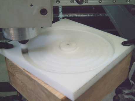 Routering the mold base. This is the second pass, deepening the dish
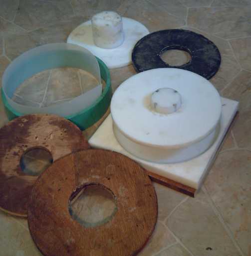 Pieces for mold(s) with 3" & 4" center posts and plywood
backings, and one finished
motor ring piece.
Pieces for mold(s) with 3" & 4" center posts and plywood
backings, and one finished
motor ring piece.
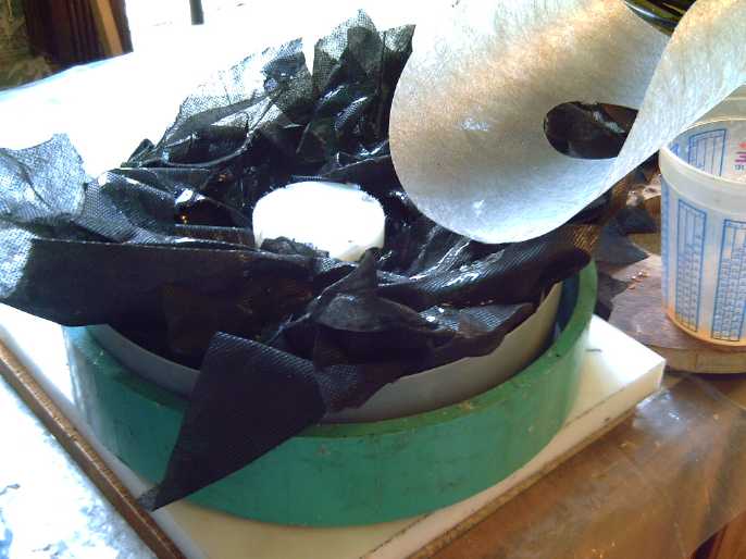 Stuffing the mold with PP fabric and epoxy resin.
The first two ring pieces didn't come out very well and
needed a lot of touching up. I got better by the third one, but I'd
like to figure out a rigid outside wall setup - I end up having to push
protruding pieces in with a chisel or screwdriver just before the
C-clamps close the gap. Nobody makes pipe the right size.
Metal Protection
Finally near the end of the month Victoria
Waterjet had cut the magnet
rotors and other parts I asked for some weeks previously. On the last
day I received back a magnet rotor that I had powder coated to protect
it from rusting. The polyester coating
looked great, and evidently there should be no problem with gluing the
magnets onto it with epoxy & PP strapping as before. I decided I
should
have the bearing holder parts coated as well. That would cover all the
main
metal parts except the axle, the SDS (magnet rotor) coupling, and the
bearings, which
would be hard to work with if they were coated.
But the powder coating place had done the rotor as a free
sample. On inquiry, it turned out it might be around 30 $ per magnet
rotor, and 15 $ per bearing holder, which there are 4 of. Doubtless
there's a lot of prep to turn them from oily and perhaps rusty steel to
spotlessly clean and shiny for coating in addition to the primer and
finish coating, but 90 $ 'extra' - on motor kits I hope to sell for 500
$ - isn't going to work. Even the 30 $ virtually doubles the cost of
the magnet rotor. I wonder if there's any way to do it, or
something similar, myself? Spray paint is probably the simple answer
for the bearing holders and maybe the back side of the magnet rotor,
but I wouldn't want flakey spray paint under the magnets. The powder
coating is good. I think I'll do a little more reading about it...
Planetary Gear Project
The results of the
first experiment seemed rather disappointing. The motor and the 2.8 to
1 planetary
gear turned fine, but it didn't budge the car, and though the motor
power
could have been doubled, it just didn't seem that could be enough to
put the car on the street. The options appeared to be the same as ever:
get a variable rate torque converter working, or the car would need two
complete motor systems even to travel at city speeds -- if even that
proved practical. (Bear in mind that most electric conversions use at
least 15 KW or 20 KW motors rather than 5 KW - only with the
exceptional performance of a mechanical torque converter have I been
expecting to drive a car with such a small motor.)
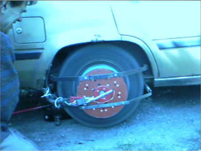 Planetary gear spin test with the wheel jacked up. This was the only
time it spun the wheel.
Planetary gear spin test with the wheel jacked up. This was the only
time it spun the wheel.
It would no doubt have at least moved the car on level pavement at full
power,
but it surely wouldn't have gone up much of a hill of a hill or
accelerated well enough for the street.
Movie: http://www.youtube.com/watch?v=Zihj3wbPe3A
If a practical mechanical torque converter was already
invented, the
choice would be simple. But it was build the second motor
system or invent the torque converter. Here I've been for two
years, thinking the later would be the superior option, and quite
possibly the faster as well. Well, it hasn't been the faster!
But someone sent me a link to an idea for a rotary
version of Constantinesco's original torque converter -- using
planetary gears! This development seemed so promising, and the
planetary
gears used in the normal way so little promising, that I decided to
try the planetary gear torque converter idea and set the 'regular'
planetary gears system aside.
Torque Converter Project
With the disappointing performance of the planetary gear, I
started thinking again about
the variable ratio mechanical torque converter (MTC), and at the same
time,
someone sent me a link to an MTC design concept someone thought of and
posted to "halfbakery.com" a couple of years ago - just a couple of
months before I started
trying to make one myself. It was essentially a rotary version of
Constantinesco's original design using oscillating planetary gears. The
'engine' oscillated the planet gear carrier back and forth, about a
90º cyclic rotation.
The sun gear shaft had a flywheel, replacing Constantinesco's original
pendulum as the oscillating mass. With my gear, that would have a speed
increase of 2.8 to 1, magnifying the effect of the flywheel's mass by
about 8 over a one to one speed arrangement. Various rotors could be
tried to see what mass works best. On the
outside, the ring gear was connected so that it would turn a one-way
ratchet as it twisted back and forth, moving the car one
direction.
It looked very promising, if a bit complex to build. I
have the gears, but still it would take a lot of
changes,
detailed design effort and work to implement.
And moving the car "one way" would mean forward only. Was
I to turn on the gas engine just to back up?
Another feature of
this converter idea was that it could be a double version, with two
masses, gear
sets, flywheels et al at 90º phase to each
other, which would
balance the load on the 'engine'. I think Constantinesco also used two
90º masses in his production model car engine. But probably for an
electric motor, there's no need to have balanced drive at all points of
rotation.
But I started
sketching and tried again to come up with something simpler. After a
couple of weeks of thinking I was really onto something and being eager
to start building, I realized neither of the two design variations I'd
come up with would work - and that one of them I had thought of before
and already gone through the same process.
Later I thought of a
couple of variations of my other new
design (not
oscillating masses) that just might work. But my confidence
level wasn't high.
At the same time, I was
starting to think of ways to put together the planetary gear type. The
planetary gears were in fact just one of the several components. It
couldn't be a simple in-line form. It would be something like a giant
size
mechanical clock, with all the shafts borne on two parallel plates of
steel and all the gears and levers between, with a few posts holding
everything rigid. Those plates would have to be at least a couple of
inches apart to hold everything, which would do nothing for thinness of
the fit outside the car wheel.
But... it ought to work! I decided I would simply have to
do it - even if it couldn't back up. Perhaps some solution for that
might develop as I worked.
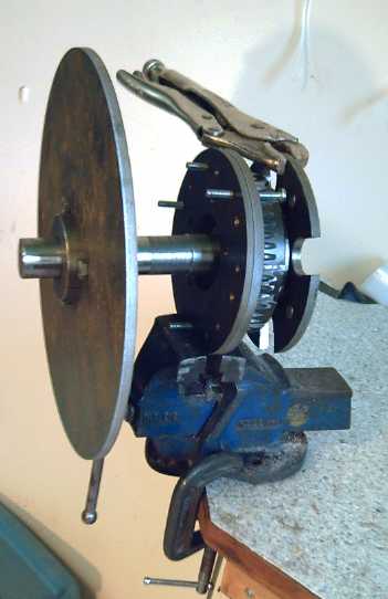 Checking out planetary gear inertial effects: put weight on one
element,
Checking out planetary gear inertial effects: put weight on one
element,
clamp another in a vise, twist the third back and forth with
vise-grips...
and see how much the narrow workbench wobbles.
The biggest sticking point
to getting it to work at all is perhaps the
"one-way valve" or ratchet that takes the oscillating motion and turns
it back into rotary motion at the wheel. Some more recent MTC
implementations have come to grief over this seemingly minor point:
commercial one-way bearings evidently aren't made to handle rapid
oscillations
- they get hot and soon burn out. I'd really like to know what
Constantinesco used in
his 1926 cars! I do however have a couple of ideas for durable
ratchets. One
uses the outside of the planetary ring gear, which is the output piece
and which has grooves... and both use the arms from my aforementioned
sketches. I did up a drawing of a design that looked workable, if a bit
complex.
---
The same person who found the halfbakery.com idea also
pointed me to the NuVinci bicycle hub, an
entirely different MTC design using tilting rolling balls, and the
various diameters attained at different rolling angles. It looked very
complicated to do and needed special 'lubricant', which is the reason
I'd passed the design over
previously.
But now a small version was actually in production, for bicycles.
Should I have another look at that before I started building the
oscillating masses type? A phrase from a blurb on the
site spells out the advantages of mechanical torque converters that
I've been mentioning:
"... it dramatically
improves acceleration, hill climbing and top-end speed while extending
range and battery life..." (www.fallbrooktech.com/09_LEV_Kit.asp)
Those features are why I expect to make a mere 5 KW motor
drive a whole car. But is there any reasonable way to make these
things, big enough for a car, without a whole factory and without
having the special
traction lubricant? (or can the lubricant be obtained?) Somehow, I
can't see trying to scale up their friction-drive unit from the weight
of a person to the weight of a car. I think any version I could build
is virtually bound to
slip and go nowhere.
But it shows there must be many ways to skin a seal
(relative of
cat)... The NuVinci uses "smooth gears" that can be varied. "CVT"s use
a belt around conical spindles. The Constantinesco type stores up
energy in an oscillating mass. Then I had a fresh idea:
Couldn't energy be stored up by compressing or
stretching a spring instead of in an oscillating mass? Or, couldn't
energy stored in a rotating mass
(rather than oscillating) be rapidly transferred by suddenly
compressing or stretching a spring?
For such an idea to work (and with all-live parts), this
would mean the motor would turn one turn (or some integral division
thereof - 1/2, 1/3... 1/16...), and then at a specific point(s) of
rotation, a
spring would suddenly transfer some of the momentum of the
motor to the output, moving it however much or little that energy had
in it to do. Naturally, the amount of energy would go up with the
square of the motor speed, and below a certain point, it wouldn't
overcome static friction.
Getting the energy transfer at specific points is the
thing. The fewer and stronger the hits, the more the chances of
each one overcoming that static friction. My last "clock escapement"
design
might have worked if there'd been just 2, 4 or 5 hits per rotation
instead of 25. (Unfortunately, with all the progress in motors, I
finally scrapped the old early 2009 motor that had those fittings,
without having tried this.)
Some mechanism would have to disengage the contact to
allow the motor to continue turning (though slightly slowed down) past
the point
of contact, and something would have to "trip" to disconnect the spring
from the output, to prevent it shoving backwards as it decompressed.
The sprung section on the end of the arm, or at the rim of
the rotor, could hit square on and rebound, then twist sideways as it
reversed, bypassing the contact point on the second pass. Once again,
I'm trying to visualize mechanical things that should be possible, but
which haven't been made before. I went off to
the drawing board to try some sketches.
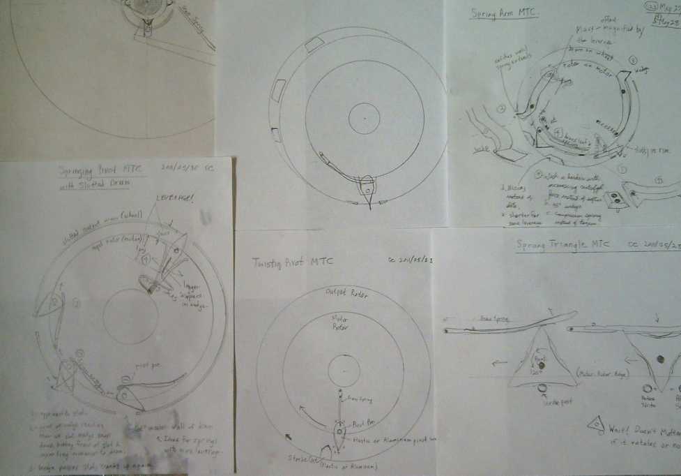 MTC Sketches of May. Top-left is one that wouldn't work from early
in the month;
MTC Sketches of May. Top-left is one that wouldn't work from early
in the month;
the rest develop the new sudden spring compression or release idea,
with spring-loaded wedges.
The first spring activated sketches (top right) seemed
plausible, but a day or two later I realized it would kick backwards
after the forwards kick, as the other slope of the wedge passed the
contact
point. The second used
triangles that would flip just once to the next face at the contact
points. Using curved faces I
tried to get a
design that would turn a little farther than flat to ensure it would
flip to the next face and not back to the first one. Then I noticed
that they would work the same whichever way they flipped! So why bother
with turning triangles? Next was the
bottom center sketch, where it just flicked it and it returned to the
same position.
Then I started thinking that all those ideas compressed
the spring
rapidly at the point of action, but it should be more energetic to have
the spring suddenly release. In the top center sketch, I
simply changed the "strike posts" to "slots" in the rim of the output
drum.
The wedge would be held pushed sideways over most of its
travel, and then
when the point reached the slot, it would suddenly snap down. If the
slot was the right length, the wedge would hit the far side of the slot
at high speed, like the sudden snap of a strong electrical switch or
circuit breaker. Then, as the motor rotor moved on, the wedge would be
twisted up again, compressing the spring, which would remain compressed
until the next slot. Note that the compressing of the spring pushes the
drum the same way as the release and immediately after it, though with
less sudden impact. The
parts will of course be greased, but any slight frictional drag of the
wedge points along the rim will also act in the same direction. None of
the force acts in the wrong direction and almost none is wasted.
In the final sketch at the lower left, I varied the
wedge shapes and spring attachments and shapes, trying to achieve best
effect. After sketching #4 in that drawing, I went from paper to 1/2"
plastic on the 31st:
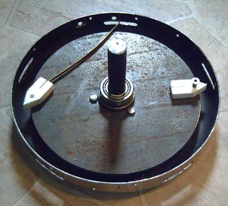 "Mock up" of sprung wedge MTC.
The number of wedges and slots will of course match so all
wedges act at once. The diameters of the rotor and the drum rim are
going to have
to be pretty close together for the wedges to engage properly. My
current
idea to proceed with is to have two thin (eg, .1") 11.5"
aluminum rotors on the motor axle (via an SDS bushing), with the
pivoting wedges between them. The
drum can be a (thicker) 12" aluminum plate on the car wheel, with the
slotted rim screwed to it. (The prototype plate may be steel as I have
one
the right size - or I might re-use the 12" frying pan for the umpteenth
time.) The axle of the motor should extend to the output
drum, where a ball bearing race will hold it centered on the wheel
center, though free to pivot a little to 'spring' the motor weight a
little vis a vis the wheel. Or (probably preferable) the output drum
may instead spin securely on the motor axle with two bearings, with a
flexible link to the car wheel (similar to last
month's wheel link for the planetary gear).
The spring tension needed to twist the wedges must be
substantially less than the torque the motor can provide to compress
them. (If less torque is required than is needed to twist the wedges,
the motor and wheel rotations will "lock" together.) I will doubtless
do a lot of playing around with the materials, sizes, shapes,
strengths, and numbers of the wedges, springs, and slots. But the basic
idea - as far as I can tell at the moment - seems sound.
Turquoise Battery Project
Salt electrolyte battery research: stalled since 1880s!
I think I've said
that
salt electrolyte seems to be about the least explored area of battery
research, much less researched than acid and alkaline. I found an 1891
book
(Primary Batteries - Henry Carhart.pdf) on
primary batteries.
It was a revelation to see the "carbon-zinc"
(manganese-zinc) dry cell, constructed in its essentials the same as
today, which (in combination with the fact that evidently no other type
of salt solution electrolyte based cells are or have ever been
available) means that no important improvements have been made
to salt
electrolyte battery cells in over 120 years! Even
then "sal
ammoniac" was apparently
almost the
only salt that was used.
Small wonder then that an 'outsider' to the
electrochemical field like me might today be able to achieve some fine
results, when it would seem no one else has
done any significant R or D on "mundane" salt batteries since Victorian
times except to improve the packaging.
But no shortage of lithium battery research
A Technology Review article (mobile.technologyreview.com/energy/37632/)
on a new "pumped
sludge" lithium battery project spells out the main problem with
lithiums:
"A big problem with the lithium-ion batteries used
in electric vehicles
and plug-in hybrids is that only about 25 percent of the battery's
volume is taken up by materials that store energy. The rest is made up
of inactive materials, such as packaging, conductive foils, and glues,
which make the batteries bulky and account for a significant part of
the cost."
This is the reason I've always felt that other chemistries
can outperform lithium: other elements theoretically have less energy
per weight, but they can be much less "diluted" in a
cell than appears to be the case with lithium types. I don't think the
"pumped sludge" approach sounds very practical for electric transport,
if for anything... though you never know! The article itself ends on
the same sort of note:
"It's a very clever device," says Dahn. "I don't
know if it will
ever
be more than an idea in a paper, but Chiang has surprised people
before."
For a doubtful "idea in a paper", the project certainly
doesn't suffer from lack of
support, having been incorporated, raised about $16,000,000 and
employed 20 people, according to the article. (I wonder how many of the
20 are actually involved
in the development, and of those, how well their time and talents are
being utilized?)
The money is somewhere around $15,990,000 more than I've
been able to put into this battery project so far. (Like I said in
"month in brief", paying individual inventors - even if they get a real
salary or equivalent plus expenses - should cost much less
than funding "innovative companies" and is more likely to produce
practical technical results. A separate problem is that even if
Chiang's battery proves practical, it is likely to end up as a patent
in
some oil company's drawer (like Chevron's 125 nickel-metal hydride
battery patents), rendered unusable by anyone until the whole
technology has been long forgotten.)
Meanwhile, back at the ranch...
Real, Solid Electrodes
In disassembling recent previous cells, I've been finding
that the electrodes (particularly the negatrodes) have become quite
hard, seemingly much harder than
when installed. They are in line with what is found inside, eg,
commercial Ni-MH or Ni-Cd dry cells. The "sandstone" texture I've been
trying to achieve in
the compactor is finally achieved in the cell itself. Evidently I've
been doing better on this score than I thought.
Vanadium negative?: -1 volts, total 2 volts --- ?
It seemed the main reason for the high self discharging
was that the manganese reaction voltage
[Mn + 2 OH- <=> Mn(OH)2, e= -1.37 V(?) in neutral
solution] was just a little too high, even with the egg albumin to
raise the hydrogen generation voltage, so the discharge reaction
happens fairly
slowly but spontaneously and continuously until the negatrode is
discharged. Iron also seemed to discharge spontaneously.
This was unexpected since it works well in alkaline solution - Jungner
and Edison manufactured nickel-iron batteries, and Ni-Fe dry cells have
recently been created in India. It led me to assume the problem wasn't
in the negative electrode, when in fact it was - with both substances.
What then could be used? Nickel worked, as shown in my
cell at the end of April, but it looked like it would be only 1/2 a
volt. What was between
-.5 and -1.37 volts?
The next element down from manganese seemed to be zinc at
about -1 volt, but the soluble zincate ion causes seemingly insoluble
problems and short life. Chromium looked similar.
Vanadium appeared to have an ideal reaction of about -1
volts with no soluble ions shown for alkaline solution. [V + 2
OH- <=> VO + H2O + 2e-, e= -.975 V(?) in neutral
solution] Drawback seemed to be that like chromium its compounds are
poisonous. But only to people -- to the environment it's "green".
(Well, actually yellow.)
 States and voltages of Vanadium - shown as usual for acid and
alkali but not in neutral salt solution -
States and voltages of Vanadium - shown as usual for acid and
alkali but not in neutral salt solution -
suggesting it might be a good negative going between V and VO at maybe
-1 volts.
Wikipedia info suggested it might dissolve into ions, notwithstanding
the insolubility of VO.
In fact, the direct reaction right from valence 0 to 5 isn't seen in
other elements.
I bought a 1/4 pound bag of
vanadium pentoxide at Victoria Clay Arts - 12.95$ ++. This price seemed
similar to nickel oxide - not dirt cheap, but not really rare, either.
(I'm guessing a 10 pound bag will have a better discount than nickel
but I haven't tried pricing it yet.) It must be borne in mind that if
double the energy density by weight is achieved, it effectively cuts
the cost in half as well as the battery size and weight.
I picked up their pound of
neodydmium oxide while I was there, which had been sitting there for
years. (As pottery glazes: intense yellow
(V) and delicate yellow (Nd).) Neo is probably better than lanthanum
for raising
oxygen overvoltage, though not as good as samarium. He had finally put
a price on it, and for 17.95 $ I could
hardly resist - after all I paid over 200 $ for 2 Kg of lanthanum I
bought early
in the project and then had to turn into hydroxide myself. (it made
about 7 pounds of it.) Samarium would doubtless be more.
Next on the
agenda seemed to be to make a new battery in a new case - hopefully
that wouldn't leak. January's ABS case, reused a couple of times, was
split
wide open at a seam. I
decided the case I'd made with a longer rod of carbon inside - and two
holes - was much
too likely to leak and abandoned it. I used clear acrylic
plastic on all sides in case there was anything to see inside the cell
at any time. Also it's harder and stiffer than ABS - perhaps that
would help prevent leaks. The clear case proved absolutely valuable for
seeing things happening inside and
I won't make any other again, at least not for prototyping. In addition
this stiffer material held pressure without leaking. I also
made
this one a little taller so there
could be a pool of water over the electrodes for a sealed (or not) wet
cell.
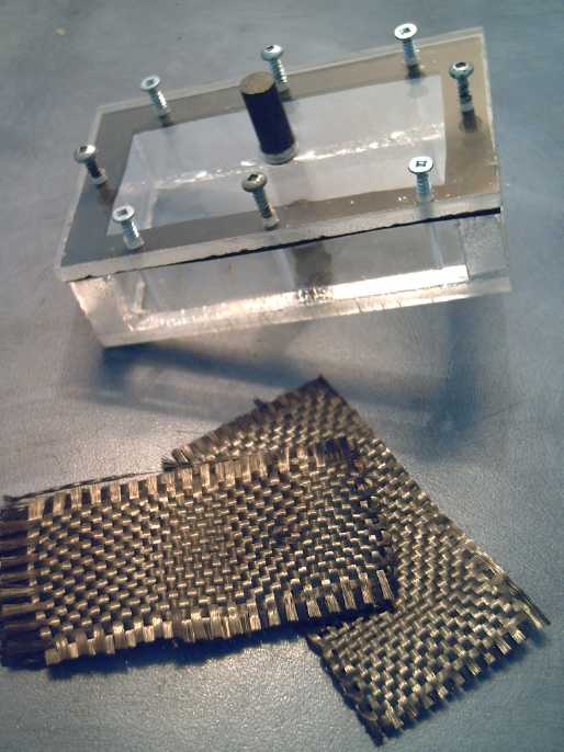 Clear battery cell case with carbon rod terminal posts,
carbon fiber mat to back the electrodes.
For the collector sheets I cut 1.5" x 3" pieces of carbon
(graphite) fiber sheets and boiled them in hexadecane (this time
outdoors, as
it reeks and I have no fume hood). It was still slightly damp with
hexadecane when I put it into the compactor. The hexadecane seems to
act as a "flux" that helps to join the electrode to the graphite for a
better connection and I'll probably continue doing it this way. The
fiber sheets didn't come loose from the electrodes. All or most of the
expanded graphite sheets have done so.
Note: The bottle labelled "Diesel Kleen" that I've been calling
"hexadecane" contains not only
hexadecane but unspecified "petroleum distillates" (from MSDS...
probably Ethylbenzene, Naphthalene, Xylene and 1,2,4-Trimethylbenzene)
and "slick diesel"(?), in unspecified proportions. Whatever it exactly
is,
it seems to work great! (Likeliest best ingredient: methylbenzene?)
Pos (Neg):
- 15g of the monel/La(OH)3 mix
- 10g of MnO2/graphite mix (from a dry cell)
- 5g more graphite powder
- .25g Sb4O6
- 1.5g Sunlight
- bit of HOH
(No MnO2 2nd cell)
This 'trode was compacted onto the treated carbon fibre,
painted with lime, dried in the oven for 40 minutes at 250ºF,
torched for 10 seconds, and then
placed in the bottom of the new cell case.
I was in a bit of a hurry and only dried it in the oven
for 2/3 of an hour. In the torching, a chunk popped out. They get the
full hour drying in the oven from now on!
Neg (Pos):
- 12g V2O5
- 9g graphite
- .15g Sb4O6
- 1g Sunlight
- bit of HOH
The "intense yellow glaze" vanadium pentoxide made a
yellowish electrode
instead of the usual dark gray to black.
For the separator I used only a sheet of cellophane, doped
with osmium in acetaldehyde. If it's too thin and shorts out, I'll have
to dig out the vanadium electrode and replace with cellophane and art
paper, but thin should make for great ion flow - gotta get that
internal
resistance down.
As an aside, there were separator sheet materials/textures
I was thinking of long ago (and probably won't use now), that I
couldn't think what it was I was thinking of. One of them I
finally realized was coffee filter paper. The other was polypropylene
non-woven fabric, which I didn't know is also called "landscaping
fabric". However, the fabric is too
porous and the electrodes would short. Coffee filters remain possible,
but are probably not as good as the Arches watercolour paper... though
it may depend on brand. So does the watercolour paper.
Using clear plexiglass for the case was quickly
vindicated. A visual inspection of the cell after a few hours revealed
that some vanadium oxide had gone through to the lower electrode in one
corner - leaked or fallen over the edge of the cellophane "tray". The
rest of the negatrode had lost its yellow colour and turned black over
a few hours, presumably as it charged to lower oxides or to vanadium
metal, but
distinct yellowish patches were there around the edge spreading
from that corner. If this battery has any self discharge, fast or slow,
there was the first item to suspect. Perhaps that was part of why it
seemed to be charging so slowly, and why the voltage rapidly dropped
off if the charge was removed.
How many previous cells might I have seen and solved
problems in if I'd made them all clear?
It didn't seem to want to charge. After a while I took it
apart and put
in another sheet of cellophane, but that didn't help - the yellow edges
spread.
Perhaps there was something odd going on, with all
vanadium's odd soluble reactions spoken of on Wikipedia? The redox
chart did show a reaction straight from valence 0 to 5, which seemed
unique. Perhaps it became some dissolved ion form not shown, went
through the separator, and recharged at the positrode to valence 5?
That
might explain the migration seen
at the edges.
But if it wouldn't work as a negatrode, could vanadium
make a good positrode? With all the strange "+" oxidizing reactions of
vanadium in "strong acid" and "strong base" forming various soluble
ions, it didn't seem very
likely, but as usual there's no redox charts of vanadium in neutral
salt
solution. Vanadium pentoxide is "the most stable and common compound of
vanadium", which "upon heating reversibly loses oxygen". I also gleaned
from one item that the tetravalent state is, or at least
sometimes is, V2O4 rather than VO2, and the trivalent state is V2O3. It
is perhaps noteworthy that the
cation in the main positive states of charge should be "V2", suggesting
a
good stability between charge and discharge.
Conceivably in salt solution it might discharge and charge
between V2O3 [III] and V2O4 [IV], moving one electron per reaction, or
(better still) V2O3 and V2O5 [V], a valence change of two electrons?
This last reaction, illustrating
the "reversibly losing oxygen" property of V2O5, looked on the chart
like it might occur at
about the desired +1 volts, which would make vanadium an excellent
positrode material. There are also various transition oxide forms
between
V2O3 and V2O5, such as V3O5 and V3O7 that vanadium can take... as well
as various soluble ion forms. But it seemed more likely the V2 form
would
remain intact as two oxygen ions came and went, and solubles might well
only
occur in acidic or alkaline solutions - not in neutral salt and with a
"+" charge.
So I tried what I tried with the
previous battery (and once in a long distance phone call): I reversed
the charges. I now knew that the nickel
works as a negative. This seemed to charge! After 12 hours, a bit of
yellow
colour seemed to return, so evidently it was charging back to valence
five -- perhaps to V2O5 in accordance with my fondest hopes. And the
cell voltage had risen to around 1.7 volts and was still rising.
This was another surprise. It had seemed to me the most
likely reason the previous cell was 1.5 volts was that the manganese
was charging to potassium permanganate (+1v) and that the nickel
hydroxide to metal would
be -.5 volts, midway between the base (-.72v) and acid (-.28v) levels.
But for the vanadium at about +1 to cause the cell to rise
to
a
higher voltage meant that to explain the previous cell's 1.5 volts, the
"-" side must have accounted for more of the voltage. The "+" then was
actually charging to only MnO2 (+.5), and the
nickel-manganese-lanthanum side in salt had to be about -1. There is,
eg, a redox reaction for NiS <=> Ni that's -.99 volts, but it's a
far cry from
anything shown on the chart for oxides/hydroxides.
 Nothing in the chart hints that Ni(OH)2
<=> Ni is apparently -1 volt in salt solution,
Nothing in the chart hints that Ni(OH)2
<=> Ni is apparently -1 volt in salt solution,
instead of being be the average of the acid and alkali levels.
In vanadium, seemingly I've stumbled across an excellent
battery
positrode
substance. How good? Wow!:
(a) The only reaction suggested by the voltage would be V2O5 <=>
V2O3. Theoretically this reaction moves two electrons per vanadium
atom. It looks to me likely it will actually
approach this value in practice. Manganese dioxide is said to move one,
and
nickel (with the best mixes - which significantly dilute the actual
nickel content) moves about 1.5,
so 2 (and without additives) is a major gain.
(b) V2O3 (@4.87
g/cc) is a little more dense than nickel hydroxide (@4.10), and it is
only slightly less dense
than MnO2 (@5.03), but it has the lightest atomic weight, so it packs
in
more atoms -- more amp-hours -- both by weight and by
volume. Even if NiOOH, MnO2 and V2O5 each moved just
one
electron per metal atom, the amp-hours of the vanadium both by weight
and volume would still be highest.
NiOOH <=> Ni(OH)2 - 102<=>103 g/m, 1 e- (1.5 e- with best
mixes charging some to NiO2)
MnO2 <=> MnOOH - 87<=>88 g/m, 1 e-
V2O5 <=> V2O3 - 91<=>75 g/m, 2 e- (grams/mole &
electrons for each "V")
(c) With the dual vanadium
center, it may prove to be the most stable and have the longest cycle
life - if it has any cycle life limit at all.
(d) It's "the max" +1 volts instead of
some lower voltage. (Though, in neutral solution, nickel should also be
+1. V2O5 and NiOOH might even make a good mix, if there seems to be any
reason not to use just V2O5.) The higher the voltage, the higher the
energy density, and +1 and -1 seem to be about the limits in salt.
Thus vanadium looks excellent for a "regular" type
battery,
ie one with solid electrodes, in salty electrolyte. (It's also used in
the "vanadium redox
battery" in liquid form.)
I don't know what vanadium's problem is as a negative -
perhaps with the right treatment that could work too, but I didn't seem
to be getting good results. Or perhaps like nickel, and maybe iron, the
hydroxide to metal voltage was
higher in neutral salt solution than expected, which could make it too
high. (Could this be the general case? It would explain
why salt water is so corrosive, and why "low voltage" nickel is -1
volt.)
If the nickel is about -1
volts, it's higher than in either acid (-.28) or alkali (-.72). But
that would seem to be the best explanation for getting about 2 volts.
It can't be the lanthanum, and copper has no reactions that look like
any sort of match. I added no manganese to the nickel mix in the
second cell, so it wasn't the manganese.
What a round-about way to arrive at my "ideal" 2 volt salt
solution battery cell - one reaction unexpectedly without soluble
products in charge or discharge, and one
reaction whose voltage in salt is quite unexpected, neither really
hinted at
or suggested in the charts and literature! But the result is the thing
- a better battery chemistry! I'm going to make a preliminary estimate
that it's good for 200-275 WH per Kg. Only the newest, experimental,
lithium-sulfur
cells (220-290) rival that,
and it should be far more economical to produce than those.
Also, batteries have specific causes for eventually
wearing out or failing, and I haven't identified any so far except for
potential eventual drying out of the electrolyte through poor seals.
Since it's a flooded cell type, it can be refilled by drilling a tiny
hole in the top, adding water, eg with a syringe, and putting in a
plug. That means I'm guessing they should go until the plastic case
finally
cracks or the separator disintegrates. (I should probably put in a
combo filler/relief cap that releases gas above a certain pressure.)
After charging the cell, I let it sit and found it
discharged overnight to about 1.1 volts. I charged it again and did a
50 ohm load test. The internal resistance was higher than previous
recent cells and it didn't fare well.
I took it apart and added sheets of expanded graphite,
sanded to roughen and cleaned with hexadecane, and hexadecane
brushed onto the carbon fibre cloth, which did come apart from the
electrode briquettes on disassembly. The brushing seemed to loosen the
fibres - perhaps that will improve conductivity. The graphite parts
were still wet with it when I put them back together with the 'trodes,
which may also help.
But I didn't put the vanadium positrode back in. Instead I made a new
one, adding some nickel hydroxide and neodymium oxide in hopes of
reducing the self discharge.
Pos):
- 9g V2O5
- 9g graphite
- .10g Sb4O6
- 4g Ni(OH)2
- 2g Nd2O3
- 1.5g Sunlight
- bit of HOH
This upped the current capacity to about what I had with other cells,
but it didn't seem to do a thing for the self discharge. Had I in
vanadium oxide picked another element and reaction that was just a bit
too
high in voltage? Considering how close it must be, with the potential
not only of almost double the voltage of manganese dioxide, but also of
moving two
electrons per metal atom instead of one, that would be frustrating.
Days later I realized I'd forgotten the calcium layer for
overvoltage improvement, as well as the idea of adding cobalt oxide to
increase conductivity. I should really get into a better habit when
doing electrodes - post procedure notes on the wall and check them as I
proceed!
A load test before and after seemed to show that the
voltage stayed higher longer for half an hour or so, but then dropped
off to even lower levels thereafter.
I took it apart and put in a calcium layer and torched it
(in fact I did two, unthinkingly placing one on the nickel electrode
instead of the vanadium one... well, that was the original "+" side, on
the bottom of the cell where I put the "+"es... and I had the flu.),
but by this time the briquettes were crumbling and there was little
hope of better current capacity or performance. I also replaced the
cellophane separator sheet (ripped) and added some more osmium powder
to the acetaldehyde mix before coating it.
The reassembled cell seemed to have higher self discharge
and took considerably longer to charge than before. A positive note to
that is that the self discharge, being higher, seemed to be something
I'd done
rather than to be an intrinsic property of the materials.
The chemistry seems good, and (for once!) the cell holds
pressure: the
conductance simply has to be improved. That may well solve the self
discharge and the low utilization of the electrode substances. It's got
under 20mA/sq.cm. even through 1 ohm, which is nearly a short circuit
with such low values. Ten times that figure would be a great
improvement. I could add bits of carbon (graphite) fiber to the
electrode as well as the powder, but I hate working with it - it's
worse than fibreglass and I end up itchy from the fine fibers every
time I use it. I can also add cobalt oxide, but that's supposed to form
a conductive network "in solid solution" with nickel hydroxide, in
alkaline solution. There's no guarantee it'll help simply mixed with
vanadium. There may be many possibilities for improving salt
electrolyte cell characteristics, but salt solution batteries and ideas
for them are hardly in the literature.
On the 13th I chopped up some carbon fiber mat into small
individual strands, maybe .05" to .25" long, and immersed it in
hexadecane. I realized I could probably use hexadecane to wet down the
electrode mix as easily as water. It would evaporate, and it seemed it
might improve contacts - and also keep the lightweight fibers from
becoming airborne while working.
I suspected that nickel hydroxide might either complement
the vanadium oxide or raise its oxygen overvoltage. So Vanadium
Electrode Mix #3 was:
10g (66%) V2O5 (active)
5g (33%) Ni(OH)2 (overvoltage/active)
.15g (1%) Sb4O6* (O2 H2 => H2O recombinant catalyst)
5g graphite powder (conducts)
"a 3g wad of" carbon fiber (conducts) [much of the mass of the "wad"
was hexadecane.]
1g Sunlight (glue)
?? hexadecane (flux)
*I want to try Sb2S3 (Sb4S6?), stibnite
- might work better - but I haven't found a cheap and convenient source
for it yet. It's sold by pyrotechnics supplys, but I couldn't find a
Canadian source, and the shipping from the USA was much more than the
price of the merchandise. I could make Sb2(SO4)3 by boiling the Sb2O3
in sulfuric acid - perhaps
that might reduce to Sb2S3 in the negative electrode? Yuk!
This electrode was compacted
on a sheet of expanded graphite. Taking off the graphite sheet revealed
an amazing working of the Diesel Kleen solvent: what would normally
have a
fine
"sandstone"
texture instead had a smooth metallic sheen and very low electrical
resistance, adjacent points reading as low as 4 ohms. This appears to
be
a fabulous technique for improving conductivity! I suspect it's forming
random lamellar
structures of graphite (graphene?) and electrode active substance(s) as
it evaporates, a random conductive network through the electrode.
(Perhaps I can dispense with the nasty chopped carbon fibers?)
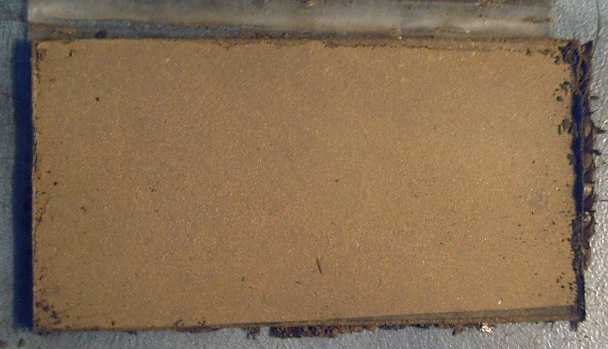
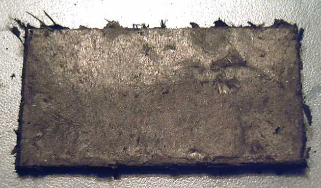
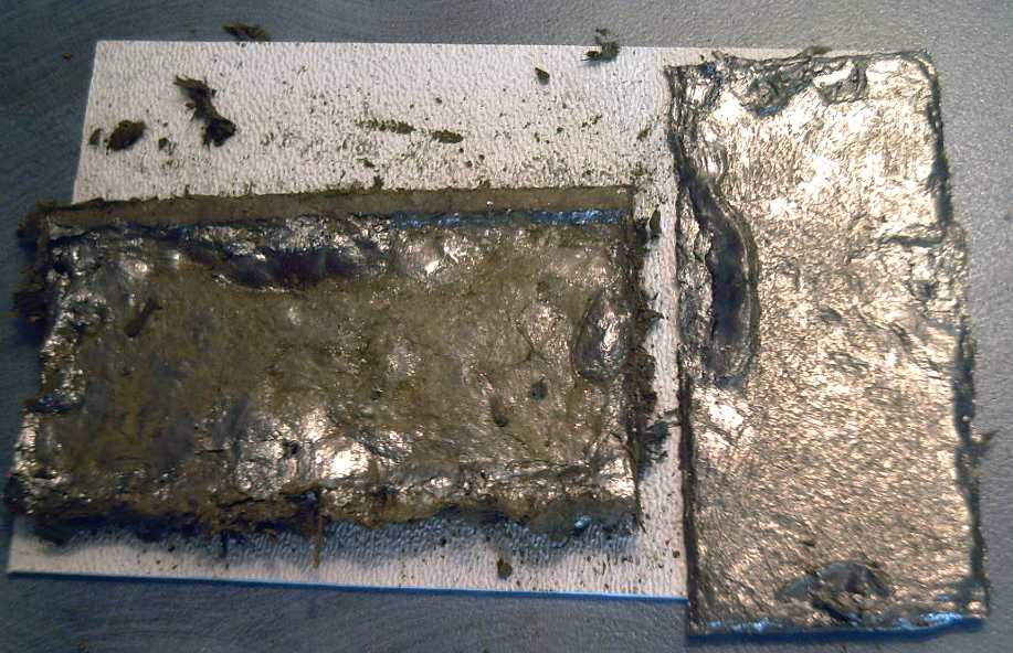 Backside of vanadium electrode briquette, with a metallic sheen, and
fuzzy with conductive carbon fibers (left),
Backside of vanadium electrode briquette, with a metallic sheen, and
fuzzy with conductive carbon fibers (left),
with its expanded graphite
backing sheet (right), illustrates the effect of the solvent/hexadecane.
A more usual electrode surface texture is seen in the thin area
along the top, which protruded past
the backing sheet.
The rest has a metallic sheen to it and quite low
electrical resistance.
(Note: The backing sheet is somewhat lumpy and the worse for
wear after 3 compactions. The first 2 compactions failed because the
briquette was too damp with
hexadecane and oozed out of the form. "Diesel Kleen" seems to evaporate
considerably slower than water.)
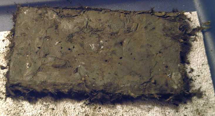 Top face of the hairy electrode. A few surface spots had a silver
shine to them.
Top face of the hairy electrode. A few surface spots had a silver
shine to them.
With the addition of nickel hydroxide to the vanadium pentoxide,
electrode color went from ecru to camo.
However, with only 5 grams of graphite powder in the mix,
the resistance from the top face to the bottom seemed to be in the mid
tens (~50) of ohms. I should have used more powder. Next
time I will -- and that'll be soon if the cell doesn't perform well.
So Vanadium Positrode Mix #4 (barring further adjustments) will
be:
10g (66%) V2O5 (active)
5g (33%) Ni(OH)2 (overvoltage/active)
.15g (1%) Sb4O6* (O2 H2 => H2O recombinant catalyst)
8g graphite powder (conducts)
"a 3g wad of" carbon fiber (conducts) [much of the mass of the "wad"
was hexadecane.]
1g Sunlight (glue)
?? Diesel Kleen (solvent/flux)
Next the layer of calcium
hydroxide was painted on, then it was dried in the oven
for about 90 minutes at 225ºF, and then torched for 7 or 8
seconds or so with a swirljet (very hot) propane torch, moving the
flame around the surface to hit it all.
For the negative, I used the Ni-Mn-La mixture at the top of this
article except I used 7.5g graphite, .15g Sb4O6, and a ~2.4g wad of
carbon fiber, and wetted it with hexadecane instead of water. Only
about 3/4 of the mix seemed to fit into the compactor, so some was left
over.
This time
I was afraid to add too much hexadecane, and it came out of the
compactor rather dry. The metallic sheen covered only a portion of the
back surface. Unsatisfied, I dabbed on some more hexadecane and
re-compacted it. This time, the briquette had to be pried away from the
graphite sheet, and the whole surface was silvery. (A couple of silvery
briquette surface spots broke away and stayed adhered to the graphite
sheet - they weren't 'missed'.)
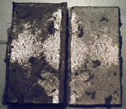
 Left: First try - too dry. Not enough hexadecane, and silvery
surface coverage was incomplete.
Left: First try - too dry. Not enough hexadecane, and silvery
surface coverage was incomplete.
Right: Added a few drops to the bad areas and re-compacted. This
completed the coverage.
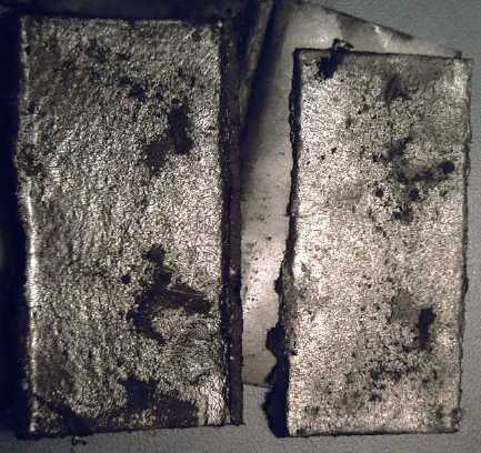
 The front surface, also looking a bit silvery. Resistances were
quite low,
The front surface, also looking a bit silvery. Resistances were
quite low,
around 10 ohms from surface points to the graphite backing sheet.
After compaction, resistances from any surface point to
the backing sheet seemed to be about 10 ohms. In these silvery surfaces
I felt, for the first time since being forced to adopt carbon instead
of metal backings and conductivity additives, that high current
densities might be within reach. ...as long as the electrodes haven't
become more or less impervious to the electrolyte (unlikely), and as
long as those nasty carbon
fibers don't poke their way through the separator sheets and short out
the cell! I suspect the fibers are now superfluous, though.
After a day of charging the cell, it was up to almost 2.2 volts, and it
would source around 3/4 of an amp into a one ohm load, only a small
improvement over previous cells. That would be maybe 30mA/sq.cm of
electrode interface. An order of magnitude more would be better. It
wasn't as good as a new regular manganese-zinc D cell (1.275 A), but it
was headed the right direction. The D cell would be about 50 sq.cm
instead of 29 though, so 26 mA/sq.cm. (I found it was capable of 40
mA/sq.cm while delivering above one volt. What a far cry such numbers
are
from NiMH D cells, delivering 70 amps at almost a volt to start the
car!)
I was hoping for better. Doubtless it would have done
better with a little more
graphite in the positive to reduce those 50 ohm readings, and probably
if I hadn't split the carbon sheets away from the electrodes to peek in
between. In a future cell I can also try using metal (expanded copper
mesh?) in the negatrode structure to provide lower resistance in that
side.
After a second day's charging, green material had formed
around the edges on the negatrode and started creeping its way up the
folded separator sheet to the positive. It could be nickel hydroxide or
copper chloride - they're virtually identical blueish green. On the
other hand, nickel hydroxide shouldn't be moving, and copper chloride,
even if it formed,
should have converted to hydroxide (or dissolved). Furthermore, both Ni
and Cu should be reducing
to metal with charge, not oxidizing. Whatever it is, I don't like the
way it's trying to do an end run around the separator!
By the end of the day, black lines were forming at the
tops of the green. Best guess: it was Ni(OH)2 and it had now touched
the positrode, and was charging up to black NiOOH on top. A bridge
around the edge of the separator sheet -- it's a sure setup for rapid
self discharge! I let the cell sit overnight and charged it during the
day, and sure enough, on the second night, the voltage in the morning
was lower, 1.3xx versus 1.6xx volts.
I disassembled the cell. The positrode came out without
damage, and I wrapped it almost all up in new paper except where it had
to contact the terminal post. Not only was this better insulation with
less chance of a bridge, it turned out to be easier to fold than
forming a dish
around the outside. It did use a 3x4" piece of paper for a 1.5x3" area,
but paper is neither pricey nor heavy. I added a couple more sheets of
rubbery stuff, hoping a stronger press would get everything connecting
together better inside.
The old paper was green not only around the edges; much of
it was impregnated with green, in many areas black on the positive side
surface. If this was copper chloride, it could possibly be an
advantage, just as
zinc chloride proved to be a better electrolyte in standard dry cells,
and it then became a specific additive to improve performance. If it
was nickel, either hydroxide or chloride, it was probably bad news.
Nothing for it but to put it back together and see what happened. And
maybe figure out some chemical test for copper or nickel on the old
paper.
How could I have made all those cells without clear sides
to see in!?!
I put a pressure gauge on this cell, but I unscrewed it
and let the pressure out whenever it hit about 3 PSI. I think a flooded
type cell with an air reservoir on top and a pressure release valve
will be optimum, especially for DIY construction. Somebody else can try
completely sealed cells (dry or wet) later. This will also be about the
safest battery going: it can't pressurize and explode, and salty water
isn't
corrosive to human flesh if it gets out. Short of actually ingesting it
- or perhaps leaving it short circuited until things start to melt -
it's unlikely to injure anyone.
On the 19th I finally bought an adapter fitting for
the adjustable pressure relief valve I had bought along with the
pressure meter, well over a year ago now, and I installed the valve.
Now it could do its own pressure reliefs when and as needed, at maybe 5
or 10 PSI.
V-Ni cell in clear case with pressure meter and pressure release
valve.
Greenish layer is nickel negatrode, white is vanadium pentoxide
positrode wrapped in watercolor paper.
Brown is spongy rubbery stuff to push the two together.
5/16" carbon posts top and bottom (from standard "D" cells) connect the
electrodes to the outside world.
On the 20th the voltage had
dropped overnight again to 1.64 volts. I thought of opening the cell
and adding eggwhite/albumin to the negative. But it already had the
thiamin - surely a good amine itself. When connected, the voltage rose
to 2.1 in a couple of minutes, more like a commercial battery. It
seemed the 'intermediary' additives had been charged out and all that
was left active was the intended chemicals.
Something seemed to be changing, and one must expect very gradual
results when charging a cell that's several amp-hours at 25mA. I
decided to give it another day of charging and see what happened on the
fourth night. It could take the rest of the month to really see
results, but I'd rather take it slowly. If it appeared to be working I
might make my 'full size' 3" x 6" cell.
The next morning the voltage had dropped even more, to
1.54 volts. All that green stuff around the edges... it came to my mind
that I hadn't added the zircon ion shield layer, at least not to the
second separator sheet. In the afternoon I opened it and painted some
zircon on. (I'd better not forget the zircon if I try the
manganese-nickel mix for permanganate again!) I also added yet another
sheet of rubbery mat stuff to push the electrodes together more.
It didn't help. Conductivity seemed to be gradually
dropping. It would only source 1/2 an amp into 1 ohm, and the following
morning the voltage was 1.46. I decided to charge it backwards and see
what happened, this time not to attempt to use it that way, but only to
change or move chemicals that might have charged up on the wrong sides
or in a wrong way. I charged it much of the day that way, then reversed
it again.
There was improvement - after 8 hours sitting the cell was
still 1.65 volts, and 1.5 volts after 18 hours. At least it was back to
how it was. I let it rest the whole of the 23rd.
On the 23rd also, I was given a PDF copy of Battery
Reference Book 3rd Edition by T.R. Crompton - a 774 page tome.
Imagine working on making batteries for 3-1/2 years, doing web searches
and looking at library catalogs, and not discovering that such a
comprehensive reference work exists! Could it have saved me countless
hours of work? Or would I have been "indoctrinated" with "standard"
assumptions and not tried some of the things that are now starting to
yield great results? Starting with a "clean slate" (also known as
complete ignorance) and perhaps discovering some thing or things
overlooked by previous battery research was after all one of my ideas.
However, as I perused some of the pages, I found practical
design and construction seemed to be about the least covered aspect. In
particular, I could find no mention of why only carbon and graphite
were used for common dry cells - that every metal placed in the
positive electrode would corrode away. Essentially it didn't seem to
contain any revelations that
would
have really speeded up my work.
On the 24th, it finally dawned on me that it might simply
take a few charge, rest, and discharge cycles to get everything
into proper balance. I'd done lots of charging but until now little
discharging or resting on this cell. Having rest it over 24 hours (it
was still about 1.4 volts), I shorted it out for a few hours until the
current dropped to almost nothing, then let it rest some more, and
charged it in the evening. On the 25th it still wouldn't source more
than 450 mA into a one ohm load, and a load test didn't seem very good,
notwithstanding that it wasn't very fully charged.
The Conductivity Problem: Epoxy-graphite experiment
The chemistry (and probably more than one chemistry) seems
great, the electrode conductivity is surely much improved by compacting
with Diesel Kleen. The external metal clamps seem to contact the carbon
posts quite well. Where then is the performance problem? No amount of
charging and discharging seems to improve conductivity, nor restore it
from its slow decline in each cell. There seemed to be just one likely
culprit: the contact between the graphite backing sheet and the carbon
terminal post. These two pressure-contact-only joins, where the
graphite sheet would gradually saturate, surely deform and get looser
under
pressure, were now the one unvarying "worst feature" of all the
cells I've been making, which are all two or three internal ohms to
start and which all only put out 1/2 an amp or so, and that get very
gradually worse.
I visited graphitestore.com on the web and started
wandering around the pages. After looking at a few things of marginal
interest, I found some "conductive epoxy" glues with metal particles in
them - silver, nickel, or aluminum. But if the electrolyte soaks
through the graphite sheet and comes into contact with a metal at the
positive electrode, it'll oxidize into a low conductivity oxide. If the
metal particles contacted each other - as they must to conduct - they
would all eventually oxidize.
Okay then, how about epoxy with carbon or graphite
particles? What about simply mixing graphite powder with epoxy? Mixing
graphite into pitch gave poor results, but I hadn't tried epoxy.
As a preliminary experiment, I mixed a little epoxy, 3.65 g, and then
stirred in a gram of graphite. It turned black, but the consistency was
little changed. I added a second gram, and it became a little thicker.
With a third gram it became a thin paste, and with a fourth, a thick
paste. With a fifth gram it all stuck to the stir stick and came out
with it. It also lost its shiny appearance - it was getting dry with
graphite.
Between each graphite adding, I placed a drop on a small
sheet of expanded graphite. With the three grams
and four grams pastes, I also stuck two little stub carbon electrodes
onto the sheet. I "caulked" some excess around their bases for more
contact area. For the five grams, I wasn't sure the epoxy would "wet"
the carbon and the graphite and get a good grip... and I was out of
stub electrodes and the little sheet was full.
From a consistency perspective, the 4 grams of graphite in
3.65 grams of epoxy - about 1 to 1 or a bit more of the powder - seemed
about right for gluing carbon terminals onto graphite sheets. But how
was it for conductivity?
Before the epoxy set, I measured some resistances.
Unfortunately, a lot depends on contact pressure, readings vary, and
such low resistances are virtually beneath my meter's scale. But here
are typical readings for what they're worth:
.3 Ω - touch cleaned meter leeds together ("0 Ω" calibration)
.4 Ω - any(?) two points on graphite sheet
.5 Ω - top of "4g" electrode to graphite sheet
.7 Ω - top of "3g" electrode to graphite sheet
After the epoxy set, readings were taken from each droplet
and from the two carbon posts, to the graphite sheet:
.2 Ω - cleaned meter leeds (or .3 Ω)
.4 Ω - two points on sheet (or two points on the same carbon post,
either post)
∞ - 1g droplet
∞ - 2g
100,000 Ω - 3g
1000 Ω - 4g
150 Ω - 5g
.7 Ω - 3g post
.5 Ω - 4g post
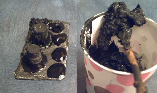 Epoxy mixed with graphite in varying proportions, glued to an
expanded
graphite sheet.
Epoxy mixed with graphite in varying proportions, glued to an
expanded
graphite sheet.
A little over 1 part graphite powder per 1 part epoxy resin by weight
seemed like good glue.
A little more graphite (~4:3) and it all stuck to the stir stick
(right), but seemed to adhere well
(top left corner of sheet, behind rear "4 grams" terminal post) and had
the lowest contact
resistance.
I tried to pry the 5g droplet off to see how well it had adhered. It
broke off, but it seemed to have taken a surface layer of the graphite
sheet with it. The same thing happened with the 4g droplet and the 2g
droplet when I pried on them. Evidently the glue at any concentration
sticks well and is stronger than the flakey graphite sheet it adheres
to. Owing to the fragility of the sheet one evidently must be careful
not to break the post off it during battery assembly.
Conclusions: It works! A terminal post made
out of
graphited epoxy would have high resistance, but as a conductive glue to
hold the carbon post to the sheet it seems to work quite well.
Certainly the more graphite powder in the epoxy the better the
conductivity, and there's a threshold at about 1 to 1 below which
conductivity is very poor. Somewhere between 4 and 5 grams of graphite
(per
3.65 grams of epoxy) may be an optimum ratio, eg, 5 to 4. With too much
graphite
the mix probably won't adhere well and at some point will become
unusable, or porous. On the other hand, the more the graphite, the
lower the
resistance.
I rolled the leftover 5g mix into a thin sheet, thinking
it may make a good electrolyte-impervious conductor for separating
bipolar cells to make multi-cell, higher voltage batteries in one case.
It became quite shiny again. The contact resistance was high, in the
kilohms (in the thick areas)
and up to megohms and no reading at all (in the thinner). But perhaps I
might coat the entire outer
face of each graphite sheet to strengthen it and to help prevent the
post
from getting broken off easily. ...or for interior bipolar electrodes,
with no post.
Unfortunately, gluing a post to the sheet can't be done before
compacting the electrode, unless the sheet isn't to be compacted with
it. Gluing it on afterwards is risky as the electrodes are so fragile.
Would compacting the electrode without the sheet diminish the "Diesel
Keen"
electrode conductivity process? It certainly wouldn't do it any good!
One possibility would be to put a hole for the terminal post in the
compactor plates so sheets with a post could be inserted, but this
would have a several problems.
For the lower electrode, a good technique might be to put
the post into its hole in the case (hole sized for a loose fit, with an
inner countersink to fill with extra conducting epoxy), spread the glue
inside the
bottom of the case,
and then put in the electrode, thus gluing it to the case and to the
post, and sealing the post hole with epoxy.
For the upper electrode, on balance I think compacting
first and then gluing the
post and painting on the epoxy should be tried first. One idea could be
to put the sheet on top
during compaction instead of on the bottom. Then it wouldn't be
necessary to flip the electrode before gluing and painting.
Potentially, one could paint the edges as well as the top, and this
would help hold the electrode together for later handling.
Of course, in the negatrode, copper or other metallic
structures might work instead of carbon. If so, the whole
conductivity/corrosion problem could be virtually eliminated for that
electrode. If this were the bottom electrode, the leed might even be
bent around somehow to come out the top, eliminating having one
sticking out the bottom and most of the potential for direct liquid
leakage.
The experiment indicates that the measured electrode to
post resistances will probably be lower initially. And they're much
less likely to degrade than the
simple press-contact connections. I decided gluing the posts to the
graphite sheets - and
painting the outer electrode surfaces - was definitely worth a go on
the next cell,
which would also have a
nickel-permanganate positive. I had made another case and was about set
up to start as the month
drew to a close.
The Three Types of Rocks: - sentimental - metaphoric - ingenious
The Two Types of Trees: - carnivorous - delicious
http://www.TurquoiseEnergy.com
Victoria BC