Turquoise
Energy Ltd. News #41
Victoria BC
Copyright 2010 Craig Carmichael - July 1st 2011; Happy Canada Day!
http://www.TurquoiseEnergy.com
= http://www.ElectricHubcap.com
= http://www.ElectricWeel.com
Month
In Brief
(summary)
* Motor controllers: problems (no wonder the car
doesn't move!) & solutions
* AKOO Stuff: Hubcap & Weel motors - e-bike - torque
converter design - LED house lighting - battery experiments
* Wind power: costs hit parity with fossil fuel power costs in
2010
* Off Topic Editorial Rant: loss of freedoms; US war crimes
& Wikileaks; failure of our governing systems to evolve.
Electric Hubcap System
* Motor Controllers... A3938 Motor Controller: more failures
* Microcontroller based motor controller: the way to get the
exact
features you want!
* MC33033 controller, e-motorbike: more tests, more failures.
* Back to square 1: IR2130 triple MOSFET driver + 'standard'
logic chips like I was using in 2008/9!
* New IR2133 (with some devious connections!) gets it down to 2
chips, with optimum 'current ramp modulation' control.
* Motor system thinness; Metal protection: "Cold Galvanizing
Compound" spray; First flat magnet rotor.
Electric Weel Motor Project (Electric Wheel
Motor... Rim Motor...)
* Plywood stator base instead of composite mold to speed up
protoypte
* Welded the magnet rotor (finally)
Torque Converter Project
* Spring-loaded MTC protoype - better configuration idea
LED Lighting Project A little
energy efficient home lighting, anyone?
* 10W, 1000 lumens LED... run at just 4 watts as a 3-AA cell plastic
dome light... takes on 3W tungsten,
15W CF and 60W tungsten.
* 4 W hallway globe light - runs on spare 9 V power adapter
plugged into light fixture. (250 lumens? Far brighter than previous 7 W
CF.)
* .9 W "off the shelf" car inside light... lets me read street
names on maps after dark.
Turquoise Battery Project
* Electrode conductivity is now good, but finished cell
conductivity is still low.
* trying other electrolytes
Newsletters
Index/Highlights:
http://www.TurquoiseEnergy.com/news/index.html
(oops - I moved the index in March and neglected to change the link
until now!)
Construction Manuals and information:
-
Electric Hubcap Motor
- Turquoise Motor Controller
- 36 Volt Electric
Fan-Heater
- Nanocrystalline
reflective rear electrodes to enhance DSSC Solar
Cells
- Simple Spot Welder
for battery
tabs, connections
Products:
- Electric
Hubcap Motor Kits, Parts - Build your own ultra-efficient 5 KW
motor!
- Sodium Sulfate
4x
longevity additive & "worn
out" battery renewal.
- NiMH Dry Cell Car
Batteries (please e-mail me to order batteries)
- NiMH Custom Batteries (EVs, E-Bikes, Scooters, etc. - no extra
charge)
- NiMH individual Dry Cells (D - 10 AH, $10 -- AA - 2.5 AH, $2.50)
- Motor Building
Workshops
...all at: http://www.TurquoiseEnergy.com/
June in Brief
June only had 30 days, but somehow this isn't as brief as
expected. It seems like little of note has been accomplished, but
the bowling ball is a little farther down the alley towards the several
pins at the end.
Motor Controllers
Motor
controllers came to dominate the month. It has gradually dawned
on me that they aren't performing well at low speed -- just where lots
of torque is needed to start a vehicle moving.
The variable
frequency current control method that I'd found
in
the A3938 seemed superior to PWM, but my several A3938s all burned out,
and I finally gave up on them. (Turns out they were designed only for
small motors, <1 HP).
Unknowingly, the low PWM
frequencies I chose for the MC33033 greatly reduced low speed torque.
(understandable now, but not mentioned much less explained in any of
the literature)
The first trials with
Tristan's electric motorbike, with a MC33033 controller, showed
it: the bike just didn't draw enough power to start moving,
notwithstanding that it was only a bike with one person on it, and it
had a 4 to 1 gear ratio advantage! The car moved across level pavement
with direct drive to the wheel in 2008 when I used my own "primitive"
design controller. The electric outboard worked fine because the
propeller
has negligible load at low speeds, so the motor had no trouble getting
up to a speed above the low-speed/low-torque effect. I speeded up the
PWM to
'recommended' frequency, but then the controllers started failing.
After a week of blowing MOSFETs, I
finally got a short bike ride on level ground
before the next failure.
I resolved to make a better type of motor controller,
based on the A3938 type "current ramp" modulation.
For a while I
thought I'd
use a
microcontroller for the "brain", with
the same power driver circuits and MOSFETs as in the MC33033
controller. I
started studying Atmel's nice "SAM7S16" ARM chip and how to apply it to
this
application. Then I decided that a microcontroller would take too long
to get going. And
the burnouts seemed to show that better MOSFET interfaces were what was
really needed.
It started to look
like the best choice (of a relatively unsatisfactory lot) was the
IR2130 triple gate driver and some "old standard" small scale chips
- an improved version of what I had made in 2008 before I'd
ever heard of single chip brushless motor
controllers! After designing a tricky circuit that got it down to
just three chips, it occurred to me to
look on irf.com, and I found there's now an IR2133 with a couple of
extra features. By a couple more
'workarounds' on this new device I got it down to a two-chip controller
with the better
'current ramp'
modulation instead of PWM. The month ended with long sessions of
circuit and circuit board design, with the board layout completed July
1st.
If I think my stuff often isn't thought out very well at
first and only gradually improves, I can take solace looking at IR's
chips: the power MOSFET driver parts seem to be second to none but
their chips'
logic functions aren't very well considered. With a couple of different
pins on the IR2130 it could easily have become a single chip high power
brushless motor controller. Instead, the IR2133 has put in one of the
functions - in a convoluted sort of way - kept three rather useless
inputs, improved one feature, and removed a useful
internal timing feature I had planned on using and now must fudge with
resistors and capacitors.
Weel Motor
I continued building the big Weel Motor at the established
snail's pace. I cut two plywood circles for the stator rings, to be
covered in PP-epoxy rather than molded entirely from it. I tack welded
together the two parts of the magnet rotor.
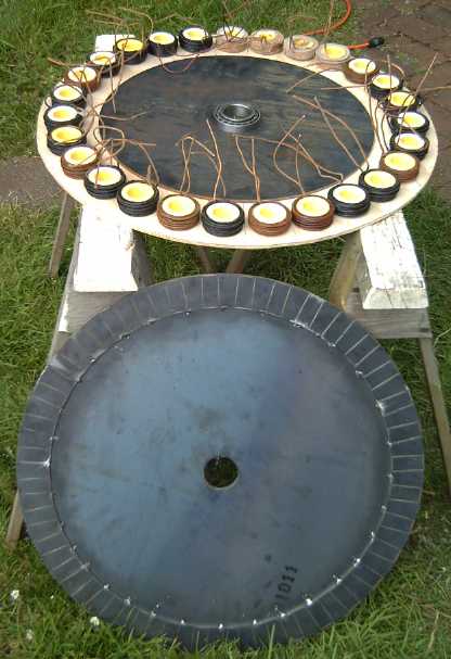
Pieces for the Weel motor.
I can't assign a very high
priority to this project until there are motor controllers to run it
with, and, being short of epoxy to do the rings the day I cut them, I
moved on to
other things.
Torque Converter
I started building a new torque converter before I
realized that a better motor controller had to come first. It had a
pivoting wedge piece to hit the drum to make torque hits, but I wasn't
entirely confident about the arrangement.
A mechanically inclined friend came over and talked about
centrifugal clutches. The converter couldn't grab on like a clutch, but
from that I got the idea of having the wedge spring out centrifugally
into a slot in the output drum rim rather than pivot into one. That
seems like it should have considerably more force, with both the
spring and its own inertial mass going for it, so I'm changing the
design and I'm calling it "most likely one to succeed".
Motorbike Project
Tristan's motorbike project seemed to be stalled. He now
had a job in Vancouver and hadn't made it to Victoria in months to work
on it. There was a prospect of him coming one weekend, and knowing his
time would be limited, I decided to put a few hours into it myself and
give it a jump start. I'd swap him his older version Electric Hubcap
motor that he'd made for the 'modern' one in the shop, which I fitted
onto the bike. Then I put an MC33033 board (working, at least!) into
his motor controller. Lastly I turned
down a motor axle to make a friction fit for the chain sprocket gear
and pounded it on, then I put that shaft into the motor.
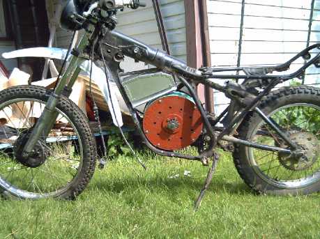 Motor (red) & controller (aluminum box) fitted on bike
Tristan was only able to
spend the day of Sunday the
19th, but we got it far enough along to try riding it. We found the
aforementioned low low-speed torque wouldn't get it going except
downslope.
 Tristan riding his "e-Bike" in the yard (slightly downslope).
3 Ni-MH 12 volt batteries were strapped on the back for 36 volts, but
the amps being drawn were quite low.
LED Lighting
In May I ordered three very bright LED "emitters" meant
for lighting.
They arrived. I made a 3 volt, 4 watt battery operated plastic dome
light
and a 9 volt, 4 watt
hallway globe light that I ran straight off a scrap 9 VDC, 450 mA power
adapter, plugged into a
light socket screw-in plug adapter in the globe light. 4 watts works
out to about 23¢ of electricity per month. The hallway is much
brighter than with the 7 watt CF light that was in there before. They
were about
as bright as 40 or 50 watt regular bulbs and were lovely white color
that I'll call "ultra bright moonlight". I decided I'll gradually
convert many of my house lights over and save
lots of electricity, and have ordered some more. Around 15 watts of
LEDs will probably replace a
100 watt bulb. (I've generally been using two 23 or 26 watt CF bulbs -
about 50 watts. One 23 watt CF seems considerably dimmer than a 100
watt
tungsten
bulb to me. So 15 watts is 1/3 of CF watts for equivalent brightness.)
At 15 or 20 $ per LED and needing two or
three for bright light areas, the initial cost starts to add up
- and with no satisfactory 120V LED installation system in place, so
does the installation
time. There are ready-made screw-in bulbs, which I'll also try out, but
from the sounds of things, they won't have the brightness or be as
satisfactory as the single emitters. There are also small triple
emitters I can try, which a friend is using for his solar panel + NiFe
battery DC power house lights.
Of course, once installed, LED lights may well last longer than me and
I'll never
have to buy or change bulbs again.
 4 watt LED globe light.
I like the diffuse light from the globe much better than small, intense
points of light.
Turquoise Battery
This month I decided to try Mn & Ni combo again for a
"+", with the same nickel "-" as last month's 2 volt vanadium-nickel
cell, and with the graphite-epoxy electrode glue as well as the "Diesel
Kleen" conductivity raising technique.
The electrodes seemed highly conductive, but cell
conductivity was still poor. I used
lots of graphite in the electrodes and in the glue, though I didn't use
enough Diesel Kleen on one of the electrodes.
I got another surprise: the cell was 1.5 volts instead
of 2 volts.
I was assuming the voltages were:
Ni/Mn+ ... Mn- 2.3 volts (+1, -1.3)?, but high self discharge
from the Mn- side)
V+ ... Ni- 2.1 volts (+1.1, -1)?
So this should have been +1, -1, but the total was apparently only 1.5.
Ni/Mn+ ... Ni- 1.5 volts
Either the Mn was only charging up to MnO2 (though it was
in fact made
with KMnO4, the higher charged state), or the nickel "-" side was only
-.5
volts... what I thought it should be prior to making the V-Ni cell. Did
that mean the vanadium was in fact +1.6 volts and the nickel -.5 ? ...
but if so, why did the vanadium seem to have no serious problems with
self discharge?
Near the end of the month, I started
experimenting with different electrolytes to reduce internal
resistance. Ammonium chloride didn't
help... how about organics?
I tried filling the cell with
toluene instead of water, and the case started cracking to pieces. A
whole corner fell right off! That was it at least until I have a new
case.
Wind Power Cost at parity with fossil fuels in 2010
Adding to the recent North Carolina report that in 2010
solar
power became cheaper (for new plants) than nuclear power, this from
Globalspec Newsletters: "According to the World
Wind Energy Association (WWEA), average installed wind power costs are
now on parity with fossil fuel plants." I don't know how this
compares with nuclear, but the report continues: In 2010, China
installed 19 GW of wind capacity, as did the rest of the world combined
for a total of
38 GW. (Compare with BC's Site C Dam at .9 GW.) Many of the largest
wind turbines are installed just offshore and the current plan - or
dream -
is to go from 120 meter
blade
diameters (5 MW) to 200 meters (20 MW). Offshore is safer and
the noise won't bother people. But I wonder if the requisite number of
windplants wouldn't cost less than the Site C dam and occupy less area
than that to be flooded?
I'm for it, but I must comment that if we're going
offshore around here, 20 MW windplants will surely be harder to make
than small, quiet 20 MW floating
wave power units that won't kill flying birds. The wave power units,
around Tofino, would also doubtless produce more energy per year.
Off-Topic Editorial Rant that really has no place here
I noted some very disturbing related things this month.
More and more we see those we elect to serve us passing
laws and
bylaws that curb individual rights and freedoms in one issue after
another. They wish to try to control and regiment people rather than to
empower them to make their own decisions and live their own lives as
they choose. It's become so prevalent that things that would have
brought storms of protest in past decades now pass without debate,
without much comment, and without any consideration of the overall
effects -- often just to solve one immediate small, perhaps emotional
or
popular, current issue. No attempt is made to educate to prevent
mistakes -- easier just to make something illegal!
As just one example, common chemicals I've wanted for
battery and solar cell development are unavailable or restricted simply
because (and this is just my best guess as to why, as no one seems to
have bothered even to explain the rationale to the public) the medical
profession thinks a few
people may be using them unwisely for health purposes, and wants to be
able to dictate
their medical usage. But making something illegal or unavailable
affects all its
potential uses, not just health. Problem substances include among other
things element #53,
iodine,
needed for electrolyte in DSSC solar cells, and potassium permanganate,
the best positive
battery electrode substance to give cells of the highest energy
density (used as a poultice). But there are more and more examples
of things restricting freedom to live one's own life besides substances
- you can think of
a few.
Now freedom of speech along with freedom of the press
appears to be under serious attack in the USA and
anywhere they touch. It seems any violent act or smear campaign against
any messenger who even might possibly bear unwelcome news is just fine.
The great bastion of freedom is moving towards police state as well as
bankruptcy.
First I watched a Swedish documentary on youtube.com, WikiLeaks
Rebels. In a featured "leak" was footage from a US military
helicopter
attacking and killing Reuters journalists on a street in Baghdad
from the air (2007?). Then, when Julian Osange, founder of WikiLeaks,
couldn't be
located (he's been forced to live at 'no fixed address' for his own
safety), he was
charged with rape of two women -
former girlfriends, neither of whom appeared to have initiated the
action, wanted to pursue it,
or were afraid of him - first to discredit his work by association, and
no doubt "hopefully" to get the Swedes to arrest him. This follows
another
recent multi-million dollar smear campaign I heard of
(though perhaps just a rumor?) by American drug companies to discredit
Michael Moore, who had done an unflattering documentary on the drug
industry. Before that I heard of a carefully prepared TV documentary
news report, an exposé on an unsafe Monsanto product being
injected into cattle everywhere, which didn't air because
Monsanto threatened
the network with suing them if they did. (This story too can be found
on youtube.) Instead the previously much
heralded "hard hitting news" stars who made the documentary ended up
sacked. Then in mid June I read a news report wherein a CIA agent said
someone from
the Bush presidential office had asked him to "dig up dirt - anything"
on
a university professor who was publishing to the web quite a different
view of the war in Iraq to that being put out by the White House, with
reports and footage from first-hand sources including Arabic. The agent
pointed out that it was illegal
for the CIA to spy on American citizens, and reported the incident to
his superiors. (Hurrah, integrity lives!) The White House
spokesman then
proceeded to find another CIA agent, and also made "improper" remarks
about the professor without any evidence whatsoever. The professor,
surprised, felt he was a pretty small fish to be gone after so hard...
what pressure must be on the bigger players? (Those involved were all
named in the news article, linked from a Lycos web search page, but I
didn't write the names down.)
The long and the short of it is, I suspect that killing
the
Reuters journalists (and several bystanders) was no mistake but cold
blooded,
calculated policy. Consider:
independent journalists would be likely to report things "out of line"
with Washington's "clean war" image (like that over 100,000 Iraqis were
killed) - just like the professor they went
after. The pilot first identified "RPG"s. Later
he called them "AK-47"s. The camera equipment became not just "looks
like weapons",
but specific weapons, which surely look little alike, and still
less like cameras. And no one on the ground was paying the slightest
attention to the prowling helicopter - hardly likely for combatants
openly
shouldering weapons on the street. Was the pilot that stupid? Then the
pilot urgently
demanded authority to fire
again on one of the journalists who wasn't dead and was painfully
dragging himself along the ground down the street. When a good
samaritan taking his kids
to (?)kindergarten stopped to help and took the wounded man into his
van, the van
was shot, killing the man as well as the journalist. (The children
miraculously survived. They will probably not think of America very
fondly.) This would make no sense either: a badly wounded soldier is no
threat, and shooting a rescue vehicle is everywhere considered
reprehensible. A wounded journalist, on the other hand, if he lives
will write a terrible story for public consumption: he is even more
dangerous and must be
finished off.
With all that, I strongly suspect the pilots had orders, from the top,
to shoot "unauthorized" journalists, and to report cameras as "weapons"
in case
their transmissions were overheard. The White House "demanded" that
WikiLeaks.org return all the vast evidence of their crimes against
humanity. (The whistleblower was a brave young intelligence officer who
will probably pay a very heavy price.) They got just the unwanted
publicity they were trying to stifle by force. The world needs an
international police force, not a
bullying nation operating in defiance of law and decency and without
the sanction of the international community, for its own ends.
American democracy (not to mention Canadian) is proving
unable to evolve as needed to continue its serviceability to a free
society - only ineffectual if not actively corrupt people seem able to
win
election, shutting out those truly fit to lead. Most emphatically, the
"illiterate's X" voting system, which has never worked right, needs to
be replaced with choice ranking. Australia and New Zealand have it -
and probably most of the civilized universe. And Canada needs to let
the people elect their PMs and Premiers, just as we elect our mayors -
not allow them to be picked by the largest partisan faction ("party")
in the legislature.
The two mistakes give rise to a partisan
faction ("party") controlled system where 'the leader' has all the
power. Canada in particular comes closest to electing a dictator of any
nation. Such "party" systems are open to corruption by rich
vested interests. Decisions on public matters are made privately behind
closed doors -
mainly by the leader of the largest faction - and "rubber stamped" in
the deliberative houses where they are supposed to be openly proposed
by members,
discussed and decided on. In April's federal election, while others had
signs
supporting individual candidates, I made my own political comments
along these lines:


I thought this could be educational not only for what was
said but simply because most North Americans have never even seen a
choice ranking ("STV") ballot. Ideas are scary for being unfamiliar
when
being discussed.
A photo taken from a back row seat inside the US senate
during a recent session showed the 'minority leader' speaking, while
two senators ahead were playing cards on their computers, another was
on
Facebook, and a fourth was doing something else unrelated (texting?),
accounting for all the people nearby in the view. My own member of
Parliament Dr. Keith Martin - who was one of Parliament's
leading movers and speakers - finally threw in the towel in
frustration in the last election, saying the system is so dysfunctional
no one can accomplish anything. Apparently many if not most of the
people
we elect to serve us and improve civilization feel just about as
powerless as the rest of us.

Quoting
from a greater American statesman than those seen recently: "Those who
make peaceful evolution impossible make violent revolution inevitable."
- JFK.
I trust it won't come to that. Change begins with each
individual. Individuals are changed by faith in the first source and
center of infinity - the Universal Father, trust that the universe is
friendly, in recognition of the human family ("We all breathe the same
air." - JFK again), and by
education. The internet is helping people - presumably including future
leaders - learn, by providing open access to previously
obscure (or deliberately hidden) documents and materials, and providing
many previously unthought-of solutions, of which WikiLeaks and
OpenLeaks are just one example type. You can think of more. And the
improving communication is bringing our extended human family together,
as never before.
Electric Hubcap Motor System
I got serious about motor controllers this month. After
trying to get the A3938 controllers to work early in the month without
success, I put together some MC33033 controllers. Tristan came over and
we assembled his "electric hubcap" motorbike far enough to try and ride
it. It wouldn't move except downslope, and it was only after a week and
a
dozen blown MOSFETs that I got it to move along level ground...
and then another MOSFET blew. So, much of the month was unexpectedly
converted to motor controller trials and tribulations, and the MC33033
(as built) proved much more troublesome than expected. I think (maybe)
that over about 24 volts the spikes are making the MC33033 'huccup' and
leave on for too long MOSFETs that are supposed to be off. It doesn't
help that it leaves half of them on regardless of PWM.
Before the end of the month, I finally realized I could
ditch the motor controller chips entirely and use... an LM339 quad
voltage comparator (timings, modulations and on/off gating) and a 4070
quad XOR gate (forward/reverse), with 3 'beefier' half-bridge MOSFET
gate drivers than the present MC33033 board has. Yes, worked down to
essentials, that seemed to be all a brushless motor controller really
needs, and it would give the "current ramp" type of modulation I wanted
from the A3938. On detailed considerations, the IR2130 triple MOSFET
driver seemed like the best choice of drivers, and I could use its
internal op-amp (with a couple of seemingly unrelated pins) and drop
the LM339. On the IRF.com website I found that's been superseded by a
new "IR2133", which, with some creative fanagalling, can do the job
with just one other chip. (the quad XOR gate) So after a long run since
spring 2009 I've come right
around the loop from several general purpose chips to dedicated motor
controller chips and back pretty much to my original chips -- but fewer
of
them, to make a better motor controller.
The very long subsections on motor controllers written
below, something of a 'diary' of events as they unfolded, give
'blow-by-blow' details
of all this. Unless you're really into motor controllers, it's probably
a
good section to skip.
The End of the A3938 Motor Controller?
The
control method of the A3938, ending
with a short fixed "off" period after a variable "on" period while the
coil current "ramps up" to the set current level,
may (possibly) be called "direct torque control" (DTC), "delta
modulation", "delta-sigma modulation", or "chopper control". None of
them seemed exactly
applicable. (See Wikipedia "PWM"
article.) I prefer to call it "current ramp control".
I decided that if I blew
the last A3938 chip, I'd go back
to the MC33033 controllers until some future time. It developed that
the
"is being discontinued" notice only applied to
the DIP package of
the MC33033 (the one I was using), not the chip as a whole. Other
packages remain available,
so
the circuit board would just need a little redesign. I'm glad the DIP
version was there while I was troubleshooting the prototypes! Much of
the trouble and time spent trying to get the A3938 to work has resulted
from the miniscule
packages, that are hard to place and solder and can't be socketed.
I disconnected one pair of transistors from each motor
drive output: Vbb, the output node, and the gates. This was intended to
reduce the load on the A3938 gate drives from 200+ nano Coulombs to
100+ nC per the recently discovered "app note". In all the crowded
wiring I was nervous about doing this, but
I checked everything I could think of and taped off bare wires. What
could go rong?
I turned on the power and turned on the switch. I turned
the motor a bit by hand and BLAM! Two mosfets and the 30
amp fuse were blown. But as I disassembled things I found out why: the
voltage
sense from one of the outputs to the board was soldered to the
disconnected mosfets, so the voltage sense reading for that output was
invalid.
By this time I had removed the six drivers that were in
use, so I reconnected the other six and rewired everything. Evidently
the chip somehow wasn't blown in the carnage. However, the motor still
wasn't getting power. Evidently it wasn't the gate drive timing delays
that were
the problem... so now I knew to look elsewhere.
After getting some shoot-through currents, I had set the
dead time between turn OFF of one mosfet and turn ON of another to the
max, about 5 microseconds. On the oscilloscope I was seeing voltage
spikes
under 1 uSec, so I decided to try some compromise value.
First, to limit potential damage, I put in three 1 ohm
resistors in series with the
three motor leeds to limit the current, and another 1/2 ohm in series
with
the main power.
I tried 100 K ohms, which should reduce dead time to about
2
uSec.
That didn't seem to help either. But on the scope I could now (finally)
see a steady high level voltage on one of the motor supply wires. How
could motor wires be high and low, and yet the motor still drew no
current?
I looked at the plug on the motor. I had made up a special
test plug last month with thin (#18) wires - again to limit
destructive current for
testing - and my memory is of carefully making sure the pins had
clicked
home into the sockets, but there it was: a pin not properly inserted,
and apparently not making a connection.
With that fixed, the motor slowly turned. It was working!
Very soon I
could smell hot resistors. It turned both directions, which meant that
by considerable luck I probably had all three phase wires right. I
removed the 1/2 ohm resistor from the power and tried again. The motor
turned a little faster. My hand came near one of the one ohm
resistors, and I could feel the heat, without even touching it.
Obviously most of the power was being used heating them up instead of
turning the motor.
I removed the resistors. When I reconnected the power I
thought I
heard a "snap" noise from the circuit board. The power voltages from
the chip
indicated it was fried, evidently without even trying to run the motor
(I tried anyway, to no avail). No evident rhyme nor reason. That was
June 6th.
That pretty much did it. I really hate to give up on a controller chip
from which much was hoped, after so much investment of time and money,
and that was running motors pretty well last fall when first tried. I
finally remembered why I couldn't even duplicate those results: the
initial time when it worked, the motor coils were connected with skinny
alligator clip leeds (and so was the power IIRC). Those were something
like the current limiting
resistors, and I'm not sure it ever worked once wired "properly".
Since it worked with resistance in the lines
and not without it, perhaps I should try putting some resistances or
RC filters in
series with the output voltage sense inputs to the chip to limit
current?
(The app note boasts about how the high voltage section was implemented
with a minimum of silicon - who cares? That means nothing beside
reliable operation. The MC33033 boasts of "industrial ruggedness".)
Another thing I noticed after I switched back to the
MC33033 is that Motorola used an RC filter on the current sense line
(which
I duly copied) while the same raw, spikey current signal connects
straight to the A3938 in Allegro's drawings. I did it their way without
giving it any thought, but that line is certainly a potential source of
chip-blowing transient voltages. Perhaps all four lines coming back
from the motor coils to the A3938 should be filtered.
Filtering the lines to reduce spikes to the chip might
make it work. I may (or
may not) get a few more A3938s for the 5 PC boards I already have. Or
that might just save the chip and blow MOSFETs instead because of
slower voltage sensing times!
Mid-month I started thinking of using a microcontroller,
which can
implement similar control plus regenerative braking - and anything else
I can think of.
A Revised MC33033 Motor
Controller?
After my last A3938 chip failed I
put together a couple more MC33033 controllers just to have some
working controllers, and for a while
considered trying to "trick" them into doing the A3938's "short fixed
off
period" with a bit of additional hardware. Then I decided to just raise
the PWM frequency a lot.
The "current ramp" control
technique of the A3938 is preferable for car drives. It's got superior
low speed torque, lower power dissipation (less heat in the
transistors), and a more familiar "gas pedal" control feel. But in
the time
I've spent troubleshooting I could have put together a few working
controllers of the old type. A controller for
the shop was certainly needed now, and one for Tristan's bike, the big
Weel motor will need three
more by
itself, and to be able to offer reliable controllers known to work with
the
Hubcap motors would doubtless be a big asset for selling them.
"Optimized" controllers would be even better.
The big asset to the MC33033 controllers with the 3
separate IRS2003 half bridge MOSFET drivers was that I
thought I had them working well.
The biggest problem with them is that the main control and
the current limiting control are separate. When the motor is stopped or
turning
slowly, the current will rise quickly. When the maximum current is hit,
the PWM cycle shuts off to avoid exceeding it. But the
cycle is no shorter, so at low speed the motor spends most of each
cycle turned off,
being supplied a low average current overall. Unless the
oscillator frequency is set very high (which brings in needless
switching losses and heat in the controller at all times) this
limits bottom end torque, right where torque is needed most to get a
vehicle to start rolling. This has doubtless been a factor in my torque
converter failures, especially the last 'clock escapement' ones. In
fact, in 2008 with my original multi-chip controller, the car moved
across level pavement, however sluggishly, with the motor tied
directly to the wheel.
That feat hasn't been repeated since making the
MC33033 controllers, presumably because of the low low-speed torque.
And I suspect commercial
controllers use this - "the usual" - PWM type control. This
may help
explain why some bigger motors or higher gear reductions are being used
in
electric conversions than seems to me should be necessary.
Tricking the MC33033 to do "current ramp" control?
But could this unsatisfactory control be modified somehow
on the MC33033 chip?
The signal that says "the MOTOR ON part of the cycle is terminated" is
unfortunately
internal only, but this
condition is indicated if all three low drive signals are off while
running. With a 3
input CMOS (15 volt) NOR gate, a high "MOTOR Power OFF" signal could be
generated. But once again, there's no external input to make the
desired use of that signal. But it could be tied through a diode and a
resistor to
the RC (ramp oscillator) pin. The resistor would be much smaller than
the regular oscillator pull-up resistor, which would cause the RC pin
to rise
quickly to the trigger threshold, rapidly (but not instantly)
terminating the cycle once the motor had shut off, regardless of
whether it shut off by PWM signal or overcurrent signal. The "short
fixed OFF time" of the A3938 would become a "short variable OFF time"
in the
MC33033. The operation would become more akin, and varying the resistor
would allow a range of characteristics.
There's also a similar MC33035 with 24 pins instead of 20,
but on
checking it, it didn't seem like any of the extra signals would be of
much use for implementing the changed operation.
Assembling Controllers
On the 8th I got out an MC33033 controller board, which,
when all wired up turned out to be the blown one (yes, I should have
labelled it "blown" back when it blew), then the other one, which was
rather hacked and
took a while to put into shape. But within 2 or 3 hours I had it
running a motor. (46 W at 500, and 93 W at 1000, no-load
RPM.) I didn't try anything beyond basic operation.
In the afternoon I got out a brand new MC33033 board and
soldered all the components on. (I had to scrounge a couple off old
boards to avoid a shopping trip or (worse) waiting for parts - seems
I'm always out of something!) I
hooked it to the power drivers for Tristan's Bike (a project much
delayed since he's got a job in Port Alberni & Vancouver). By the
end of the day it
was ready to test and, if good, to run.
In this one I bent up the "enable" pin (Hah! Try that with
surface mount components!) and added a resistor and transistor in
series with it to make the external pin "*enable", active low. (That
way the motor will be OFF instead of ON if the operator controls plug
isn't
connected - planned for all future
versions.)
The next morning I tried it out. It worked great. ...from
1 working controller to 3 in a day.
This time, the same motor
seemed to start turning more snappily, and it read about 35 W at 500
RPM
and 78 W at 1000 RPM, no-load. Not bad for a 5000+ watt motor, but
evidently the power needed had quite a bit to do with the controller
driving it. Perhaps it could be even better!
What was the difference? I found that the first controller
had had a 6x larger
oscillator capacitor installed, lowering its PWM oscillator frequency
proportionately. It shows what a difference can be made: if it
had had the "short OFF time" to terminate the cycle after the power was
cut, it should have worked as well as the higher frequency, perhaps
even better - and indeed
it would have been running at a higher frequency under these no-load
conditions - but retaining the much reduced switching rates when high
speed, high
power was being asked for. Even if nothing else, this would reduce the
heat in the controller when it was delivering high power. I
switched it to the smaller capacitor (which also soon proved to be too
big, in the first motorbike test).
Microcontroller Based Motor Controller
Not to go way off on a tangent, as I thought about it
towards the middle of the month, it seemed to me the A3938's problems
were mainly with current and voltage spikes. The MC33033 only gets one
of the problem signals itself, and specifies that it be filtered. The
IRS2003 half bridge drivers seem to handle the rest of the nasty stuff
well - it's their only job. So the key to reliable operation isn't
really the MC33033, it's the little IRS2003's. At the same time, there
were some problems and question marks cropping up in designing circuits
to trick the MC33033 into operating a little differently.
So perhaps it would be preferable to use a microcontroller
chip. Then the control scheme, its adjustments and
timings, and many other features, could be exactly as desired and
tweaked in the software. Including regenerative braking, all
implemented
exactly as I like it best. Plus, any number of "dumb" statuses and
analog signals could be reduced to a 3- or 4-pin serial interface on
the
controls plug/cable to the dash (eliminating the third header
connector, and a second cable to the dash), and the controller could
warn
of motor overheating (even reduce max. power itself), etc. The IRS2003
driver parts of the PCB, and the heatsink assembly and mosfets, could
remain the same.
Though it's rather vexatious to start from somewhere near
scratch (though far better armed with solid experience and knowledge)
and with the need to write some exacting
control software, I decided this
would be the ideal way to go. I selected an ARM RISC chip, the
SAM7S16. This might be thought "overkill" in processing power, but it
should be easier to
program in assembly language than some low performance CPU, and it's
still just 6 $.
This would mean not only a motor controller matched to the
Electric Hubcap motors, but a truly superior, "ideal" controller that
will squeeze maximum performance out of a motor at all RPMs, and
maximum range out of the batteries. I wasn't, however, looking forward
to all the study and work.
MC33033 Controller Again (yikes!)
On yet further reflection, I decided something working was
needed soonest, and the only obvious way to get working controllers
soon was to use the MC33033, or the A3938 if it could be tweaked into
working. The MC33033 at least worked, now, and evidently just needed a
circuit board revision because the DIP size chip is no longer
available.
Raising the frequency would give it more low end torque, "workaround"
solution or not.
On the 20th I raised the bike controller's
frequency up about 15x to the "recommended" 25 KHz, and
the controller promptly burned out just as the bike wheel started
turning. That's why I hate experimenting with the controllers
-- if it's working at all, leave well enough alone! Evidently there was
still
a problem with the controller after all, which only became troublesome
at high PWM frequency.
Just two mosfets were blown and I soon had the controller
fixed. But what was the problem?
Was the filter on the current sense line too well
filtered, and sensing of the currents too delayed? I changed the .1 uF
filter to .022 uF, and put in a current sense "resistor" (thinner wire)
that should cause it to trip off at around 30 amps. It seemed to work
well at the high frequency at 24 volts, with currents around 20-25
amps, occasionally 30 and a 40 and once 60 amps reading. That 20-25
amps at 24 volts also seemed to be just enough 'juice' to propel the
bike at a walking pace with no one on it. To ride it (besides
downslope), higher current or higher voltage was needed.
But currents went wild at 36 volts. On the bike with the
current probe attached and the meter bungied to the handlebars I saw
80, 160 and 140 amps flash by, instead of 20-30. There, then, was the
trouble causing the blowouts.
There was the familiar cracking sound, and then another
before I could pull the battery jumper leed off. (No breaker-switch
yet.) The
ultra-reliable 40 amp fuse remained in perfect shape throughout.
(Thanks a lot!) But this one time, the cracking sounds had come from
behind, at the batteries, and it turned out nothing was wrong with the
controller.
I put the .1 uF filter capacitor back in, and at 24 volts
everything was still fine. I got out the 5 volt battery, and at 29
volts, the currents went wild again. If the cause can be determined and
fixed, I think there's controllers that will work acceptably, otherwise
not.
But what was the trouble? Switching shoot-through currents
come to mind - they're not amenable to being controlled, and MOSFET
turn-off time probably increases with voltage. At the lower PWM
frequencies, shoot-through current might be occurring -- but so much
less frequently it makes little heat and does no damage. The IRS2003
has a fixed dead time of 1/2 a microsecond. It seems to me I had to set
the dead time higher than that on the A3938 to eliminate shoot-through
currents. What could be done with a fixed time chip? One technique
that's been used is to put an ultra-fast diode in parallel with the
gate resistor to speed up turn off. But that effect will be minor.
Rechecking its specs, I discovered (rediscovered) that the fixed dead
time of the IR2130 triple MOS gate driver that I used in my original
controller was 2.5 uSec - 5 times longer! Here, then was a big
difference... IF that's what the problem was.
One thing I thought of to help prevent damage during
tests: limit the current by using a single bank of NiMH "D" cells in
series, whatever the voltage. They're rated for 30 amps continuous or
50 amps intermittent, and the voltage drops off rapidly above 70 or 80
amps. This is a good current capacity range for the tests, though the
1200 uF of supply filter capacitors will supply more for brief periods.
I made the battery pack, but it gave me the thought that
perhaps the filter capacitors were insufficient. The rapid switching
might confuse the current probe? Maybe there were no real very high
currents? After all, the 40 and then 30 amp fuses hadn't blown.
I found some 470uF, 200V caps and put in about 1400uF
instead of 1200. (I had to remove some of the 100uFs to fit the 470s.)
Blam! More transistors blew. This time they took out the 30 amp fuse.
So much for "the currents weren't real."
Causes of the problems?
Problem 1 - A3938 Controller: transient voltage rating
Most chip inputs don't want to see voltages much above the
supply or below ground. I knew special precautions were taken for the
motor power signals - IR's half bridges were all "negative transient
tolerant". But the A3938's "absolute maximum" for negative voltage
coming in from the motor phases was only -5 volts... and I found no
mention of spike tolerance. The spikes are 10 to 12 volts. Ouch --
negative 12 volt spikes might well be
what was blowing the A3938s! The belatedly found app notes spoke of
motors only "up to 1 HP".
Problem 2 - IRS2003 half bridge: too short fixed dead times?
Possible the .5 uSec fixed dead time is too short -
at least with the long switching times enforced by their low gate drive
current. One could wish these had the 2.5 uSec of the IR2130, but ALL
IR's many 8 pin half bridges have a similar .5 uSec fixed dead time -
maddening! Shoot-through currents could be why MOSFETs keep on
blowing. At low PWM frequency, the MOSFETs could recover, but at high
frequency, they overheat fast. (I wish I had a spare motor for bench
tests. That should be the next project. I have the parts and it would
only take a day or two.)
I'll have to go to the 14 pin drivers with resistor
programmable dead times.
Counting the resistor, that's double the connections, 16
wires instead of 8! Or I could go back to the 28 pin IR2130 triple MOS
driver. But that chip has separate high and low inputs, and no "output
enable". Two extra logic chips are needed to recombine the inputs and
to
allow modulation, so it saves nothing.
Problem 3 - MC33033: Low drivers stay turned "on".
The MC33033 only modulates the 'high' side drivers: the
'low'
side (as I use them) stays on. That's
okay if everything is fine, but it'll cause extra trouble if there's a
problem. I started thinking about using an external modulation. If the
MC33033 "output enable" was used to accommodate an external modulation
signal, as well as gating on/off (with the PWM voltage held high and
ignoring the MC33033's PWM), it would turn both high and low drivers on
and off. And with external modulation, by LM339 or whatever, it could
run
the
way the A3938's does, with variable current limiting and a short fixed
off period.
Hmm... was the MC33033 even needed for such a system? Some
models of half bridges could perhaps be modulated directly. Ah, the
vast array of possibilities!
Simplify, simplify, simplify!
By June 25/26 I thought a big part of the
key
is in the 3 half-bridge MOS gate drivers. I'd get the type
with one input for high/low select, and
another for "shutdown" (SD), AKA "output enable" or "on/off".
For the simplest brushless motor controller: connect the
hall sensor directly to "in" for each phase, and a modulator to "SD"
of
all three, through an "on/off" switch. The simplest modulator is a 555
timer for a PWM generator. Total chips: one 555 and three half bridges.
Or instead of PWM, one could use an LM339 quad comparator
and use it to do "current ramp" modulation, which compares the current
against the reference voltage from the control. (I haven't worked out a
specific circuit, but I'm pretty sure the LM339 has it in it
somewhere.) Total chips: one LM339 and three half-bridges. This also
(inherently) protects the motor and transistors
against overcurrent to the motor, like the A3938. This is complete: one
comparator does the current sensing, one does the fixed "off" time, and
one interfaces the "on/off" switch.
Those were getting really simple! Unfortunately, I
overlooked that there's a band where they are supposed to be "off".
More inputs are needed to accommodate that. Again unfortunately, the
IR2110 has the required inputs -- but latches the SD input so
the drive
can be turned off, but it can't be turned on again until the motor has
rotated to the next position -- which it won't do as it has no power
because SD is latched off. All these clever ways to make chips
that don't quite work!
IR2130 (IR2133) Motor Controller - back to 2008!
I finally decided that the best solution (of several
unsatisfactory choices) would be to use the IR2130 triple gate driver
(2.5 uSec fixed dead time - 5 times longer) and some "standard" logic
and interface
chips -- about the same as I'd been using before I ever heard of the
MC33033 or other single chip brushless motor controller chips! This
time however, I would make it with 'current ramp' control. It seemed it
could be
done with 4 chips, counting the IR2130.
Then I looked closely at the IR2130's internal current amp
and overcurrent shutdown. It occurred to me that since a triple
external gate was already needed anyway, I could 'trick' the
overcurrent shutdown into unlatching. Furthermore, the current amp
could be used to compare the control ('gas pedal') pot with the
current, eliminating the need for the LM339. Also there
was a built-in 9 uSec delay turning back on after overcurrent: the
"short fixed off period", built right in! Now the IR2130 controller
could
be made with just 3 chips: the IR2130, a 4011 quad NAND gate and a 4070
quad XOR gate. (If the motor didn't need to reverse, just the IR2130
and the NAND gate - 2 chips!)
On the 29th I check at IRF.com, and found that the IR2130
has been replaced by a new chip, the IR2133. It had a "FaultClear"
input and a
"ShutDown" input. Together these allowed elimination of the 4011 quad
"NAND" gate (or 4071 quad "AND" gate), reducing the chip count to just
one
IR2133 and one 4070.
The IR2130 (or else 3 half-bridges) would be needed even for a
microcontroller "solution",
so that would be 2 chips, and the microcontroller would have many more
pins than the 4070. Overall the circuit complexity would be about
the same or a bit more complex -- and it would have to be programmed.
The advanced but non-essential features that the
microcontroller could bring can wait. I think simple
logic dictates
that simple logic is the best way to get controllers working
ASAP, and it'll have the main feature: the good current ramp control.
...all assuming I can get them to work well however it's done!
Motor System Thinness
When I see the motor on the car, I realize that the less
it sticks out from the wheel, the more acceptable it'll be. When the
first version moved the car with the motor rotor bolted directly to the
car wheel, it was quite short. Now, a "regular" configuration motor, a
torque
converter, and a flexible coupling to the wheel, each add their bit of
width. As I measure the pieces of the present motor with the disk brake
type magnet rotor and the torque converter rotors, it's about 7". With
the
flat rotors, that'll reduce to 6".
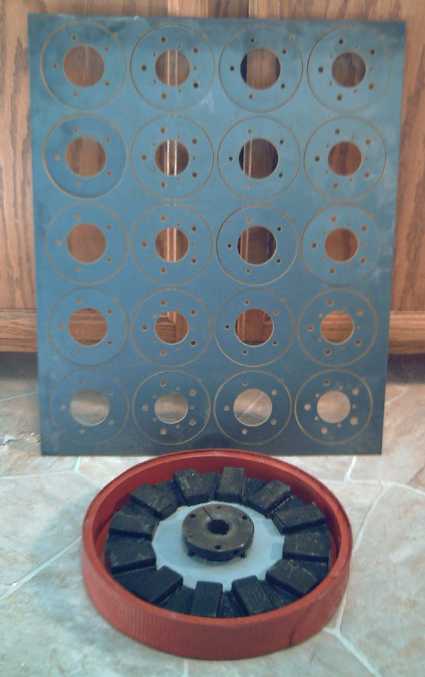 Top: CNC waterjet cut bearing holders for the ends of the motors,
each held to the plate by a thin tab.
Top: CNC waterjet cut bearing holders for the ends of the motors,
each held to the plate by a thin tab.
Below: new flat plate magnet rotor, in a thin composite motor rotor
compartment shell.
(The gray color of the steel rotor plate is polyester powder coating.)
Some bolt heads stick out. If I switch the ones on the
shaft side of both the motor and the torque converter input rotor to
flat-head bolts, the torque converter rotor (an inch thick) can be
almost touching the motor body, saving about 3/8" - so 5-5/8". I think
that'll make it protrude less than than the right side rear view mirror.
Beyond that, there's making the walls and pieces thinner,
but this is probably inadvisable and for small returns.
Here we see an advantage to my previous design with both
shaft bearings on the stator, no inside side wall, and the
motor rotor doubling as the torque converter input rotor: it saves
around an inch of thickness. But the end of the motor has to be open.
The shaft of the enclosed motor is
mechanically stiffer with the greater distance between the bearings. A
combo configuration remains an option, but is probably best avoided
without a
finished torque converter design. Once there is one, the idea can be
re-examined, again using the magnet rotor as the inner torque converter
element.
A possibility for an enclosed motor-converter would be a
concentric axle system: a hollow pipe torque converter output shaft
would surround the motor shaft at the wheel end. All the components
would be enclosed and only the output shaft (with a wheel lug-nut drive
plate
attached) would appear outside. The motor casing would be thicker by
the width of the converter drum.
One other possibility for a small reduction is to use
thinner supermagnets: 3/8" instead of 1/2". The 1/2" ones are more than
strong enough, and the flux gap is also over 1/2". The steel magnet
rotor thickness might well be reduced from 5/16" to 1/4". If using 3/8"
magnets also reduced the best flux gaps by 1/8", total width savings
would be about 5/16" -- and presumably the the supermagnets would cost
less (and there'd be some reduction in their potential to do damage or
injury during handling). But it may be found that the lesser depth of
field of the thinner magnets reduces motor performance. In that case,
thinner magnets might be better matched to thinner coils, eg 3/4"
instead of 1". That would save even more width, but the whole motor
would be less powerful.
I have high grade (N42) 3/8" magnets and the thinner
rotor, and will
give it a try when I have time, comparing one motor's performance with
the two different rotors installed. (However, so far I haven't even
done complete tests on even one motor since improving them! I still
need some sort of mechanical motor test load.)
Lower Power "Electric Hubcap" Motors?
The above thoughts on thinner magnets bring the idea of a
lower powered motor of the same design with the same ~95% efficiency,
with thinner coils and magnets. For example: 1/2 inch thick coil cores,
1/4" thick supermagnets, for a 2.5 KW motor, still 2000 RPM. Everything
including
the body parts would be a little thinner (use less PP & epoxy
each), making a motor of the same diameter but only perhaps 2.25 to
2.5" thick instead of 3.5".
These wouldn't be for cars, but eg for bicycles and
cordless lawnmowers. For a mower, 2.5 KW is still considerably more
power than can be had from a 120 V, 15 A house circuit (120 V * 12.5 A
= 1.5 KW). The 1.5 KW mowers are generally underpowered for tall or
damp
grass. 2.5 KW, with higher efficiency, should make the difference, and
the low voltage (and no cord) eliminates shock hazard. (Now, just need
those better batteries...)
Much as I'd like to try out this mower (with some NiMH
batteries?), I'd need to order the thinner magnets and coil cores, and
I don't know when I'd find time to build it. And it wouldn't cost a
whole lot less than the 5 KW version.
Another option would be to use six 'regular' coils and
eight 'regular' magnets, and make a smaller diameter, 3000 RPM, 3.3 KW
motor. But then new molds for the PP-epoxy body parts would be needed,
so that would take even more setting up.
Such motors would be pretty simple to develop at this
point and might be very useful, but would be just one more
sideline from the main project, hybridizing cars.
Metal Protection
Protecting the steel of the magnet rotors and bearing
holders having entered my thoughts, and the powder coating being very
nice but too costly, I
looked around for a good alternative. I thought perhaps there might be
a spray of two-part thermosetting epoxy that could be simply sprayed
on,
and then set in an oven, essentially working much like the dry powder
type.
Instead, at Industrial Plastics, I found a spray can of
"Cold Galvanizing Compound", "97% zinc". Evidently with "ketone
peroxide" (MEKP?) in the spray, the zinc powder "bonds with the steel"
to form a
galvanized coating. As a plus, even if it's scratched, the nearby zinc
becomes a 'sacrificial anode' and prevents the steel from rusting, or
at least, prevents the rust from spreading underneath the coating. This
sounded
like a reliable bond and about the best possible protection. The guy at
the powder coating
place had mentioned zinc as being their primer coat, too.
I had been impressed by the prep steps for the powder
coating.
There's degreasing and then cleaning the metal to a shine before
coating. I degreased a flat magnet rotor by heating the surface
with the hot propane torch. I thought it was pretty clean to start
with, but one side in particular seemed to become wet everywhere as it
was heated, and this would finally boil off. Not much happened on the
other side, though a few small patches changed color a bit.
I thought it would be a snap to shine up the metal after
that with a portable belt sander, but it took two belts (they broke
after a while) to do one side. There was some blue-beigey color coated
on
it
that was very difficult to get rid of. Considering it didn't come off
with the torching, I'm wondering if it was some sort of metallic
coating already, and if perhaps removing it is pointless. I decided
that was probably the case and finally sprayed the other "un-silvered"
side too, and then a pair of bearing holder pieces, but I plan to ask
at a metal shop.
The zinc finish looked rather rough and not uniform - like
it was formed from powder and sprayed by hand - but
good.
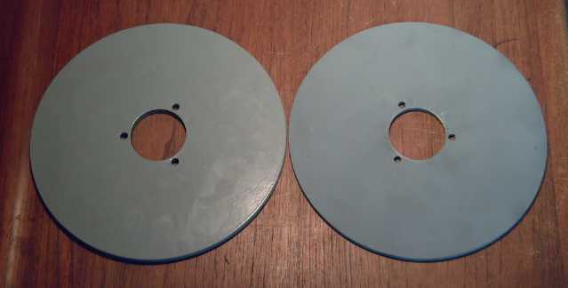 Two rotors:
(L) powder coated polyester, (R) "cold galvanizing compound" (zinc
powder) spray can.
Two rotors:
(L) powder coated polyester, (R) "cold galvanizing compound" (zinc
powder) spray can.
A couple of spots have scratched off on some bearing
holder "washers". I'm thinking of trying out some sort of heat
treatment to fuse the zinc to the steel better - oven, kiln, torch --
?
Thinner Motor with Flat Magnet Rotor
I gave the motor in the shop over to the motorbike
project, so I needed a new one to continue the torque converter
project. Now that I have the flat magnet rotors, the obvious thing to
do was to put a motor together with one, making one of the planned 3.5"
thinnest motors that I'd already molded two bodies for. I had all the
other parts except one bearing holder set, and assembled motor coils
that were handy, removed as a group from an open format motor. This was
the "first try" set with the rutile instead of the superior ilmenite.
As the sodium silicate was unbaked, I could easily wash the rutile off
and
redo it with ilmenite. This time I'd try sanding the wire a bit to
roughen things up, as the rutile was flaking off badly. Five sets of
bearing
holders were on order at Victoria Waterjet. It boiled down to putting
together the magnet rotor. I did that on the 16th, and the same day
the bearing holders - 10 sets - were ready.
I lightly sanded the magnet side of the polyester powder coated rotor.
It was very smooth and I was just slightly nervous about how the epoxy
would adhere. I think it would have been fine. (Pictures of this rotor
finished and unfinished are above.)
Then I got into motor controllers again and didn't finish
making this motor. It's mostly done and won't take long now. When the
rutile
coil coatings are replaced with ilmenite, it can be
assembled.
Electric Weel Motor
I wasn't looking forward to making a mold for the 27.5"
stator rings for this huge motor, or to the epoxying job to fill that
mold.
And the 27-1/2" ring wouldn't fit in the oven to rapidly set the epoxy
like the
smaller ones. Then I had the idea - at least for the prototype - of
cutting the rings out of 1/4" plywood, and then simply painting on a
couple of layers of polypropylene fabric with epoxy resin to stiffen
it. Since it was
just 5" wide rings fastened to a metal center, that should be strong
enough. I calculated the two rings could just be made from 1/2 a sheet
of plywood (4' x 4'). That worked, however the 1/2 sheet of plywood
cost
only a little less than a full sheet at Rona.
That just left the rotor end wall. That was going to need
more strength, so I might just make it of 1/2" or 3/4"
plywood, again PP-epoxy coated. (Although, being behind the magnet
rotor rather than in front, it could probably be made of metal without
causing drag. Wood or composite will be lighter.)
I'm not sure this can be made under 100 pounds as I hope:
the 27 coils alone weigh almost 25 pounds.
Weel Motor pieces:
- Stator" 18" steel plate with 17" - 27.5" plywood outer ring (a 2nd
ring
goes over the 27 coils)
- 26" rotor, 2 pieces tack welded together, with magnet positions were
layed
out by the CNC waterjet.
Torque Converter Project
I dropped by a recycling place and found a sheet of 1/8"
aluminum for the two input rotor pieces, and perhaps
for the outer rim of an output rotor. I cut them out with a jig saw,
~11.4" diameter, then fitted them to the SDS coupling. Everything was
rough hand
work because they
were too big for the lathe.
(Again I need that pulsejet cutter that I didn't finish making, fitted
to the CNC machine!)
I cut some
5/8" thick pieces to bolt across
between the two, making the rotor 7/8" thick. The center holes were
sized to fit it onto an SDS bushing, which would compress onto the
motor axle.
I thought the plastic pivoting wedge pieces I'd cut were
about the right size for the first try, but that the pivot hole should
be a little higher up. On the 15th I redid them, this time in aluminum.
I then decided I'd put just one on, and cut one square "slot" in the
output drum, and see how that worked.
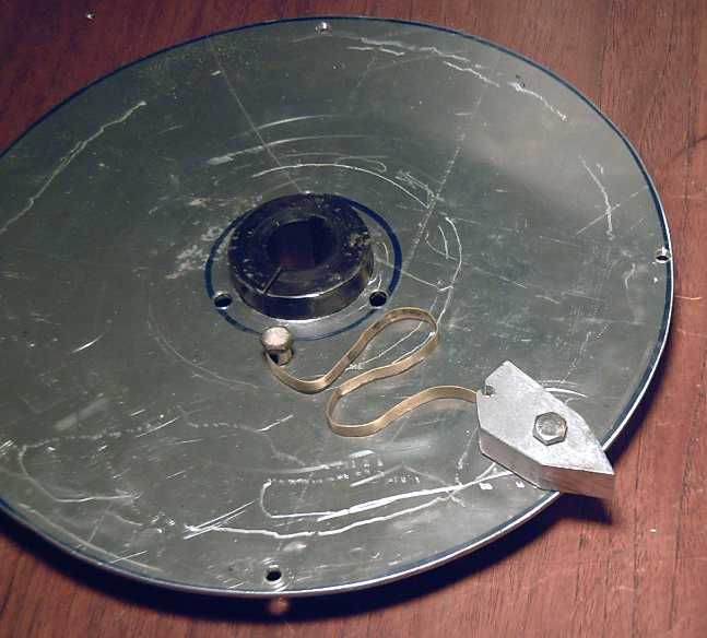
Wedge with spring on input rotor (shown on single disk of double rotor).
The snakey tempered brass spring is much stiffer than you might expect.
(Say... perhaps it should be redone as a spiral coil - the traditional
spring shape.)
A complication arose when
committed the motor in the shop to Tristan's bike project. I was then
without one for the converter until I put another one together. Then
finding that low low-RPM torque from the motor controllers was a big
part of
the problem getting torque converters to move the car, I diverted my
attention to trying to get better performance
out of the controllers, and finally to designing a new controller.
Say... since I have the motorbike for the moment, perhaps
it would be possible to test torque converters on that instead of on
the
car. The torque output of various converters and adjustments that
wouldn't quite move a car might be better evaluated and compared - does
'A' or 'B' climb the steeper hill faster?
On the 29th a mechanically minded friend dropped in and we
talked about the converters. He mentioned centrifugal clutches from
washing machines. I got the idea that instead of pivoting sideways as
above, the wedge might be hinged out on a sideways 'arm' so it would
drop
pretty much straight 'down' into the slots in the rim of the drum,
perhaps as per
this sketch:
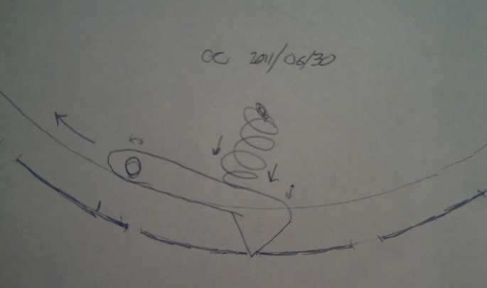 Centrifugal wedge torque converter.
That would probably have better force of torque hits than
what I've
started making. It could have both a spring and weight. The mass would
increase the force of each hit as the motor RPM went up. It would
really rumble as the car started moving. At some point of higher speed
and low torque, it might well lock the motor and output rotor together
for silent higher speed cruising.
There are some adjustments to ponder: The wedge has to
have angles both directions to allow
forward and reverse travel. The point of the wedge would start to fall
into each slot as it arrived, pushed outwards by the spring and its
mass. If the slots were wide enough and the wedge angles too shallow,
the wedge would start pressing on the trailing edge as it went in, a
retrograde force, but in a narrow enough slot, it wouldn't be falling
fast enough yet when the leading edge of the wedge hit the far side,
and only propulsive forces would be generated (to the drum rim) as the
falling wedge was suddenly forced to rise again. On the other hand, the
faster it's dropping when it strikes the slot edge, the more force the
hit will have.
LED Lighting Project
Okay, it's not the most amazing or exciting research
project -- but it is brilliant, dazzling! No new inventions, but I'm
exploring practical ways to use these devices. Perhaps commercial
possibilities lurk therein, or improvements for hybridizing cars.
In fact, by the time I'd done a couple of lights, I
started realizing that what's holding back LED usage for lighting isn't
so much the LED cost - that'll come down when usage goes up - as the
need for more practical and more attractive lighting products based on
them. Few people are
going to try to do wiring and to figure out electrical current
supplies, heatsinks, and light diffusers and fixtures from scratch, and
such bulbs as exist seem to emit nasty, bright pinpricks of light.
Especially,
they need good diffusers.
In May I ordered three different bright light emitting
diodes (LEDs), for about $10 each. They arrived on
June 9th. These "emitters" are literally blindingly bright and can
damage your retinas - one reviewer described them as being "like
welding arcs". (Somewhat like some of the newer "always glaring" car
headlights?)
I got mine from "DealExtreme.com" (Hong Kong). A solar
power/LED lighting enthusiast mentioned
another source, "LedSupply.com" (USA). (Any economic Canadian sources?)
I tried them out clipped to the regulated, current limited
power supply, clamped in a vise and facing away from me. It was after
dark. I put one up by the window and went outside. I could see the
illuminated window area. Then I got far enough back that I could see
the LED emitter itself. WOW it was a brilliant point of light, too
dazzling to look at even from way out at the street!
The next day
I went to Canadian Tire to find frosted fixtures to put them in. I
found some battery powered plastic dome lights for $5 and bought
two. You press the front dome to turn it on or off. I mounted the 10
watt, 1000 lumens emitter in one on a piece of
aluminum for a heat sink:
Left: LED emitter (DealExtreme.com #51989.
XMLAWT-0-1A0-T60-00-0001 ...?) installed on a heat sink cut from a
scrap
piece of
aluminum. The #4-40 machine screws go through (a) slots at the edge of
the LED base
(b) the aluminum sheet (threaded) and (c) thread into the plastic.
Observe battery polarity when soldering the wires.
Right: the unmodified light with frosted tungsten (incandescent)
"flashlight" bulb at center.
For battery power, three NiMH AA cells give more than the required
3.0 to 3.5 volts. So I put in a resistor in place of the fourth
cell to limit the current. LEDs need a specific current rather than a
specific voltage, and either the voltage drops until the current is
okay, or the LED burns out. I chose .5 ohms because it was the lowest
value resistor I had. I bent
the leeds around so it would make the connections in place of the
fourth cell
without falling off:
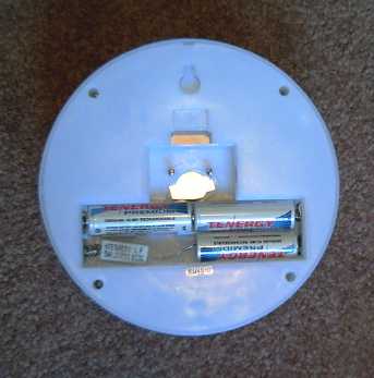
Battery/resistor arrangement. The bottom sides of the aluminum
heat sink (center, bright) and the machine screws can be seen.
All that was left to do after that was turn it on. The
voltage across the resistor turned out to be .5 volts, so the LED was
drawing one amp. The three cells made a battery of about 4 volts, so
the power was 4 watts. (1/2 a watt went into heating the resistor, so
the LED was actually only using 3.5 watts - about 1/3 of its max
power.) With a
smaller resistor, the
current would be increased. Since it's supposed to be a 10 watt LED,
the limit would be about 3 amps, at which point it should be putting
out around 1000 lumens of light - more than a regular 60 watt bulb
(~850 lumens).
But it's non-linear: at 3.5 watts, it probably puts out 400+ lumens.
Here's how it fared at 4 watts (apologies for the overexposed bulbs):

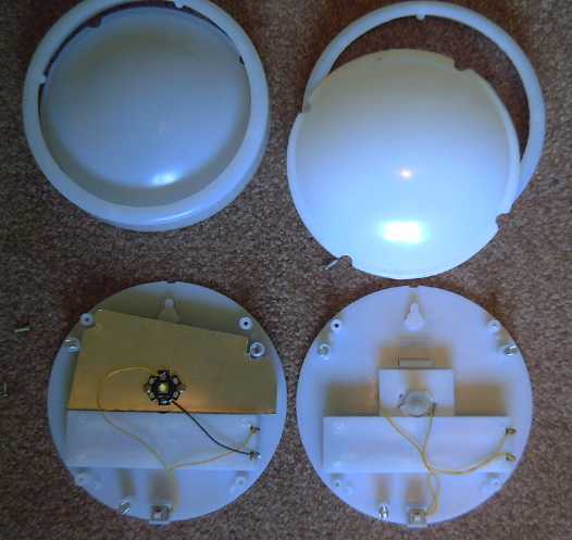
15 Watt compact fluorescent bulb in glass frosted shade versus 4
watt
LED light in translucent plastic dome shade. Even at 4 watts, the LED
light is so
bright that the whole lamp assembly glows - the sides and even the back
as well as the front dome. The CF bulb was rather orange. The LED was
brilliant white. The translucent plastic does a very good job of
diffusing the "much too bright" point source of light.
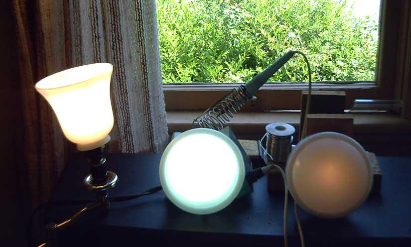
Left: 60 watt incandescent bulb (850 lumens) in the frosted glass shade
Center: 4 watt LED
Right: The unmodified plastic fixture with the original ~3 watts
incandescent bulb. (Yes, it is on!)
Rear: Daylight!
The dazzling LED is using only slightly more power than
the feeble glow of the original tungsten bulb unit.
Note: The LED is radiating light only 180 degrees, towards
the camera, while the incandescent and CF bulbs are sending it all
directions, which makes the
LED seem brighter by comparison. The LED could be made three times as
bright, but I hear they do actually burn out in a few years if run at
full power, whereas they'll last for ages at 1/2 or 1/3 power, and
they're actually most efficient in that range. At 1/2 power, they give
somewhat more than 1/2 as much light as at full rated power. And they
won't get very hot.
Even at 1/3 power, the AA batteries will only last a
couple of
hours before they need recharging. It seems odd that the makers chose
to use 4 AA cells rather than 2 D cells, which would last twice as
long. But lucky for this project, since 3 cells are required for the
LED.
This particular light would be a good car/camper dome
light, closet light, trouble light, or a light for a shed or garage
without electrical wiring, for about $20 counting the batteries.
Since it's portable, I tried it out in an outdoor shed and
in various rooms in the house. Even in rooms with a 100 watt overhead
light, this extra 4 watt unit made a substantial contribution to both
the quality of the light and the brightness of the room, and in a
hallway with 28 watts of CFs, it was about half the
light. I like the light. I didn't expect to, but now I want to add it
wherever I want bright, working light. Perhaps the cool quality could
be described as "ultra-bright moonlight". But there are various
flavours to try out.
My chief conclusion so far is that LED lighting can give
you nice light using very little electricity. If it's not
bright
enough, turn them up; add more; add varying colours - the electricity
will still be almost nothing. In the winter certain incandescent bulbs
help heat my chilly house, providing some light with the heat on those
long winter nights, but I think it would be very nice to switch all the
ones where that's not a consideration from tungsten, or from CF when
and as these mercury bearing bulbs burn out. (AFAICT, CFs don't really
seem to last longer than incandescents.)
For electric transport, all LED lights would make the
range running at night with all the lights on virtually no different
from daytime running with them all off.
LED Lighting with 120 VAC Power the Simple Way
For home use, changing batteries in lights will wear thin
quickly as a regular operation, even if they can be recharged
indefinitely. In
addition, slip-in battery connections aren't very reliable, and in
these lights in particular the cells fit too tightly and the springs
can't push them together to ensure any connection - after a while the
LED light would go bright and dim, flicker, even shut off. It worked
more reliably after I chopped some of the offending plastic supports
from the battery compartment with sidecutters to loosen things up.
I wanted to find a simple way to power LED lights from 120
volts AC to replace household lights. For the next experiment I wanted
to try various stray power adapters left over from
long obsolete equipment, and find emitters that work well at their
typical voltages, eg 9 VDC, 12 VDC... (or put, eg, three or four 3-volt
emitters in series.) The power adapters could be plugged into those
screw-in adapters that turn light sockets into plugs, in order to put
plug-in LED lights where lights are supposed to go. (What a devious,
twisted plot!)
I took the 9 volt, 10 watt, 500 lumens white-yellow LED
(Great product, DealExtreme #05876 says it's 12 volts - buyer beware!),
and found an old 9 VDC, 450mA power adapter. I found the power adapter
was putting out 13.8 volts with no load. I used two 1 ohm resistors in
series to limit the current, and the LED drew 370 mA. I cut that down
to one ohm, and it went up to 420 mA. With no resistor at all it went
up to 440mA, and the voltage was about 9.1 volts. That's 4 watts - a
little under 1/2 power (good for longevity) -- and the full power
capacity of the power adapter. In essence, the tendency of the
adapter's voltage to drop with increasing load made it a great current
limited LED power supply well matched to the ~9V LED. I have a whole
box full of various adapters that people have given me over the years.
(even after throwing a bunch out once and giving some away. Once I saw
a used computer store with a good selection, too, or perhaps any
secondhand store would have some.) Now many of them can be put to
productive use,
saving the purchase of many LED drivers!
I had more than one idea about what light to put it in,
but a frosted globe light in the upstairs hallway looked like the
simplest project - It had lots of room in it.
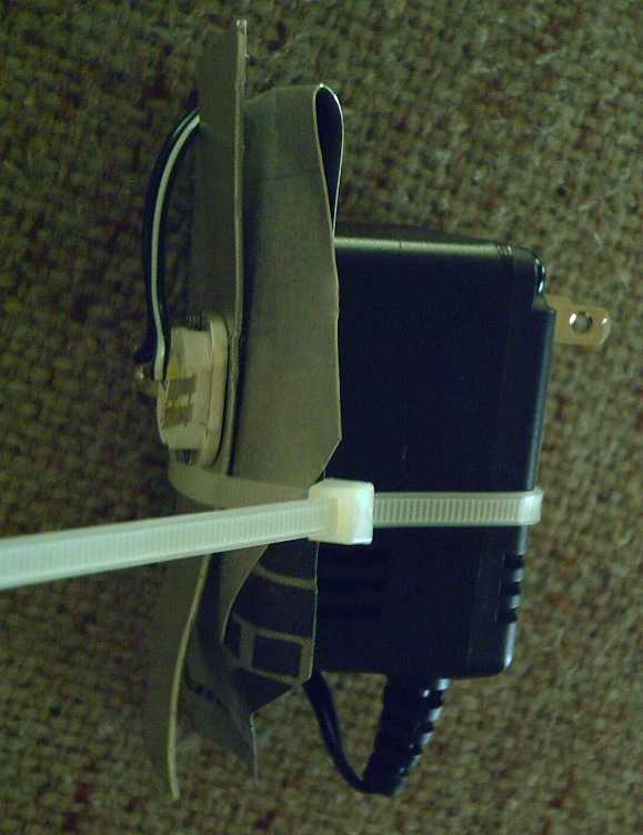
Bare LED emitter bolted to some scrap aluminum for a heat sink,
strapped
to 9 V power adapter,
power adapter leeds soldered to emitter's side lugs.
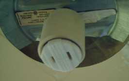
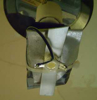
Screw-in light socket power plug adapter (Rona 3 $) --- LED - Power
Adapter - Heatsink assembly plugged in.
Finished LED light with globe washed and remounted: very nice
hallway
light, only 4 watts, for ~14 $.
Around 250 lumens of "super bright moonlight" shines downwards, but
reflections from
globe light ceiling somewhat. (Unfortunately, with this ceiling.)
If it was never turned off, it would use about 23¢ of electricity
per month
(instead of $2.30 for 40 W bulb - 100 W bulb is 6 $/mo, @ 8 ¢/KWH).
(plus however much the transformer is wasting - which might as much as
double
it. So what?)
Inside, the heatsink gets quite warm; outside, the globe and its metal
top remain cold to the touch.
I did a smaller dome light (Rona, 2 AA cells, 4.5 $) with
the third LED and a 4 volt, 300mA power adapter, but it doesn't seem
very bright. It needs more current. I also decided I prefer the larger
domes - better still, a globe.
Not all the lights will be this easy, but now I want to
convert lots more lights!
Kitchen - bathroom - livingroom - shop - garage ... If installations
don't get ugly or time
consuming, it appears that every dollar invested will pay for itself in
electricity saved in under a year of lit time, and light bulb
replacement costs thereafter are virtually eliminated. The light is
pleasant and they have no
mercury vapour or other hazardous wastes.
I'll start with the lights that are turned on most
often. First, I think the 100 watt bulb over the kitchen sink (a 26 W
CF wasn't bright enough) should become about four 4 or 5 W LEDs in
small plastic domes, spread
out more above the counter area. Or else in a globe. Perhaps four 3
volters (like the first
light above) in series powered from
one doorbell transformer. (Somebody gave me some of those, too.) Then
perhaps another transformer and 4 more LEDs, mounted in the existing
dome for the central ceiling light of the kitchen.
Even more ideally, a solar panel or two on the roof, with
NiMH,
NiFe, or new chemistry batteries to store the electricity, and some low
voltage DC wiring for lights. It all pretty much runs for free once
installed. Someone tells me Jack Layton lives almost "off the grid" in
Toronto. Wow, a politician who actually does cool things!
---
I thought that would be it for this month, but I went into
Industrial Plastics to buy a second spray can of "cold galvanizing
compound" (13$) and more epoxy resin (150$), and found an LED display
in their marine department. (Capital Iron has one too.) I found among
the lights one made for my car's interior light for 12$. I bought it
and put it in. It was just .9 watts, but much brighter than the old
incandescent. Gosh, it would seem I can read street names on the map in
the car at night again! (I haven't been able to do that for many
years.) It said it was good for 10 to 30 volts - all the driving
circuits were built in on a tiny PCB. Any that were 3 or 4 watts (the
max), were 30$
and up. These were all DC lights for boat and camper... or car. I think
there's a separate and poorly served market for nice LED
lighting products for household 120 VAC - permanent fixtures and
lamps. I ordered another dozen of the 3v, 10w, 1000 lumens LEDs like
the one in the first battery dome light. They should arrive some time
after the postal workers lockout ends.
Turquoise Battery Project
It appeared that the one remaining requirement for
properly working batteries was better conductivity. Two promising
and complementary techniques looked like they'd do the job: compacting
electrodes with
the Diesel Kleen to increase the electrode's internal conductivity, and
gluing the terminal posts to the graphite sheets
with mixed epoxy resin and graphite powder to improve the connection to
the terminal post. (And these seem to
represent
the first important advances to this area of salt-electrolyte battery
making arts since
the 1880s.)
Another consideration was that the vanadium used in May's
battery was a somewhat costly substance, and poisonous. It seemed a mix
of nickel and
manganese would give about the same voltage and at least similar
amp-hours
for a substantially lower cost. Manganese is 'dirt cheap', so depending
largely on the price of
nickel, these batteries could be potentially cheaper than lead-acid.
All these items were to be tried out in the next cell. But
with all the other projects that needed work, and a couple of days'
distraction with LED lighting, I didn't manage to get to the batteries
until the 18th except to finish putting a case together. On the 18th I
made the two electrodes and glued the positive into the bottom with the
"grafpoxy". (I made it, I can name it...)
The "Diesel Kleen"-ed electrodes smelled awful drying in
the oven, 80 minutes each. I do wonder exactly what's happening with
that. My best guess is that the mix dissolves
the graphite powder, because it's good stuff to clean off the counter
of carbon/tar (hydrocarbons)/graphite stuff, that usually only scouring
with abrasive cleansers will clean. Whatever it does, the electrodes
seem to
conduct better than without it, and have that metallic sheen, where
standard dry cell positive electrodes just look like porous "black
sandstone".
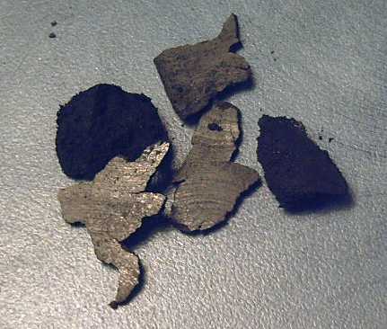
One electrode had too much 'diesel kleen' and material oozed out during
compaction.
Here is some of that 'metallic looking' carbon-manganese-nickel
material compared with coarse 'sandstone'
carbon-managnese mix from a standard MnZn dry cell. The shiny material
has lower resistance.
Cell Internal Components
Positive:
* Graphite Sheet
* Briquette:
15g monel mix (instead of just Ni(OH)2)
5 g KMnO4
14g graphite powder
1.5g Sunlight dishsoap
.2 g Sb4O6
3.5g Diesel Kleen
* Blended with mortar and pestle. (resistances read around 8-9 ohms)
* Compacted (lost 13.8g - oozed out. Made 3.5-4mm thick trode, 15-20 Ω)
* Painted on calcium hydroxide layer
* Baked in oven 80' at 110ºc
* torched
Separator:
Microporous cellophane painted with acetaldehyde with osmium dopant
Arches watercolor paper painted with zircon
Negative:
* Graphite sheet
* Briquette:
20 g monel mix
13 g graphite powder
1.5g Sunlight
.2g Sb4O6
2.9g Diesel Kleen
*****Same processes as above (8-11 Ω, none oozed out, electrode
4.5-5.5mm thick)
Cell Assembly
Positive Electrode:
Conductive Epoxy: 3.6g epoxy resin + 4.7g graphite powder
1. Spread the conductive epoxy on the bottom of the case (careful not
to get any on the sides).
2. put in the + electrode. Slide it around to spread the glue.
3. Insert the terminal post to touch electrode's graphite backing
sheet, epoxy filling gaps.
4. Allow to set. Resistances, surface to post, measured 8-15Ω.
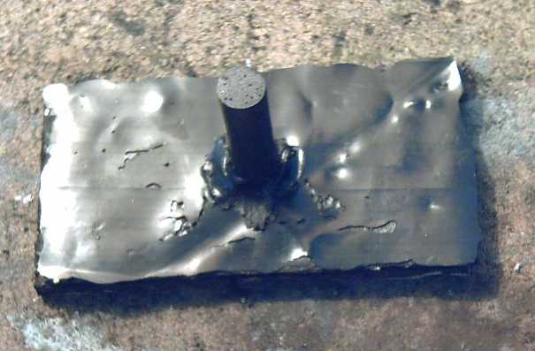
Electrode backed with 'grafpoxy' coating & glue for terminal post.
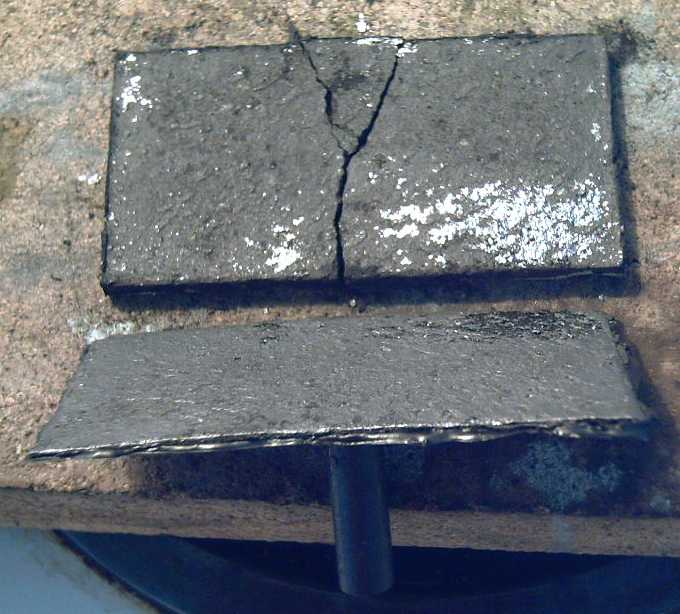
I didn't use enough 'diesel kleen' - only small areas are the silver
color and it fell apart.
In spite of having
seemingly very low resistance electrodes
this time, the internal resistance of the battery was as high as ever
if not worse. It would seem the problem lay elsewere than in
conductivity through the electrodes and to the terminal posts. Could
the ion flow be poor? Perhaps
KCl wasn't as good an electrolyte as I thought?
I added some ammonium chloride - the same stuff as in a
standard dry cell. That didn't seem to do much, though the cell smelled
faintly of ammonia next time it was opened.
Then I thought of organics. Addition of a little methylene
chloride didn't seem to do much either. What else might work?
I tried drying out the electrode and filling the cell with
toluene (methyl benzene CH3-C6H5 - a polar molecule(?) solvent) instead
of
water. As I did up cover screws, the lid cracked in several places and
a
whole corner of the case simply fell off. Evidently this stuff makes
plexiglass very brittle! That was it for battery experiments for this
month.
I must also consider the possibility that the electrolyte
simply doesn't penetrate the very fine-textured electrode pores very
well.
http://www.TurquoiseEnergy.com
Victoria BC