Turquoise
Energy Ltd. News #43
Victoria BC
Copyright 2011 Craig Carmichael - September 2nd 2011
http://www.TurquoiseEnergy.com
= http://www.ElectricHubcap.com
= http://www.ElectricWeel.com
Month
In Brief
(Summaries)
- Less energy; holidays reduce August working days.
- No time, no work, no reports on Turquoise Battery, Electric
Weel projects.
- New projects: Sprint EV conversion, solar panel for LED
lighting backup power.
- This month's general diatribe: Government Against the People.
Electric Hubcap System
* IR2133 Motor Controller V2 circuit board designed
* Improved Electric Hubcap Motor Molds
* Electric Hubcap Outboard Motor V2(?)
* A thought: Solar panels on electric car roofs can minimize
power grid impact of mass electric conversion
Sprint Car Conversion Project
* Motors, controllers, but no mechanical torque converter yet...
How about a regular electric conversion?
* The "convertable": A small,
light, cheap 4-door hatchback to convert to electric only drive
* Gearing options
Mechanical Torque Converter Project - fresh plans
* Easier construction to make one for Sprint car under hood
* Less than 1/4 output torque needed than for Tercel wheel.
* Improved idea for the conversion mechanism: narrow slots in
drum give double strength 'reflection' bounce.
NiMH
Battery Project
* Who Killed the Electric Car? -- Hey guys: EV1 used NiMH
batteries, not lead-acid!
* Nickel-Metal Hydride Battery Charging - It's Easy! An essay
* Battery Stick
improvements - light, inside-fit endcaps
allow close stacking of sticks.
LED Lighting
Project - Solar Collector
- Good
emitters with frosted diffusers make what's in the stores seem like
toys.
* Silverware Drainer Project... Huh?
* LED car turn signal & brake lights
* 3 Emitter Lamp with Hi-Off-Low switch: outshines 100 watt
incandescent lamp with same lampshade.
* Installed a solar panel/NiMH battery sticks LED
lighting
backup
power system
* Possibility of using my nanocrystalline titanium borosilicate glaze
as cover glass for silicon - or any - solar panels.
* Idea for solar power: A low voltage DC tie-in system to
save
on
electric bills without a grid tie.
* Best store-bought 120 VAC LED screw-in 'bulb' seen so far: 600
lumens at Costco for 20$.
Newsletters
Index/Highlights:
http://www.TurquoiseEnergy.com/news/index.html
Construction Manuals and information:
-
Electric Hubcap Motor
- Turquoise Motor Controller
- 36 Volt Electric
Fan-Heater
- Nanocrystalline glass to enhance Solar
Cell performance
Products:
- Electric
Hubcap Motor Kits, Parts - Build your own ultra-efficient 5 KW
motor!
- Sodium Sulfate
4x
longevity additive & "worn
out" battery renewal.
- Battery Sticks: plastic pipes for making NiMH D cell batteries:
6V (13") and 12V (25")
- NiMH individual Dry Cells (D - 10 AH, $10 -- AA - 2.5 AH,
$2.50)
- Motor Building
Workshops
...all at: http://www.TurquoiseEnergy.com/
(orders: e-mail craig@saers.com)
August in Brief
I went camping and had another trip to make 'up island' as
we say here at the south end of Vancouver Island. These trips took a
good chunk out of the month.
In addition, I'm finding that at the age of 56 I have less
energy than when I started in 2008. In 2008 I had about the same energy
and drive as I've always had. Now an afternoon work session is often
replaced
by a nap, and the amount of time I can spend actually working on the
green energy projects
during a day usually seems frustratingly little.
At the beginning of the month I designed 'version 2' of
the IR2133 motor controller circuit board, correcting the problems of
the first prototype. I didn't get it sent off for fabrication -- but
then
I haven't had time even to put the second 'version 1' board together.
Also early in the month I found a circle drill to make end
caps for battery pipes (which I'm calling "battery sticks") that fit
inside the pipe instead of outside, so everything takes less space and
is lighter and cheaper.
In the LED lighting area, I made a 3 emitter table lamp,
got ready-made LED turn and brake lights for the car, ordered more LED
car lights, and got a 65 watt solar panel for charging battery
sticks... if the power should fail, my LED house lighting can still
keep the house bright.
For motors, I improved the center body piece mold with
inner and outer lips, and 'buttons' to hold the coils in exact
position. Between the 'lips', the magnet path runs through a thinner
area, where the magnets are less likely to rub if alignment isn't
perfect.
I started rather hesitantly to put a new version motor in
the electric outboard, but didn't finish getting it installed.
Instead, near the end of the month, increases in the price
of gas got
me back to really wanting an EV of almost any sort. If I didn't have a
torque converter, I had good motors and controllers, so perhaps I
should do a 'typical' electric-only, under-hood conversion. I bought a
1990, light, 50-60 MPG, 3-cylinder Chev Sprint (AKA Suzuki Forsa,
Plymouth Firefly, Geo Metro) for under 1000$ and pulled out the engine,
radiator and exhaust pipe - 250 pounds, and I haven't removed the gas
tank and gas yet - maybe another 50 pounds with a typical level of gas.
The exhaust system alone weighed as much as an entire Electric Hubcap
motor.
The battery sticks will be somewhat over 100 pounds, so
the finished EV should be around 150 pounds lighter - around 1550
instead of 1700. Cars don't come much lighter!
I had hoped for a 5-speed manual transmission, but this
car was a 3-speed automatic. Checking the gear ratios led to the
discovery that a further gear reduction over what the transmission
provided would probably be desirable or even vital. That spoiled the
simple conversion plan! At first I thought I'd put in the 2.8 to 1
ratio planetary gear - that might be a bit cumbersome to do, but should
work out about right.
Then I thought it would be better to replace both the
planetary gear and the fluid torque converter with a mechanical torque
converter. It would need less than 1/4 as much output torque as one
directly on the Tercel wheel, should be easier to make with the sturdy
fixed alignment between motor and transmission, and an idea for an
improved converter mechanism had been brewing in my head. Full circle
from buying a car so I'd need no converter, back to wanting the
converter to make the car into an EV!
The Month's Diatribe: Government Against the People
It seems the present government of Canada has been
interfering with Canada Post, a "crown corporation" (public trust)
that has been serving the public well, to deliberately create
conditions that ensure poor service. It seems they want to drive people
to abandon
the post office so the business goes to courier companies. A recent
strike, no
doubt owing to unfair
treatment, makes the employees look greedy, and every complaint by the
public plays into their plan.
I was surveyed a year ago as to my
business postal needs, and I indicated repeatedly that the economical
shipping was of great
value for shipping lower value, heavy goods such as hardwoods, and
delivery time was rarely an issue. The post office responded, as
if deliberately from my response, by dropping the lower rate parcel
post services and leaving only the fast, more costly shipping services.
Why did I spend 45 minutes on the phone answering the many survey
questions?
Now I'm starting to understand. The purpose of the survey was to find
out how to make the system worse, and they've succeeded.
Canada, and BC, seem to have elected governments actively
working to transfer all the public's assets into the hands of a few
unaccountable people - the people who pay for their lavish election
campaigns and ensure by the most despicable, dishonest tactics that we
elect corrupt schemers instead of leaders. (I shed a tear for Jack
Layton who died of cancer this month, who would probably have been
prime minister years ago in a fair system that elects people instead of
partisan political factions, "parties".) BC Hydro and BC Ferries were
created by previous BC governments only because private companies
weren't
working. Now much of the value of these prize public assets has been
involuntarily donated by the public to the rich.
This isn't free market or anything: it's theft. If these governments
believed
in the "free market, capitalist" system they pretent to espouse, they
would at
least have put shares for these organizations for sale on the stock
markets and the sales from
the
shares into the public treasury. Instead, suddenly the wealth is in
private hands and all the public is left with is government debt and no
assets.
People are fearful, almost
panicked, by the deteriorating economy. These governments promise
"stability" while they steal the remainder of public
wealth and move us all towards poverty and serfdom to the ultra-rich
gangsters to whom they owe their allegiance -- the very cause of the
deterioration. Betrayal of public trust
is a capital offense on more civilized
worlds. Here it has become so prevalent that there's no one left with
the power to prosecute.
The many riots seen around the
world recently may be just the beginning of a dreadful harvest of
politically and economically disenfranchised citizens who have been
until now the middle class, who have no say in their governments,
governments that here can somehow be elected and re-elected but which
have become thoroughly corrupt and are working against the public they
are
supposed to serve. The fields are ripe for the harvest, and upheavals
are in the works. People who a few years ago would have staunchly
resisted change
are becoming ready to embrace it. It is up to each of us to ensure that
our human family makes changes for the better rather than for the
worse. We need freedoms - religious, political, economic, social, and
free time - to live out lives as we choose and fulfill our individual
potentials. not endless petty rules and regimentation. not 8 hour
workdays and "needs" being thrust upon us by clever advertisers. not
pricey garbage being thrust upon us by vested interests, like petroleum
cars, nuclear power, cow hormones, pharmaceuticals and weapons, so they
can make more money at our expense, and at the expense of the planet.
The time is ripe for this to stop. A materialistic summer
is drawing to a close. Those involved in and profiting from such
ventures should take a hard look at
what they're doing to their fellow Sons and Daughters of God and where
they themselves are headed spiritually, and at the misery, death, war
and mob violence their selfish choices are unleashing. "You can't
take it with you", but you do take with you the spiritual fruits of
your life. Dylan's song comes to mind:
"and how many times can a man turn his head,
pretending he just doesn't
see?
the answer my friend, is blowin' in the wind;
the answer is blowin' in
the wind."
Electric Hubcap Motor System
One step I took in August was to get enough #11 magnet
wire for foreseeable needs. Supermagnets have tripled in price since
February (but appear to have stopped rising) and NiMH dry cells
suddenly went up 40% in July. I wish I had purchased more of both.
Might copper pull a similar unpleasant surprise? I felt it was
important to have upcoming needs met, and not with a hodge-podge of
scrap wire. The neighborhood motor repair shop had 40 pounds left of a
50 pound spool bought for a job that was finished, and (as the motor
repair person was too busy to divvy it up) I bought it all for $380,
which is anyway the lowest price I've seen. I think I'm pretty much set
now unless epoxy resin suddenly jumps.
Who would have thought that making an advanced electric
motor would commence with cutting sections of polypropylene landscaping
cloth and then ripping them into strips? Yet cheap polypropylene (PP)
must be one of the toughest things around, stronger and lighter than
fiberglass. Carbon fiber doesn't have PP's tensile strength. I can't
imagine hemp or other organic fibers
having the same strength or the durability. Epoxy is strong and better
than polyester (resin), but even so without support might crack.
Together, PP-epoxy is probably about the best composite one
could mold - the toughest, and economical and relatively lightweight to
boot.
The epoxy resin is nevertheless pricey, and the molding
process is time consuming, tedious and gooey. But I made some good
motor form
improvements this month that couldn't very well be done any other way
but
by molding.
Mold/Motor Improvements
Last month I put together the first motor with a flat
magnet rotor. The rotor (just) fit, but it would have been better if
the rotor
compartment was about 3/16 to 1/4" wider. But the 2" wide black PP
strapping was the widest I'd seen. On a camping trip, someone had
2-1/4" wide yellow PP webbing to fix his aluminum frame rocking chair
(a rather unique item). Aha!
But while molding the second motor, I had the thought to
router out a groove in the edge of the top insert for the center ring,
to make a 1/4" tall lip around the edge. That would add the 1/4", make
the edge stronger, help center the rotor cover better, and leave a bit
more edge exposed on the other side of the ring for fastening the
stator screen to.
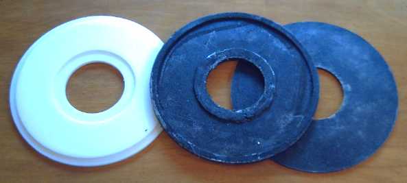
Center ring top of mold and ring, a bit thinner but with thicker inner
and outer edge
"lips".
Old uniform thickness ring at right.
Other Concerns: I
also kept thinking about the
warm coil mounting bolts. I've shrunk them from 1/4" to #10, so they're
wasting less
energy, but not zero. They might perhaps be replaced by a plastic
(nylon?) form needing only one bolt instead of two, that the coil fits
over. This could also position the coils more
exactly - they are often a little 'in' or 'out' from each other.
Various designs came to mind, then I had another idea:
what if bumps, "buttons", the size of the hollow core centers were
simply molded into the PP-Epoxy ring? Simply by clamping the two rings
together anywhere, the coils would be fixed exactly in place. And the
clamping bolts could be placed in areas of thick composite to hold more
securely - eg, in the proposed outside lip and another new lip inside.
They
would then be outside of the magnet
sweep path, so they would also
have lower eddy currents. And the magnets could never rub across a
piece of metal.
As yet another added bonus, the main body of the ring
could be made a little thinner, shrinking the overall motor thickness
yet a little more.
I worked all the co-ordinates (spreadsheet) and the router
sequence out and started making a new mold. As it was being cut, I got
another idea: to put "lips" around the "buttons" to sandwich the core
securely while exposing the sides of the wires to the cooling air and
removing clamping pressure from the coil wire. It's only a little more
cooling on a very efficient motor, but still heat is the ultimate
limiting factor in how much continuous power a motor can put out, so
anything that improves cooling is a plus. Luckily, I thought of this
while everything was still in progress, so I was able to add the lips
with no misalignment. I did take a chance by routing without being able
to do a test run on a scrap piece, but I got it right. The routing
depth was just slightly greater than I'd planned, but that has to be
set up at the time anyway - a test run wouldn't have helped. It was
close enough, and will make a good air space for best cooling.
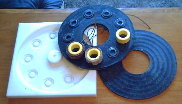
New mold and ring with cast "buttons" to mount the coils on (flip side
of ring shown above), old flat ring.
The coils could be shifted back and forth a bit, so on the 31st I put
the mold back on the CNC machine
and made the buttons a little taller, and with solid centers. The mold
is pretty thin in the bottoms of the holes now.
I was thinking it was too late for this motor, but then I
considered that the rotor end was unchanged, so I had two good rotor
ends and one center, which could be fixed up, "good enough", by filling
just the additional hollows and putting it back in the mold. Then with
one new center ring and two new stator end rings, there'd be the parts
for two motors in the new, improved style.
Another item still
needing improvement is the durability of the ilmenite in sodium
silicate paramagnetic coil
coating. The coatings still flake off easily. I intend to play with
"filler" additives including zinc oxide and clay-like substances.
The reader will note that all this has gone from the big
changes and wide range of constructions coming and going over the last
three years, to tweaking the construction details of what is becoming a
pretty finished enclosed motor.
It's the honing away of some rough edges.
International Rectifier MOSFET Controllers: "ITrip"; selection
Most of the IR mosfet drivers have a current limiting
shutoff called "ITrip" fixed at 0.5 volts. I think to myself: Ouch, .5v
* 127 amps is 63.5 watts in the sense resistor! Why did they use such a
high voltage? (not to mention: Why is it a fixed voltage at all?)
Finally it occurred to me... of course, they're thinking
of line voltage motors with much lower currents. The maximum voltage
ratings are 600 or 1200 volts. For example, 5HP at 240 volts is only
around 20 amps, or 10 watts in the sense resistor.
I work around the fixed current limit by using the
built-in op-amp as a comparator between the power control setting and
the actual current, and feeding the output as a digital signal to
"ITrip". For this purpose, the op-amp output might as well have been
tied to ITrip
internally, saving two pins to allow for a forward-reverse input pin.
(I can see doing it as a 24 pin single chip brushless motor controller.
Sigh! Sometimes I wish I could design chips myself.)
I designed and layed out the PCB for the corrected and
improved 'version 2' of the IR2133 motor controller. I was having
trouble fitting the additional components, and finally opted for the
small SOIC version of the 74ALS86 XOR gate. I managed to shrink the
width to 1.65" to allow slightly thinner chassies.
Then (dumb time) I went back to IRF.com to make sure I
hadn't missed any chips that might be better than the IR2133. One
controller (IRS26310) had an RC timeout for overcurrent shutoffs built
in, and safety shutoffs for the high side MOSFETs in the event of a
short circuit. Nice, but it was missing a couple of valuable IR2133
features and the RC actually only saved one resistor over my 'RRC'
design. None of them had the "forward-reverse" pin I wanted (to
eliminate the XOR gate) or any other special advantages. Weeding out
the selections one by one, I ended up back at the IR2133.
In the selector guide (a different one than I found
before) they all said "0.3 to 5 KW" - seems they're the right chips for
a 5 KW motor. 3 of them for the 15 KW Electric Weel is of course still
right.
"Modernized" Electric Hubcap Outboard Motor
Let's see... I have great motors, and I should have great
motor controllers once I get the revised circuit boards. But no means
of coupling them to a car wheel has been proven to work yet. Even the
motorcycle tests were disappointing, the gear ratio evidently being
akin to 'stuck in third gear' inappropriate. What uses could people
immediately
put the motors to that might get a few motors and controllers into use
out there?
Last fall I turned my Honda 7.5 HP outboard motor into an
Electric Hubcap
Outboard. Shortly after that, I started improving the motors in
efficiency and design. It
seems only natural to upgrade the outboard to the new design. The old
motor
was a slightly undersize "open frame" prototype with no case (in fact,
it was the one that got the car to crawl across a parking area
connected
direct to a wheel in October 2008), and it was a good fit under the
hood of the outboard. The new motor, though thinner with a flat rotor
and in the trim final production size (smaller than the initial
production
size), is enclosed in a case. It seems it'll just barely fit with two
sides of
the
stator end ring trimmed off, the coils themselves almost touching
the sides of the hood. The hood might need to bend a little and jam on
if not fit nicely.
With the ultra-efficient Electric Hubcap motor, the
Electric Hubcap Outboard should theoretically take a boat a little
farther, or faster, with the same batteries than an otherwise identical
conversion using any other motor. Boaters might like that.
I decided I'd use the motor I made last month, replacing
the shaft with the one that fits onto the outboard's drive shaft... But
on
the 27th I bought a
very small hatchback car to convert to electric-only via the regular
transmission. Suddenly the outboard motor takes a back seat!
Solar power idea: solar panels on electric cars
At first glance, putting a solar panel on the roof of a
car may seem
like trying to drive spikes with a tack hammer. Even the low-power
Electric Hubcap motor uses up to 5000 watts, and a 'full size' solar
panel
that would take up a car roof area only makes 230 watts directly facing
full sun.
But cars sit a lot, and we may instead look at the figures
in terms of charging the batteries and travel distance. The EV-1 used
around 225 watt-hours per
mile.The
owner of an electric converted Suzuki Swift says he uses 100 to 180
watt-hours per kilometer depending on driving conditions -- average 140?
If we then said the solar panel would average 140 watts,
over an 8 hour sunny day it would collect enough electricity to drive 8
Km free. A larger station wagon just
might fit two panels and double that. It may well be, for example, that
most people won't need to plug in their car at their day job. That's a
lot of energy not
needed from the power grid.
This is also a good argument to those detractors who say
"But where would all the electricity come from if we all drive electric
cars?" That's a silly argument to start with, but here's another good
answer.
'Full size' solar
panels are today over 500$, but
they're starting to
become economical enough for volume production and will continue to
come down as usage increases. (As I write this newsletter I see some
under 400$, at solarpanelsonline.org) I can see doing a solar charging
system on any car with 500$
as the total price in 2 or 3 years.
These panels are around 39 x 65". That's convenient... the Tercel would fit up to around 40 x
78",
and the Sprint 40 x 62". Too wide and you'd bang your head getting in
and out. Length can go over, as long as it's mounted high
enough the tailgate has clearance to open, or it can stick forward a
bit. In hot climates a cover shading the windshield could be a good
thing. Multiple smaller panels might produce a convenient voltage for
charging 42 volt battery systems. Additional smaller panels could also
be located on trunk, hood, body panels and doors if it was felt to be
worthwhile.
Sprint Car Conversion Project
Next Car Plan?
At first I thought my plan for the next try to get a car
going would be to make
two more motors and fit them both to the Tercel with the 2.8 to 1 ratio
planetary
gears. With motor controllers that give good torque at zero and low
speed now, this plan seems more likely to succeed than last
time, at
least with two motors if not one.
Or... an 'under hood' electric motor conversion
But near the end of the month (after thinking I'd better
be very frugal with my remaining money for the rest of the year), I
started thinking that
with good motors and controllers but no torque converter, it might be
better to acquire a very small car (perhaps a decent looking one with a
blown engine?) and do a "typical" electric conversion, with an Electric
Hubcap motor under the hood, keeping the transmission with clutch and
gears in spite of its losses. Surely it
could hardly fail to get moving in first gear and with a clutch?, and
I expect it should be okay for around town even if it proves
underpowered
for the highway.
A successful project would demonstrate the
efficacy of the motors and controllers, get a car going on electricity,
and assuming I later get systems with mechanical
converters working, it could provide good data on the improved
efficiency of that system. Especially, one could be mounted on the same
car and the various parameters compared, in particular, acceleration,
driving range, and ease of use.
I decided my priority for the moment is a working electric
vehicle, period!
On the 27th I looked on UsedVictoria.com and saw a 1990
Chevrolet Sprint (AKA Suzuki Forsa, Suzuki Swift, Pontiac Firefly, Geo
Metro), a 1700 pound
hatchback with a 1 litre,
3-cylinder engine, at Fuji Motors. I was somewhat familiar with that
50-60 MPG(!) model, having almost bought one new in their second year,
1986. I think that before this car, Suzuki
only made motorcycles. Fuji
wasn't too far
away, so I went and had a look.
This one was a 4-door automatic.
The dealer seemed to have
some
misgivings about selling the car, which he had on consignment for the
owner - I was warned of several problems. "It runs, but it's not very
good." he said hesitantly. I
said some of them (like the engine burning oil) were no concern because
I was converting it to electric, and that I wanted it because it was
small and light. I had hoped to start the project for under $500; the
total was $812 ($700 + taxes). But except for faded paint and
some bad rust at the very bottom of the sides, the car looked quite
decent inside and out despite the age and mileage (237 Mm). The tires
were good. It was just what I wanted except for the automatic
transmission. I might look long and hard and still come up with
nothing as good for cheaper... unless it was a bigger car. The dealer
drove it home for me on his dealer plates (jump starting it with a
working
battery) since I didn't want to license it for now - Great! No towing
bill! - I didn't even have to ride my bicycle to Fuji. I drove
him back in my Tercel.
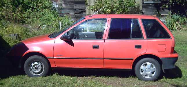
Sprint (port)
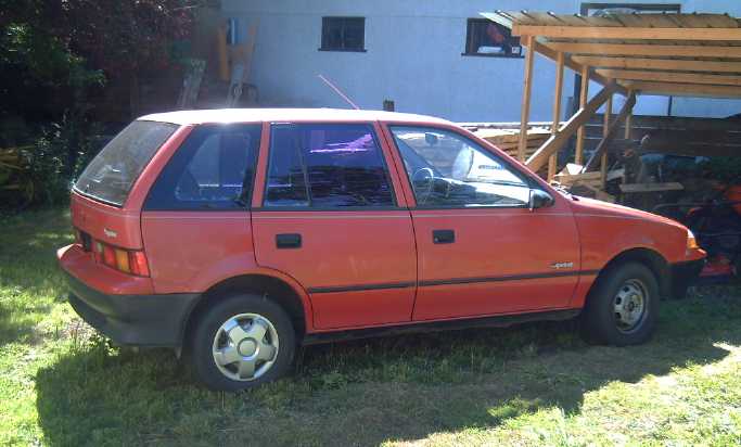
Sprint (starbord) and "carport"
I only drove it across my own lawn to the back after I got
it,
nose into an open shed "carport" to cover the hood. I used my original
22.8 amp-hour NiMH battery - big enough for this car. I noticed that
the brakes were sticking and the car didn't roll well. It needed new
brake cylinders - and a disk - ugh! What did I expect for $700?
(Another $70 for a front brake caliper and some brake fluid - it's
starting to eat money already
and it's not even on the road yet! I got it at Key-2-Parts -- best
deal, and I think this was their parts delivery car at one time. I
remember seeing it around, and the dealer said it had been a car parts
delivery car. The disk
and the other caliper can wait.
Bonus:
the radio/CD/USB-stick player works and the ashtray is clean!) By
evening it looked a lot clearer under the hood. The next day I rigged
up a winch on the low "carport" ceiling and by evening the engine block
and all
the main superfluous pieces except the gas tank were out.
Some cables, wires and tubes going to the automatic
transmission made me nervous. How did all that stuff work? Would it be
hard
to get it to shift properly? I couldn't even get it out of "park" until
I plugged it in and connected a battery - and even then not until I
figured out you also had to have your foot on the brake pedal to unlock
it. I got a repair manual at the library. Some study showed it seemed
to have going in: gas pedal linkage,
speedometer, and the shift lever. No tach (unless it was an electrical
signal). It would seem it shifts based on vehicle speed, and
downshifts at a high throttle setting. Those wouldn't change (much), so
it should work.
One turn of a wheel turned the transmission input shaft
about 1-1/2
turns, so (counting the opposite wheel not turning) the ratio was about
3 to 1. The fluid torque converter should
make that more like 5 to 1 for starting to roll. I think that was first
gear,
but
nothing changed when I switched the shifter to reverse or to
neutral. It wasn't as high a ratio I was hoping for... from a 5-speed
manual transmission unit.
I took a ring piece of a Hubcap motor and checked the fit.
The new smallest (11.25") diameter motors barely (if at all) clear the
rubber boot of the inner starboard CV joint, which is - barely -
behind. (The transmission wall has an arc cut out of it for this to
fit.)
...The outboard motor and the Sprint, just barely a fit; also
just a
fit on the Sprint's 12" wheels if wheel mounted -- lucky I decided to
make the cases as small as I reasonably could! However, there's no
problem with motor length (thickness?) for this one, so I might use the
spare 10" brake disk magnet rotor with its one inch hub rise, to save
time.
There was however room to spare in front where the
radiator was (and immediately behind it) for the 7 banks of battery
sticks, or even 9 or 10 banks. (I seem to be assuming I'll be donating
my present 245 NiMH D cells to this project.) To reduce electrical
needs a bit, the LED car lights I've ordered will be going on the
Sprint, and the headlights are small bulbs instead of big sealed beams,
so they'll be easy to change.
I weighed the parts coming off the car: radiator, engine,
exhaust piping and muffler. The total of around 250 pounds will be
replaced by only about 150 pounds of electric motor, controller and
battery sticks. That makes it lighter (counting another 50 pounds for
absent gasoline) by about 150 pounds - equivalent to "minus one"
passengers and just 1550 pounds. Of
course, with money, one could easily add that weight back in in
additional batteries for greater range. Or, for least initial outlay,
lead-acids
could easily add 300 or 450 pounds and monopolize the rear luggage area
and/or
one of the back seats.
I'm still somewhat puzzled that the motorcycle didn't
perform better than it did, being
a total load of
only about 350 pounds, with a 4
to 1 speed reduction chain drive. Of course, having only two banks of
batteries at 36 volts limited
the current - at first, briefly, to around 80 amps (when it climbed a
slight rise), and soon to 60 (where it would barely do level ground).
Doubtless I was overloading those first six battery sticks.
The Sprint's tires are about 20" diameter and
the motorcycle's are 27", a ratio difference of 1.35 to 1, so 5 to 1
on the Sprint is equivalent to 6.75 to 1 on the bike, which ratio would
have
produced better results.
I'll try out with at least four banks of batteries on the
car (if not all seven), and 42 volts instead of 36 (equivalent 14
sticks (or 25)), but the car is certainly heavier than the bike. I
thought going through a transmission would solve all the problems, but
the ratio still seems low and at
this point I'm apprehensive about whether it'll
move the car acceptably -- or even at all.
I'll certainly take the best shot at it. If the worst
comes to the worst, there's more options that can be invoked. First, I
could mount the 2.8 to 1 planetary gear between the motor and the
transmission. That changes the total reduction ratio from 5 to 1 to 14
to 1. Should that mysteriously still fail to get the car rolling, or if
it limits top speed too much, there's room for two motors in there on
the same shaft to double the torque - with or without the 2.8 to 1
planetary. Then there'd be plenty of power even for the highway if only
it had the battery range to go somewhere on a highway!
Maybe I'd do it the other way around... install the
planetary gear initially, and remove it if it didn't seem to be
needed. The planetary gear reduction also would doubtless have got
the motorbike going nicely.
But then I started thinking again of the
mechanical torque converter, and that it might be readily applied to
this project. It would eliminate both the fluid converter and the
planetary gear and prove the conversion principle, and it would only
need to supply 1/4 or 1/5 as much torque as driving the Tercel wheel
directly, much improving the prospects for success. Here we're back
full circle to the torque converter project!
Whatever the gears, the next things that need assembly are
the motor, another motor controller, and the 28 battery sticks. - none
of these are ready. (unless I use the motor from the outboard.) Then
they'll need installing, which will mean a custom shaped plate to bolt
the motor to the transmission housing, a main solenoid in the
controller, and brackets and clamps for the batteries. Before the final
motor assembly, I'll need to know exactly what the shaft will fit to
and how:
- planetary gear and fluid torque converter
- mechanical torque converter
- planetary gear alone
- fluid torque converter alone.
(Any change in type will probably mean disassembly and
shaft replacement.)
A potentiometer will need to be mounted for the gas pedal,
and a forward-off-reverse switch, or at least on-off, besides the
ignition key. I want to see how much pressure the brake pedal needs
before I bother getting a vacuum assist unit for the brakes - it is a
really small car and regenerative braking will help. The 42 volt
electric heater/defogger - and a new front left brake piston and any
other repairs - and insurance - can wait a while, at least until it's
running well. It'll be a lawn car until then!
Mechanical Torque Converter Project
On the 30th, having started the Sprint car electric
conversion, I had the thought that if I could replace the
Sprint's fluid torque converter with a mechanical one, the greater
torque multiplication would make using a planetary gear redundant.
Altho only a 10" diameter converter drum would fit instead of 12",
there's more length
to work with than on a car wheel - the motor shaft can be any length I
want really - and the 3 to 1 gear ratio to the wheels following the
converter means it only needs 1/3 the output torque. And the wheels are
a little smaller and the car is lighter, so it might really be more
like 1/4 to 1/5 the torque. And I have in mind a modified torque pulse
mechanism that should be better and easy (relatively) to make.
Alignment is simplified by the fact that the motor is held
rigidly in place. It doesn't pivot as it must for suspension on the
wheel. The
'odds' on acceptably making what I have in mind and having it work seem
favorable.
I came
up with a good plan to put the output shaft/drum on bearings around the
motor shaft to keep it lined up: by clamping an SDS (or SD) 1-15/16"
taper lock shaft bushing with the
drum onto two tapered trailer bearing cups, sandwiching two bearings
back to back, perhaps with a short spacer between them. (Or it might
have
to be a 2.0" shaft size SDS, with the slot ground a little wider with
an angle grinder -- the bearing cups are slightly under 2 inches.)
Thus the layout would be: motor with about a 3" shaft
sticking
out, an SDS coupling clamped onto the shaft holding the input rotor,
and a second SDS (or SD) coupling, on bearings, holding the output drum
outboard from that. Somehow the output rotor needs to attach to the
splined shaft in the transmission. When the motor is attached to the
transmission housing, the output rotor will have no room to slide off
the end of the motor shaft.
I'm reluctant to chop up the fluid converter to extract
the spline fitting - in case this doesn't work, I'll need that fluid
converter.
I couldn't find the spline fitting, but the next day I
thought: an SDS coupling of the right inside diameter, holding the
slotted output drum, will clamp on and likely work just fine - yay, a
plan! That will replace the above SDS holding the drum on bearings, and
shorten the mechanism.
I'll want one smaller bearing on the protruding tip of the transmission
shaft, with a tenon over it on the motor shaft, to align the motor and
transmission shafts.
The bottom
couple of inches of a 10" aluminum saucepan with fairly thick walls
could be used for the torque converter drum.
The torque plan is to slot the drum with about 30 narrow
slots, stuck by pivoting wedge arm pieces, pushed outwards by springs,
along the lines of those in the top-right drawing from May (ignore the
other drawings), which I
think are the best design idea:
The narrow slots are a new feature of the plan. With
narrow slots, the wedges on the arms are still traveling downwards when
they strike the far edge of the slot, with the back side of the wedge
still in contact with the leading edge of the slot - unless the
difference in rotational speed causes them to lose contact. That,
within limits, will only increase the downward force. The bounce
reflection gives the hit twice the force it would have if it was
bottomed out and hence vertically stationary when it strikes the far
edge.
The number of wedges can be theoretically anywhere up to
the number of slots. They should all operate simultaneously... as long
as the motor can push the wedges out of the slots from a stop. Tho I'm
not sure how many will needed or optimum, the more the simultaneous
hits, the stronger the pulse of torque. If I make the rotor with 12
wedge holders (or places to mount 12 - if they'll fit), it can have 2,
3, 4, 6, 8, 9, 10 or 12 wedges applying symmetrical rotational forces
around the drum.
With a few techniques and key pieces, I think the
construction seems doable, and I have good hopes for the wedges and
narrow slots making sufficient torque. Ironic that I started the Sprint
car
conversion because I don't have a working converter yet; now it may
lead to making one. I
hope I can find time to get to it
in September.
On September first I ordered an SDS 7/8" bushing to hold
the torque
converter output drum to the spline shaft in the transmission, and I
bought a 10" aluminum saucepan and cut it down to make that drum.
Nickel - Metal hydride Battery Project
Battery Sticks V2, 12V & 6V.
I'm repeatedly amazed that
most people who say they've
watched Who
Killed the Electric Car? seem to think those EV-1's ran on
lead-acid batteries. They've missed one of the key points of the movie:
that the cars became sporty, popular cars instead of so-so slugs when
they switched from lead-acids to nickel-metal hydrides in 1997 -
batteries that
looked as though they'd outlast the cars. Ovshinsky, who was
interviewed in that movie, created the metal hydride that made the
batteries great, at home, after he retired from being a
chemistry professor at a university, using his pension for research
funding.
And of course many or most hybrid car batteries are NiMH.
Evidently newer ones are composed of NiMH D dry cells, now - the same
as what I'm using. They're lightweight, electrically excellent, and
readily available.
Ovonics recently estimated they
could (if they were permitted by Chevron) produce NiMH car/EV batteries
to sell
for about 200 $/KWH, which isn't so much more than lead-acid. And with
recycling of batteries, that could come down further.
Charging NiMH Batteries - It's Easy!
There seems to be a lot of confused information about
charging of NiMH dry cells on the web. Much of it would lead you
to believe that NiMHs are a finicky chemistry and that charging them is
an
exacting science. Nothing could be farther from the truth. Some writers
appear to be exaggerating minor characteristics to make them look like
major problems in order to promote other chemistries for financial
gain: lead-acids need much more frequent replacement, and lithiums have
a higher selling price - NiMH makes the seller - and costs the buyer -
the least amount of money over time. (Nickel-iron batteries have been
similarly
maligned and worse for a century. The writers, usually lead-acid
battery sellers, play on peoples' unfamiliarity with nickel-iron to
make these fine, exceptionally long life, batteries sound utterly
worthless. At a battery conference this year, keynote speaker Peter J.
DeMar, known as "the lead-acid battery guru", shocked everyone with his
talk "Edison Had It Right" [with his NiFe batteries, lasting a
century].) The known high self discharge of typical high-rate NiMH
(and NiFe) cells is a case in point: "experts" make it out to be a
major problem, for all practical purposes ruining the chemistry. But
how
often does your car sit for weeks between uses... and then need to
drive it's maximum range? Even
then, would you not simply keep it plugged in and "topped up" when it's
idle? The electricity to do so is pretty trivial. And the low
self-discharge NiMH cells
available for (eg) battery clocks and smoke detectors are rarely
mentioned.
NiMH cells will take
charge rapidly, and they can be randomly partly charged or discharged
at will and left sitting in any state of charge (except totally
discharged) with no ill effects. Newer D cells are good for 20-50 amps
discharge rates, and high rate AA cells can replace short lived NiCds
in applications such as cordless power tools, and give longer
running times as well as long service life. NiMHs only lose a certain
amount of their permanent capacity if they're discharged to under about
1.0 volts - that's over 90% discharged. Until about 80% discharge,
expect them to be stable at about 1.25-1.15 volts under any reasonable
loads. They can really only be killed by being short circuited or very
seriously overcharged.
But a clear distinction must be drawn between fast
charging, say in under an hour to 3 or 4 hours, and regular
charging in maybe 8 or more hours.
In rapid charging, there's little problem until the cells
near full charge. Then oxygen starts bubbling rapidly from the positive
electrode. The faster the charge rate, the more furious the bubbling.
The cells are made to withstand a certain amount of this, but that's
greatly exceeded in fast charging. The oxygen diffuses over to the
negative electrode and spontaneously discharges a hydrogen ion (proton)
from the hydride, a chemical burning reaction creating water and heat.
At such fast charge rates, the oxygen gas diffuses over to the negative
electrode faster than the regular liquid electrolyte transfer of ions,
creating a lowered internal resistance and the charge voltage (but not
the cell voltage after removal from the charger) actually drops instead
of continuing to rise. Thus the usual voltage-rise indication of 'end
of charge' is
inverted, and only battery temperature is truly a reliable guide that
it's being fried.
In addition, fast charging multiple cells in parallel can
result in
problems. One may reach full charge first and overheat and fail before
the
other one is fully charged.
And
the faster the charge, the higher the voltage that needs to be applied
to obtain it and the less efficient the charging becomes. Unless the
cells are needed urgently, rapid charging as a standard charging
technique is to be avoided, since it is likely (IMHO) to shorten the
life of the cells, and charging problems have a good chance of
immediately
destroying them. For large batteries, eg for EV use, the extra energy
used for charging so rapidly may perhaps also be significant.
NiMH cells can however take rapid charge up to the point
of
getting near full charge, so they are excellent for automotive
applications like regenerative braking where some charge is restored
very rapidly, but they'll never be overcharged that way because more
energy is lost in driving than is gained. (unless of course you start
at the top of a mountain with fully charged batteries.) The much talked
about supercapacitors are superfluous with a NiMH battery.
For slower charging, the fast charge problems disappear
and everything is much more casual. With a ten hour charge rate, the
batteries can withstand a few extra hours of charge, and at 20 hours or
more, they can be left in for extended periods and only get a little
warm. At a rate of perhaps 50 or more hours, charging voltages are
lowest and trivial stress is placed on a battery even if it's left on
indefinitely. Of course, no one wants to wait days for their cells to
charge. 8, 10, 20 and 25 hour charge currents are common. Constant
currents do work -- but there's a better way to charge NiMH batteries.
A constant voltage charge IMHO is optimum: at first the
cells charge very rapidly, even a two hour rate or faster for the
first
few minutes if they are quite depleted. As they charge, and the battery
voltage comes up, the current drops gradually and naturally, at each
moment being, IMHO, about optimum for the present state of charge. At
full charge, the rate has dropped to a 50 or 100 hours rate and below.
What is the best constant voltage? First I must point out
that this voltage must be a steady DC level, not the pulsing
voltage put out by many chargers that merely averages out to
the desired voltage. The cells will respond to the peak voltage of the
pulse and continue to charge, resulting in overcharge.
One circuit I saw on the web used 1.35 volts per cell.
Currents will certainly taper off to nothing at that voltage, and the
charging will be quite efficient, but the cell may end up with perhaps
10% less charge when 'full' than using a somewhat higher voltage. In
addition, the higher the constant voltage, the faster the un-full cells
will
charge. My feeling is that optimum voltage is around 1.37 to 1.39
volts. 1.395 volts is about the upper limit: above that, the currents
will stay too high once the battery is charged, and that steady-state
current rises
rapidly with small increases in voltage. (Note that for 10 cells, the
automotive standard of 13.8 volts is not only acceptable but ideal,
making NiMH D cells excellent replacements for lead-acid car batteries.
Older vehicles, using light bulbs for voltage regulation, are likely to
rise to 13.95 volts with NiMH cells installed - still just within
limits.)
With this constant sort of constant voltage charging,
cells placed in parallel will all charge fine and any that are more
discharged
than others will charge faster at first, so they may all finish
charging fairly close to the same time. If not, it still isn't a
problem.
Admittedly much of my more recent and extensive charging
experience is with Tenergy brand NiMH cells. They appear well made, put
out a lot of current when needed, and met their claimed amp-hours specs
when I tested an AA and a D. Certain "off-brands" are known not to meet
their claimed specs, and there's some I'm suspicious of. Other brands
may have slightly different optimum voltages... but I suspect that for
1.38 volts charging, all common NiMH cells would be within limits.
Temperatures below -10ºc (typical rating) may pose a
problem for typical cells. There are cells rated to -30. Coldest I've
been able to try here was -6ºc last winter. The car started
smartly, much the same as when it's warm, and no problems were
encountered during the slightly sub-zeroºc weather periods.
Prices
The 40% NiMH price increases during July seem typical of
Chinese advanced technology products and are unlikely to affect NiMH
dry cells alone. (Then near the end of August there was a "15% off"
sale.) It also occurs to me that although only AA size NiMH
cells are available in Victoria stores for small volume uses, car
makers have
evidently been using NiMH D cells in their hybrid batteries. Since that
would mean 120 or more D cells per hybrid car, production volume of
NiMH dry
cells may be much greater than I had expected, which in turn means the
prices aren't likely to drop quickly "as more people use them".
On the other hand (assuming price increases were across
the
board and not just for NiMHs from Tenergy) the wholesale price of
lithium ion cells (from Thundersky) is higher than NiMH retail. And,
though lithium ion claims longer cycle life than NiMH, several thousand
cycles versus 1000 cycles, laptop computer users have been reporting
opposite results - that computers with lithium ion batteries need new
ones more frequently than those with NiMHs.
Improved Battery Sticks
The Problem: find a practical and reliable way to make many
small cells (at least half again as many as here - preferably double
or triple) into one big battery for electric transport. Soldering them
all together is tedious, and I found that stressed joins can acquire
metal fatigue
with road bumps and vibration in actual vehicle use.
The Solution: I found a great way to make a battery case last
month -- by simply putting batteries into plastic plumbing pipes.
The "1-1/4 inch" PVC irrigation pipe has about the right
wall thickness - enough to make it stiff but not needlessly heavy -
though it's a bit of a sloppy fit on the inside. D cells are a little
over 1-1/4" diameter, but this pipe size actually has the same O.D. as
"1-1/4 inch" pipe with thicker walls rather than the same I.D, so that
the same outside-fit fittings can be used. It is actually about
1.5" I.D.
The more objectionable parts were the bulky and somewhat
pricey plastic end fittings, which held the tubes apart and added
considerable weight. This month I looked in Rona at some big
hole/circle drills. These make both a hole in the outer piece and on
the inside a slightly smaller disc with a 6mm hole in its center. I
checked out the 1-3/4" and 1-5/8" sizes against the pipe end. The
1-5/8" looked about right, so I bought one ($20 - but then I had just
spent $50 on pipe end fittings) and tried it out. They were a good
match -
slightly loose if the drill edges were clean, all but made for the job.
A disk of 3/8" ABS couldn't pivot sideways inside the tube, though 1/4"
thick one could be twisted around.
I glued a 1/4" one in with airplane dope (with MEK) but it
didn't seem to stick to the PVC. Then I tried methylene chloride with a
3/8" thick piece. That seemed to work quite well to join the ABS and
PVC. The other end I
attached with three small screws so it could be removed to check each
battery cell, or the fit adjusted.
Battery Sticks V2 with inside fit ends:
lighter, slimmer, cheaper.
I also decided to try gluing both ends, though that
wouldn't allow access to the cells later except by cutting the battery
open. In some I put in a little "U" shaped spring at one end to be sure
that
any slack was taken up, since there would be no way to adjust them
later. I did six 6-volt pipes this way to make a car battery, which has
worked fine in my car for some weeks now.
Pipes slip into vertical holder assembly to hold them upright.
5 pound steel weight on short steel pipe pushed top down while glue set.
Car battery with 5 of 6 pipes is seen at right.
Copper sheets connect the paralleled terminals.
Of course that was twice as much work as three 12v sticks,
and it still didn't fit in the car very comfortably. Next choice would
have been three pipes with 4 cells and six with 3 cells - total nine -
to make it shorter. Ugh!
Plastic tray with styrofoam prevents 6V end from touching any metal.
In spite of the poor fit, it did seem to work fine. If even one stick
didn't connect well, I think the car would be hard to start.
12 volt, 10 amp-hour, D cell Battery
Sticks (25" long, 325g,
1900g full)
1 - 2 | 11 $
3 - 5 | 10 $
6 - ? | 9 $
6 volt, 10 amp-hour, D cell Battery Sticks (13" long, 225g,
1045g full)
1 - 2 | 10 $
3 - 5 | 9 $
6 - ? | 8 $
LED Lighting Project
Reading up a bit, it appears that the Cree XM-L LED
emitters I've
been getting have about the most light per watt of any, over 100 lumens
per watt. They'll run at up to 1.5 amps with good efficiency, so I
could go up a bit from 1 amp. (A 1600 lumen, 100 watt tungsten bulb is
about 16 lumens per watt. A 26
watt CF may be around 35-50.)
Then there's the
color... I notice it mainly when doing dishes: they come out much
whiter than before I put the LED lights in the kitchen - they seem to
practically glow!
Dish Drainer Project
Perhaps this doesn't really belong in a green energy
projects newsletter (even less under "LED Lighting"), but saying that
reminds me of another little project I did a year ago... I'd been
trying for over 10 years in many stores to buy a silverware holder for
the dishrack, but repeatedly came up empty. Any that looked even 1/4
decent were only sold with a new dishrack. Really nice ones only come
with a whole dishwasher. I don't see what should be so unusual about
wanting a silverware holder/drainer, but I finally took some of the
flat ABS black plastic I'd got for battery cases and made my own:
The old, disintegrating silverware drainer and the new one
More pics of the new one
If I was to do it again, I'd make it just a bit taller yet
(5+" instead of 4-1/2" - old one was just 4"), and I'd put a solid
center divider in instead of just pieces at the top and the
bottom, as teaspoons (especially) get across the divide and fall inside
at an angle. (I wouldn't put "butcher block" maple around a sink again,
either.)
LED Car Lights
I figure that if it costs 10¢/Km to drive with gas,
and less than 1¢ with electricity, then electricity made from the
car
alternator, with the friction and slippage of the fan belt, probably
costs us over 1 $/KWH instead of 8 or 10¢. You can often hear how
much
turning on the headlights, or a low battery while charging, slows the
car's idle. Watt for watt, I'm sure there's no bigger savings in
electricity costs to be had than what's saved during driving a gas car.
The total value of monetary (gasoline) savings, of course, has to be
balanced
by how much the car is used and what lights are on and for how long.
At DealExtreme.com, I saw "LED turn/brake/reverse lights,
12V" for around 9.60 $US/pair, and I bought a pair just to see. (SKU
71625)
They
fit in the car in the rear and seemed to be about the right brightness.
Tho they would have been rather bright, I tried them in the running
lights, but the
bayonet socket pins are different than the brake lights and they
wouldn't fit. (Evidently the
polarity of the pins also matters, being backwards for a positive
ground vehicle.)
Previously, the tungsten/incandescent turn signals would
go from off to on (and on to off) over, say, 1/4 of a second, not
instantly. With the LED lights, they blinked crisply on and off. There
was another effect: although they were similar in brightness, they used
so little electricity that they blinked very rapidly, as usually
happens when one of the signal bulbs is burned out. Ironically, I'm
sure the car makers go to some trouble to do this deliberately so
you'll know when you have a burned out signal bulb. I left them in
anyway. There was no speed-up of the emergency flashers.
Turn signals spend little time lit, but in city driving
the brake pedal is pressed much of the time, with the brake lights on
during all the waiting at red lights. With a lead-acid battery and the
idle turned up so it doesn't start to discharge at red lights, extra
gas is used all the time. With the Ni-MH battery and the idle
turned down to a minimum, the battery may discharge somewhat at the red
lights, and the electricity used is made up by charging once moving
again.
More or all LED lights would allow the idle to be turned down some even
with a lead-acid battery, since less electricity is needed. All the
lights add up, but LED headlights would be the most valuable.
I looked for 5" x 7" sealed beam LED headlight
replacements in
July but didn't see any. I tried again, and also looked for
replacements
for all the running lights. I did the dome light previously from a
local source, Industrial Plastics (2nd floor) - .9 watts and much
brighter than the old dome light; it's great! I found various running
lights I wasn't sure were the right ones for various spots around the
car -- amidst almost 2000 choices (a few of which looked like
duplicates to casual inspection), but most of them were cheap and I
ordered several types. I
didn't find any LED replacements for sealed beam headlights, but I
ordered some 450 lumen 'brake lights' that might mount in a plastic
headlight body (yes, some of them are plastic) if I cut a hole in the
back where the terminals were, to mount them. I'll see if this is
workable when I try it. Each one will theoretically need two emitters,
for high and low beam. Conversion kits I saw at other sites for halogen
headlights were the better part of $100 each.
It seems I'll now be using most of the LED car lights for
the Sprint EV project and will have to order more for the Tercel. I
just might find LED headlight bulbs for the Sprint, since it takes
small bulbs.
For more house lighting and some lamps for gifts or sale,
I ordered a few of another type of LED emitter that probably aren't as
bright as the ones I've been using but were half the price - from a
slate of around 1400 "LED Emitter" search results. I want to do a four
emitter light, to run off 12 volts with substantially lower than an amp
current. It's a common power adapter size as well as a common battery
voltage. Finally I ordered a
4000 lumen emitter - potentially as bright as a 'regular' 200 watt bulb
- for the machine
shop, for $24.
The total order, 30 various individual LED bulbs
and emitters, came to about $105. So except for the 4000 lumen one, the
other 29 were only ~$80.
3-Emitter Table Lamp
The one LED light construction project for August was a
3-emitter lamp. I cut and bent a piece of aluminum so it would:
- jam into the 3" PVC pipe for a friction fit
- hold the emitters at a 45º horizontal spread from each other
- allow the diffuser to fit on top without hitting.
The main spread of the light was about 180º. Lamps
are usually against a wall, and why brightly light the wall behind? I
used a
beefy 9.5 volt, 1.5 amp power adapter. A .47Ω resistor provided about
an amp, but I had used an "on-off-on" switch, so I put five 180Ω, 1/4W
resistors in parallel, making 36 ohms at 1.25 watts for the third
switch position. This gave quite a soft light. Three ohms proved much
too
bright for a "low" setting - the power adapter voltage just rose as the
load lightened and it was still supplying over 1/2 an amp.
The three position
switch was a
fluke, scrounged from my old parts bin, but I like having the two
settings and I think I'll keep making them this way.
It was a beautiful, bright lamp. On looking at it, I
decided the mushroom diffuser was inadequate: it really needed a
lampshade. I need to find plastic globe or mushroom diffusers: In
plastic I can drill a top hole to mount the lampshade. (I ordered some
in the last week of the month by e-mail, but I haven't heard back yet
and must write again.)
I can also drill a couple of small vent holes near the top
(and a couple more down on the tube). This unit runs warm on high
power, and I'm also going to double the heatsink from 4" x 5": on this
unit by attaching a second piece of aluminum, on future ones by using a
10" long piece that goes farther down the tube. (I added this piece
later but it still runs too warm for comfort. The vent holes would
really help.)
On the high setting, set near an incandescent lamp with an
identical lampshade set on it, subjectively, facing forward it appeared
somewhat brighter than the 100 watt lamp, and somewhat dimmer from the
back side. And of course, the light was white.

The three emitter LED lamp with 180º light dispersion looked
to me
somewhat brighter than the 100W incandescent lamp from the front,
and much whiter, but behind it didn't light up the blinds behind as
much.
Power consumed:
- Off 5W
- Low 5W (fractions of a watt are too low for my clamp-on AC ampmeter
to discern)
- High 15W
I was a bit shocked to find the unit drawing .04 amps when
it wasn't even turned on. Evidently the power adapter itself isn't a
negligible power consumer. It stays warm as long as it's plugged in.
The LEDs on high should be about 9W. But
considering that it looked brighter than a 100 watt tungsten
bulb with an identical shade, the whole 15 watts might almost be called
negligible.
For installed lighting, the power adapter goes off with
the light. For a lamp, it stays on unless the lamp is unplugged or
turned off from a power bar. Now in addition to not overloading a power
adapter, it would seem it's most efficient to get one that's not too
much bigger than necessary either, since bigger transformers consume
more watts at idle.
Solar/Battery Lighting Backup System
There's one fabulous thermonuclear power source at a safe
distance from all human habitations, with no cost for its one kilowatt
per square meter radiance delivered direct to our planet's surface.
I haven't made DSSC solar cells yet, and I'm not sure what
possessed me to start on a somewhat "mundane" solar panel project,
but it seemed like a natural: low power LED lighting can run from a
system that produces a little electricity and saves it in batteries...
and I was already doing the lighting and the NiMH battery sticks. All
it seemed to need was a solar panel to enable off-grid lighting.
But once I got into it, I came up with a couple of ideas
that seemed less "mundane".
First it occurred to me that my nanocrystalline titanium
borosilicate glaze mix could make a great cover glass for silicon, or
any, solar
panels as much as for DSSC. So I may at some point get a very
small panel and start experiments with the glaze again, comparing power
output with the original cover glass.
The other idea was a potential simple way to tie the solar
system
and grid power together to power LED lights and any other low voltage
DC loads and save a bit on power from the mains without worrying either
about running out of battery/solar power or about power failures,
written up
below.
Back to the current project... I bought a smaller solar
panel to put up on the roof,
which has a 45º south slope face. (65 watts ~ 17v 3.7a, $224, 31"
x
26", at HomeEnergy[.com]
on Mary Street in Vic West... I could fill the south roof with
collectors and sell power to the power company, but cloudy Victoria is
an poor climate for solar much of the year, easily doubling the already
lengthy payback time.)
I planned to run this through a 13.8 volt voltage
regulator and keep a 12v NiMH battery stick, or even several of them,
and a couple of 6v sticks, charged up. (They'll be AA sticks once the D
cells are in use for transport unless I get more.) These can then be
used to power LED lamps in place of 6v and 12v power adapters, either
in the house during a power failure or outside or camping.
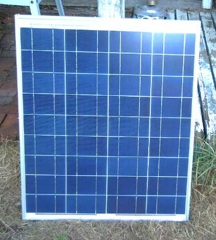
CTI-65 65 watt solar panel, a less popular model for 200$ discount
price at Home Energy in Vic West.
Tristan visited the day after I got the collector and he
thought a charge controller would be better than the linear regulator
and economical, so we went back to Home Energy and looked. (I had
thought they'd be too costly to consider and didn't bother to ask.)
There was one intended for lead-acid batteries, "SunSaver6" supplying
14.1 volts, 6 amps, for 42$. It had no adjustments, but I thought I
could make it work for the NiMH's. If I needed to charge the most
batteries at once, it would use the full 65 watts of the 224$ panel
instead of about 80% of it. Hmm... fart around with hacking a ready
made "best solution" for $42 or fart around for a longer time to make a
more lossy voltage regulator design of my own? I bought it.
266$ somehow got to be a ways off from my original
minimalist, low-cost intent: to scrounge or buy cheap an old solar
panel from my neighbor (who it seems is away for a month) or else find
a banged up or used one at Home Energy (weren't any), and cobble
together the 13.8 volt regulator (or a 6.4 volt one if I ended up with
one of my neighbor's 6V panels). And then mount it on my
high, steep roof, and wire it through to downstairs.
I put a schottky diode in to reduce the output voltage by
about .3 volts - from 14.1 to the ~13.8 volts the NiMH constant voltage
charge needs. (It turned out to be more like .4 volts drop. The system
tended to be a bit under voltage.) This however tricked the unit into
thinking no battery
was attached and it wouldn't turn on. I put a 1K resistor in parallel
with the diode so the battery voltage would appear on the terminal.
Somewhat to my surprise, this worked.
That didn't solve everything however - the batteries
continued to draw large currents even when they were well over 13.8
volts, as if the diode had no forward drop at all. It turned out that
the so-called "14.1 volts" consisted of short pulses of higher voltage,
merely averaging 14.1. I tried several capacitors to smooth out
these spikes and ended up with a large one, 4700uF @25v rating, across
the BATT output. That dropped the charge currents to the expected
levels. I feared that it might destroy the unit - at once or over time
- since it wasn't part of the design, but it has been operating fine. I
charged some batteries.
I noticed that the "14.1" volts drifted considerably with
temperature, from 14.06 (warm) to 14.17 (cool), which naturally
affected charging considerably. In the manual, it seemed this was
deliberate - must be something to do with lead-acid battery foibles. Oh
well!, it was still within essential limits. I also noticed that the
unit continued to work fine in the shade for the couple of watts still
being asked of it after the sun left the area.
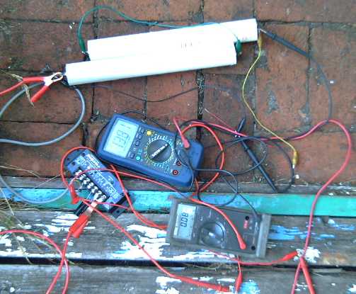
Testing and tweaking the 6 amp charge controller to charge two 6V NiMH
battery sticks
I used a 6 volt battery stick I'd charged (one of two in
series) to power my 6v LED lamp that evening, unplugging its regular
power adapter. Drawing an amp, it should have run up to about 9 hours.
I
would recharge the cells with the collector the next day.
That same day the August power bill arrived. It was 15%
lower than July's 30(?) year record low. (A big part is that I'm not
renting out any rooms now.) Unless I stop taking showers or doing
laundry,
it can probably only get a little lower now with more LED lights, but
now it bothers me to turn on high power lighting for any extended
periods. By October I'll be back to running electric heaters (and
burning wood), but summers - and all the lights on those long winter
nights - should now be almost free!
The next day I got the collector up on the roof (and
cleaned some gutters and the chimney while I was up there) and ran a
#12 wire down into the house - doubtless overkill but it's what I had
on
hand.
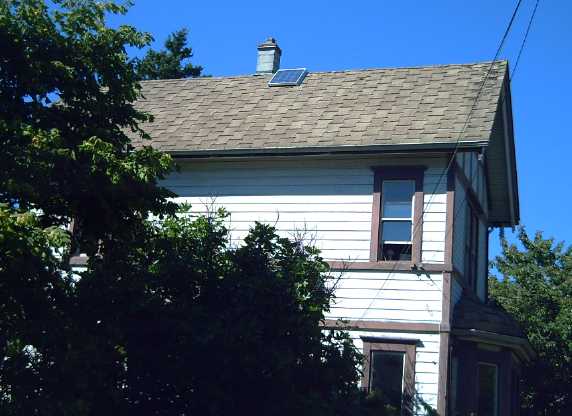
65 watt solar panel looking a bit lonely on the ideal 45º slope,
south
facing roof.
On further playing with the charge
controller and charging, I found that if maximum amps were needed, the
collector voltage was dragged down to the charging voltage. The
collector had good sun, and it should have had something like 17.5
volts and 3.7 amps input from the collector (65 watts) and 14.1 volts,
4.1 amps output (65 watts) - or less volts and more amps (still 65
watts) - but instead the collector was loaded to 12.5V and the output
was 12.4 volts at only 3.95 amps (47 watts). I could have saved my $42
- it was no more efficient and had no higher output than the linear
voltage regulator I had originally planned to make - and still might.
Solar to Grid Low Voltage DC Power Tie-In with NiMH Batteries
Tying a PV solar
system into the power grid is an enticing idea, but the investment is
high and the payback long, especially in our local cloudy-all-winter
climate. It has to be done in a big way (for an individual) to be worth
doing at all. 20 'full size' 225 watt panels at 500 $ and the grid tie
inverter, permits et al would doubtless run at least 15,000 $ and
probably more. That would produce only around 6-12 MWH/year or 600 to
1200 $/year at 10¢/KWH.
Short of that, is there some way to tie the
solar system and the grid together, even one-way only: to power LED
lights and any other
low voltage DC loads from solar power if it's available, but from the
grid if it isn't? That could save on the power bill even if that bill
could never be negative.
This would mean storing solar energy on site, which would
mean batteries. Here the NiMH batteries, or NiFe batteries, are key -
they have
it all over lead-acid. Lead-acid need to essentially be kept fully
charged or they deteriorate. It's a crappy chemistry for solar
power where the batteries are drained and recharged on a daily basis,
and may sit discharged overnight after using lights all evening. The
NiMH, or NiFe, can sit at most any state of charge and be drained and
charged random amounts, and they don't mind. The battery sticks make
the NiMH dry cells easy to make into higher voltage batteries.
So the solar panel charges the battery sticks. Then what?
Here's the idea:
1. I've been making LED lights of 3, 6 and 9 volts so far, but
unfortunately we have to pick one system voltage. Probably 12 volts is
the best choice - there are few solar PV panels with lower voltage.
Four lower current emitters can be used to make bright 12 volt lights.
Going higher means getting constant current drivers for the LED lights.
They're available, but I note there are many 12 volt LED lights
ready-made for campers, car and boats - far more choices than for any
other voltage or power supply.
2. The batteries are connected direct (but with fuses or breakers) to a
wiring bus that carries the power around the house to the desired
points for lighting. This wiring is probably the most labour intensive
item if it's to be done nicely. (Easy in a new house during
construction!)
3. A 13.8 volt power supply connects the collector to the batteries.
The power supply should be designed so that if there isn't any sun,
power won't go backwards from the batteries into the supply. (Note:
My collector has two diodes. If the power won't get back from the
batteries to the collector, they aren't needed - the voltage will be a
bit higher without them. Oh, no!, it's way up on the steep roof and the
wiring box with the diodes is underneath it!)
4. An 11.75 volt (rough estimate of best voltage) power supply comes
from the mains to the batteries. It also is designed so that power
won't go into it from the batteries on the load side if their voltage
is above 11.75 volts. As long as the battery voltage is above 11.75,
this
supply is at idle.
Now the solar collector supply puts up to 13.8 volts onto
the system if it's able to. (Of course, if the sun is shining, use of
lights will be minimal.) With the collector off, eg at night, the
batteries, with any reasonable load, will run at about 13 to 11.75
volts
from fully charged to almost 90% discharged. As long as they're above
11.75 volts, they'll supply
all the power. Once they drop too low, 11.75 volts will be supplied
from
the mains.
When the sun comes out, the batteries will recharge.
Once installed, this system
would be entirely automatic, nothing to do or to worry about.
Of course, with just my 65 watt panel, it's going to take
a couple of days to make 10¢ worth of electricity, or 3 dollars a
month. Around here, count on only about 6 productive months per year -
$18. To get my $224 back for the panel, even ignoring other costs and
any power going unused, will take 12 years.
But really the storage is the main problem with the
concept. 50 NiMH D cell batteries for 50 amp-hours/600 watt-hours, at
$7 each, would cost more than the collector ($350), and being
cycled daily, they might have to be replaced within ten years or even
five. (or just add 10 more at a time as needed - evidently only the
capacity drops, and after the rated 1000 charge cycles they still have
75% capacity.)
Now add more panels and batteries and get a 12 volt
fridge, make a solar hot water system and get a clothesline, and you're
pretty much off grid!
I think I'll leave all that out of my plans as the power
bill is already low. I may not make even the system described for the
65 watt panel.
The fact that more economical, super long
lasting batteries would make this system much more practical would
indicate that it would be better for me to put my energy, time and
inventive skills into creating
those batteries.
Just for effect tho, I've been charging a pair of 6V
battery sticks and using them to power the 2-emitter LED lamp in the
evenings. It runs 3 or 4 hours, tho gradually dimming as the current
drops from an initial 1.35 amps to .5 amps, as the cells drop from
about 6.5 volts to 5.9 volts. The voltage drop is a little faster than
expected and the lamp is very sensitive to voltage changes.
http://www.TurquoiseEnergy.com
Victoria BC