Turquoise
Energy Ltd. News #44
Victoria BC
Copyright 2011 Craig Carmichael - October 1st 2011
http://www.TurquoiseEnergy.com
= http://www.ElectricHubcap.com
= http://www.ElectricWeel.com
New Product: Handy Battery Sticks, Quintos
Battery Sticks
* nickel-metal hydride dry cells in plastic tubes: 6 or 12V, 10 AH, 30+
Amps, 1000+ recharges, lightweight (See NiMH Battery Project article).
Month
In Brief
(Summaries)
- The Projects
- Washing Machines: Another example of vested interests blocking
environmentally valuable progress
- Solar Photovoltaic Panels Versus Site C Dam: cheaper, more flexible,
less land use?
- A better idea for wind power?: windplants strung between mountains
on 'cable car' cables.
Electric Hubcap System
* More reliable connections to bus wires in motor controller?
Electric Weel Motor
* Doubled the skins on the plywood stator rings - waited for the
epoxy
to set on both sides of one ring... I used hardener (honest!) but
after a week, still gooey! Added another layer of PP epoxy on each side
- finally it all hardened.
Mechanical Torque Converter Project
* Some converter construction work done (drum bought, slotted,
other parts found).
Sprint Car
Conversion Project
* Trouble at the pass - back to original plan! no, ditch 135
pound
transmission! no, keep it!
* Fresh Start (long story short): the differential by
itself from the transmission is lossless - perfect!
* ...driven with 3 to 1 reduction motorcycle chain drive
(sprocket gears found and fitted)...
* ...and mechanical torque converter on motor, which now has a 3x
easier job than direct-to-wheel converter.
* Fitting and installing drivetrain component housings &
mountings.
* Converting gas pedal to electron pedal
* Front brake disk repair... and a simple way to measure the
torque needed to move the car.
* A thought: it's suddenly morfed from a "typical"
car conversion project into a highly efficient "cutting edge" one!
NiMH
Battery Project
* Batteries for "mobility scooters" - or - "Electric Transport
101 Practical
Lab".
* Short "quintos' battery stick sets to fit in lead-acid battery
boxes, spaces.
LED Lighting
Project
* LED automotive lighting: off the shelf 12 volt lighting for RV,
boat, solar home and other 12V DC systems.
* Plastic diffusers ordered - plastic food containers as
diffusers.
Turquoise Battery Project
* Tried a couple of electrolytes
* tried zinc negative (zinc sheet
from a dry cell, zinc oxide powder).
* Eliminating dishsoap from negatrode reduces self discharge?
* Still poor conductivity
Newsletters
Index/Highlights:
http://www.TurquoiseEnergy.com/news/index.html
Construction Manuals and information:
-
Electric Hubcap Motor
- Turquoise Motor Controller
- 36 Volt Electric
Fan-Heater
- Nanocrystalline glass to enhance Solar
Cell performance
Products:
- Electric
Hubcap Motor Kits, Parts - Build your own ultra-efficient 5 KW
motor!
- Sodium Sulfate
4x
longevity additive & "worn
out" battery renewal.
- Handy Battery Sticks: NiMH D cell batteries:
6V (14") -- 12V (26") or Quintos 12V (5 tubes @ 7")
- NiMH individual Dry Cells (D - 10 AH, $10 -- AA - 2.5 AH,
$2.50)
- Motor Building
Workshops
...all at: http://www.TurquoiseEnergy.com/
(orders: e-mail craig@saers.com)
September in Brief
Tho the
month had a heavy emphasis on the Sprint electric car conversion (I got
some job or other done on it almost
every day), I also tried to do at
least something on each main project.
I started in on the torque converter for the Sprint and
made the output rotor. I had everything pretty much figured out by the
6th except the details of the sprung wedges and their mountings on the
input rotor, then I set it aside to work on other things. At that
point, I wasn't sure I was going to use it in the Sprint.
Some epoxying over 3 days got the Sprint motor almost
ready to assemble, and also a second layer of PP cloth-epoxy on the
Weel motor parts. However, work on both motors then came to a stop with
too many things to do. I decided to use the existing motor, intended to
be for the outboard, in the car.
Concurrently, someone had contacted me about
wheelchair-scooter batteries, and I made some "Quintos" ("fifths") 12
volt battery sticks to
fit into Pb battery boxes. The 6 MPH scooters ran great with a single
bank of NiMH batteries (10 pounds), which seemingly might yield a range
somewhat
under 2
hours time and 10 miles distance, as they drew about 5 amps on level
ground. The PbPb batteries weighed 50 pounds
and supposedly offered 11 miles. Three banks of NiMH sticks fit in the
battery
boxes (total 30 pounds) and should "theoretically" take it about 30
miles (on level
ground). The scooters proved to
be a good "Electric Transportation Principles 101 Lab Exercise". They
drew about 5 amps on level ground, increasing to 10, 15 or 20 amps
going up hills, and down to 2, 0 or even -2 amps going down hills. The
real range, with slopes and all, proved to be far less than the
theoretical. Hills were killers - brief periods of -2 amps going full
speed downhill in no way made up for the 15-20 amps for much longer
periods to go up the same hill at a crawl. I concluded that mobility
scooters, at least these ones, had to be about the most inefficient
electric transport possible.
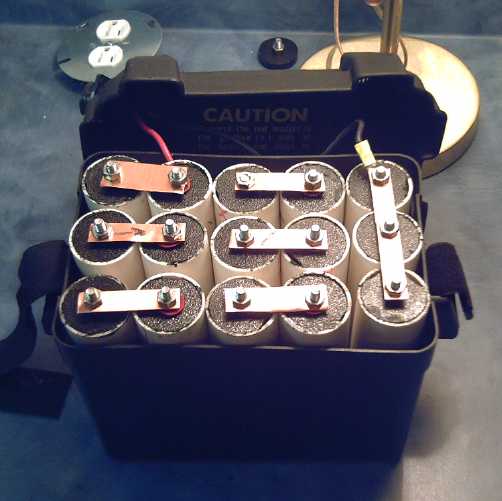
Quintos "Handy Battery Sticks" - here 12 volts, 30 amp-hours, 15 pounds,
easily reconfigured to 36 volts, 10 amp-hours.
The next problem was charging the NiMHs for scooters.
Unlike the lucky hit
with the 13.8 volts car charging systems being ideal for NiMH car
batteries, plug-in Pb battery chargers generally want to pump
current into them until they hit 28.8 (2 x 14.4) volts - effectively
meaning until they fail or burst, since they simply won't go over about
28.4.
And there were internal chargers and external chargers, each with its
own scheme of the best way to charge PbPb batteries and knowing of no
other kind. I designed two circuits to take a PbPb charger supply and
feed it to NiMHs, but I don't really have a product to sell at this
point.
With my successes running
mobility scooters with NiMH battery sticks, towards
the end of the month I did a little sales trip to several mobility
scooter places and a stairway lift place. But warranties and lead-acid
battery
contracts with scooter manufacturers, uncertainty about chargers and
charging, the high initial cost
of the NiMH battery sticks (the
increased cell prices this summer
hurt), and plain unwillingness to try something new, prejudiced even desire to try them out.
Green, very long life car batteries is still the most promising market,
but I'm not exactly making a breakthrough there either.
The Sprint conversion by
hooking an Electric Hubcap up to
the original transmission seemed to run into a snag, with the reduction
seemingly insufficient that the motor would move the car, and from
having
thought I knew what to do, I went back to considering options. But
the mobility scooters, and an e-mail, suggested a grand solution. Ditch
the lossy automotive transmission, put a lossless mobility scooter
differential by the motor: on the high speed, low torque side of
the drive, it would be big enough. Then use dual chain drives for
the
speed reduction from the differential to the CV driveshafts driving the
wheels.
When I removed the transmission, I found the 'insufficient
reduction' was an illusion created by a centrifugal clutch inside. But
I wasn't putting it back in. Had I known more, I'd probably have just
done the regular conversion and got the
car running. Instead, it's en route to a highly efficient
drivetrain system instead of the lossy, heavy automotive
transmission... I hope.
The mechanical torque converter is to play its
part, and this project may point to a new way of mounting them on car
wheels: first the torque converter, then a further reduction by
planetary gear. That divides the load on the converter and the amount
of torque increase needed from it by about three.
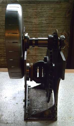
Making drivetrain housing for Sprint:
torque converter drum at left, differential below & behind.
I put another layer
of PP fabric-epoxy on one of the Weel
motor stator pieces after the first one was still gooey after 10 days
or so. It's just about ready to put together once I coat the
coils, tho I should work out the bearing mounts and the magnet sensor
board.
One day I glued and duct sealed the box for my own
chemistry
battery back together after it broke about two months ago, and tried
potassium chlorochromate and then potassium perchlorate as
electrolytes. Neither seemed to help. The low conductivity
problem appears to be the last hurdle to developing cheap, green, very
high energy
density batteries. Why is the conductivity so low? - what's missing?
Then I scraped out the negatrode and put in a sheet of
zinc from a dry cell I took apart. That charged to 2 volts. The
cell didn't conduct any better, tho it improved with each cycle over a
few days. I've had better results with my own chemicals. Next I'll make
a new non-cracked box and
try the manganese side from a dry cell as well as the zinc, and have
what
ought to be chemically a regular dry cell. If that doesn't deliver...
what's wrong?
On the 30th I put together a very bright LED light for the
shop (32 volts - a bit of a messy setup), after making a bright lamp
(13 watts, 12 volts) earlier (that I've mostly been running off a Handy
Battery Stick charged by the solar collector). 18 watts for the main
light instead of 150-200!
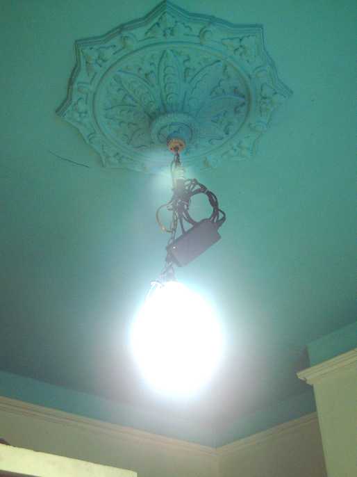
18 W LED Machine Shop Light
Yet Another Vested Interest Blocks Progress - needless
pollution continues
I point at vested interests (led by big oil) blocking progress in
electric
transportation, but dirty tricks and impenetrable barricades thwarting
progress are endemic to our society with the preposterous patent system
and
the so-called "capitalist" dog-eat-dog system. This month someone
related to me this
story: Someone invented a new type of washing machine. Instead of
agitating the laundry, it used air bubbles and caused the water to
vibrate at a high frequency - an ultrasonic washing machine. It
worked well: clothes came out cleaner - even without detergent -
and they would last longer owing to less wear-and-tear during washing.
There was less fluff in the dryer because the laundry had had less
stress
in the washer. It doubtless made
the news back when it was invented.
The invention was duly
patented, and detergent companies duly acquired the threatening patent
to
suppress it, a legal bludgeon to prevent anyone, anywhere from making
machines that could
clean without detergent. A quick web search disclosed a patent for such
a machine, filed in
1985 - United States Patent 4727734. As usual, by the time the patent
expired, virtually no one would
remember the invention. If anyone should think of it at all today, they
would
think the idea must have been a failure since no one has ever
manufactured them. This month (September) marks 26 years since the
patent application: a quarter of a century that we've been needlessly
taxing sewage treatment systems with laundry detergent chemicals and
having our clothes wear out earlier.
It should be an
easier machine to build than present types of machines, because all the
basket has to do is spin out the water (assuming even that's still
necessary): no complex mechanism for a back
and forth agitation cycle.
If you decide to patent your invention, consider that
wealthy vested interests routinely monitor all patent applications, and
if your invention in any way threatens such interests, they'll bring
great pressure to bear - some have very deep pockets and will stop at
nothing trying to prevent or delay change. Patenting a world-changing
invention is a great way to ensure it never becomes available to the
public and falls by the wayside.
It can indeed be discouraging to see the cold, cynical way
that vested interests prevent progress - and are permitted to prevent
progress - in our society. Patent reform and Departments of Progress in
governments
would help bring this odious house of cards tumbling down.
Solar Panels Versus Site C Dam: Lower cost?, less land?
Recent figures for the Peace River Site C Dam are: 1.1 GW
maximum capacity (up from .9 GW in 2006), 5.1 TWH of electricity per
year (up from 4.6), and 7.9 billion dollars to build (up from 5 to 6).
I'm suspicious that the river should now be able to produce more
electricity now than it could a few years ago, and also that the actual
cost may be well over 10 billion dollars by the time it's done. The
cost of the transmission lines to get this power to the grid from this
distant wilderness is also in the billions of dollars (2B$?), and the
power losses en-route will be substantial. But I don't have time to
delve into the publications to seek further details, which may (or may
not) explain the discrepancies.
How much would that amount of electricity cost with solar
photovoltaic panels? The lowest retail cost of solar panels I've seen
is about 300 $ for 225 watt panels. That's 1.33 $/W. Assume BC Hydro
could get quality panels for that bulk price. (Maybe even Canadian ones
- a
major solar panel brand is produced in Canada!) To make up the 1.1 GW
generating capacity, the panels would cost just under 1.5 billion
dollars. Assume that installing them and connecting them would cost
just as much per panel. That would be 3 billion dollars for 1.1 GW
capacity.
But the sun doesn't shine all the time. Assume
installations were placed in (eg) the sunny Okanagan, and that they got
240 sunny days a year (2/3 of the days). With the sun shining at
different angles, etc, assume 9 hours of 'direct' sunlight, which would
actually be spread out over the length of each day averaging 12 hours.
That's 1.1 GW * 9 Hr/Day * 240 Day/Yr = 2.4 TWH/Yr. So the 3 billion
dollars buys just under half the annual electricity of the dam.
Multiplying it out, 5.1 TWH / 2.4 TWH * 3 B$ = 6.4 B$.
That's 1-1/2 billion dollars less than the current price given for Site
C (a 20% saving), with over double the actual generating capacity
(2.1 GW) during the day. It would also produce the most power during
the summer, somewhat complementing river hydro where the winter rains
bring the power and water has to be carefully saved in summer and early
fall.
One wild card I'm not taking into account is snowfall
covering the collectors. Snow falls in winter when the least sunlight
is available, but it might be a notable factor in site selection. A
certain amount of snow will slide off 45º sloped collectors if the
bottoms are up off the ground. (If they can be pivoted, they could be
tipped up to vertical to dump snow off - but I'm assuming fixed
mountings for simplicity and reliability.)
Now, Site C is expected to flood 93 square kilometers of northern land. Using
2.1 GW capacity and 15% panel efficiency, and 1 KW/m2 for
sunlight
energy, we find the panels must occupy at least 14 square kilometers of
arid countryside. It is likely to be substantially larger to account
for sun angles, service access, etc. Call it 28 square kilometers.
This, less than 1/3 the land area of site C, can of course easily be
split into any number of smaller parcels with the same total area. And
smaller installations could come on-line as soon as they are built
rather than being an all-or-nothing proposition: with Site C, all the
eggs are in one basket. And the sites could be selected to be near
existing transmission facilities, which would eliminate the additional
cost of the new line from the distant reaches of the Peace river.
And, while the estimated cost for the dam can only be
expected to
rise, the price of solar panels is dropping year by year. By the time
the 10... 11... 12... 13 billion(?) dollar dam and transmission lines
are switched on,
doing it with solar panels might have dropped to 6 billion or less,
and the earlier installations would have already been making
electricity for some years.
Obviously my figures would need detailed examination,
but these
estimates seem to me show the essential proportions, and unlike my 3
billion dollars capital cost estimate (2008) for 900 MW & 6+
TWH/year of west coast
wave power, solar is known, proven technology that can be purchased
'off the shelf'. Would it work any the worse for being scaled up to 2.1
GW capacity?
Any renewable energy installation including Site C is of
course far
preferable to coal, making a nuclear power plant is now absurd, and one
should consider carefully
before switching horses in mid
stream. But no one is going to ante up several billion dollars for
energy supply except government, and it appears to me that the BC
government should re-examine the Site C dam project in the light of
rising cost estimates for it versus the dropping costs of solar energy.
Here are two other interesting things to consider as
alternatives to the dam that I don't have the requisites at hand to
attempt to calculate cost or other figures for:
1. A project price for equivalent wind power - perhaps incorporating
the idea below, which could possibly make wind power more effective and
attractive.
2. The amount of electricity that would be saved if most people in BC
could switch to LED lighting - including streetlights, schools, office
buildings, and so on. This might be difficult to estimate, but would
doubtless be very substantial. Across BC, could it save the whole
amount of
electricity to be provided by Site C? If so, how much would it cost -
more or less than the 10 billion dollars for the dam plus transmission
line costs? Surely it must be worth doing!
Here's an idea for wind power: Generally the higher the
plants are off the ground, the stronger the winds. Winds are also often
strong in mountainous areas (partly since the mountains are above other
ground). A unique way to gain elevation in mountainous areas might be
to string heavy cables across a valley between two mountains. The
windplants would be spaced along the cable like cable cars, with a
similar winch assembly to wind them in and out for servicing. This
would get the propellers very far above ground, not only capturing much
more wind, but probably also (though I'm no authority) placing them far
above most bird flight paths and well away from dwellings. An
additional feature could be that if the plants were hung from a single
cable and the dimensions and weight considered, they could swing up
towards horizontal in high winds to angle the prop and inherently
prevent overloading. This could simplify construction.
Some calculations might well show that this would be more
cost effective than ground tower based installations - cheaper per unit
and each unit gathering substantially more wind energy.
One place that already has cables strung at relatively
high elevations are high power lines. One might also envision
windplants either strung from the same wires, or (if that's impractical
- those are VERY high voltages) from a second set of wires underneath.
Again these wires might be like a clothesline and the windplants could
be reeled in and out to and from the operating tower for deployment and
maintenance. Perhaps those long power lines from the Site C dam might
make more power than the dam?
Electric Hubcap Motor System
Somehow
this month most of the 'system' things seem to be under other article titles:
- Weel Motor
- Mechanical Torque Converter
- NiMH: Handy battery sticks: quintos (5ths) cases and tests with
mobility scooters.
- Car installation: Sprint Car Conversion project
Motor Controller: Bus Wire Clamps
Since a solder joint from the sense wire to the MOSFET
return bus broke and the motor controller fried, I've been wanting
a better way make that connection, also the fuses-to-B+ bus connection.
For the fuses, I made a clamp.
I'm only marginally satisfied with that too. I'd rather
mount the fuses bus on the chassis somehow and have a wire to the B+
bus.
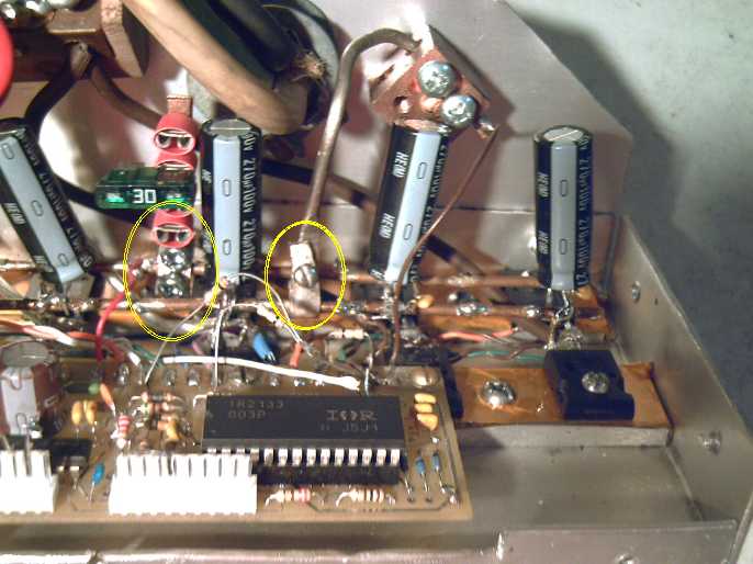
Bus wire clamps were made by flattening nickel-brass wire, drilling it
and tapping it for machine screws.
The nickel-brass wire that is the ground current sense
resistor was thinner. I flattened it and then looped it around to form
a clamp with a single #4 bolt. It won't break away from the MOSFETs
source bus like the solder joint did, but I envision some sort of more
scucum clamps, perhaps not as heavy as the main copper grounding block
on the back wall... then again...
But as of the end of September, the controller is repaired
(changed 10 of the 12 MOSFETs and the IR2133) but hasn't been tested
yet. Another controller needs to be made, and I'll use up the other
"version 1" board before I get any "V2" boards done.
I'm starting to think it might be nice to do a
microcontroller based motor controller - it actually cuts down on the
number of passive components, and allows more flexibility for various
options. I'll probably get some version 2 boards made anyway as it'll
be some time before I'll find time to do such a design.
Electric Weel Motor
Continuing the long, lethargic saga of the 15 KW, 17"
diameter x 4.5" thick Weel motor, I
put another couple layers of unwoven PP fabric on the
plywood rings because they seemed pretty flimsy. The epoxy on one ring
refused to harden. I don't know what happened. I did
add hardener, but I probably didn't mix it too thoroughly before I
started painting. After about 10 days I decided they weren't going to
set,
and epoxied another layer of fabric on each side. This appeared to
solve the problem, and added more (by no means unwelcome) stiffness.
Then I bolted the base of the stator together.
Mechanical Torque Converter Project
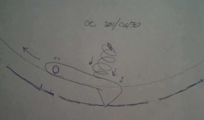
Torque converter active elements, concept as of June 30th 2011.
Wedges on sprung arms spin with the input rotor (inner),
bumping into slots in the rim of the output rotor (outer).
All wedges strike a slot at the same time, creating the maximum tug on
the output.
At the start of the month, I started in
on the torque converter for the Sprint, and it became rather mixed up
with the Sprint Car Conversion Project, next article
down. I cut an "SDS" size center hole
in the center of the output drum (a 10" diameter aluminum saucepan, cut
down to 2" tall),
and filed it out as near to dead center as I could. Then I cut 30
equidistant slots in the
rim. There were some nasty flashings around the slots, and I used a
sharp chisel to not only remove them, but bevel the edges of the slots
to 45º. Now the plastic(?) wedges won't hit any sharp corners, and
the slots are in effect widened considerably. That was good since I
thought perhaps .05" (angle grinder zip cutter disk thickness and
hacksaw blade thickness) was a bit narrow even for 'narrow' slots. The
slots are about an inch wide (leaving 1/2" solid edges around the 2"
wide pan rim), and I plan to use 3/4" wide wedges.
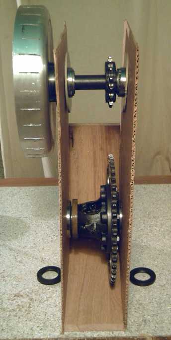
Torque converter drum on Sprint car drivetrain.
(Later it was decided to place the converter between the mounting walls
near the gears,
with the motor where the converter is in this picture.)
Disregarding frictional drag of plastic sliding on greased
aluminum, all the torque is developed as the wedges traverse the last
half of their respective slots, recompressing their springs. The wedges
are about 3mm wide and it's 27mm between slots. If the coupling is good
and the motor is loaded down (rather than simply rising to its maximum
RPM without driving the output drum to full strength), the torque gain
is thus 27mm (total) / 1.5mm (torque area) = 18. But it all depends on
the relative RPM speeds, the actual speeds, and the coupling between
the input wedges and output slots.
What happens if only 2x torque gain is needed? One reasons
that if the torque gain is 2x, the speed reduction must also be 2x,
with the motor going twice as fast as the output. The slots and wedges
at
18 to 1 may represent the maximum possible torque increase... but even
that probably varies with the coupling. More wedges increases it, so do
stronger springs. If the coupling is too light, it may not get anywhere
near that figure, and if it's too heavy, the motor will get stuck in a
slot and won't be able to start turning. Hopefully there's sufficient
middle ground between these two points. If not, weaker springs and more
mass in the wedge arms would increase coupling by centrifugal action
without loading the motor as much at low speeds. But in that case the
slots might need to be widened to allow the centrifugal force to have
more effect.
After ordering
a 7/8" shaft SDS bushing to mount this drum on the transmission
input shaft, I
found I actually had everything else I needed except 3/4" thick
plastic. Maybe I'll use 1/2" for the first try.
I had a 1/4" thick, 9.7" diameter flat rotor for the input
rotor (it was previously the very first Electric Hubcap magnet rotor).
It just
fit inside the
drum. The center hole was too large, but it would bolt to my car wheel
'flexible coupling' flange, which had the right inner diameter for
the 1" SDS I also already had. That saved me from having to get another
rotor cut by waterjet. Slightly hodge-podge, but workable.
I didn't trust the soft aluminum pan to properly compress
the hard steel SDS bushing onto the transmission shaft so it wouldn't
slip. So I turned out the center of a big washer to the SDS diameter
and drilled holes in it for the three bolts. That pretty much took care
of the output rotor.
The next challenge was to install a bearing
between input and output so it would hold the motor and transmission
shafts in alignment but allow them to turn at different speeds. The
motor side
was
trivial: leave 1/2" extra shaft to slip the bearing over. The other
side involved putting the SDS coupling on the lathe and hollowing out a
tenon dead center for the outside of the bearing cup. To get a good
alignment, the coupling had to be compressed onto a short length of
shaft during turning.
That would form the main structure, leaving the working bits to
be
figured out: the spring-loaded wedges to strike the slots in the rim,
and their mountings on the face of the input rotor. The wedges have
endless possibilities for adjustment:
- the number of wedges
- the shape and size of the arms
- the strength of the springs
- the mass of the arm acting on the wedge (centrifugal)
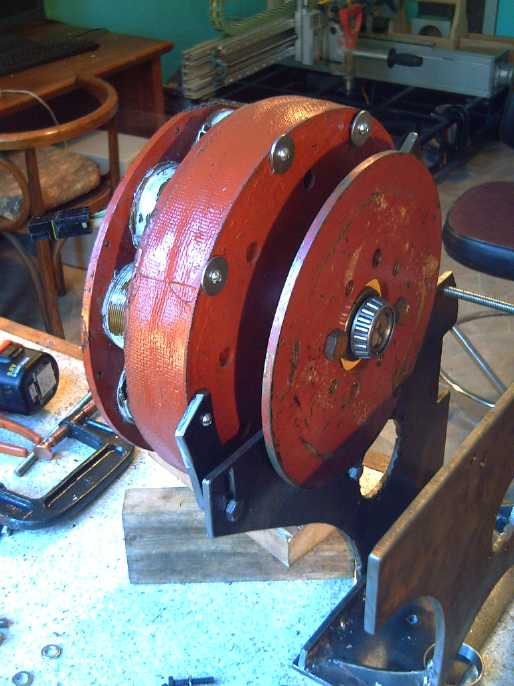
Input rotor on motor shaft. This is where the wedges will mount.
Output drum wraps around this.
The bearing on the outer end of the input shaft mounts the inner end of
the output shaft,
which is turned at a lower speed with a higher torque by the drum.
If the idea and the
actual construction both worked right, I would (finally!) have a
mechanical torque converter.
When the SDS bushing came, it proved a touch too big, and
also I was getting nervous about using a compression bushing on a
splined shaft. But in the end I changed everything. I ditched the
whole transmission, extracting the final differential gear and bearings
assembly from it, and made a 4 to 1 chain drive system with the torque
converter driving the small sprocket gear. The large gear mounted on
and turned the differential, now mounted 'externally' to turn the CV
drive
shafts.
With this arrangement, if the torque converter produces
even a
2.5 or 3 times increase in torque, that'll be 10 to 1 or 12 to 1 at
the differential and the wheels, and
the car should go. Furthermore, the forces on the converter as
a whole, though 4 times faster in speed, will be 4 times lighter. Any
sort
of converter certainly has a better chance of successful operation in
this lower-stress, lower need environment than going straight to a
wheel. In fact, once the chain drive and MTC output drum are
mounted, I expect to be able to crank the torque converter drum
around by
hand and have the car move.
Once it's working, I expect to be able to change the chain
drive from 4 to 1 to 3 to 1 or less to increase the top speed of the
car. Then the technique can be duplicated for a wheel
mounted motor: the torque converter, then the 2.8 to 1 planetary gear
instead of the chain drive. That would add maybe an inch or more
of thickness to the system - probably still not too much for mounting
on the
outside of a wheel, but getting up there.
Sprint Car Conversion Project
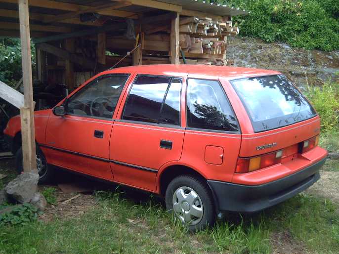
A smaller, lightweight car to convert to electric
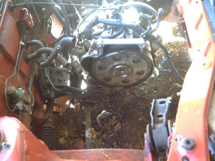
Sprint transmission with engine removed. Use or discard, use or discard?
New "ultra-efficient" drivetrain plan with lossless differential and
flexible reduction chain drive settled its fate.
Fitting the Motor: Ditch the tranny?
- or not?
Originally, I thought I could just attach the motor to the
original transmission as-is. This was true, but at a time of decision
the automatic transmission constituted a confusion factor that changed
the plan. I was ready to accept the 40% lossiness of
a typical automotive automatic transmission in exchange for a quick
conversion project to make a city only vehicle. But after previous
experiences, on turning a wheel
it looked
like the gear ratios wouldn't be enough reduction even in first gear. On the
other hand, the
torque of the Sprint engine was supposed to be 61 foot-pounds, or 57 at
3200 RPM, or 73, depending where you look. That's four times the
Electric Hubcap -- but that's maximum, with the engine roaring away.
Generally
one starts rolling with just a little gas. Did that mean 16 foot-pounds
should be enough to get it moving? or not?
Then I thought I had a plan figured out to fit the motor
and a mechanical torque converter, or a planetary gear, onto the
transmission. I ordered an SDS bushing, but it didn't quite fit onto
the transmission's input
shaft - the inner diameter was a bit too large. I also became a little
uneasy about the idea of putting a taper lock bushing on a spline shaft.
Then I had the thought
that perhaps the CV drive shafts might have the socket for the same
spline shaft - after all, it's the same car. And the spline socket was
what it was supposed to have. Unfortunately the
Chilton's repair manual was vague on such vital details. Especially,
after 5 chapters on the (discarded) engine, it hardy touched the
transmission. "Take it to a specialist" it said, and showed no details.
The best, if not terribly convenient, way to check out the
spline size seemed to be to take a wheel off and try it. I had a really
hard time trying to get the center nut off, and finally gave up. (I got
it off later, but only after wetting it well with brake fluid for a
couple of days, and then buying the exact 30mm hex socket. Soon - and
thinking of the truck to come - I bought an air wrench for the
next problem.)
Instead, I bought a Sprint wheel at an auto wrecker. This proved pricey
and the spline didn't fit - it was just a little bigger. Oh well, the
right front wheel needs the brake disk that came with it. What a way to
get a brake disk!
It seemed the project was turning into an expensive
boondoggle. On the other hand... if the transmission only had 3 to 1
reduction as it seemed, well, my loose planetary gear sets had 2.8 to
1 -- almost the same. Both planetary gears together would be almost 8
to
1. What was the value of the transmission then, except as a mounting
and to have the differential?
Even though it would only drive one wheel, either CV shaft
could be driven through:
1. a planetary gear (2.8 to 1 reduction and poor prospects for moving
the car.)
2. both planetary gears in series (7.8 to 1 and pretty good prospects,
but top
speed would be quite limited.)
3. the mechanical torque converter alone (dubious prospects.)
4. the torque converter and then a planetary gear (good prospects.)
5. the torque converter and both planetary gears (excellent prospects,
but it probably wouldn't go very fast.)
So why was I keeping the transmission? It appeared to be
50-75 extra
pounds doing not much except providing a differential. But while a lone
rear wheel might well be driven, I didn't really fancy the idea of
driving a single front wheel. If I'd found a five-speed manual, I'd've
simply connected the motor
and hoped for the best. Now instead, was I
back to trying to drive a wheel without a transmission? I thought I got
this car to have a ready-made drivetrain!
Some things were
puzzling tho - when I
turned the wheel, the transmission shaft turned and appeared to have a
3 to
1 ratio... But that was with the stick in any gear position (except
Park), and, if I turned the
transmission shaft, the wheel didn't turn at all. A curse on automatic
transmissions! What's really happening? What is the actual
ratio? Perhaps, after all, should I try putting the motor right on the
transmission with the original fluid converter and see what happens?
I'd think 16 foot-pounds of torque sounds
good enough to get rolling if the gas engine only made about 60
max when roaring away. So I decided to go with the original
plan: the original
transmission and the fluid torque converter, and see what happened.
That had the advantages of being much the simplest to try out and of
not doing anything irreversible. If it worked, I could perhaps try
trading the fluid converter in for the
mechanical one.
If it didn't work, I could then consider the next thing
to try.
Aha! Fresh Start
But then I had a brand new idea. On a chain drive mobility
scooter differential, everything turned in unison when traveling
straight. Essentially it had no moving parts except when the scooter
was turning left or right, so in effect it was lossless except for the
chain drive input itself. It seemed to me this was a far cry from a
lossy automotive differential with a right-angle shaft change gear! It
looked too puny for a car. Then
again, what if it was hooked up at the motor, before the speed
reduction to the wheels? In the higher speed, lower torque side of the
drivetrain, it should be big enough. The chain input suggested also
using a chain drive output to the CV shafts. And this month a
newsletter reader mentioned someone else converting a Sprint and using
chain drives. Maybe chains wasn't a silly idea for a car drive after
all. I looked into motorcycle sprocket gears and chain, and industrial
equipment ones. It seemed that:
- various matching chains and sprockets could be had, though the speed
reductions available generally weren't much above 4 to 1. The larger
reduction needed would have to be done in two steps.
- Chain "pitches" suggested by the motorcycle shop were Japanese sizes
428 (lighter) and 520 (suggested as a "good size" for the car
application), and 530, which matched American industrial size "50
pitch".
- the industrial sprockets would be cheaper, and easier to mount on
machine shafts.
- but that motorcycle chains should be used, as industrial type chain
would wear out quickly if used at high shaft speeds.
It seemed that could be made to work, and reduction ratios
could be played with at will, since changing a sprocket gear is pretty
simple. This seemed to be the best way to go. The heavy, lossy,
automotive transmission would be turfed out after all, and replaced
with a light, highly efficient drive system using chains, sprocket
gears and the scooter differential. The bearings and chains would just
need to be oiled or greased once in a while, where the oil filled
transmission can (and usually does) go for years with no attention at
all. Worth it.
The mechanics would be:
- motor turns scooter differential unit, via a 2 or 2.5 to 1 speed
reduction chain drive.
- final 3 to 1 speed reduction would be with two heavy chain drives:
one from each side of the differential to each of the two CV drive
axles. Since the tension on each chain would be balanced, they could be
smaller than with a single chain for both sides, hence there would be
little performance penalty for 'differentiating' early.
Total speed reduction would thus be 6 to 1 or 7.5 to 1. If it had to be
even higher, or if it could be made lower... and to try out mechanical
torque converters... this would be an easy system to make such changes
to.
That was the moving parts... mountings, bearings et al
will
have to be made up and fitted on to hold them in place to create a
working system.
The motor shaft is 1". A sprocket with 20 teeth matching
those of the differential's 40 tooth sprocket - whatever it was - would
give 2 to 1 reduction. 16 teeth would be 2.5 to 1. Hopefully I could
find out the type of chain if I took it in somewhere, and the right
gear and coupling would be available.
On the 14th I pulled out the transmission. I had purchased
an electric winch just to see how it got 80 to 1 gear reduction some
months ago, and when I got the Sprint, I mounted it in the ceiling of
the "carport". It proved itself priceless. I just took out a handy
battery stick when I wanted to use it, and there was no shortage of
power. (At one point taking out the engine, it got stuck, and the
ceiling was bowing down dangerously as the winch happily tried to lift
the
whole car.) I was also glad I used it to lift the transmission.
When I weighed it I was astonished. I thought it might be
60 or 80 pounds, but it was
in fact 120. The fluid torque converter was another 16, total 136. The
transmission was as heavy as the engine that drove it! Good as the
early Sprints are on gas, the weight of an extra "passenger" alone must
certainly have cost a few miles per gallon, never mind all the actual
transmission losses. No doubt it's heavier than the 5-speed manual
transmission. By the time I've got the fuel tank, gas pump and a few
other odds and sods out, the car'll have shed about 400 pounds. If we say then that the car (automatic)
weighed 1750 pounds instead of 1700 (5-speed), then if I add 200 pounds for the
electric drive (over 1/2 of that being the puny 3 KWH of NiMH
batteries), it'll be around a trim 1550 pounds or so.
While I was working on the transmission, I got the price
quote for the Martin sprocket gears: 54 $ for the 15 tooth and 161 $
for the 45 tooth. So much for the "industrial" ones being cheaper. Two
sets would be well over 1/2 the price of the whole car! Being on a
budget, I decided to check out used motorcycle gears first. The
"motorcycle wreckers" would be open on the 16th and 17th, 10 AM til 2
PM. I did, however, need to find pairs, preferably that would be simple
to mount. And one for going from the motor to the differential, or
selections from (say) 12 to 25 teeth for different ratios.
The next day, I took apart the transmission. Now I began
to see what I hadn't known before. There appeared to be a centrifugal
clutch that only engaged the gears when the engine was running fast
enough. If I'd known that, perhaps I could have have ditched the fluid
torque
converter and hooked the motor straight to the transmission. And that's
why I'd had odd results trying to check the gear ratios - it
wasn't engaged. I now found that it seemed to have maybe 12 to 1
reduction in first gear - my motor would have turned that.
Everything would have worked out fine! But I wasn't about to put it
back in.
Other parts of the conversion & a way to measure torque at the
wheels
At some point, I dropped the knotty problem of the
drivetrain and started taking more bits off the car - the gas pedal
cables, heater hoses, gearshift lever and cable... Then I unscrewed the
gas pedal and took it in the house to install a potentiometer to turn
it into an "electron pedal". These details had to be attended to some
time. What better time than when I was considering what came next on
the
main challenge?
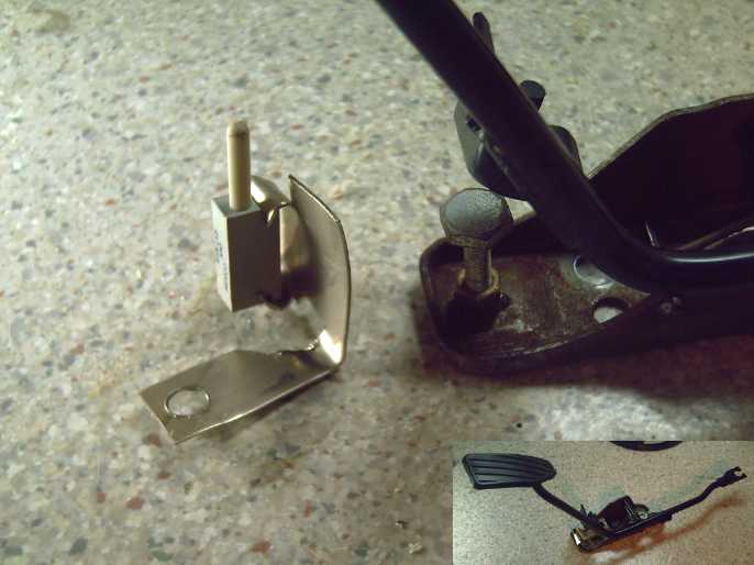
Fitting 'electron pedal' with plunger style linear potentiometer
Under a flat piece on the pedal in an
area with about the right amount
of travel seemed like a good place to put the pot.
I cut out and bent
up a piece of
nickel-brass to mount it on.
After a lot of finnicky trimming, filing and
bending, it was a
perfect fit:
it hits pretty much square, there's just a fraction of play before the
pedal touches the pot
plunger,
and I adjusted the bottom stop to hit just before the plunger
hit its end.
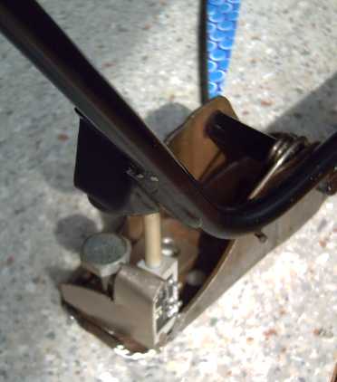
To finish the story, on the 23rd I got a 3 pin trailer
lights plug and socket and wired the "electron pedal", and installed
it, adding a second return spring to replace the carburetor's. The
internal spring brought the pedal up, but it was so weak I couldn't
feel the pedal with my foot. It still wasn't as strong as I wanted -
you have to hold your foot up more than press it down - but it'll do
for the time being.
Then there's the really mundane parts of converting an old
car... on this car, you
have to take the wheel hub off to change the brake disk (?#!$%*!). The
one on the car was toast and early in the month I'd taken off the
wheel. I
now took apart the wheel I got from the auto wreckers - no easy task -
cleaned up its brake disk on the belt sander, repaired the front right
wheel, and (at last) set the car resting on the ground on four tires
again.
But this led to a good test. When I did up the wheel nut
it was with a torque wrench... say, that was trying to turn the wheel!
I found that to get the car to climb out of the depression the tires
had made in the ground took
just over 100 foot-pounds of torque. Cool! - a way to measure the
actual
torque needed to move the car! At four to one ratio with the chain
drive, the motor would need to supply 25 foot-pounds. It probably has
around 16. (The measurements deriving this figure are from last
year's version of the motor.) Later trials showed 40 foot-pounds should
get it rolling on level lawn. Probably even 30 would do on level
pavement. So the car should probably move on level pavement with the 4
to 1 chain reduction (16 * 4 = 64 foot-pounds) -
but it needs the extra reduction from
the torque converter for hills and for decent acceleration. With a
lower chain reduction, eg 3 to 1 or less, the torque converter and-or
the motor must provide
more torque, but the top speed will be higher for the same motor speed.
Looking at the differential, I noted that it was pretty
similar to the scooter's. The transverse mounted engine eliminated the
need for the usual 90º gear... and the gear unbolted anyway. But
it might be problematic to try
and
seal it to keep oil in - it was made to leak. Then I thought, since
there'd be no parts moving inside it except when turning a corner, just
greasing it should be fine. Even at highway speeds there'd be
no heat. I could wrap it up and use duct seal to enclose it well enough
to keep dirt out.
A second point was that it looked likely some four or
eight bolt motorcycle
sprocket gear could simply be bolted on in place of the original gear.
(The original gears gave it a fixed 4 to 1 reduction after everything
else was done.)
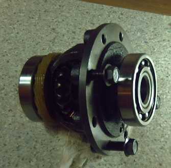
Sprint differential (drive gear removed)
The ball bearing races were now on the outside. However,
lots of car wheel ball bearings are
simply greased, not running in an oil bath. So are trailer wheels. And
the CV joints are just greased. An oil bath was only needed for the
transmission gears.
And of course it had the right spline sockets to fit the
CV
shafts. If the
bearings could
simply be held stationary, everything would work as before, except the
differential would be out in the open, and grease would replace
transmission oil. I "simply" needed to make up the right supports to
hold those bearings - very solid ones, preferably with grease nipples
in them.
Thus as I considered it, it gradually dawned on me that
using the original differential would solve the problems of attaching
and driving the CV shafts, cut down the price of the chains &
sprockets by having only one set instead of two, and avoid trying to
find a mobility scooter differential.
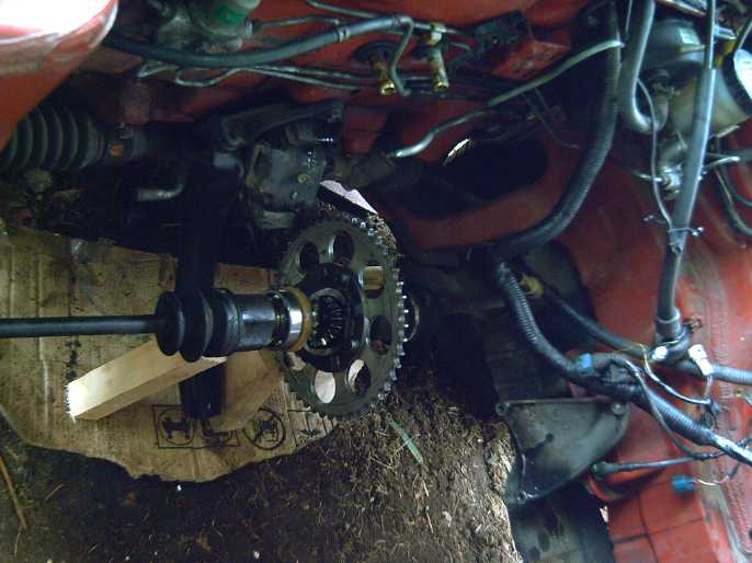
Checking the fit of the differential with the 48 tooth motorcycle
sprocket gear
I started thinking in terms of two parallel plates of
steel with holes for the differential's bearings, the midpoint (or
torque converter) shaft bearings and mountings for the motor. This
double plate would have to have welded or bolted to it whatever odd
pieces were
needed to fit it onto the original engine and transmission mounts.
If I used a different pair of plates for the second gear,
they could be mounted pivoting on a pair of bolts, and could be
adjusted exactly for whatever the chain length was, like a car
alternator slides in and out to tighten the V-belt.
The next day (16th) I went to the motorcycle recyclers and
found a 48 tooth gear that had holes in the right places to bolt onto
the differential. The holes in the differential were spaced for 112mm
diameter and several motorcycle sprockets are 110mm, but the sprockets'
holes were big
enough that they fit anyway. There were three the same and I had the
dealer with his experienced eye select the best one. (In fact I found
several others as well. Most had only 4 holes; this one had all 8.) I
had to turn the center hole bigger on the lathe, but then
it fit perfectly, spinning straight and true. I was somewhat
surprised and very pleased to get this fine result, and for a very low
cost. The info on it was good:
"1972 Honda 750 SOHC" - from that, a new sprocket gear could be ordered
if needed. Worn
gears and chains it seems are a no-no, so I might well want to get one.
I also found two 16 tooth gears. 48/16 is the same as
45/15 - 3 to 1. There was room for the 48, and 16 gave the chain one
more support. The dealer tossed one in the garbage saying it was worn
and would stretch the chain, and the other he simply gave me, but it
was a
sloppy fit on a 1" shaft. Some others wouldn't fit onto the shaft.
But he got out a Princess Auto catalog and we got the
numbers for a 1" hub and a 16 tooth gear that welds onto it. It was
cheap, and I decided to order it. (Later I found the catalog on the
web.)
And he showed me several types of chain. Some had oil
inside each sealed link. These cost more and lasted longer, but were
somewhat
stiff, so they actually took more power to drive. (They had a name...
what was it?)
He also showed me an automatic chain oiler that dripped
when the engine was running, activated by the vacuum from the engine. I
think I'll go with non-lubed chain and get the vacuum oiler (assuming I
need a vacuum pump anyway for the brake assist), or perhaps there's a
solenoid activated one. I have a litre of corn oil to start with. It
will of course get on the road, and who needs petroleum oil? (I've
already found that peanut oil works better for lubing the drill on the
CNC machine. The drill breaks through the steel sooner.)
The next Monday I was given a 12 tooth sprocket gear for
my 1"
round shaft, from AGO Environmental, who make marine winches -- after
having had Saturday breakfast with a group of people including the
owner, Jim Harrington. In 2009, Jim received an Ontario premier's award
for his High Flux Telescope instrument aboard NASA's Ulysses
spacecraft,
which studied the sun from a polar orbit. To attain this orbit, it used
a gravity assist from Jupiter in 1991, and Jim's instrument detected an
unknown blast of high energy particles, which created quite a furor in
the space science community. The Galileo later detected more
of these and determined they were ionized dust from Io volcanos,
drastically accelerated by Jupiter's magnetic field. I was unaware that
any
spacecraft had been to the Jupiter system between Voyager 2 and
Galileo. But I digress.
Jim also offered to lend me 3.6 KWH of lithium-ion
batteries to try out in the Sprint. These should be about 30 pounds
lighter than 3.6 KWH of NiMH battery sticks, and the performance about
par, but it'll be interesting to see if there's any noticable
difference. Of course the difference between 87 pounds versus 115
pounds means less than either one versus 270 or so for the equivalent
performance in lead-acid. If I used NiMH AA cells, 3.6 KWH would be the
same weight as the lithiums, but the AAs just don't seem as robust as
the D cells for high current applications, and it's harder to work with
so many tiny cells.
Sometime in all
this, I decided to
design the unit with the mechanical torque converter in. It was what
was really
needed. If the worst came to the worst and I couldn't make it work, I
could put a planetary gear in instead and at least have a moving car
without changing the main framework.
The 12 tooth gear
(instead of 16) makes a 4 to 1 ratio, limiting
the
top speed more,
but
the torque converter will need to do even less, maybe 2 or 3 to 1
torque increase,
to successfully drive the car. Then I could make any adjustments
that improved the converter, and then better
estimate the best final chain drive ratio.
Mock-up of drivetrain mountings with cardboard and wood.
This helped establish shapes and sizes for the steel parts.
To make the real thing of steel was trickier than with
cardboard. Two precise holes for the 2.83" bearings weren't trivial
things to cut without special tools or a cutting torch. (Yes, I'd love
to finish
that pulsejet steel plate cutter!) I've been overspending and really
need to cut back, or I'd have got a Waterjet company to cut the
pieces for me and simply picked them up when they were ready. Instead,
I scrounged two leftover pieces of steel in spite of them having some
gaps, and
programmed the CNC to drill 24 holes around the rims of the desired
holes. Then I used the zip cutter to cut away between the holes and
finally knocked out the center with a hammer. after that, I used a worn
down angle grinder grinding disk to grind out most of the
remaining steel, and finished it up with a file until the differential
bearing fit in. That took a day but didn't cost much, and doing it
myself let me get on with it without waiting around for a
waterjet company to get to it.
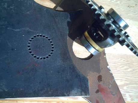
Cutting holes for differential bearings
The next day (21st) I got a piece of steel for the bottom,
and welded the main differential mounting together. Everything seemed
to fit quite well, including in the car. The upper box would be a
separate assembly, which would mount on the main box able to pivot, to
allow adjusting for somewhat varying chain lengths and sprocket gears
with about 12 to 24 teeth.
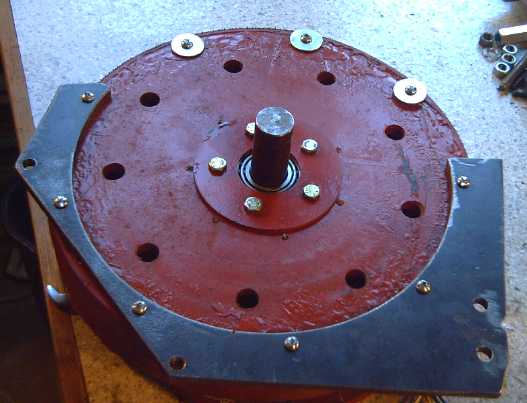
Lower drivetrain assembly
also showing parts for upper.
(Torque converter was later relocated to the inside.)
Weighing this 30 pound mass of steel (10 of which was the
differential itself), I figured the
overall weight of the drivetrain and mountings was going to be around
50 pounds. That's less than half of the original transmission, but not
trivial. It's also a heavy welded steel prototype that could doubtless
be made lighter for reproduction.
Installing one bearing holder and seal took my work
session on the 25th, and the second one the 26th. If the pieces with
their holes were pre-cut by the CNC waterjet, they wouldn't have taken
hours (and I wouldn't have got metal drill filings in the bearings). If
I decide "Sprint conversion package" is a product to sell, I'll do
that. More generically, the "FWD car conversion package" for any small
front wheel
drive vehicle would probably be very similar, all using the vehicle's
original differential. It might well be possible to make a single
"standard" unit with a few different vehicle-specific attachment bits: differential and CV shaft mounts and seals,
speedometer cable bracket, unit mounting brackets.
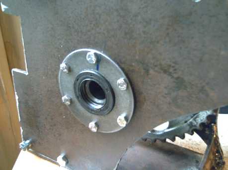
This hole with bearing seal is where the CV shaft to the right front
wheel ties in;
left is of course opposite.
I also decided the whole thing should be an enclosed unit
to keep out road dust & rocks. That just means encasing what I've
already made or am making - perhaps with ABS plastic sheet. I can glue
pieces together to make odd shaped assemblies. (Rats, I should have
known making the box
with irregularly shaped scraps of steel would come back to haunt me!)
On the 27th I cut a piece of steel to hold the motor and
fitted it to the base frame. The piece was left over from the outside
of cutting motor rotors, so it's not entirely coincidence that the
semicircle cutout should be just the right diameter to mount the motor.
The pivot is the top-rear threaded rod tying the left and right sides
at the top.
The center and front bolts have slots so the unit can pivot up and down
a bit to adjust the chain tightness.
Checking the fit of the mounted motor,
with the torque converter input rotor and thrust bearing placed on the
shaft.
I also selected a piece for the right hand side (not
shown), which
will hold the bearing on the far end of the shaft to steady the torque
converter output rotor and the small sprocket gear. Later I cut the
grooves in it so it pivots up and down to match the motor.
A Thought
This project went suddenly from a "typical" sort of
under-hood electric conversion to an "advanced" one that eliminates the
heavy, lossy transmission and replaces it with a lighter weight
drivetrain
having low losses, to match the highly efficient motors. It should get
very good mileage. (tho maintenance of the chain drive will be
higher than an oil filled transmission.)
The system should be good both for highway speeds
and to provide that extra 50% electric driving range that I've been
trying to achieve over "typical" EV implementations. For now of course
that's on a converted purely electric car rather than a plug-in hybrid
made simply by adding-on an electric motor to a rear wheel. But the
mileage will be all the better for the car being so lightweight. Fondly
(whether or not realistically) I dream of it being under 100 watt-hours
per kilometer -- actually beating that 6 MPH mobility scooter!
Nickel - Metal hydride Battery Project
"Handy Battery Sticks" are now for
sale
12 volt, 10 amp-hour, D cell
Handy Battery
Sticks (~26" long, 1900g): $105
12 volt, 10 amp-hour, D cell
Quintos Battery
Sticks (~7" long, 2200g): $120
6 volt, 10 amp-hour, D cell
Battery Sticks (~14" long, 1045g): $55
To provide a ready means of charging the 12 volt sticks,
I'm also offering adjusted Canadian Tire 2/6 amp chargers. The
adjustment, a trimpot inside, is from stopping at 14.4 volts to
stopping at 14.2 volts instead. At 14.2 volts, charging stops and the
red light turns green and says "charged". (For one stick, use the 2 amp
setting, for multiple sticks in parallel, the 6 amps.) It's not my
favorite 13.8 volts constant voltage charger, but it does work nicely
and
shuts off when it should. I use it myself. (or at least I did until I
got the solar panel.)
12 volt, 2/6 amp NiMH charger: $60
I may use three (of
these) 12 volt chargers and a 6 volt to separately charge the 42 volts
of Sprint car batteries when it's done. This is like having a battery
management system every 12 volts.
Come to think of it, you could probably charge lithiums
this way, too. Why are people doing complicated BMSs for them?
Scooter Batteries!
I've been wanting to check out NiMH's for electric bicycles and
scooters since almost the start of the project. Early in the month,
someone phoned about
batteries for electric wheelchair-scooters or a means to renew them.
I wasn't sure about renewing lead-acid AGM batteries with sodium
sulfate, but I said that I was doing nickel-metal hydride battery
sticks, and that I'd be interested to try some out on a scooter.
The AGMs were about 25 pounds each and somewhere around
30-35 amp-hours (when new). Derated to 50% discharge, that's
about 16 AH at best, when new -- not quite equivalent to two banks of
NiMH D cells.
We strapped on two 12V sticks as one bank of 24 volts, and
tried it out. It worked great! The scooter drew up to around 20 amps
starting off or climbing a hill, and only around 5 amps on level
pavement. The D cells are rated for up to 30 amps continuous and 50
intermittent, so it was well within specs for just one string of cells.
Going downhill could be 2, 0 or even -2 amps - regenerative braking.
I ended up with one
to try out that wasn't being used (it squealed - some oil helped), and
one that wasn't working to fix. The tests showed the large current
increases going uphill weren't
much balanced by the decreases going down, probably for two reasons:
First, the 5 amps on level ground shows the inefficiencies in the
system, especially the inflated rubber tires. (The manual mentions full
tire inflation as a prime factor in getting best range. ...and, 5 amps
at 24 volts is after all only 120 watts.) Subtracting the 5 continuous
amps might give typical figures of 10 A (up), 0 A (level) and -5 A
(down) - somewhat closer to a balance. Second, the motors are
geared way down. Going downhill,
the
wheels pushing the motor are instead geared way up, and friction losses
in the
gearing must be considerable. Otherwise, we might get the theoretical
10 A going down to balance the 10 A going up.
Evidently the rated speed
of the scooters is 6 MPH, and a
bank is 10 amp-hours, so at 5 amps, one might expect somewhere around
1-1/2 to 1-3/4 hours running time and around 9 or 10 miles range...
assuming paved, level ground. Not bad for 20 D cells weighing 8 pounds
instead of 50 for the PbPb's! And they can be recharged 1000 times and
should last at least several years instead of one.
A range test with two banks of batteries (20 AH, 480 WH)
gave quite a different result in actual fact. I rode it to the shopping
center (and mailed a parcel), a little farther to a friend's house, and
back. It was probably under an hour's riding time and
just under 4 Km. The voltage gradually dropped from 25 volts to 23, and
on the last long, steep hill to home it was down to 22 and 21 volts and
definitely flagging. It even dropped below 20 volts a couple of times
as I rode back into the yard.
Measuring the batteries separately very soon afterward
showed one at 11.2 volts and one at 12.2. Neither tube was warm, so the
connections were probably good. Those are both pretty low, but perhaps
one hadn't been quite as well charged initially as the other.
The hills were of course a major factor: the batteries
draw 3 or 4 times as much current going uphill, and the scooter slows
way down, so it's chugging away at high current for a
considerably longer time than for the same distance on the level. Even
slight grades increase current to 7 or 8 amps. And at 20 amps (10 per
bank), the batteries would definitely be drained in less than an hour.
The sidewalks were also very rough - now I understand seniors riding on
the street in preference.
Conclusions:
1. Theoretical range on flat prairie asphalt is no measure of actual
range in hilly areas on bumpy sidewalks.
2. The scooters use a surprising amount of power per distance. If a
friend's Suzuki Swift Electric uses 180 WH/Km in hilly areas, around
maybe 100 WH/Km for a low speed scooter can't be considered very
efficient.
3. Vehicle weight is evidently not as important as one would suspect,
comparing the above 1950 pound car with the 325 pound scooter (both
including driver).
4. Every bit of efficiency that can be squeezed out of the motor and
drivetrain - as I have been trying to do since I started the Electric
Hubcap project - is priceless.
He thought the NiMH
batteries would be more acceptable commercially if
they would fit into the same boxes as the lead-acid batteries. It's a
good point, however, five 2-cell sticks is five times as hard to make
as one 10-cell. I was trying to think of some way it might be made
easier. I think that might take a custom molded case. Then I realized
(on making a few) that doing 5 short pipes is still no harder than
soldering all
the cells was, so I'm going with it!
'Quintos' 12 volt battery stix - just 2 cells per tube to fit where
lead-acids went before.
Two boxes of three banks of 5 NiMH pipes (arranged in-line, here 30 AH
@ 12 V) can fit
into a little
wheelchair-scooter
battery box, have substantially longer range, and weigh 30 pounds
instead of 50 pounds with PbPb.
Heatshrink Tubing Battery Sticks
Someone linked me to an article with battery sticks
(apparently my first "clever" name wasn't very original after all) made
with
heatshrink tubing and some sort of metal ends. I thought that looked
great! But first, where would I get those metal ends? Then, I realized
that that heatshrink tube probably costs over 20$ for a 3 foot piece,
whereas the PVC irrigation pipe is 15$ or less for a 20 foot piece, and
that
those special metal ands probably cost a couple of bucks each.
I decided that (assuming I could even find workable metal
ends) it would really depend on the requirements. The heatshrink 'pipe'
is lighter and the battery will be thinner, but it's somewhat flexible,
and tho the labour is less, the materials are more costly. Another
concern (depending on application) is that the heatshrink and the
battery label/cover could potentially be ripped or wear through if next
to metal, exposing the case of the cell to being shorted to the frame.
The irrigation pipe takes more room (it's bigger diameter
than it needs to be, but I can't find anything closer that's light) but
it's rigid and cheap, and uses ordinary 1/4" bolts (I use stainless
steel) for the ends. It takes a few more little steps to put each pipe
together. It would take a good deal of hard rubbing for a piece of
metal to get through this pipe and short a cell case to ground.
All in all, unless space is a concern and the diameter
makes the fine difference between 'fits' and 'doesn't fit', I'll stick
with the rigid pipes.
Heatshrink tube Battery Stix
(120 cells for 144v Honda Insight Hybrid battery.)
I think this type of 'pipe' is what "flat top" dry cells
are for: they'd help keep the heatshrink from flexing at the joins.
There's a hidden expense on top of the other costs - the flat top cells
cost about a dollar more without having any better performance. In the
above image, that's an extra 120$.
One possible way to do a thinner rigid tube:
Heat a thin sheet of ABS plastic in the oven until it's limp and then
form it into a tube.
My technique needs work, tho.
NiMH Chargers for Scooters, etc.
Charging NiMH
batteries proved to be a thorny problem for commercializing NiMH sticks
for scooters.
Unlike the lucky hit with the 13.8 volts car charging systems being
ideal for NiMH car batteries, plug-in PbPb battery chargers generally
want to pump current into them until they hit 14.4/28.8 or more volts
(1.44
volts/cell) -
effectively meaning until they fail or burst, since they simply won't
go much over 1.42 volts/cell. And different machines have internal
chargers or external chargers,
each with its own idea of the best way to charge PbPb batteries
and turning a blind eye to all other battery chemistries.
It would be easy
enough with a whole new
charger... but was there a way to use the existing ones? Could
some sort of adapter do the job? The trick was to not let the voltage
to the NiMHs go over about 13.9 (or 27.8) volts, and also still have
the charger think
they were attached and charging. Then they could simply be left plugged
in all the time except when the scooter was in use. That's an easy
charger to make, but it's not the way most PbPb or NiMH chargers work.
Some NiMH chargers are ultra-fast. As I mentioned last
month, I don't believe that's a good way to get the best life out of
the
cells. Some are made to bring the charge up to full in a few hours.
Then either they shut off (okay), or they expect the user to shut it
off (not gonna happen). Still others take 25 hours or more to charge
the battery, in which case the current isn't too high to simply leave
on.
But as I said last month, I think a 1.37-1.39 volts/cell
constant voltage charge is optimum, charging fast at first,
then tapering off to a trickle by the time the cell is full. I'm pretty
sure this is the way to maximize battery life, and it's a "no cares"
system - just plug it in and forget about it. The scooter could be left
plugged in all the
time except when it was in actual use.
For chargers that put out a constant 14.4 volts, one
expects the easy
thing would be to put in a diode to drop the voltage by about .6 - .7
volts to 13.8 - 13.7. That usually needs a resistor across it (eg, 1KΩ)
to tell the charger there's a battery connected. If it's 14.1 volts
(also common), a schottky diode only drops .4 volts. But some chargers
may put out 15 or more volts to try and bring a battery up; some put
out pulsing voltage; some reduce to 13.6 or 13.3 volts once they think
the battery is charged (these are the better ones).
Is there some way to make an adapter that will handle at
least more of these situations?
The most obvious way to make an adapter would be an NPN
transistor emitter follower with a 14.4 volt reference zenor diode
setting the
base voltage for 13.8 volts at the emitter. However, that voltage is
probably just a touch too high at the base if the charger is only 14.1
or 14.4. (See Solar Voltage regulator, next heading.)
A PNP transistor feeding the battery from the collector
might be better. That needs good control of the base current, eg, with
a rail-to-rail output op-amp. I picked the LM318, which is good to 40
volts. One input is to be a zenor diode voltage
reference, the other a voltage divider from output to
ground (with a trimpot), that sets the 27.6 volts. If
the charger voltage was below about 27.7 volts, the full voltage (minus
Vsat of the transistor, about .1V) would be passed through, but if it
was
above, the output would be limited to 27.6 volts regardless. It
wouldn't handle all the clever tricks a "smart alec" PbPb charger could
throw at it, but whatever the charger did, the
voltage would be limited to 27.6 and the batteries wouldn't be damaged.
This is probably the unit to commercialize.
The first charger I tried was unfiltered; it put out
pulses of DC. When I added a filter capacitor, the voltage was 38
volts... on a 24 volt battery charger! That was more than high enough
for the simpler NPN transistor circuit, but that transistor would need
a good heatsink. It was also really too high for the PNP/LM318 circuit,
with a good chance of hitting the LM318's 40v absolute max limit and
blowing it.
It appeared adapting Pb chargers for NiMH might have to be
done on a case-by-case basis. On the other hand, if the battery sticks
were over 200$ anyway, would buyers seriously object to spending
another 50 or 75$ on an "optimum" NiMH charger? Well, maybe!
Solar Charger/Regulator and Low Dropout Regulator
After speaking of how a constant 1.38 volts/cell seemed to
be the
ideal way
to charge NiMH batteries last month, and since the solar charge
controller I bought burned out, I made a 13.8 volt linear regulator for
the solar panel to charge 12 volts NiMH batteries.
It occurred to me that I already had the regulator circuit
layed out
on a PC board... all those MC33033 and A3938 motor controllers that
weren't going to be used again had one. I found it was one thing to
have a battery voltage supplying the regulator and another to have a
varying solar collector voltage and a heavy and varying load. I ended
up adding a
diode for its .6 volt drop, a trimpot across it to select an exact
voltage, and an extra driver transistor to up the HFE of the MJE3055
(=2N3055 in TO-220 package) for better stability under varying load and
supply voltages and currents. Evidently an NPN darlington transistor
would be better, and I got one for the next try.
With a low battery and bright sun, currents up to 3-1/2
amps or so
with 18 or 19 volts from the collector really heat up the pass
transistor. You could fry ant eggs on it. I made a heatsink similar to
the ones for the motor controller from a fan of aluminum roofing
flashing strips. It seems quite effective but they're a little longer
than is useful as the outer 1/3 of the strips stay pretty much cold
even tho the transistor and the inner end is quite hot.
13.8 volt regulator (cludjed motor controller board) with fan heatsink
fins
I also designed the low dropout regulator for use with
PbPb
battery
chargers that put out about 14.1 or 14.4 volts (...or sometimes up to
16), using a PNP transistor and a rail-to-rail opamp (LM318) to drive
the base. Nothing is above the output voltage except the supply -- the
reference voltage and output sense voltage are Vout/2, so theoretically
the supply can be as little as Vsat of the transistor, about .1 volts,
above the output. Then the full 13.8 volts is attained from 13.9 volts
or greater at the input.
For 24 volt use, one simply doubles the zenor diode Vref.
For low
dropout 36, 42 or 48 volts, I need to find an opamp that won't blow up
at 38 or 40 volts.
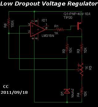
Low dropout voltage regulator for charging NiMH batteries (13.8v)
from a typical PbPb battery charger (14.1 or 14.4v)
(Please be aware this circuit is untested.)
LED Lighting Project
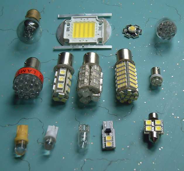
A selection of 12 volt LED lights
Front: yellow & white LED, incandescent, and brighter LED small
side lights (the 'circuit board' one fits the same sockets); interior
light
Middle: "headlamp"(?), 3 models of rear turn/brake lights (right one is
too bright!), and a small light
Rear: incandescent type, huge 4000 lumen 50 LED emitter for the shop,
6V emitter on
"regular size" hex heat sink board, another 12v light.
More Car Lighting
Last month I put LED rear turn & brake lights in my
Tercel. Those seemed great, so I ordered lights for all around the car.
Most of the packages (of those that came in a package) and the lights
themselves had no brand name or numeric marking to identify the type,
so I mostly can only give the Deal Extreme part number, which was on a
sticker on each type.
For the two-filament rear light with staggered pins, I put
in Deal Extreme # 30 05186 LEDs, which come in pairs. (not in picture.)
The running light
was about
the same brightness as the tungsten bulbs, but the lit parts stuck out
farther and were only at the end. They formed more of a lit spot on the
red reflector than the old bulbs, though those also made a spot to a
considerable extent. (Maybe they light up the whole reflector better at
night.) I decided they were keepers anyway - until I got a look when I
loaned a friend my car and noticed the brake lights really weren't
bright enough. I'll look next time and
see if there's any with some LEDs along the sides and more lumens. If
not, maybe I'll change them for the brighter turn/brake lights. This
involves a bit of rewiring - sockets that fit, having the running
lights power come through on a resistor to dim them down, yet supplying
full current for brakes, and steering diodes to prevent the one circuit
from interfering with the other.
For the small side lights at the back, I used DX #
3144684.
These packages, also pairs, were also marked "Motosports Type R LED
Light". The brightness seemed about right, but again the light was
nearer the plastic and seemed to light up a smaller spot on the
reflector. (Again, it was daytime.) But again I decided to keep them. I
also tried a yellow LED (DX 2144894), but that didn't seem very bright
through the red reflector and I replaced it with the "type R".
Still at the back, I tried out two more styles of "bulbs"
for the turn signal lights. The # 70 02360 looked a little
different but the arrangement was similar and they performed pretty
much the same as the ones tried last month. The # 21 51373 was notably
brighter. These are the ones I want to try out as headlights if I can't
find anything better or made for the job, and I decided they were
perhaps too bright for turn signal lights. But with diffusers they
would make good 12 volt
interior lights for RV, boat or solar powered home lighting, for 18
$/pair.
I put the originals from last month back in. None of them
seemed to slow the frenetic speed of the turn signal blinker much. I
set up a mirror to look at the brake lights, and discovered only the
double filament ones, tail & brake lights, were used as brake
lights on my car. The turn signal & brake lights were just turn
signals. Evidently that swap won't be saving much electricity!
I also got another LED interior light. I put it in on the
off chance it might be brighter than the one I got at Industrial Paint
& Plastics. Then I remembered the rear one inside above the
tailgate
had quit working. I repaired it and installed the LED. That did it, so
now both interior lights are LEDs.
That took care of the entire back side of the car and I
decided that was enough of that for the day. Somehow I didn't get back
to it to do any at the front.
Acrylic plastic diffusers ordered - Plastic food containers as
diffusers
The place I've been trying to get acrylic plastic
diffusers from
only seems to answer about 1 e-mail a week, and I couldn't use their
web order form because it wouldn't let me put in a Canadian province,
but I finally ordered four 6" globes and four 6" 'jars'. With plastic
diffusers I can drill a hole at the top to mount a lampshade, and a few
vent holes near it for better heat dissipation - some of the heatsinks
get rather warm, not to say hot.
The acrylic "jar" diffusers idea got me thinking, and one
day I noticed a 'frosted' plastic food container. I
put it over my latest four emitter, 12 volt LED lamp. It didn't diffuse
as well as the glass - or the plastic dome - diffusers, but it at least
protected the eyes from the bare emitters. If a lampshade was to be put
over the lamp, it was "good enough".
Later I found some translucent plastic jars at Industrial
Plastics. With the small bottle end cut off, they're about right for a
3" PVC adapter -
and again, only for use if the lamp is to have a shade.
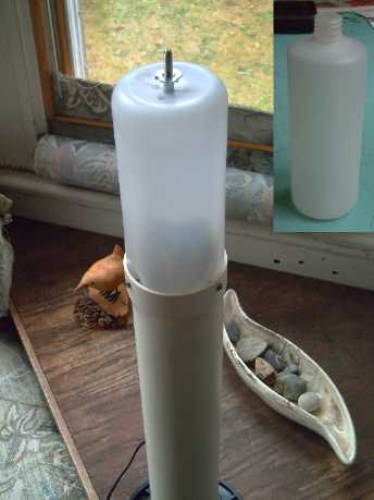
Plastic jar diffuser with lampshade holder bolt and vent holes.
The diffusion is about enough to save the eyes from immediate harm
- it's still too bright to look at, but it's a nice lamp with the shade
on it.
I had meant to use four of the new cheaper emitters for
the four
emitter lamp, but they turned out to be 6 volts instead of 3, so I
switched and used
the best ones. At 12 watts with about a 200º spread, it seems to
be at least the equivalent of a 100 watt tungsten bulb. I'll use the 6
volt ones in softer two emitter lights
instead. (I guess I could have made two parallel circuits.)
As I write this at night, the whole upstairs of the house
is lit except for the bathroom, using a whopping 30 watts or so of
power. (Though, three of the five rooms are lit rather dimly.) 12 watts
of this is a battery stick powering
the new lamp. I'll recharge that tomorrow from the solar panel, leaving
just 18 watts coming from the power grid.
Better Power Adapters
I went to a used goods store and purchased three 12 VDC
power adapters, all different but all of the new lightweight switching
regulator type. I plugged one into the four emitter lamp (now outfitted
with a plastic jar diffuser and lampshade). The meter read zero amps
with the lamp turned off, and .08 or .09 with it on: about 10 watts.
That's about 100% efficiency. The old 60 Hz transformer type would have
been wasting 3-5 watts whether the lamp was on or not. (The lamp should have been 12.5 watts,
but the voltage was 11.8 instead of 12, and LEDs are very voltage
sensitive - I could change the current resistor to match 11.8v. With a
"Handy Battery Stick" at about 12.5 volts, it was
over 15 watts and notably brighter. The other two power adapters had
the wrong plug for the lamp.)
A small drawback to this type is that many of them seem to
have a short delay before they come on, which can be disconcerting when
turning on an installed light. For a lamp, where the power adapter
stays on and the switch is on the output side, there's no delay.
17 Watt Shop Light
On the 30th, I took the 25$, "50 watt, 4000 lumens, 50
LED" emitter (DX # 66382) that I got early in the month and made an
overhead light for the shop. I made a very robust heatsink for this
"high power" unit, by my usual technique of clamping down a "fan" of
aluminum roofing flashing. In fact, the clamps were pieces of aluminum
bar too short to use for motor controllers.
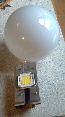
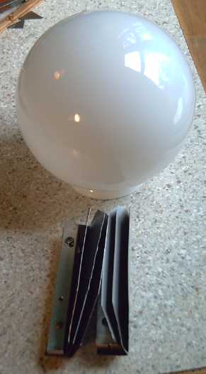
"4000 lumen" emitter on heatsink bars -- rear heatsink fins
Soon the project hit a snag: this emitter needed 30 volts.
I went and bought a couple of 32 volt power adapters (since I'll
probably
make more of these) from Boomers [used] Computers. They had a weird
plug so I went to Quealle Electronics and bought a couple of the right
ones.
I decided to use 1/2 amp of current, to give 15 watts to
the LEDs. The power adpater put out 31.8 volts, and I put in seven 27 Ω
resistors in parallel, giving 3.85 ohms (at 1-3/4 watts). The voltage
across the resistors was a little over 2 volts (after it had run a
while - it started from cold at 1.8v), yielding about 17 watts...
assuming they were still
27/3.85 ohms when warm. (I didn't again check the supply or emitter
voltages.)
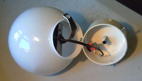
The emitter-heatsink assembly just squeezes into the globe. There are
four vent holes in the plastic top piece.
In the 'fixture', an AGC ("AGO") fuse plugs in one wire and current
setting resistors are on the other.
The bent aluminum bracket screws onto the center pipe (which has no
wires in it) to hold the inner assembly.
When I went to hang it up, things got messy. It was old
knob and tube wiring with a wierd fixture that couldn't readily be
changed, the rather large adapter had a fat computer power cord instead
of just two prongs, and it all had to hang from a plaster casting in
the ceiling. (I suspect these were popular in the 1870's - the house
has two.) Oh well -- it's the shop, not the livingroom.
It gives a lot of light. In theory at 17 watts it's only
around the brightness of a 100 watt tungsten bulb, but all the light is
aimed down, so it's more - seems like maybe a 150W bulb. The emitter
sits too low in the 6" globe and
the light comes mostly from near the bottom. (Not visible in the
saturated image, but easy to see by eye.) I wish I could find larger
globes - more room to work in and they diffuse the light better. The
bottom of this light is quite glaring if you look up. I might have to
order some somewhere.
A bit cluttery, but bright light for the machine shop using only 18
watts of electricity!
Turquoise Battery Project
I (finally) glued together the broken case from the
battery made a couple of months ago. There were still gaps and I
finally smeared in some duct seal. It still leaked, but I tried out two
other electrolytes: potassium chlorochromate, AKA chromic acid, or as
I prefer to
think of it, potassium chromate chloride, K CrO3 Cl, and
potassium perchlorate, K ClO4.
Neither one seemed to help - the battery went right on
conducting poorly. If it wasn't for the fact that the
standard dry cell uses ammonium chloride (which I've tried with similar
poor
results) and works
fairly well, I might conclude that salt electrolyte must be a really
poor way
to make a battery.
With the above
thought, I dug out the
negatrode and replaced it with a sheet of zinc from a dry cell. That's
known to work (tho zinc
degrades while recharging), so I thought it might bring something to
light. The voltage of the permangante and the nickel is about +1 and
zinc is -1 in salt solution, so the cell should be around 2 volts.
(Gosh, does that mean vanadium-zinc would be 2.5 volts?) It
charged up to about 1.9 volts in a few hours, but the
conductivity was no better and it didn't hold a charge long. (Of
course, I was trying to charge a cell with the negative side already
charged, which isn't a very good way to start.) Evidently the negative
electrode isn't the problem, because this is a sheet of solid zinc,
with a wire soldered to the back side - you can hardly get better
electrode conductivity than that - and zinc is known to work well, at
least for 10-50 charges - and many more with pocket cell construction.
Performance perked up somewhat over the next few days
mostly on 25mA charge and a few short discharge tests. The cell charged
up to 2.1 volts and more, and later tests were better than earlier
ones, the cell holding higher voltages longer... but still pathetic -
the voltages being held after 1-3 minutes (gradually lengthening) were
under a volt at only 40mA discharge rate. I've done much better cells
than this. The gradual improvement may actually be due to migration of
the zinc to form more surface area than a plain sheet, or it may just
be because the electrodes are starting to balance a little better with
cycling, having started one charged and the other not.
On the 28th after a discharge test (best to date - still
pathetic) I pulled out the zinc to put some zinc oxide powder under it,
hoping to up the conductivity with something besides a smooth zinc
sheet. I noticed a white powdery sheen on the separator sheet: the zinc
had already been depositing ZnO on it during the discharge. I added
more anyway. What I added had a bit of Sunlight dishsoap in it to help
keep it in place (as far as that's possible with zinc).
This proved bad - I had put in a slightly undersize
separator sheet, thinking a zinc plate couldn't get over the edge.
But of course the powder did, forming a low resistance path between the
electrodes. Performance suffered markedly. I took it apart again on the
night of the 29th and replaced the separator sheet, adding fresh ZnO as
well as putting the sheet of zinc back in. This seemed to make it even
worse. Of course, the powder wasn't properly compacted.
I took out the powder and rinsed the separator, and
replaced only the zinc sheet. It didn't discharge much better, but the
voltage held higher, longer, when there was no load. Perhaps the
biggest change is the dishsoap in the zinc powder -- I thought it was
inert (why did I think that?), but now I'm thinking it's the dishsoap
in the negatrode that's been causing the self discharge. There's still
some in the "+" side, apparently not causing the problem. I've probably
been using too much to start with, too. Someone using CMCs as binders
said "use less than 1%", and looking at recent mixes, I've been using
much more dishsoap than that, several percent. It's probably more than
enough to saturate the electrode.
But this not insignificant "aha!" does nothing for
conductivity. I'll run a few more cycles and it may well improve, but
unless it's dramatic it's probably time to make a new cell.
Perhaps the next thing to do is take the manganese dioxide
side of a dry cell for the positive and try with that as well as the
zinc negative. If I can't get good, working ingredients from a working
regular
dry cell
to work well, the problem must be something pretty basic. (Why didn't I
try
this long ago? I guess it's because I was preoccupied with alkaline - I
did it with nickel and cadmium instead.)
Hah! - Maybe I should try to make a [Mn/Ni]-Zn or even
plain cheap Mn-Zn rechargeable cell. I think MnZn should be rechargable
if KCl is the main electrolyte instead of NH4Cl... and, hey, this is a
[Ni/Mn]-Zn /mainly KCl cell I'm now charging with improved results each
cycle. If it has a removable lid, then if
it shorts out, you can open it, pull out the zinc electrode, and
replace the separator sheet. If it gets weak, replace the zinc. Or
sprinkle in zinc oxide (no dishsoap).
http://www.TurquoiseEnergy.com
Victoria BC