Turquoise
Energy Ltd. News #45
Victoria BC
Copyright 2011 Craig Carmichael - November 5th 2011
http://www.TurquoiseEnergy.com
= http://www.ElectricHubcap.com
= http://www.ElectricWeel.com
Feature: Battery Technology
Breakthrough!
'Grafpoxy' coated metal grills enable
new salt electrolyte battery
chemistries.
Month In Brief (Summaries -
and - gosh, editorial comment)
* Governments, Oil Companies, to ban electric cars?
* 7 Billion for Halloween & the coming Population Drop
Electric Hubcap System
* Motor contoller finally fixed, tested - works great.
* Motor over-revs at 42 volts and fails violently - analysis of
failure, weak points.
Electric Weel Motor - no report
Mechanical Torque Converter Project
* Gear Reduction in Constantinesco's car - it doubtless had gear
reduction at the rear axle to lighten the job of the mechanical torque
converter.
* A better "centifugal clutch" mechanism
* Sprint is hard to move by hand at 4:1 (chain/sprockets) reduction -
converter
still has a big job
Sprint Car Conversion Project
* Drivetrain pieces come together day by day
* Fit into car and moved car by hand by turning torque converter
drum
* Had main box rewelded, painted it all up with ersatz 'powder coating'
(see TENews #42)
NiMH Battery Project
* Simple constant voltage charger for 12 V Battery Sticks: 15.0 volt
power adapter + 2 diodes drop = 13.8 volts. Small resistor prevents
overloading power adapter.
* Got 5A chargers for 3.99 $
LED Lighting
Project
* LED Lighting: Good for your Eyes?
* BC Hydro subsidies for LED lighting?!?
* "Standard" LED Globe Light Fixtures For Sale
(No wiring necessary. See: http://www.TurquoiseEnergy.com/TEcatalog/
=> LED Lighting Products.)
* Also have a limited selection of 12 volt/car LED bulbs for local
consumption.
* Simple 12VDC Lighting "Grid Tie" part -- 12VDC power adapter for AC
side power supply.
Turquoise Battery Project
* Vanadium-Zinc cell
* Low conductivity: Aha, the culprits!
* Idea: epoxy-graphite coated copper grill current collector
& terminal (turf graphite sheets and carbon rods!)
* Zinc electrodes in salt solution may be much better than in
acid or alkali
*
A
working battery cell made! - no deterioration with cycling
seen
* Grafpoxy
grills work! Breakthrough unlocks the door to new salty
battery chemistries!
* Carbon nanotubes with methylbenzene (toluene) solvent?
* Remaining issues for practical battery cell products
Newsletters
Index/Highlights: http://www.TurquoiseEnergy.com/news/index.html
Construction Manuals and information:
-
Electric Hubcap Motor - Turquoise Motor
Controller - 36 Volt Electric
Fan-Heater
- Nanocrystalline glass to enhance Solar
Cell performance - Ersatz 'powder coating' home process for
protecting/painting metal
Products Catalog:
- Electric Hubcap Motor Kit
- Sodium Sulfate battery longevity/renewal
- NiMH Handy Battery Sticks, Dry Cells
- LED Lighting Products
Motor Building
Workshops
...all at: http://www.TurquoiseEnergy.com/
(orders: e-mail craig@saers.com)
October in Brief
 I
thought October would be much like September. For
another week I plugged away day by day at the Sprint conversion,
completing the drivetrain part by part and finally mounting the whole
unit in the car to check the fit.
I
thought October would be much like September. For
another week I plugged away day by day at the Sprint conversion,
completing the drivetrain part by part and finally mounting the whole
unit in the car to check the fit.
And I figured
out a better "centrifugal clutch" wedge system for the torque
converter. Moving the car by turning the torque converter output drum
pointed out what a big job the converter has to do if the
Sprint is going to run well, even with the 4 to 1 chain drive reduction
following it.
The car work didn't stop me
from doing the odd battery experiment... and I figured out where the
high
resistances inside my own batteries were coming from: the positive
electrodes were swelling and losing conductivity - internally too, but
even more they were becoming isolated from their graphite backing sheet
and the carbon terminal post.
Then I thought of
a "grafpoxy coated grill" system for making electrodes. Turf the
graphite sheet and the carbon rod - compact the electrode around a protected
metal grill - the ideal construction! Grafpoxy coatings could do for
rechargeable salt
electrolyte batteries in 2011 what nickel coatings did for
alkaline electrolyte batteries in 1899 - make them practical.
I meant to leave it at that and get back to the Sprint and
the torque converter, but I just
couldn't leave such a promising development on the back burner!
I made a test cell (NiMn-Zn). The negatrode was simply a sheet of zinc
from a dry cell. 5 ohm
resistance readings on the positrode from any point to the terminal
looked promising indeed, and it
did in fact work, apparently with gradual improvement and without
deterioration over a number of cycles over a week.
 Adding
toluene to
(hopefully) create carbon
nanotubes seemed to up the current capacity a bit. Here was my first
actual, usable
battery. Open circuit voltage was
around 1-3/4 volts, and it would drive over an amp (1 ohm @ >1 volt)
for about 30
seconds and put out over 1.5 volts at 150 mA for 10 minutes, or 60mA
for around 20 minutes,
holding over a volt (>40mA) for another hour and more. A proper
zinc electrode should greatly improve the running times, like maybe
20-30x.
Adding
toluene to
(hopefully) create carbon
nanotubes seemed to up the current capacity a bit. Here was my first
actual, usable
battery. Open circuit voltage was
around 1-3/4 volts, and it would drive over an amp (1 ohm @ >1 volt)
for about 30
seconds and put out over 1.5 volts at 150 mA for 10 minutes, or 60mA
for around 20 minutes,
holding over a volt (>40mA) for another hour and more. A proper
zinc electrode should greatly improve the running times, like maybe
20-30x.
I also discovered there's a zinc peroxide (ZnO2) which
might - possibly - make a good positrode. It's the first indication
I've seen that such a thing might be possible. A ZnZn salt battery
would certainly be very economical, and it should achieve over 100
WH/Kg energy density if the voltage is reasonable.
 I also made a
few more LED lights, and I found out that
BC Hydro is giving rebates to customers who buy approved LED lighting
products. So I tried to get info in order that my LED light fixtures -
which are much brighter than the 'LED lightbulbs' available in the
stores - might become more affordable.
I also made a
few more LED lights, and I found out that
BC Hydro is giving rebates to customers who buy approved LED lighting
products. So I tried to get info in order that my LED light fixtures -
which are much brighter than the 'LED lightbulbs' available in the
stores - might become more affordable.
The thought of possible sales - income! - brought LED
lights to the forefront of effort. I bought more parts and
focussed on defining "production models" such as a 6" globe (image),
updated the Turquoise Energy
Products Catalog to include them (and Handy Battery Sticks), and I
attended a couple of small events trying to promote them. If ASHRAE
engineers specify them for new commercial construction or renos,
savings in HVAC equipment might actually pay for the LED light fixtures
right in the capital cost.
The day of the 17th and some time on the 18th was devoted
to looking through LEDs at
DealExtreme.com and putting together a big order - almost 400 $ worth.
I hope I
can sell a few LED light fixtures or lamps to recoup
some of that, as money is already getting low and tax credits are at
least six months away. In the process, I finished converting the Tercel
to LED lights, except the headlights (haven't found any yet), and
better determined which are the best ones to use. In the order are some
more to do the Sprint.
 Later on the
18th I finally tested the motor controller.
It
worked great, but the motor over-revved at 42 volts and came apart
violently. I neglected to consider that the higher top RPM from the
higher voltage would be well above the design intent - maybe 3000 RPM
instead of 2000, 9/4ths the centrifugal force. For a couple of days I
had been mulling over the possibility
of doing the electric outboard before my trailer insurance expired on
the 26th. (I only used it once for the Electric Hubcap Outboard trials
last November 6th. 50$ for one trip is very high priced insurance!) It
didn't seem like a big job to get it running (tho these things tend to
take much more effort and time than expected), but the busted motor
broke the camel's back.
Later on the
18th I finally tested the motor controller.
It
worked great, but the motor over-revved at 42 volts and came apart
violently. I neglected to consider that the higher top RPM from the
higher voltage would be well above the design intent - maybe 3000 RPM
instead of 2000, 9/4ths the centrifugal force. For a couple of days I
had been mulling over the possibility
of doing the electric outboard before my trailer insurance expired on
the 26th. (I only used it once for the Electric Hubcap Outboard trials
last November 6th. 50$ for one trip is very high priced insurance!) It
didn't seem like a big job to get it running (tho these things tend to
take much more effort and time than expected), but the busted motor
broke the camel's back.
Too bad - I might
have actually sold a motor kit or two with an actual application for it
that was demonstrated to work. Who knows for sure how long the Sprint
conversion may drag on for with the untested torque converter plan and
all the other things I'm doing? On the other hand, I now realize the
rotor compartment needs a little more beefing up before the motors hit
the market, and I'll be trying to improve the magnet gluing system a
bit.
AFAIK the controller was still working. On November 1st I
finally ordered some IR2133 V2 motor controller boards, designed in mid
August. On a list someone mentioned iteadstudio.com, and I ordered 10
boards there for half the price of two from APC - wow! High priced
parts are what makes my stuff cost a lot, and this is a good find.
One more motor detail that's been wanting is a better
formulation of ilmenite for the coil coatings, one that won't flake
off. I didn't have time to try out the zinc oxide additive. Until the
coil coatings are improved the Weel motor isn't going to get done.
Governments, Oil Companies, to Ban Electric Cars?
I've just heard a rumour that our (Canadian) government is
planning
to ban conversions of gas cars to electric. This sounds crazy, but it
follows a secret
provincial ban on
registering converted cars last year in Ontario, evidently since
repealed. Since it's virtually impossible to buy an electric car from a
car maker, that would virtually mean a ban on electric cars. If true
such a
move,
clearly at odds with the public interest and the whole planet's, can
have only one real purpose: to prevent the public from making the
switch from gasoline to electricity even with their own hands. This
slow switch
which has
been happening on a small but growing scale with improving electric and
electronic technology, and in the clear absence of any
intent by car makers to produce practical electric cars -- besides a
handful of overpriced units to bandy around and say "See, we're making
them!" They sell one at inflated price
where ten thousand are needed.
Car companies can make a gas car to sell for around
10,000$. Canadian Electric Vehicles (just one example) can convert your
gas car to
electric for around 10,000$ Doing it yourself is cheaper. That's
20,000$ for a brand new electric
car, partly made by hand with Canadian labour in small shops, and with
a
discarded gas engine system left over. From scratch, an electric car is
obviously simpler and easier to build than a gas car. Maybe a basic one
should cost 6000-8000$. Yet a Chevy Volt,
essentially
publicly funded by the billion dollar bailout to GM, costs over 40,000$
-- if they would actually sell you one. They claim
they can't do it for less. Tesla motors, the one seeming bright spot
since Zenn ceased production, is going public, but they're also ceasing
production of their 100,000$ roadster. They plan to make a 50,000$
electric car next year, but there'll be a gap in production. As a
privately owned and funded company it was hard to sabotage, but if
patterns repeat, now that the miscreants are free to buy up the shares
the new model will never be built, and Tesla will cease to supply
electric cars, tho it's so well known now it may be kept "open" to
prevent public outrage at its closure.
Another disturbing rumour I heard this month (from what
seems like a good source) is that the oil companies have bought up
virtually all the battery making companies in China, and forced them
all to sign agreements that their battery sales need to be approved by
them. Obviously, a ban on sales of batteries for electric transport is
the objective.
Oil reserves, CO2 emissions and global
warming would be dead issues were it not for the few actively,
deliberately and cleverly blocking
change. In fact, they might never have been issues. How can the 1%
responsible for this or complicit in it look their neighbors in the
face?
And it would just one more little item in the gradual but
ongoing curtailment of freedoms of we who were a much freer society
within the memory of many. The gangsters that
control the world's economy are now pressing us to the wall.
Winston S. Churchill's "broad, sunlit uplands" for humanity that
followed World
War Two are being rapidly fenced off with "Private Property Keep
Out" signs around them.
The 99%
are beginning to realize that the psychopathic greed and avarice of the
1%
is destroying civilization, and are now
demonstrating in numbers in cities all over. "They continue to block
alternative forms of energy to keep us dependent on oil." is just one
of a long, sickening list of indictments in the Occupy Wall Street Statement
of Solidarity. If nominally democratic
"bought" governments don't
start
doing the things people want and need done, when enough people have had
enough, there may be a revolution. But what then? Military
dictatorships might restore order, and maybe even summarily get rid of
the
gangsters who are lording it over us now. But it would likely be no
freer. Is that what we want?
It's easy to feel the situation is hopeless. But rumours
from a confluence of individually suspect sources going back over 25
years say "Be not dismayed!" - that the troubled times we're entering
are the beginnings of a grand correction, of gradually pulling this
planet back into the main evolutionary sequence. "Communism" showed its bankruptcy 20 years
ago and has largely vanished. Now psychopathic "corporatism" is likely
about do the same. Angels and
other spirits await freewill human decisions, and when we try to do
better, to learn, to educate, to contribute to real human health or
planetary welfare, the results may be better and more far-reaching than
we expect. All things work together for progress.
Seemingly small electoral system changes would lay
foundations for a proper democratic
system. I suggested some of them in my
2003 booklet Fundamental
Principles of Democratic Government . They should result in
real
leaders becoming electable, transfer the real decision making power
from
political partisan ("party") factions to the individuals in the
legislatures where it
belongs, and enfranchise citizens to instigate changes and actions
instead of just
to ineffectively protest someone else's imposed decisions and programs.
The Choice Ranking vote, titled "BC-STV", was chosen as the best voting
system by most of the BC Citizens' Committee on Electoral
Reform in the same year, and Australia already uses it. In Canada (and
Australia), it needs to be enacted along with
direct popular election of the prime minister and provincial premiers.
With the fair voting system where one puts who they really like
best first regardless of preceptions of their electability, and without
the schizophrenic election of two offices with one vote (MP and PM),
the real
ability of the public to elect numerous popular non-party figures who
haven't
worked their way up through a corrupt political hierarchy, would make
the whole system much less open to corruption.
Simply creating the Department of Progress
(mentioned in various issues of TE
News from #21 on) would
provide
an ability to
foster both development and adoption of valuable technologies
and new systems and institutions of governance, where they're needed,
and rein in vested economic interests that attempt
to entrench old and inferior technologies and systems with unfair
tactics against the public interest. Such a department might itself
carefully study and make recommendations for vital political structural
reforms, for discussion and probable enactment by parliament.
And as
another example of things such a department might accomplish, surely it
could come up with a well
conceived national pension system, perhaps formed as a trust, that
would unlock career changes for
the many experienced citizens trapped a decade or more too long in one
job by pension
considerations, and set companies free to hire workers of any age.
To attain to such improved systems we must recognize that
we are one human family on one planet in a stupendous cosmos, spiritual
sons and
daughters of an infinite First Source and Center who encompasses all,
and start to act accordingly. Perhaps John F. Kennedy had the
essence when he said, "We all
drink the same water; we all breathe the same air." We can't
bring peace on Earth and goodwill among men unless our solutions are
fair to everyone, everywhere.
If those who are creating the problems turn and face
themselves, as they must do on the next world if not on this one, they
must recognize inwardly that they're one of a handful of rotten apples
spoiling the whole barrel. They would
do not only humanity but their own souls and psyches a great service by
defecting from this evil - by opening their hearts to the people
they're
oppressing and helping to get long needed changes and advances
implemented.
They might well find themselves living in a better world, and discover
a
couple of things more precious than immense wealth and power - peace of
mind and
a true sense of self worth.
7 Billion for Halloween and
the Coming Population Drop
Officially our family hit 7,000,000,000
earthlings on October 31st 2011, "Halloween" in North America. Most of
my life
I've heard about the "population explosion", the "exponential
growth" of Earth's population and how it just can't take much more. It
had everybody scared like "global warming" does today. In fact, I
think we were supposed to be over 12 billion by now and all starving.
But birthrates in most of the world (with a few notable
exceptions) now are such as to utterly falsify this picture. A couple
of years
ago I saw it predicted that the population would peak in 2055 and then
start
to decline. That was a big surprise to me. Now I'm even seeing 2035
instead.
Halloween evening the 7 billion produced only two costumed kids to come
to the
door for candy, where 30 years ago, there were usually around 40. This
doubtless indicates changing customs and I was late putting the porch
light on, but there certainly are fewer
children around.
We now have an aging population, full of people like me
who lived much of their younger life with the real possibility of
nuclear holocaust, and who bought into "the population explosion" and
thought it might be a service to humanity not to have kids. When we die
off, there are few in the next younger age groups to replace us.
I remember working for the Victoria school district in
the late 1980s when numbers of portable classrooms were being placed on
school grounds. Everyone was asking "Why don't you build additions and
bigger schools instead of this makeshift fix?" But the far-seeing
facilities
manager said "Look at the birth statistics. In five years these
portables will be being hauled away, and if the trend continues, whole
schools will be closing." Thoroughly indoctrinated as I was to the
"population explosion", that didn't make sense to me at the time -
How could more and more people have less kids? But
these things have happened. One high school that had 2200 students at
its peak now has 800. Today, economic times are such that many in their
20s and even 30s are still living with their parents. By the time they
are affluent enough to have a family - if they ever are - they'll be
too old.
While everyone was crying "Blizzard! blizzard!" the
population explosion "snow" simply melted into the ground. It seems
almost
inevitable
there will be substantially fewer people alive in a century than there
are
today, without
any mass starvations, pandemic epidemics, or global catastrophe having
intervened.
But will they be affluent people free to live the lives
they choose in a sustainable, boldly advancing civilization, or will
99% be regimented, poverty stricken serfs of 1%, living in a sick,
polluted
world
and overburdened with
1,000,001 petty regulations against every deviation from arbitrary
social, political and economic "norms" of the day to keep them in line?
A Battery Technology
Breakthrough
Background
There was something that wasn't explained in any battery
reference book: why are standard dry cell positive terminals a carbon
rod, when every other type of battery uses metal?
It took me a couple of years of battery R & D to
figure it out for myself the hard way: every metal I used within the
positive electrode in a salty electrolyte battery oxidized away,
including nickel, which protects the other metals in alkaline cells.
The cells were soon left with a terminal post connected to nothing
because the wire had disintegrated.
The actual electrochemistry is of only secondary
importance beside having cells that don't fall apart.
Why was this nowhere explained? I suffered two years of
failures because of this missing bit of info. Maybe it was so much
assumed to be "common knowledge" by those writing the books that it
didn't occur to them to mention it? Maybe the secret died with salty
battery research in the 1880s? Whatever the reason, I explained it on
Wikipedia in the "carbon-zinc battery" article so others might avoid
this pitfall.
Evolution
Once I understood it, I started using sheets of "expanded
graphite", and carbon terminals salvaged from dry cells. Others have
used graphite impregnated plastic sheets. But there were problems with
this approach. Butting an electrode up against a carbonized sheet
doesn't connect them together very well. My failures now took a
different form: of initially poor conductivity within the battery, that
-
worse - deteriorated further over a few days.
Browsing at (IIRC) GraphiteStore.com for ideas, I noted
that they had "electrically conductive epoxies" with various metal
powders in them, eg, silver, copper or nickel. That obviously wasn't
going to solve the problem: if the metal particles connected with each
other and to the outside, as they must to conduct, they would all
corrode away just like solid metals did.
But if one could do that with epoxy and seemingly with
'any old metal powder', what about with graphite powder, which wouldn't
corrode? I tried it out (TE News #40) and got good results.
Encouraged, I "glued" the offending parts together with
the 'grafpoxy', as I called it, and made a battery. However, the
initially
fair conductivity gradually deteriorated, about like in previous cells.
At this point, I pretty much set the battery research
aside for
a while and worked on other projects.
Invention
In October I disassembled a couple of cells and measured
the conductance of electrodes to the terminal posts. They were good
when
I'd made the cells, but now the resistances were very high - unusable.
This was when I finally realized where the performance had gone.
 But having given the issue a rest for a while, a fresh
thought crept in. Alkaline cell metals are coated with nickel to
prevent corrosion. Why not go back to using metal parts, but coat them
with
impervious grafpoxy to protect them? Then salty batteries could be
constructed much the same way as alkalines, but with grafpoxy coatings
instead of
nickel. The problem graphite sheets and carbon terminal posts could be
discarded entirely.
I made up several copper
grills with copper wire terminal
leeds or brass bolts soldered to them... why not solder and brass?
After all, it's protected. Then I realized the 90º posts would be
hard to work with. Doing them that way was perhaps a hangover from
carbon rod thinking. I did some more - and re-did some of the first
ones - with the leeds in the same plane as the mesh so they'd fit into
the electrode compactor.
But having given the issue a rest for a while, a fresh
thought crept in. Alkaline cell metals are coated with nickel to
prevent corrosion. Why not go back to using metal parts, but coat them
with
impervious grafpoxy to protect them? Then salty batteries could be
constructed much the same way as alkalines, but with grafpoxy coatings
instead of
nickel. The problem graphite sheets and carbon terminal posts could be
discarded entirely.
I made up several copper
grills with copper wire terminal
leeds or brass bolts soldered to them... why not solder and brass?
After all, it's protected. Then I realized the 90º posts would be
hard to work with. Doing them that way was perhaps a hangover from
carbon rod thinking. I did some more - and re-did some of the first
ones - with the leeds in the same plane as the mesh so they'd fit into
the electrode compactor.
Then of course, I made an electrode (NiMn) briquette
around one grill. The resistance from anywhere to the terminal was only
a few ohms, eg 5 - even better than I'd hoped. I put it in a battery
case and used a piece of zinc from a dry cell for the other side.
First grafpoxied electrode cell, and my first really
working battery.
It worked! It
was a real battery, and roughly equivalent
to a standard dry cell in current performance per electrode area.
Better yet, it continued
to work through several charge and discharge cycles with actual (though
minor) improvement with each cycle.
Further Development
That was the initial success and, it would seem, proof of
concept. But the mixture and application procedure needed improvement.
A
sheet of zinc was a crappy rechargeable electrode. An ill-fated second
battery hardly lasted a day before the positrode structure crumbled and
the leed wire came loose. Evidently there was a gap in the coating by
the
wire (tiny gaps were visible on some of the grills) - or compacting
the electrode scraped some epoxy loose and left a gap.
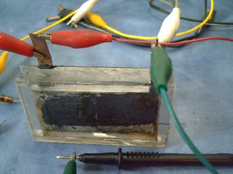
Cell #2. I put it edge up fearing it might leak at the terminals.
I think I'll make them all this way up, and liquid filled.
For best adhesion and coverage it may prove necessary to
thoroughly clean the metal with several complementary treatments,
similarly
to if it was to be electroplated.
If good results aren't forthcoming with that, I'll try two
coats, hoping the second one will bring stiffer protection and fill any
small gaps. If all other techniques should fail, I'll make molded
grafpoxy grills with no metal in them at all except a terminal post
cast inside a thick housing and - again only if necessary - pretty much
outside the cell. But I'm pretty sure the epoxy is impervious and by
good technique the grill can be made tough enough that extremes won't
be necessary. The metal grill provides better current capacity, in a
much thinner grill that leaves mainly active electrode substance for
high energy density.
 For a third try, I used copper foil and riveted it to the
grill, since the solder seemed to be a weak spot.
For a third try, I used copper foil and riveted it to the
grill, since the solder seemed to be a weak spot.
Copper grills with riveted terminals
 I put up to
four applications
I put up to
four applications
of
grafpoxy on to try and
eliminate tiny bare spots.
The structural parts for battery #3
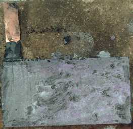
A thick positrode, compacted around one of the grills.
The painted calcium hydroxide coating picked up some purple from the
potassium permanganate.
Finished cell. The top was just set in place, not sealed.
This cell also had some
problems, but the positrode appeared to remain solid over a week or so.
Then the cell was disassembled.
The essence is there - it
can be done. The door is opened
to batteries of various new chemistries in salty electrolyte that were
previously inaccessible owing to there being no really good and
practical way to
construct a salty electrolyte rechargeable battery. Some of these
chemistries
are exciting in that they hold promise for probably higher energy
density than lithium ion and long or indefinite cycle life, and all for
the price of cheap dry cells, or of lead-acid -- without its hazards
and environmental problems.
If and when economical electric cars and trucks have a
day's highway
driving range, gas vehicles will lose their monopoly. And when weeks of
electricity from solar collectors or windplants can be saved up
on-site in batteries, perhaps too the electric grid will no longer be
such an
indispensable part of modern living for everyone.
Electric Hubcap Motor System
Motor Controller
After making the fuses bar clamp at the end of September, I wasn't
happy with it and made another the next day, that supports the bar with
a couple of plexiglass pieces when the fuses are being inserted, and
holds the
copper bars apart (thin strip
glued on beside bar after photo)
so the fuses can't accidentally be bypassed. Still
lots of room for improvement - next unit!
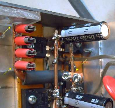
Fuses Bar: Clamp (arrow, right); Support (arrows, left)
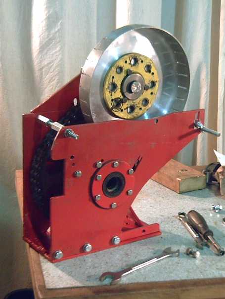
Busted Motor. One magnet punched a hole through the particle board
table it was clamped to.
I hadn't considered that going from 36 volts to 42 would
up the maximum RPM the motor would attain, and I wasn't measuring it.
The motors had already been going up to 2200-2400 RPM instead of the
intended 2000, and 42 volts might take it as high as 2600-3000 RPM,
with double the centrifugal force I had intended it to withstand.
I'm thankful I wasn't in the line of fire. Thinking of the
guy doing the flywheels to store energy in the late 1960's, whose ideas
for powering even buses from flywheels were
featured in several Popular Science and Popular Mechanics magazines
until he was killed by a big flywheel that flew apart spinning 50000
RPM in his lab, of jet engine failures, and of my own previous magnet
glue
failures, I've gotten into the
habit wherever feasible of mounting motors vertically and being face on
to it rather than edge on. (The researcher's death was the end of the
idea of using flywheels to store energy until very recently - over 40
years later.) One magnet made
a 1" x 2" rectangular hole (and the exit was much larger) right through
the table the motor was clamped to. (It was a cheap particle board end
table... but still!...)
I collected the five loose magnets from around the room. Three of them
were badly chipped on one end, but I didn't see any holes or gouges in
the walls
or ceiling. They're probably what bent all the bolts inside, ripping
them out of the PP-epoxy center plate.
Analysis of the failure
The first thing that was virtually a given was that a
magnet must have come loose from the rotor. This would have become an
obstruction in the rotor compartment, hitting other spinning magnets.
It appeared that the five magnets that came off had separated from the
epoxy, rather than the epoxy from the powder coating paint, or the
paint from the undercoat or from the metal.
They also separated from their polypropylene strapping, or
(with two of them) the strapping separated from its epoxy on the rotor
and stayed with the magnet. The strapping was mostly but not entirely
intact, unripped. Examination of the rotor disclosed areas where not
much strapping area was well embedded in the epoxy, especially near the
inner ends -- with one such weak spot on each side of the same magnet.
This
could cause the magnet under stress to pull strongly away from the
rotor on the inside. Once it broke free of the rotor behind, it would
have swung out, ripping the rest of the strapping from the epoxy, and
become a projectile.
Better workmanship
might have prevented the failure... or just delayed it until reaching a
bit higher RPM. Improving the strapping configuration
might be helpful if I can think of a simple way to do it. It's easier
in theory than when you've got a bunch of gooey epoxied strapping that
doesn't want to stay put. If I'd tried inserting a screwdriver under
the strapping at various points, it might have disclosed the weak
spots.
But screwdrivers and supermagnets don't mix very well either. Maybe
something plastic.
The rotor
compartment's outer cover, made of four winds of PP strapping, was
ripped in one place. It looked like a magnet probably flew out from
there. The point was near the top of the motor, so it wasn't the magnet
that made the hole in the table underneath. It may have been the two
magnets I
found across the room stuck together. The strength of the PP strapping
is impressive, but not unlimited. A thicker outer wall appears to be
required. But then the outer wall will be so close to the rotor it may
hinder ventilation. I also note that the outer strapping wind was
delaminated from the others. Making the outer shell by casting it
should also be stronger.
The bolts holding the rotor compartment to the stator side
of the motor were all bent, having been hit by the loose magnets. (This
is probably where the magnets got chipped.) These bolts pass through
the rotor compartment just inside the outer cover. If the
cover shell were thickened so that the bolts passed through holes
within it,
the damage to the bolts would probably have been avoided and the case
might not have failed. To enclose the bolts is a second reason to
thicken the outer wall, and to cast it. But there's not
much room between the bolts and the rotor since I minimized the
diameter of the motor. I'd really rather not redo all the molds and
everything unless there was no other way!
The center ring/plate between the rotor and stator
compartments protected the coils and stator side from damage, except
pieces of
the ring itself ripped/broke apart at the bolt holes, allowing the
motor to come apart. This was the first ring made with the new mold
casting technique, and I knew it had some dry spots without epoxy.
These weakened it.
Furthermore, I hadn't expected any real trouble, and only
six of the nine bolts were installed. All nine might just have made the
difference. But it may be that the magnets ripped the bolts out one by
one, and there would simply have been nine rips instead of six.
Corrective Actions:
1. Make a careful inspection of
every rotor after magnet & strapping installation. Try to insert
something flat under the epoxied strapping and otherwise hunt for weak
points. And maybe paint on an extra layer of epoxy after it's otherwise
finished.
2. Try to figure out a better configuration for the strapping that's
inherently stronger. I think casting it should stiffen it.
3. Recess the magnets in a bit from the edge of the rotor - maybe .1".
4. It might pay to rough up the bottoms of the magnets a bit with
sandpaper or scotchbrite before applying the epoxy. On the underside,
the magnets separated smoothly from the epoxy.
5. Thicken the outside wall of the rotor compartment, and drill holes
through it for the bolts. Or maybe just the area in line with the
magnets? (better for ventilation?) On second thought, I think I'll mold
the outer wall.
6. Always install all nine bolts to hold the rotor compartment together
and to the stator compartment.
7. Snip the tines short on the T nuts so they don't cut into the
plastic center plate so much. Or bend them over. (In some places, the
center plate ripped at the tines.)
8. Use the new shaped center plates with thicker outside edges to hold
the nuts/bolts. Ensure no dry areas after molding.
9. Make a motor controller with a microcontroller that monitors (among
other things) motor RPM and reduces power if it hits max.
10. Going back to 36 volts instead of 42
would pretty much eliminate the potential of serious over-revving. That
would make battery charging details easier too -- three 12 volt
chargers,
three 12 volt solar collectors on the car roof (800$ option), and no
single 6 volt units that have to match the 12s in current.
Mechanical Torque Converter Project
Someone gave me a washing machine clutch mechanism to
examine. With my last designs, the motor would have to get up enough
torque to overcome the springs holding the wedges in the slots before
it could start moving. I was only hoping that the maximum pressure for
starting the motor was also at least sufficient pressure to develop
good force to the output. But this is backwards. Ideally the stopped
motor should be free, unloaded, and force developed should be
proportional to motor speed.
I've decided to modify the design, and use centrifugal
force to push the wedges into the slots. This implies that the wedge
arms must be given a certain amount of mass to push them out with some
'optimum' amount of force as the motor spins. Instead of having the
springs push the wedges into the slots, they'll hold them away from the
slots, retracted, until the motor gets up some speed, somewhere in the
upper 100's of RPM.
Thus the unit will act as a centrifugal clutch that will
cut in when the motor is going fast enough to develop some force - the
sort of force that might start to move a car on level pavement. The
mass of the arms and the strength of the springs can be varied to see
what works best. It'll be unlike a centrifugal clutch in that it will
neither solidly 'engage' nor 'slip', but the greased wedge will freely
slide across the flat areas, bumping against the edge of each slot as
it comes to it.
The force of each hit will largely be proportional
to the
square of the motor speed. The frequency of the hits will
depend on the relative speed between the motor and the output rotor,
which depends on the amount of torque required. The torque will
I think be the motor torque times the total distance between slots,
over the distance for which the drum is driven at each slot - around 18
to 1.
Since I haven't made the wedges/arms/springs part of the
mechanism yet, design changes - so far - don't require any reworking of
things
already done.
Looking at the washing machine clutch, I note that the
arms could be on the outside of the output drum. In this case they
would pivot in the middle, with the weight on one side and the wedge,
facing inwards, on the other. However, I'm not sure if this would have
any particular advantage, and there isn't room to fit it without
redoing important parts of the frame, since I hadn't planned on
anything larger.
Seems to me that if the diameter is to go up, it should
probably be
the output drum that's made larger and the arms and wedges should be
kept inside it. It also occurs to me that the drum and slots could be
made wider - if not an inch, then two or three or four inches - to
distribute the force of the hits and so prevent damage from relatively
powerful forces.
Constantinesco's car & converter: gear advantage
Although Constantinesco eliminated the entire transmission
of his cars with the torque converter (which was built into a two
cylinder engine in his production model), there was a gear at the back
axle for forward-neutral-reverse. It belatedly occurs to me that this
gear probably was also a reducing gear. Given the higher RPMs of a two
cylinder gas engine and the fact that 40 MPH was probably a good top
speed in the 1920s, it wouldn't surprise me if it was as much as around
10 to 1 reduction. This means that his torque converter had a much
easier job to do than I what was thinking. That might explain why his
oscillating masses converter was successful but no one since has
managed to duplicate his success.
Doubtless the chain drive I've put in the Sprint, or
a planetary gear reduction following the torque converter before a
vehicle wheel, reduces the converter's job.
Test Setup?
I thought of making a test setup using the sprint car
drivetrain C-clamped to the workbench. Instead of hooking the input
rotor to the motor, I could hook it to a hand crank. I could mount a
fish
scale at a 6" radius from the output drum and measure the output
torque. I'd have to estimate input RPM and torque. I had another cut
down trailer axle for bearings for the same 1" shaft as the motor,
so the input rotor could be moved from the crank to the motor without
modifications (except maybe stronger springs so it'll engage at a
higher RPM).
A few days later it occurred to me that all I had to do
was put a longer axle on a motor, so that it stuck out the back end.
The handle could then go right on the motor shaft and nothing extra
except the handle need be constructed.
I hope in this way to get more of a feel for how it's
working and what gives it more or less effect and how much effect. On
the other hand, I can't duplicate motor RPMs by hand.
What's needed now is time to get to the job!
Sprint Car Conversion Project
Fittings
On the 2nd, I fitted a plastic plate on the hole in the
floor where the gearshift lever was, a plastic plate on the console,
the console back into position (with a couple of new brackets to mount
it), and the
key "Park" release cable and the forward-neutral-reverse switch into
the plate. Around the switch I put an aluminum shroud to make it simple
to shift to where you mean to shift and prevent accidental shifting.
I've had this shroud safety idea in mind for well over two years, and
now it's finally taken form, albeit with some rough edges. I'm leaving
the cable in as another safety feature: to switch into or outof "Park"
(which now only allows the key to be removed and locks the steering),
you have to pull the cable. Takes two hands. I'll probably fancy it up
with a lever to pull the cable at some point.
A means for having to press on the brake to go from
neutral into "Drive" (forward or reverse) would be tricky, but I don't
think it's necessary since the car won't start to move until you press
on the electron pedal.
Of course, the parking brake becomes vital, since there's
no other way to lock the wheels.
On the 3rd, I fitted the speedometer gear to mesh with its
gear on the differential, using a short bit of angle iron as a mount. I
don't want to do an electric car and not know how fast it's going or
how far it's gone! I wonder if it should have an oil drip too, seeing
the gear teeth and the bushing are no longer running in an oil bath. It
does turn slowly - perhaps grease would do.
On the 4th I fit an axle mounting for the small sprocket
and the torque converter drum -- a cut-down trailer wheel bearing hub
from an early motor. This required making another large hole in the
mounting plate, which I tackled with the same technique as the
differential bearing holes. On seeing how it all fit, I saw I'd have to
cut new slots for adjusting that side, do a new axle to fit... and move
the speedometer gear.
The next day I found a slightly better bearing hub and fit
it, and cleaned up some details, including cutting an axle rod,
extending the slots and moving the speedometer gear. All this stuff
takes a lot of time when things aren't ready made for you. It's one
thing after another, one little job at a time (inevitably taking much
longer than anticipated), all adding up.
On the 6th I got chain and fitted it in. It turned out
that the bulk chain was the long-lasting sealed chain. Cranking the
unit around by hand showed that all those little rubber seals on the
links really do give it a lot of resistance to turning. I suspect it'll
reduce efficiency enough to show up clearly in reduced performance and
mileage. I'll definitely try out some other chain as well once things
are working, to compare and see if that's the case.
I took the unit in to see how long the chain needed to be,
and the merchant at Victoria Motorcycles offered to redo my amateur
welding free. His good TIG welder could do a much better job, just to
help out. True, I would
hate to have the welding fail on the road, but I didn't think it would,
and this being the main unit
that everything else fitted onto, I couldn't give it to him without
stopping work myself.
 In the next couple of days I made some brackets and bits and
fit the unit onto the original engine and transmission mounts, and I
cut a keyway into the shaft. I'd been told I could do this properly
with an end mill using the drill in my CNC machine. But someone else
said the mills should only be used in a collet chuck, not a drill
chuck, and anyway Western Equipment was out of 1/4" end mills. Instead
I
bought a '1/4" lathe tool', which was the square shaft key I
wanted... but made of tool steel with sharp beveled edges on the ends.
I roughed out the keyway slot with the angle grinder, then used a
hammer and the 'lathe tool' to finish gouging out the inside corners of
the slot. This, plus the close fit in the sprocket gear and in the
torque converter drum hub, gave the desirable close machined fit,
albeit with some rounded outer corners on the shaft. On the 9th, I
tried out the assembly in the car. It was a bit too far to port - the
inner CV boot end fitting slipped off its place on the starbord CV
shaft when I put it in. Later I moved one bolt hole that positioned the
rear
end 1/2" over and the shafts seemed to fit okay.
In the next couple of days I made some brackets and bits and
fit the unit onto the original engine and transmission mounts, and I
cut a keyway into the shaft. I'd been told I could do this properly
with an end mill using the drill in my CNC machine. But someone else
said the mills should only be used in a collet chuck, not a drill
chuck, and anyway Western Equipment was out of 1/4" end mills. Instead
I
bought a '1/4" lathe tool', which was the square shaft key I
wanted... but made of tool steel with sharp beveled edges on the ends.
I roughed out the keyway slot with the angle grinder, then used a
hammer and the 'lathe tool' to finish gouging out the inside corners of
the slot. This, plus the close fit in the sprocket gear and in the
torque converter drum hub, gave the desirable close machined fit,
albeit with some rounded outer corners on the shaft. On the 9th, I
tried out the assembly in the car. It was a bit too far to port - the
inner CV boot end fitting slipped off its place on the starbord CV
shaft when I put it in. Later I moved one bolt hole that positioned the
rear
end 1/2" over and the shafts seemed to fit okay.
I tried moving the car by turning the
torque converter output drum. It was easy enough on level lawn, but
slight hills were much harder, and I couldn't get it to go forward
(uphill) from its little depression at all. The torque converter is
definitely going to have to perform in order to drive the car readily
across the lawn! 4x motor torque out (for a total reduction of
16x) may
be minimal.
There was nothing to attach the torque wrench to so I
couldn't get actual figures of the forces needed. It would be nice to
rig something up.
On the 16th and 17th, after having done
little on the car conversion
for over a week, I galvanized and painted the drivetrain unit using the
"ersatz powder coating" technique I developed (TE News #41). Looking at
the main piece before zinc spraying it, I finally decided I should take
Jim up on his offer to re-weld it before I did it. Jim was only
marginally happy with his welding, but it looked great to me. It was
1000% better than mine. I had interesting conversation with Jim and his
next door neighbor, who had been involved with the original development
of gas concentrating solar collector tubes for hot water. He was doing
lovely rockwork landscaping in his large back yard. Jim was also very
creative with machinery, and together they had made a big wire tumbler
for sifting soil. The soil came out underneath, and it dumped the rocks
and roots out the far end.
The next
day I tested the repaired motor controller (it worked great) and
promptly damaged the motor by over-revving it. The car won't go
anywhere until the motor is repaired or a new one made.
Not wanting to tackle it the next day, I just did a bit of
wiring in the car. I wired the forward-neutral-reverse switch, ran the
cable from the console out to under the hood for the controller, and
one from the "electron pedal" to the console. I used rubber 3-pin
trailer light plugs for the pedal and the switch, since they're
reliable and automotive. I decided none of the controls would be
soldered onto the main cable to the motor controller - it would all be
plug-in.
4runner Truck Conversion Thought
It occurs to me that keeping the original differential was the right
thing to do on the Sprint, and it will probably also be the right way
to do the
truck with the big Weel motor. That'll make the truck a front wheel
drive with both wheels driven, and all that heavy 4 wheel drive
transmission stuff can be eliminated except of course the rear axle.
(The Weel motor should have 9x the torque of the Hubcap
motor, but it won't fit under the Sprint's hood.)
Nickel - Metal hydride Battery Project
12 volt, 10 amp-hour, D cell
Handy Battery
Sticks (~26" long, 1900g): $105
12 volt, 10 amp-hour, D cell
Quintos Battery
Sticks (~7" long, 2200g): $120
6 volt, 10 amp-hour, D cell
Battery Sticks (~14" long, 1045g): $55
12 volt, 2/6 amp NiMH charger (adjusted for NiMH): $60
What's with Prices?
Canadian Tire had a NiMH cordless drill on sale for 35$.
It was 18 volts, 3 amp-hours, which is 54 watt-hours. It works out to
only about 25% more than I'm paying per watt-hour for D cells. I guess
they're throwing the drill in for free! Furthermore, I found a retail
price on line for that drill's battery alone: 78.46 $. Go figure!
Simple NiMH Constant Voltage Battery Chargers!
I've written (plenty) about how 1.38 volts per cell or
13.8 volts for a 12 volt battery is an ideal constant voltage to charge
NiMH batteries at. It's not the fastest way to finish the charging to
100%, but if there's no big hurry it doubtless puts the least stress on
the cells,
maximizing their cycle life. It seems ideal for the car, scooters,
solar, and
any batteries that are normally left on charge for long periods. But
the thought of producing such a charger for sale with the batteries
seemed rather daunting.
In Quealle Electronics on the 11th, Fred pointed out as I
considered LED power sources that the newer switching power adapters
are an exact voltage (±5%), unlike the
older very approximate ones (a
fact that had only gradually been working its way into my brain while
doing LED lighting), and that quite high current models were available
(and in stock!) at 12.0 and 15.0 volts.
Lets see now... a 5 amp adapter at 15 volts, with a 1.2
volt drop from two diodes or a darlington transistor, is a 5 amp, 13.8
constant volts charger! There's my 'ideal' NiMH charger, and doubtless
cheaper than most any lead-acid charger!
And the 12 volt models... there was an off the shelf
component for the line side of the "LED lighting grid tie"! (Per my
plan in TE News
#43)
After thinking about
it, I went to Quealles and bought a 15 volt adapter, 1.3 amps. To
charge the car
I'd want three 15 volters (and one 7.5 if using 42 volts) in as high a
current rating as
was available... I thought they'd still be much cheaper than chargers
intended for lead-acid, but the price did go up with amps.
I used a diode bridge for the two diodes. It
seemed to drop about 1.5 volts instead of 1.2, but the power adapter
was about .2 volts high anyway. I tried to charge a 12 battery stick
that was quite low - down to 11 volts. (I drained it for several hours
on an LED light.) The battery wanted more current than 1.3 amps, and
the power adapter pulsed on and off, not doing a lot of charging. I put
a one ohm resistor in series to limit the current. That did the trick!
The battery charged up overnight. It seems like a good arrangement. As
the battery voltage
rises, the current drops and the resistor drops less and less voltage
until it is trivial. It does slow charging somewhat, especially when
currents are high... but then that's what it's for.
Higher current supplies would handle lower value
resistors, perhaps 1/4 ohm for a 5 amp adapter. All assuming the
batteries aren't even flatter than the one I tried - to handle really
dead ones they might possibly need higher values. But I'll go with this
for now. The one I've got will charge the odd battery stick if the sun
isn't shining on the solar collector (which does over 3 amps). It seems
I've found a simple way to constant-voltage charge my electric
car batteries and any scooter/e-bike batteries I sell.
Later someone sent me a foto of some 12 volt, 5 amp power
adapters at XS Cargo for 3.99$! (Taken with his phone/GPS/...) I went
down and bought ten. It turned out they had a cigarette lighter socket
for an output. No matter - that can be changed! (Maybe APP 30 amp
connectors from Queale Electronics.) They open, and I have little doubt
I'll find a 12 volt reference part inside that I can change to 13.8.
Then three could charge the three banks of 12v batteries for the
electric Sprint - or even two or three trios in parallel. That's sure a
cheap setup to charge 36 volt batteries at 5, 10 or 15 amps!
LED Lighting Project
"Standard" 6 inch globe fixture
LED Lighting Fixtures are now For Sale - from $80 ($62 without
wall power adapter)
I've put several LED ceiling/wall light fixtures in the
Turquoise Energy Products Catalog, with options for brightness and form
from parts I have or have on order. At up to 1800 lumens they're about
the brightest LED lighting around, and the 90 lumens per watt ones
must be the most efficient lighting available, far surpassing minimum
"Energy Star" requirements. (I also have a
limited selection of
automotive LED lights for local consumption.)
www.TurquoiseEnergy.com/TEcatalog/
=> 6. LED Lighting Products
It seems the cooler the LED runs, the brighter it is, and
the longer it will take to dull. As well as using lower currents and
external power adapters (with their heat outside the fixture), I'm
maximizing the efficacy of the heatsinks in these fixtures, using the
roofing flashing fanned fins construction I
developed for the motor controllers. It seems the ambient air
temperature also plays a big part, so good ventilation is also a
feature. In what I've measured so far, air temperature has been below
50ºc and the heatsinks at the LED below 70ºc. Under those
conditions, projected life before dulling to 70% of the original
brightness is around 100000 hours - over 11 years of running time; 80
years if run 3 hours a day.
(source: Cree LED manufacturer graphs)
The external power adapter
plugs into the original light
socket via a screw-in receptacle.
Reasons to use LED lighting
1. White LED lighting isn't sunlight, but it's the whitest artificial
light available with a broader, more even spectrum than any other type.
With similar light levels, you'll help your eyes, and potentially save
your
kids from needing glasses.
2. Save money. LED lighting is costly up front, but it pays for itself
in electricity savings within a few years - at best within a
year. The electricity saved helps the environment.
Reasons to use Turquoise Energy LED lighting
1. It's the brightest LED lighting around. Most of what's available
isn't really bright enough to replace common lightbulbs.
2. It's diffused into a white, even glow. Too many LED lights have
intense pinpoints of light
that leave spots in front of the eyes. This may in fact be a long term
visual health hazard, and some LED emitters are bright enough in the
blue spectrum to cause retinal damage if viewed directly from close
range.
3. It's the most efficient - more light for less watts gives the
biggest electricity savings. At
10¢/KWH, a 100 watt, 1600 lumen bulb uses 88$ of electricity if
left on for one year. The 15 watt, 1400 lumen LEDF5 fixture or lamp
uses 12$. And it looks brighter - visually, the 11 watt (9$/yr), 1050
lumen LEDF3 is a closer match for the 100 watt bulb than the LEDF5. A
26 watt compact
fluorescent (which seems dimmer than either) is 22$/yr, and other
typical
LED lights are perhaps around 15-20$.
4. It doesn't flicker. Many bulbs don't have room internally for a
proper filter capacitor and go on and off at 60 Hz. TE fixtures use
regulated switching plug-in power adapters or internal filter
capacitors to smooth out the DC power.

600 lumen, 9.5 watt Lights of America bulb (left) versus
Turquoise Energy 1050 lumen, 11 watt LEDL3 lamp with plastic jar
diffuser,
with identical lamp shades on both.

800 Lumen, 12.5 watt Phillips bulb (left) versus the LEDL3 lamp.
The LEDL3 is brighter on the left because its light is somewhat aimed,
and it's pointing to the left, away from the wall (and in this case,
mirror).
A friend had bought two of the best screw-in 120V LED
bulbs
presently available. I took the 3-emitter LED lamp and (in his only
dark room, the bathroom) we compared it with his bulbs, with the same
lampshades. It seems these
commercial bulbs don't flicker like
some do. (The other bulbs seem
brighter compared to mine in the fotos than they did in life... or was
I just prejudiced?) I prefer the "cool white" to the orangey "warm
white". I
think we're just so used to orangey incandescent lights - and perhaps
instinctively know we're bothered by whiter fluorescent lights - that a
"friendly" whiter
light seems strange at first.
How much electricity is going to be saved?
According to an LED lighting web site, 3.7 terrawatt hours
of electricity (presumably worldwide) was saved in 2010 by LED
lighting. That's getting up towards the whole output of BC's planned
Site C Dam.
And LED lighting hadn't replaced very much other lighting yet - it's
just the beginning.
BC Hydro Rebates on LED Lights! - Nope. - Maybe.
One day I remarked to a friend that if BC wanted to get
serious about saving electricity, it would encourage LED lighting
manufacture with the "Innovative" Clean Energy fund, or have BC Hydro
subsidize LED lighting products or production. The very next day he
showed
me a flier he was looking at, in
which very substantial BC Hydro rebates were available on LED light
bulbs.
I thought "Hmm, I'm making much better LED lighting
products than those, but they're expensive.
Surely they would qualify for the program." So, after some difficulties
trying to navigate the BC Hydro web site or contact anyone who knew
anything, I wrote (twice) to ask if there was an application form.
The information was utterly discouraging. I found that
having better, more efficient products than anyone else evidently
wasn't good enough. They wanted references
from five previous corporate customers, I had to offer a full
range of lighting, not just LED, and a 2,000,000 $ liability insurance
policy with BC Hydro as a beneficiary would be required. If I could
miraculously meet or get around the first two requirements, It seemed
likely to me that if any insurance company would even touch something
like this, it would be at a premium I'd never recover in sales. I put
BC Hydro approval out of consideration.
Then I got another e-mail from another person, answering
my previously
unanswered first e-mail of the previous week that I'd given up on,
saying if the lights got "Energy
Star" approval, they'd be listed on the
BC Hydro website. The first person to reply hadn't mentioned that vital
detail. After some confusion about the requirements I found out that
"Energy Star" wasn't part of BC Hydro and they sent me a link to it.
They should easily surpass Energy Star requirements and
I'll be making submissions. Thus prospects seem good of at least
getting
them listed at BC Hydro. Whether or not that means the customer can get
the rebates I'm not sure at this point... Probably. It would sure help!
"Standard" Ceiling Fixture
I decided I'd
better make exactly what I wanted
to sell and have it on hand. Lamps are great, but I also wanted
installed light fixtures. I
thought I'd put together a couple of 6" globe ceiling lights before
breakfast on
Thanksgiving day - and not install at least one, to have
as a portable sample. By 4 o'clock I had one done, after various small
problems, breakfast, lunch, etc, and the other was ready to wire.
What goes inside the light is somewhat flexible. This
light was 7 watts (~.8 amps at 9.0 volts), but the AC amp probe said
.11 amps going in at 120 volts, which is 13 watts. Not very efficient
for a switching type power adapter - and it does indeed run warm. The
emitters themselves weren't
much better - the lamp runs much warmer than those with the Cree
emitters. I drilled some extra ventilation holes. These were the
same LEDs as I used in the first light in the upstairs hall (ceiling
now filled and painted), and I've never opened that globe up to check
the temperature. It stands to reason, however, that if one LED converts
75% of the energy to photons, and another converts only 50%, the second
one will generate twice as much heat as the first. I got seven of these
warmer-running emitters, but I
probably won't get any more.
I'm almost out of emitters, but the friend with the bulbs
spotted a 12 volt emitter that seems a good deal amongst the high
brightness ones at
DealExtreme.com , and I ordered some. Three of them should make a good
1600+ lumen light. Lumens per watt is an important measure of
efficiency
-- lumens per dollar is an important measure of economy.
I made a couple of drill templates (so far: for 6" globes
and 7" low profile mushrooms) for the heatsinks. Those'll do for
occasional orders. If I actually get quantity orders I should set the
CNC
machine to drill the holes. Hopefully
I should be able to get the rebates, and the time and the parts cost
down, so it
all becomes worthwhile to make them and sufficiently economical for
customers.
I also have a plan for a CNC machine addition to hold and
rotate the plastic fixture caps so their holes can be automatically
drilled. Evenly spaced vent holes would look better even for single
unit orders.
LED Car Lights
I finally got around to doing the lights on the front half
of the Tercel - the car is now LEDs except the headlights. You'd think
a 5" x 7" standard halogen headlight would be about the easiest thing
to find of all, but I haven't seen one yet (except for a horrendous
price), and I have yet to see a
plastic 5" x 7" one I could cut the center out of. And I sold the 450
lumen, 12
volt bulbs I was going to try with that idea, to someone living
off-grid with 12 volt power. I've ordered more. The Sprint should be
easier as the bulbs are separate from the fixture.
The one hitch in the proceedings was the front turn signal
lights.
The LED 'bulbs' had a PC board projecting outwards, right above the
socket, and the sockets had a restriction there. They wouldn't quite go
in. So I tried the ones I'd put in the rear, and they fit. I put the
ones from the rear in the front, and the new ones in the rear, where
they did fit without trouble. Now I know which type to reorder of two
quite similar bulbs.
I also found which model of small bulb spreads the light
which way. One is better one place, the other seems better in the
other. Both are quite passable, and cheap.
What's White in Light?
Looking at a spectrum of a "cool white" LED emitter, I had
the thought to check it against other spectra rather than just to
assume the the ideal was a straight horizontal line. Ordinary sunlight
is perhaps the ideal - kids who
get out in the sun an extra hour a day or more are less likely to end
up wearing glasses (and are less prone to getting cancer because
they're getting more vitamin D).
But sunlight isn't entirely a straight line spectrum even in the
visible range.
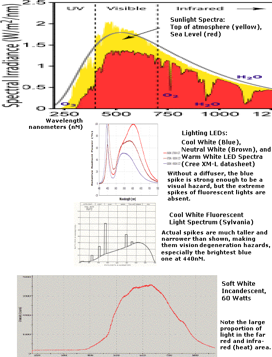
All the lights look
different than sunlight. The violet and blue end of the spectrum is
missing in the incandescent. Evidently all fluorescents have a nasty
big blue spike right at 440 nM (mercury vapour) and some other spikes.
(Cool white fluorescent has been banned in some jurisdictions,
especially in school classrooms.) Then the main range tends towards
reddishness.
LED lighting is of course quite new. It doesn't have
fluorescent's spikes. Ultra-violet and violet are missing, then the
blue of the actual emitter is prominent. But then it's weaker in the
cyan from around 475 to over 500 nM. Above that, the phosphor gives a
broad band, then the far red end is very weak.
But I tried looking at some reddish objects under an
incandescent and an LED light. One in particular, a tab of the colour
from a magenta toner cartridge box, looked rather brownish under LED
and brighter red under the tungsten. Aha? However, the next day I found
it looked brownish in daylight - even here the LED was the truer colour.
I ordered a few coloured emitters (red, green, blue) to
experiment with, to try and fill in weaker bands and see how I like the
light. However, those seem to be colors already well covered by the
white. An indigo (far red) emitter (eg, 675 to 725 nM) might make it
extra pleasing, and perhaps with a cyan at 500 nM the spectrum would be
very even through the visible range except in the far violet. I see a
cyan emitter listed at Cree in the XLamp7090XR series, but not indigo.
I also didn't see the cyan at DealExtreme.com, so I'd have to track
them down.
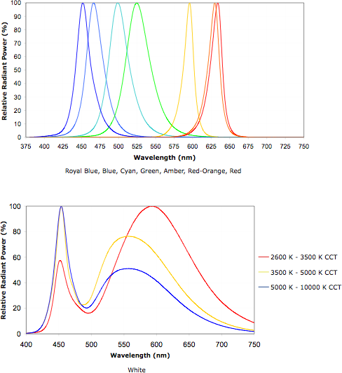
Some coloured and white LED emitter spectra
But I must say that it appears any improvements would be
minor. White LEDs through a white diffuser are the most even, whitest
artificial light available. An incandescent light now seems a touch
drab and orangey to me beside a good LED one, even if it does activate
my solar powered calculator from about the same distance.
Turquoise Battery Project
I gave up on the first permanganate/nickel - zinc cell.
The
case was all cracked up, and it wasn't performing or improving. I
decided to re-use a previous case, which was in good condition, and
dug out the electrodes. On something of a whim, I decided
to try out the vanadium electrode from that case (which I extracted
mostly intact) with the zinc.
The culprits in poor conductivity
Trying to measure the resistance of the used vanadium
electrode, if it didn't read as being open or negative resistance, it
was
many kilohms. When I made it it measured around 50 ohms. Here may be a
good
clue
as to the poor conductivities: perhaps either with wetting or with
charging, or both, the positrode (or both electrodes) swells and the
conductivity
drops drasticly. Perhaps I need to put more graphite powder in these
electrodes to account for this, perhaps compaction is insufficient, or
perhaps there needs to be nowhere in the cell for it to expand to once
wetted. With dry cells there's
nowhere for the compacted powder to expand to, whereas I just have some
sponge rubber pushing the electrodes together. One or both can "fluff
up" if they want to, inevitably losing their good conductivity. This
would indicate that I should modify my construction.
Measurement of the nickel/permanganate electrode disclosed
that it was megohms from the surface of the electrode to the terminal
post. That must be the reason for the poor cell performance.
Measurements from one spot on the electrode to another varied wildly
(as usual), from ones of kilohms to megohms. The nickel negative,
however, still had very low resistance, tens of ohms. (As it was
removed from the cell, measurement to the separated post wasn't useful.)
Evidently the positrode is the problem, but in this case
much worse owing to poor connection to the post rather than just
swelling.
This was the electrode where I'd coated the surface of the plexiglass
with grafpoxy, then pressed the post in from the outside and the
graphite sheet onto it on the inside, expecting great conductivity,
which it had when made. If I pressed on the electrode where the post
was, resistance would drop to about 1K ohm. Evidently something has
delaminated - so this aspect of the construction also needs to be
modified.
Later I did more checks on the vanadium. I pounded it with
a hammer to try to "un-fluff" it. It didn't seem very fluffy. I found
that the new meter was giving pretty weird results, and the
conductivity within the electrode probably wasn't as high as it seemed.
Then I found that like the other one, the resistance to the terminal
post was high, tho not as bad.
V-Zn cell (~~2.3 volts)
Notwithstanding the high readings on the vanadium, the
cell performed far better than the previous one, and on a par with
previous best results. 25x better? Another 50x again and it would be a
real battery.
Open circuit V-Zn cell voltage was around 2.3 volts.
It's hard to be exact as it still had high self discharge and dropped
from 2.4 to 2.25 over a few minutes while I watched. Less Sunlight
dishsoap in the positive next time, and none in the negative!
Grafpoxy 'plating' of metal electrode structures
Another idea struck me as to electrode construction: if a copper or
other metal grille were simply coated with graphite-epoxy, would it not
be immune to the electrolyte? The part of the terminal inside the case
would also be coated, and of course the opening sealed. This might
provide a better electrode collector and terminal post, of simpler
construction. It could be to a salt electrolyte cell what nickel
plating is to alkaline cells. This construction would count on the
'grafpoxy' being completely impervious to the electrolyte, and on
obtaining 100% coverage that didn't get scratched or abraded away at
any point. Epoxy is very sticky and tough, so for the moment, I'll
assume these conditions can be met and try it out. I've become
convinced this is the way to do it if it works.
Some Conclusions
By October 3rd, I figured I had a pretty good idea of
where the main problems lay. After running a discharge test that day
for seven hours, I remembered how running off to record the latest
battery every little while reading disrupted the process of working on
anything else. (An automated data logging system would be most
helpful!) So I decided to drop the battery experiments for a while and
work on other things.
I need some way of making cells that can hold the positive
electrodes compacted as well as hold pressure and not leak. Doubtless
better initial compaction is required. Probably metal structures coated
with grafpoxy can serve as electrode elements, which will simplify
things and - I trust - provide good conductivity.
I might end up with something like cylindrical cells with
wrapped up electrodes after all, as is done for NiCd and NiMH dry
cells. I'll pause and consider all this, and perhaps some
inspiration(s) will strike as to improved ways of achieving the several
goals. Or I can see making cylinder cells with coated grills and the
ingredients simply forced [pounded?] in like cheap dry cells. A 5" long
piece of the PVC irrigation pipe I've been using for NiMH battery
sticks might make (without detailed calculations) a 30 to 60 amp-hour
cell.
When I have cells that actually work, then it
should be time to try out some of the chemical refinements that I've
been trying all this time with poor results, owing to trying them in
cells with very high internal resistances.
Zinc: Best Negatrode in Salt Solution?
Zinc is in some ways a great battery negatrode. The
reaction voltage is about as high as will work readily in water, and
the oxide or hydroxide is a relatively conductive semiconductor, so it
doesn't tend to become passivated.
I knew zinc oxide or hydroxide dissolves in common acids,
and I had read plenty about how it temporarily forms soluble zincate
ions in alkali. The soluble forms migrate, degrading the electrode and
causing poor cycle life - the bugaboo of attempts to make 1.6 volt
nickel-zinc rechargeable alkaline batteries, as well as acidic ones.
(My
nickel-zinc in oxalic acid experiment seemed to work - none of the
charge and discharge products are supposed to be soluble in oxalic
acid. But that was just a short term test, and the 1.45 volts potential
was lower than expected.)
The 'known' solubility problems of zinc steered me away
from it, and led to my unsuccessful attempts to make a manganese
electrode with egg albumin to raise the hydrogen generation voltage -
which would be a fabulous negatrode if it can ever be made to work.
But now I read on Wikipedia that zinc oxide and hydroxide
are
both "virtually insoluble" in plain water at ordinary pH. This leads to
the thought
that ordinary cheap old zinc might after all - possibly - make a
long-life
battery electrode rather than one that
degrades with cycling, if the electrolyte is a salt solution.
This would imply that it must form the oxide or
hydroxide rather than zinc chloride (as it does in ammonium chloride)
as it discharges, and that the
zincate ion doesn't form at neutral pH.
I think it's worth making and trying out cells with
zinc negatrodes. If it works I'll have solved a problem that many
battery researchers have struggled with. Perhaps rechargeable NiMn-Zn
can make the cheapest
long life batteries ever, at about 1.9 to 2 volts potential. Or V-Zn
for that 2.2 volts!
We can guess that zinc in salt solution will react at about -1 volt,
and that the final discharge compound formed will be ZnO or Zn(OH)2.
But will that nasty Zn(OH)4-- ion form?
A Zinc Positrode?
There's another surprise: On going to WebElements.com to
get the above chart, I note on the page that evidently zinc can form
zinc peroxide, ZnO2, a substance I hadn't heard of. One way to form it
is by reaction of zinc oxide with hydrogen peroxide -- which implies
that it doesn't immediately discharge back to ZnO in water. But info is
limited. Wikipedia has little to say, and the electrochemical charts
don't show that such a compound exists - because they don't consider
salt electrolytes. The three most important questions are: Is it
soluble, is it an electrical insulator, and what is the reaction
voltage?
If the answer to the first two questions is "no", and if
it has a useful reaction voltage, zinc might make a good positrode in
salt solution as well as a negatrode. I've never heard of this before,
which suggests it probably won't work or is impractical, but hey you
never know - it's worth checking out.
The obvious way to try it out is to make a cell with two
electrodes of zinc oxide... the oxide is the discharged state for both
electrodes.
Neg: ZnO + H2O + 2e- <=> Zn + 2 OH- @ -1 volt
Pos: ZnO + 2 OH- <=> ZnO2 + H2O + 2e- @ +? volt
The zinc valence in the peroxide is still 2, so it must
have single bonds between each of the three atoms. Interestingly, it
looks like the water should be in balance charging and discharging.
More Experiments (from Oct 9th)
Finding that the main conductivity problem seemed to be
between the electrodes and the terminals, and having distanced myself
from the problems for two or three months, I realized that if I could
make a grafpoxy coated metal grill as an electrode substrate, I could
also have coated leed wires soldered to it, eliminating the carbon rods
and the graphite sheets entirely.
Such a promising improvement was just too tempting to put
on the back burner for some other time. I made too much grafpoxy (hard
to control epoxy flow in x1 grams quantities), so I made several coated
copper grills with various terminal wires or brass bolts. One I put
into the good case (after dumping out the vanadium electrode) and
sealed the hole where the wire came out, with more grafpoxy. I put the
vanadium and the zinc back in, but it didn't work well. I decided it
was time for a completely new cell.
Then I wasn't looking forward to trying to put the grills
with the copper wire sticking out the middle at right angles, into the
compactor. But if I tried to attach them to the electrodes afterwards,
they'd probably turn out like the vanadium. Then I realized making them
with the wire sticking out sideways offered advantages: the compactor
would take them, and the cells would sit flat with no wire coming out
the bottom.
So I made some new ones. Then I thought to simply clip the
wire off some I'd already done, scrape an area of the screen in a
corner, solder on a new wire, and recoat the bare areas. After that I
had 8 grills ready.
New Cell
I found an acrylic case with thinner walls that I'd made
earlier, and I decided to go with that and lots of 'stuffing' to keep
the electrodes from fluffing up. So then it came down to filling it. It
might burst or leak under pressure. First I had to get far enough that
that would matter.
Cell Internal
Components
Positive:
* Graphite Sheet
* Briquette:
10g monel mix (instead of just Ni(OH)2)
3 g KMnO4
10g graphite powder
.25g Sunlight dishsoap
.2 g Sb4O6
2.75g Diesel Kleen (slightly too wet)
* Mixed. (Tamped down, resistances read around 10-15 ohms)
* Calcium oxide layer sprinkled on grill
* Compacted (with grill)
* Painted on calcium hydroxide layer
It made a 3.5mm thick electrode with no left overs.
However many hundreds of ohms the grill by itself read,
the finished electrode read under 10 ohms - mostly about 5 - from
random points on the surface to the terminal wire. This bode well
indeed for the finished product! In fact, it would seem I could use a
little less graphite, maybe about 1 to 1 by weight with epoxy, and the
mix would flow better and make a thinner, more uniform coating.
I put the trode into the case and grafpoxied around the
leed hole. Later I realized I had
forgotten to bake the electrode in the oven 80' at 110ºc and then
torch it. Oops! Too late now.
Separator:
Microporous cellophane painted with acetaldehyde with osmium dopant
Arches watercolor paper painted with zircon
Negative:
Zinc sheet from a standard dry cell, copper foil soldered to an edge
that sticks up above the electrolyte.
Figuring out the amp-hours is simple: it weighed about 5 grams, and
zinc is .820 amp-hours per gram - 4.1 amp-hours. Attaining this figure,
however, would mean turning the entire zinc sheet into oxide. Ideally
one might use zinc and zinc oxide powders mixed with graphite etc, with
an enclosed grafpoxy screen. The zinc sheet with a soldered on leed is
just plain simple for experimenting.
Electrolyte:
H2O with KCl and borax
The next day (13th), I made
the usual flat cell, per above. It was very thin with only a 3.5mm
electrode having an internal collector, the separator, and a thin sheet
of zinc. I think the space would have held four such cells!
The 'prismatic' cell idea comes to mind - alternate layers
of "+" and "-" all tied to the same terminals. Instead of maybe 25 mA
holding good voltage (as it turned out) it could put out 100 for quite
a while. Put enough crappy batteries together and you've got a good
one. If it wasn't for the difficulties of connecting the electrodes
together in a case with electrolyte that attacks metals, I might try
it. But perhaps I could solder up the connections and then coat them
with grafpoxy, or even just epoxy.
Back to the plot, I put in two pieces of 5mm ABS plastic
above the top electrode to take up space. Thus there's more solid and
less elastic layer, but the positrode could still swell up if it pushes
very hard. I'm counting here on the problem having been more the
contact between electrode and collector, which I trust should be
greatly improved.
The open circuit voltage, initially about 1.3 volts,
seemed to be about 1.8 volts after some charging, maybe .4 volts lower
than V-Zn.
It seemed I could put considerably more charging current
into it without the voltage getting pulled too high. After a few hours
of charging, it could momentarily put out an amp of current into one
ohm (at one volt, obviously). That's just 35 mA per sq.cm interface
area, but on a par with my best. But my previous best cells would put
out less and less over a few days. (I should have taken them apart,
dried them out, and re-checked electrode conductivities then - I'd have
found the problem sooner!) Would this one deteriorate as well, or stay
the same? In a load test the same evening, voltage still dropped pretty
rapidly with a 25 ohm load. It was below a volt after 25 minutes. But
it hadn't really had a lot of time to charge yet. Again, the zinc side
must have been pretty much charged to metal when I put it together, but
the NiMn side didn't seem to be charged. I used KMnO4, but the nickel
would
have been in a discharged state and probably would have discharged the
Mn to MnO2, so it might take some charging, or some cycling, to
(hopefully) balance them out.
I then opened the case. To try and increase the surface
area of the zinc, I sprinkled a little zinc powder on the separator
sheet, and then put the zinc sheet back on top of that. And I added a
bit of water with dilute potassium chromate chloride - might improve
electrolyte ion conductivity?
I didn't see any immediate notable changes from these
experiments - perhaps a slight rise in conductivity.
The next morning, the cell started a 25Ω load test at 1.74
V open circuit, and dropped only to 1.64 after 30 seconds under load.
It held above 1.5 volts for 7 minutes. Just as it appeared to be a real
battery, it started dropping rapidly and by 12 minutes it was down to
1.20. Then the drop virtually ceased and it held over 1 volt to the 35
minute mark, 10 minutes longer than the first night. I attributed the
rapid drop to the various charge states of the mixed manganese and
nickel, thinking that perhaps overnight it had charged up a small
amount of MnO4- or NiO2, and that when that was exhausted the voltage
dropped to the MnO2 level.
A longer - or faster - charge before another test might
tell more. I put it on at 53mA instead of 33. But before that, I opened
the case again and added some more (KCl) electrolyte and a few tiny
drops of methylene chloride - this time an organo-chloride.
I found the cell leaked - from where I'd heard a "crack!"
sound as I did up one of the case lid screws. I turned it up on end. I
also read that zinc gradually forms an insulating zinc carbonate
layer when exposed to air, which tends to passivate it. I thought it
was just oxide, the discharged state. Evidently I should have buffed it
off before I put it into the cell, and the zinc powder, having been
sitting in the
air, would be of little use, at least initially. This could be part of
the reason for performance being initially poor but improving over time.
Whether from the charging, the additions, or both, by
early afternoon the time the cell would source an amp or more into a
one ohm load rose from "a moment" to about ten seconds. I'm pretty sure
that makes it my best cell yet. A third load test in the evening after
a long slow charge was about the same as the morning except that all
the times were about 2-1/2 times longer.
The 15th was a little better, but I added some more
electrolyte and the case cracked in a couple more places. An evening
test marginally surpassed all previous, but green puss - I mean
saturated nickel and copper oxides - was oozing out the leaks.
Looking in at some of the greenish substance through the
clear walls disclosed the
random lamilar structures formed with the black graphite when compacted
with "Diesel Kleen" solvent (which seems to dissolve graphite) to
provide random conductive paths through the
electrode, which really helped conductivity within it - tho evidently
not to the previous graphite sheets and terminal post. These are pretty
much
invisible when the electrodes are first made and all is black. I
tentatively atribute the effect to the 1,2,4trimethylbenzene in the
Diesel Kleen, but other of its chemicals may well also be involved. I'm
really no chemist and especially not an organic chemist, and this is
but a conjecture.
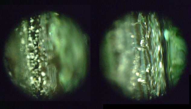
Random dark lamilae - "ribbon" layers -
of graphite within greenish
oxides at 10x magnification.
(Electrode was compacted left-right in this view.)
Some areas showed more random "squiggly" black lines.
(eg, the out of focus area on the right side of the left image.)
The maximum current into a 1 ohm load didn't go much
higher, perhaps 1.3 volts momentary dropping to 1 volt after 12
seconds. A standard D cell I tried gave about 2 amps driving over a
volt (.5 ohm load), and lasted somewhat longer. The zinc sheet in my
cell is about 1/2 the surface area of the D cell's, and I infer that
the limiting factor is the limited surface reaction area of the zinc
sheet. The next thing to try (probably after making a new case) will be
to use compacted zinc oxide powder in a porous electrode similar to my
others. If the theory is correct, current drive may be substantially
higher.
Another thing to try will be to vary the proportions of
KMnO4 and NiO2 (or monel) to see what gives the higher voltages longest
before they drop to a lower level.
And as always, to try and improve the quality of the
construction. It's not much use if it leaks, the separator sheet
shorts, the current collector corrodes away, etc.
I couldn't resist doing a bit more with this cell before I
got around to making another. The fifth discharge test ran out a little
sooner. I figured this was because it was running short of water with
the leaks, so I opened it and added some, and also a just couple of
drops of toluene. (Nevertheless the wall of the case cracked in several
places over several minutes next to where I'd dripped in the toluene.)
Since it didn't happen immediately, I guess the toluene must soak into
the acrylic and cause it to swell. It's still a pretty hard and brittle
plastic, so the expanded area cracks against the unexpanded.
Whether because of more water or the toluene, the current
drive increased. Into a 10.7 ohm load, it stayed over 1.5 volts for 10
minutes. A 1 ohm load held over 1.0 volts for 30 seconds instead of 12.
Remaining Issues
The self discharge, while now
spread over hours rather than minutes as in my earlier attempts, is
still too high for a practical product. It needs to be slowed to days
if not weeks. Months would be better.
Current density could be better, tho it's already not bad.
The electrode surface interface area in my test cell is about 25 sq.cm.
- half that of a simple D cell. The max current of 1.2 amps into a one
ohm load gives: 1.2A/25 sq.cm = 47 mA/sq.cm. To maintain good voltage
however, the current density is
at best around 20-25 mA/sq.cm. of separator. That's in the right
ballpark - around that of a
standard
dry cell.
Calculating this out surprised me - I thought an amp max
was pretty poor, but it's mainly because the cell is small. The case is
after all mostly filler and the battery is a thin layer on the bottom.
However, attaining the 40-50 or more achieved by alkaline
cells - or better - would be nice. (A
zinc-air cell has the best figure I've seen: 200 mA/sq.cm.)
I have yet to determine the theoretical energy density. I
have little doubt it's higher than lithium ion, but nothing like that
is being achieved at the moment. In this cell, the zinc sheet needs to
be replaced with a proper powder electrode, as only its surface layer
gets used, giving a whopping .1 AH or less at ever decreasing voltage.
(Other batteries I've made have given near an amp hour, but at very low
voltages. In the
standard dry cell, the surface of the zinc is continually eaten away by
becoming soluble zinc chloride, so much of the zinc sheet is gradually
used.
That's why it doesn't recharge well. Here we form insoluble zinc oxide
at the surface,
and the thickness of the sheet behind it is unused.)
The grafpoxy grills work! They are the great enabler for
salty battery chemistries. I think a new cell with two proper
electrodes and (sigh!) no leaks is the next step.
Real Zinc Negatrode
On the 20th I decided to make a "real" zinc electrode and
stick it into the same leaky battery cell.
20g calcined zinc oxide (13 amp-hours worth)
5g graphite powder
.25g Sb4O6
.25g Veegum (bentonite clay mix - binder)
4g diesel kleen
Tamped down in the mortar this was around 50 ohms. It was
something of a pliable putty consistency, but there was a bit much
diesel kleen and over 5 grams oozed out of the compactor. That left
something like 11 amp-hours potential. That would depend on very
thorough utilization, being able to get the electrodes into balance
with charging and discharging, and that the other electrode has at
least the same capacity.
Then I looked at the leaky, cracked battery case and
decided to make a new one and to try to pull the positrode out intact
and reuse it. I broke off the sides, but when I pulled at the
positrode, it fell apart near the terminal wire. The rest of it seemed
hard as a rock - an excellent electrode briquette. I had noticed, on
close inspection, small bare areas of copper or solder showing on all
of the grafpoxied grills. Many of them were in fact next to the
terminal wires. (Perhaps remnant solder flux kept the epoxy from
adhering.) It doesn't take much of a bare spot - corrosion will rapidly
spread until the cell quits working.
Grafpoxied grills are doubtless still the key, but it
might well pay to use less graphite to get better flow and smoother
coverage, even tho the conductivity would be reduced. It might also be
necessary to do two coats. Rinsing and brushing the grill after
soldering might also be valuable - or even some exhaustive cleaning
process such as those used before electroplating.
So I made another positrode as well, out of about 25 grams
of Ni(OH)2 and KMnO4 mixed last January. I didn't do much measuring. I
added too much diesel kleen as usual. This time I forgot to add
anything as a binder - I had meant to put in a bit of Veegum. Instead I
remembered both to put on calcium oxide and to torch it this time for
the 'limestone' toughness. Sigh - seems I just can't remember
everything. Trouble is I make electrodes so seldom amongst all the
other projects, and it's often not obvious if something's missing or a
step has been skipped... okay, I've written up that checklist I've been
meaning to make and taped it up inside a cupboard door.
The zinc electrode, puttylike before compaction, proved
unexpectedly crumbly and had
lost some of its substance by the time it was seated in the cell.
The cell didn't finish charging - it hardly lasted a day.
The copper grill dissolved into blue powder and the electrode fell off.
The grill from the first cell, however, seemed largely solid except
near the terminal wire. There was a blueish tint to the briquette right
next to the grill wires, but that may have been the electrode's
nickel/monel substance charged to oxide or hydroxide rather than copper
oxidizing from the grill. (It would be helpful if copper and nickel
oxides weren't virtually the same color!)
On the
25th I made some new grills, clamping flat pieces
of copper foil (garden shop?) over the copper grill (Opus Framing -
artists' supply, where I also get the graphite powder and the Arches
watercolour paper) with small rivets (Tandy Leatherworld).
I used 1 to 1 mix of graphite to epoxy. After setting the
epoxy in the oven at 65ºc for an hour, while preserving the
remaining epoxy in the freezer, there were some small spots of bare
copper visible, and I went over them with a second layer. Close
inspection with the angles and light right the next day revealed there
were still some tiny bare spots.
Much as I wanted to get going and put a battery together,
they would still dissolve, so I mixed some more grafpoxy and went over
the spots with a paintbrush. With leftover grafpoxy I went over copper
spots on a few of the previous grills as well. In the end it was four
applications. Then there was too much grafpoxy on some of the terminal
strips and they didn't fit in the compactor. I carefully filed some
off, but struck copper both times and had to do yet more grafpoxy.
Then, with the terminal strips and all the grafpoxy added, only one of
the grills fit in the compacter.
I'm wondering if something else might substitute for the
epoxy. "Grafwax" might work well: melt the wax, mix in the graphite,
and then just dip in the grills. But wax is pretty soft and surely
wouldn't withstand compacting the electrode around it. Maybe some
plastic that one could melt and dip the grills into? But that doesn't
seem to exist.
A dip of ABS dissolved in methylene chloride and mixed
with graphite? Ugh! Hmm. It might work. At least it's harder
than wax... and more flexible than cured epoxy.
And just for variety, I have a little of the #60 stainless
steel grill left, and some aluminum window screen. As long as it's
protected and clamped to the terminal with rivets, it shouldn't matter
very much what type of metal the grill is. The fine stainless mesh
should give the most contact points with the electrode substance, which
might perhaps provide higher current capacity per unit area, especially
with a thin electrode - unless the grafpoxy plugs the tiny holes.
I took the remaining Monel-MnO2 powder made in April (27g,
TE News #39) from the back of the counter and added 8g of KMnO4 and 5g
of graphite, total 40g. Then I added 5g of diesel kleen and compacted
it. It made a fat 6mm briquette, and the resistance was 15-20 ohms from
any surface point to the terminal. (Pretty amazing when the layer of
grafpoxy left over on the plastic sheet measures 20000-100000 ohms!) If
the grill doesn't dissolve, it'll be a great electrode - good current
and surely over 10 amp-hours capacity.
Carbon Nanotubes
Evidently carbon nanotubes help a lot with increasing
conductive surface area at the nano scale, increasing the efficacy of
the active elements. Reading in Wikipedia/Toluene (methyl benzene):
"[Toluene] is used as a solvent to create a
solution of carbon nanotubes." Perhaps
if one simply added toluene to an electrode with all that graphite in
it, carbon nanotubes might be formed as it evaporated? So this time,
rather than adding it to the
electrolyte, I dripped a few drops of toluene onto the electrodes
before putting them into the battery, and left it to evaporate. Of
course, I don't know if that will actually work... but it probably
can't hurt anything.
The battery didn't perform very
well and gradually got worse. I took it apart at the end of the month,
and this time it was the zinc negatrode grill that seemed to have
degraded. This I had salvaged from cell #2, and there were doubtless
gaps in the grafpoxy. I also think if I make and use some zinc powder
(and keep it sealed this time so it doesnt form zinc carbonate) it'll
work better than just using zinc oxide.
The electrodes slid out more easily through the open side and could
then be separated easily. This is definitely a better case style. I'll
be putting it back together with a new zinc side in November. But I
went to get more 1/2" acrylic plastic and some 5/8" and 3/4", but they
only had 3/8".
I'll also be trying out some more electrolytes in November.
http://www.TurquoiseEnergy.com
Victoria BC