Turquoise
Energy Ltd. News #46
Victoria BC
Copyright 2011 Craig Carmichael - December 1st 2011
http://www.TurquoiseEnergy.com
= http://www.ElectricHubcap.com
= http://www.ElectricWeel.com
Month In Brief (Summaries)
* I'm to speak at Discover Tectoria
conference Dec 8th, about Electric Hubcap motor system
* In passing: Nuclear Industry Melting Down; Buying Police Loyalty;
Yet Another GM Dirty Trick
Electric Hubcap System
* Motor repairs (working again) & improvements to rotor compartment
* Polyurethane spray paint "crust" to keep ilmenite coil coatings from
flaking off.
* Motor controller: V2 boards, CRM = direct torque control, great
current
control during regen... but how??
* Cutting shaft keyway slots with a lathe - lathe as milling machine?
Electric Weel Motor - no report (I
did coat the coils with ilmenite. Very flaky, unfortunately.)
Mechanical Torque Converter Project
* New
design: Magnetic Impulse torque converter
- simple, robust, no wear, no internal moving parts!
* Combo magnetic/mechanical design offers higher torque
Sprint Car Conversion Project - no
report
* Working on components - see Electric Hubcap System, torque converter
and NiMH battery projects
New Electric Hubcap Outboard Project?
* An outboard from scratch might be just as easy as a conversion - and
better?
* Production kit version?
LED Lighting
Project
* Bright, cold white emitter fixtures: 1100 lumen/15W
* Electric bills continue lower than expected into winter (yay!)
* Energy Star partnership agreement form file format problems
NiMH Battery Project
* Ultimate Battery Stick? - 4" PVC pipe holds 7 sets of D cells... a 4"
x 25", 12V, 70 amp-hour battery
* Car(s): Musings about using combos of NiMH and lead-acid
Turquoise Battery Project
* Zinc powder?
* Zinc powder from zinc oxide
* Best quality zinc electrodes!
Newsletters
Index/Highlights: http://www.TurquoiseEnergy.com/news/index.html
Construction Manuals and information:
-
Electric Hubcap Motor - Turquoise Motor
Controller - 36 Volt Electric
Fan-Heater
- Nanocrystalline glass to enhance Solar
Cell performance - Ersatz 'powder coating' home process for
protecting/painting metal
Products Catalog:
- Electric Hubcap Motor Kit
- Sodium Sulfate battery longevity/renewal
- NiMH Handy Battery Sticks, Dry Cells
- LED Lighting Products
Motor Building
Workshops
...all at: http://www.TurquoiseEnergy.com/
(orders: e-mail craig@saers.com)
November in Brief
I'm to Speak at Discover Tectoria,
December 8th
Late Breaking News for local Victoria BC people: On
December 1st I was invited by phone to speak next Thursday (Dec. 8th)
at the all-day Discover Tectoria conference and trade show
[http://discovertectoria.com/], known in previous years as Island
Tech, on the Electric Hubcap motor system. I'm among
several speakers expected to speak for about 10 minutes each sometime
between 2 PM and 3 PM. I don't have all the details yet, but I'd like
to bring in a motor, controller, a couple of battery sticks and
C-clamps, and run it on a table as a demo and point out features.
Discover Tectoria will take place:
Thursday, December 8th at:
Crystal Garden
713 Douglas Street.
Victoria, B.C.
The entry fee to Discover Tectoria is $20, but
there are supposed to be some free entry coupons in the newspaper this
week.
The Month
In some ways,
the first half of November felt like one of those dreams where
you seem to be trapped in
slow motion and can't get anywhere. There were days when virtually
nothing seemed to move forward. On the other hand, I spent a lot of
time on the internet doing various promotions. Then from the 16th or
17th to about the 20th good things started coming together bang bang
bang. Then it went back into slow motion.
Everything in its
place... I
decided that on the Sprint conversion that the next thing to do was to
fix
the motor. In the process I'd also further the motor development: I'd
make
a mold to improve the rotor compartment rim. It's safer: not only much
thicker and tougher, but the attachment bolts won't be
exposed inside, to be hammered, and bent and ripped out by any
magnet(s) that
might potentially come loose. The last arrangement was too easily
damaged with potential for inflicting serious
injury.
By then
maybe the IR2133 motor controller V2 boards would arrive and I could
make the motor controller. With a working - improved - motor system
again, it would be
time to tackle the torque converter.
Considering installing the Sprint batteries, I came up
with the idea of Super Battery Sticks: a single 4" PVC drain
pipe, with 1-3 struts glued in for battery alignment, will hold
7 parallel strings of D cells, eg, 840 WH at 12 volts. And they'll only
weigh about 30 pounds, mostly the 70 D cells themselves. Three of
these would fit
where the car's radiator was for 36 volt, 2520 watt-hours and plenty of
amps,
for about 1400$ at the current cost of the cells.
And I'd see if I
could convert three of the ten 12.0 volt, 5 amp power adapters I got
(at XS Cargo for 3.99$ each) to 13.8 volts, to constant-voltage charge
them.
It would be even cooler to put three 65 watt solar
collectors on the roof, regulate them to 13.8 volts, and not even have
to plug the car in when I'm not doing a lot of driving -- but that'll
have to await some time when I have money.
For a couple of days
I considered that maybe I should do
some contract work for someone to earn some money. I was thinking
something short term, part-time, but I knew it was more likely either
to come to naught or grow into a lengthy commitment that would pretty
much displace the inventing. Personally I consider the
work I'm doing to be more valuable to all than anything I could do
for some one concern, but it would be nice not to have to wonder how
far
into debt I'll be this year before I get the annual pittance
next spring or summer that society will actually give inventors to work
on new
things, or wonder about how to do increasingly urgent repairs on a low
budget, such as
going up on my high, 45º roof myself to replace "30 year" shingles
that are falling apart and blowing off after only 18.
On the 17th, the day I (finally) finished the rotor
compartment rim mold, I thought up a Magnetic Impulse Torque
Converter. This is in principle a magnetic version of what I was
planning to make mechanically, with supermagnets tugging at aluminum
'spokes' or 'arms' for only a short part of each rotation. It's an
exciting design: no moving
parts, nothing touches anything else to wear out - it's simple and
looks easy to make! An experiment indicated the magnetic forces
strength should be in the right ballpark -- unless things saturated
electromagnetically somewhere below car moving force. I decided to make
one for the
Sprint instead of
finishing the mechanical one. But the torque increase wouldn't be all
that high, and by the end of the month, still before I was ready to
start working on it, I decided on several changes, and then to make it
a combo magnetic-mechanical one that would have more kick to it. I'm
keeping the pieces for the original mechanical converter design just in
case.
The Turquoise battery project seemed to devolve down to
looking for zinc powder. It's there on e-bay and other places, but
American sources don't want to ship it outside USA, and Canadian
sources don't return e-mails. I ended up grinding a little myself,
which was tedious, and then got onto the other things without making an
electrode.
I tried another type of LED emitter, making an 18 watt,
1100 lumen fixture. These ones are 'cold white', which looks rather
bluish. They'll be about the cheapest per lumen price-wise. They're
also 12 volts, so no matter how many emitters I use in a fixture, it
will be that voltage with no need for 6V, 9V or other power adapters. I
may do these, and nothing but four-emitter Cree fixtures (3V each), and
use 12 volts exclusively. Only on the last day of the month, after a
couple of weeks of hassles with some new PDF file format that my older
computer and software wouldn't handle, did I get the Energy Star
Partnership application form off in the mail to begin the process
of obtaining Energy Star ratings and BC Hydro rebates for
potential LED
light fixture customers.
In passing: Nuclear Industry Melting Down; Buying Police Loyalty;
Yet Another GM Dirty Trick
Switzerland is next to eliminate their potentially
devastating ticking time bombs - they've legislated shutdowns from 2019
to 2034 to bring nuclear power generation to an end in that country.
(Now there's a country that could well string windplants like cable
cars between mountains!)
Michael Moore spoke on RT Times - I watched it on youtube.
He said he was setting up
cameras and (IIRC) crime scene tape in front of the bank (a week before
"Occupy Wall Street") to
do a piece on it, when a police officer came up. Michael tried to
tell him they were just shooting for a sci-fi, but the officer wasn't
fooled. He said,
"Go right ahead Michael, they've taken our pension fund too."
Evidently recognizing they'd committed one crime too many,
"the 1%" made a big "gift" to the NYC police dept. When an outraged
public is howling at your door - or occupying Wall street - it's best
not to have the police on the wrong side.
On the 25th I met a retired mechanic who had worked at GM
car dealerships up island in the 1960s-1970s. He told me that one day a
customer brought a brand new car back in, saying the gas gauge wasn't
working, because it still said "full" after driving 250 miles. He
looked under the hood, and where the carburetor usually was was a big
carburetor or something (he motioned over a foot or more square or in
diameter) with all kinds of hoses and connections. They phoned the
factory to find out more about it. Someone flew out from the factory
all the way to Vancouver Island that same day, removed the unusual
carburetor and took it away after installing the regular one.
There was nothing wrong with the gas gauge - the car had just used far
less fuel than usual. It was one of many demonstrations that answers
are all around us, but are being witheld. Needless to say, the new,
super economical
carburetor never made its debut in production cars. This disproves
GM's story that it wants complex cars that need lots of servicing
because that's its "business model". This carburetor was more complex
than the regular one, not less, so according to their own humbug
excuse, it should have been favored. In reality of course the same
gangster families control GM and the oil companies, and maximizing oil
consumption was and still is their goal - contrary to all interests but
their own lust to wrest the money from other peoples' pockets.
The active undermining and sabotage of every
transportation energy economy and alternative has held up vital
technology for a century now and is one of the major forces gradually
ripping civilization apart. It seems obvious to me that natural
resources should be owned by the public and administered on its behalf
by the government or
by a public trust, not owned by private interests for monopolistic
profit at the public's expense. That step and philosophy would get
things under public control, and I think we'd find that would get us
switching off oil - in years, not decades.
I think as the population levels off and competition for
land, housing and goods diminishes, as supplies become sustainably
adequate to the
demand, we have what we need to all be well-to-do with about 4 or 5
hours toil a day. Presently we can't achieve it because of the grossly
inequitable and rapidly worsening distribution of the wealth. That too
should be greatly improved by public ownership of natural resources.
Electric Hubcap Motor System
Motor Renewal and Improvement
On the 6th I repaired the magnet rotor. I made sure there was plenty of
epoxy and that the polypropylene strapping was well stuck down,
including brushing more epoxy onto the remaining seven magnets and the
material around them along with the five that came off like bullets.
It will likely withstand the RPMs that 42 volts can give
it
now, but I think I'll stick to 36 volts unless I find that has
insufficient
power in an actual use. Besides, it's easier charging three identical
12 volt
sections without an extra 6 volt section thrown in.
I was surprised in October's motor failure that the
outside rim of the magnet rotor had ripped open. In the second week of
the month, I started putting together a mold to make molded rims for
the rotor compartments. The molded rims are sturdier because of
thick, solidly molded walls. They're also safer because the wall
encloses the bolts that hold the rotor compartment to the stator, so
even in the event of a rotor failure, loose magnets won't hammer the
bolts to bend them and pry them loose from the stator plate. As one
more bonus, the compartment will be 1/4" thicker, 1.75" inside, and
things will fit more easily. I couldn't readily do that using the PP
strapping
because it only came 1.5" or 2" wide.
The mold has several pieces. Some of them had to be
machined, and what with forgetfully trying to shop for polyethylene on
Rememberance Day and other things (house and porch repairs), it wasn't
ready until the 17th.
 The next day I
'retrofitted' an existing rotor cover with
a new rim in the mold. It was tedious, but it was virtually a snap-on
fit onto a stator center ring. Great! It couldn't shift sideways a bit
and line the shaft up slightly crooked like before. It's now pretty
much "well done"
to sell in kits, where it had been a bit "cludjy" before. That didn't
mean it didn't need a bit of touch-up as there were spots of dry
polypropylene here and there. That should happen less for a new rim
than with stuffing cloth in thin spaces beside an existing thinner one
- and the work will go faster. The outside wall couldn't be filled much
and mostly looked the same as before.
The next day I
'retrofitted' an existing rotor cover with
a new rim in the mold. It was tedious, but it was virtually a snap-on
fit onto a stator center ring. Great! It couldn't shift sideways a bit
and line the shaft up slightly crooked like before. It's now pretty
much "well done"
to sell in kits, where it had been a bit "cludjy" before. That didn't
mean it didn't need a bit of touch-up as there were spots of dry
polypropylene here and there. That should happen less for a new rim
than with stuffing cloth in thin spaces beside an existing thinner one
- and the work will go faster. The outside wall couldn't be filled much
and mostly looked the same as before.
I have the idea it'll take about 300 grams of epoxy resin
and 75 of PP cloth shreds to do a rim properly from scratch.
A minor remaining concern is the ragged top of the lip
that fits over the stator center plate. I sanded it down but there are
gaps. For the next one think I'll try getting a 1/8" thick piece of
polyethylene to stuff into the top of the mold around the edge, and
fill the mold well... in other words, mainly just improve my technique
and see how that works.
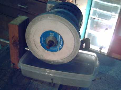
The thickened rotor compartment rim (before drilling bolt holes through
wall),
and the magnet rotor side of the center plate.
(Previous image shows stator side, with buttons to hold toroid core
coils in exact position.)
With various little things
like cutting a keyway slot in
the shaft, needing different length bolts, etc, it wasn't until the
29th I finally reassembled the motor, and it ran well the next morning
(after finding the coils were rotated one position from the sensors and
swapping phase wires).
I was surprised to find that it hit 1100 RPM with only a
12 volt supply. At 42 volts, that would be headed well up towards 4000
RPM instead of 2000. Yow! I'm starting to see why magnets might rip off
the
rotor. I think I'll take it apart and reduce the flux gap.
Cutting shaft keyway slots with a lathe - Lathe as milling machine
Uncertain about the long-term ability of the SDS
taper-lock shaft bushings not to move under conditions of high torques
and loads with vehicle vibration, and especially when the torque comes
in bursts, I decided it would be wise to install shaft keys. The SDS
bushings and the sprocket gear have keyway slots, but of course the 1"
round shaft, bought and then cut to length, is plain round.
In October(?) I ground a slot into a shaft for the torque
converter output and sprocket gear, and gouged it to final size with a
1/4" square "lathe tool", which itself became the final 1/4" square
key. But I wanted some way to do it properly, more easily, and
repeatably. I thought that properly, this needed to be done on a
milling machine with an end mill bit.
I hadn't even found
a 1/4" end mill on my
previous shopping trip looking for one. But in a "miscellaneous" can on
my own shelves I found
a genuine milling bit, that had
a 1/8" section and then a 1/4" section, bought cheap a few years ago at
a pawn shop to use just as
a
two-step "countersink" drill bit in wood. I cut off the 1/8" section
with the
angle grinder to
leave a 1/4" end mill. The end was a bit rough, but the sides would
mill.
 I phoned my
friend
who I'd bought the CNC machine from - never having done any milling, I
wasn't sure of myself. The speed of the router was way too fast, but I
wondered about the drill, if the drill chuck would hold
it square properly. Instead he suggested gouging out the slot with the
lathe using the tailstock and a 1/4" square lathe tool. That sounded
hard to set up and tedious, but I walked into the shop as we were
talking. Looking at it, I suddenly realized how it might be done
"properly" on the lathe.
I phoned my
friend
who I'd bought the CNC machine from - never having done any milling, I
wasn't sure of myself. The speed of the router was way too fast, but I
wondered about the drill, if the drill chuck would hold
it square properly. Instead he suggested gouging out the slot with the
lathe using the tailstock and a 1/4" square lathe tool. That sounded
hard to set up and tedious, but I walked into the shop as we were
talking. Looking at it, I suddenly realized how it might be done
"properly" on the lathe.
I put the end mill bit into the main 3-jaw chuck on the
lathe spindle. This would hold it securely and turn it at a
(selectable) lower speed appropriate for milling. Then instead of a
tool, I put the shaft itself in the tool holder on the turret, square,
lengthwise front to back. I put a 1/8" flat piece of steel under it to
shim it up to line the center of the shaft up with the bit. Left-right
adjustment would set the depth of cut, and screwing the turret
backward-forward would mill along the shaft.
After trying a few things, I found it seemed best to start
at the end of the shaft and mill out the whole 1/8" depth at once. An
end mill that would plunge (drill) properly might use a different
technique, and cut a blind slot that a key can't slide out of. I had to
hammer a crimp into the slot to ensure that couldn't happen. Later I
managed to sharpen the ends. Tho the four flute ends weren't even, this
would allow the mill to drill in for blind slots.
So there's one more motor making thing I don't need to buy
more equipment to produce!
It occurs to me that one might contrive to affix a small
drill
press vise that adjusts X, Y position with two screws, sideways on the
lathe carriage facing the chuck. Parts could then be fed up, down,
forward and back. With the turret to move left and right, one would
essentially have a small, sideways oriented milling machine. I must
remember that in case I have a need for one... maybe to make an
injection mold for making battery cases or LED light fixture bases?
Motor Controller
The V2 circuit boards from iteadstudio.com didn't arrive
in November, unlike the fast turnaround from AP Circuits. The low price
makes
it worth a considerable wait: assuming they come. After a month I'm
getting nervous.
On a discussion list, it appeared other motor
controllers
take their time going from forward to reverse, and some were talking
about them failing during braking - so much the better for mine!
Someone wanted one with
fast directional response for a computer controlled unicycle, so mine
was of
interest.
It occurs to me that the "Current Ramp Modulation" (CRM)
control is also "direct torque control", since torque is directly
proportional to current.
On the instant reversal, I've been idly puzzling in my
head why the control potentiometer works properly when the motor is
braking. CRM works by sensing when the current has risen to the set
level. But when it's braking, the current is flowing backwards, into
the batteries. It never occurred to me it might not work when I was
testing it, but the sense voltage should be reversed, negative...
shouldn't it? Yet the control works reliably and smoothly, seemingly
about the same as going forward.
Mechanical Torque Converter Project
New design: Magnetic Impulse torque converter!
On the 17th (just after I finished the Hubcap motor's
rotor compartment rim mold) a friend came by and we talked about some
things... including the resistance of aluminum to magnetic fields and
the potential uses of that. As he drew a thick piece of aluminum across
the magnets on a rotor, feeling the resistance to the motion: Eureka! I
had the
flash of an idea that's surely been on the
fringes of my consciousness for ages.
As I considered, experimented and
calculated over the next day and some, it became evident that it should
indeed be practical -- it appears to be the ultimate torque converter
concept that I've been groping
around looking for for the last 2-1/2 years.
For a mechanical torque converter, I've been trying to
have something impart 'hits' of torque to an output rotor. (I had good
hopes for the latest design.) For a
magnetic one, I've been trying to have magnets interact with aluminum
rotors, other magnets and pivoting magnets. I found various problems
with magnetic "hits" with magnets on
magnets, and magnets on an aluminum rotor causes a steady drag
that never gets up to vehicle moving torque.
I've thought at times of various 'out there' ideas
like
incomplete-circle gears, so that
the motor can pick up momentum in the gaps, then impart that momentum
to the output in the areas where the teeth mesh. But if the mechanism
stops where the teeth
engage, the motor won't be able to start turning. That leads to adding
a centrifugal clutch. It all promised bizarre, complex mechanical units
that would (at best) wear out quickly. (It's how so much of our
technology is cobbled together...)
What finally hit me was the idea of having rotating
aluminum blocks rather than a complete round rotor. The rest
of
the rotation, the motor would spin freely and pick up speed. Since
aluminum isn't attracted to magnets, the arms would only be pulled
forward, just as the magnets passed by them. This gives the
"torque hits" of the mechanical designs, in a smooth magnetic form,
with no
moving parts except the rotors.
It can't be 100% efficient because the magnets do
slip
past the
arms, generating some heat. The higher the torque needed, the more the
heat. But I expect it would be very good overall. (It would be
really hard to make something half as lossy as a fluid torque
converter.)
The strength of the
interaction would vary directly with the relative speed between the
motor and
the output rotor. Since it drops
to nothing at zero speed, there's no force to prevent the motor from
starting
to turn. (Along with making the converter work, this goes a long way to
ensure against motor and controller burnouts.)
If (for example) the output had two opposite arms ending
in big blocks of aluminum, and there were magnets at opposite sides of
the
motor's rotor, the motor could freely pick up speed and momentum for
almost
180º of
rotation. If it tugged on the arms for about 2 inches of rim distance
as the magnets passed the aluminum block,
and then had 12 inches of free travel, it might potentially have about
6 to 1 torque increase.
The idea is amenable
to a number of different
configurations. First, it's reversible. Whether it's the arms or the
magnets that are driven, the coupling effect is the same. The driving
side needs some 'flywheel' inertia. On the motor side, this must be
added. Going the other way, the inertia is provided by the moving car
for regenerative braking.
Second, it can be done radially or axially. Flat magnet
surfaces naturally suggest axial configuration, but with a radial
layout
it might be easier to get a very small flux gap without danger of the
rotors hitting each other. And magnets on the inside of a rim aren't
likely to fly off it.
Then of course the number of arms, the weights, the unit
diameter, the width, the magnets and the interaction materials,
etcetera can all be adjusted.
All the parameters of
operation can be adjusted in various ways. If 6 to 1 isn't enough
torque increase, one could
increase the diameter. That would provide more free turning inches
before the arm and magnet met again, or in other words reduce the angle
where interaction occurred. It would also increase the torque by
putting the force farther from the axle. This ups the torque required
of the motor as well. Another way would be to have one arm and one
magnet instead of
two, so that the motor had a full rotation to speed up instead of half.
Still another way would be to use narrower magnets and aluminum pieces
that would effectively pass by and interact in one inch instead of two.
Then, the heavier
the motor rotors, the
less the motor would speed up and slow down in each rotation. At the
extreme of a weightless motor shaft, each interaction would just bring
the motor down to low speed without imparting momentum to the
output. Then it would speed right back up again. At the other extreme,
a heavy flywheel would impart energy to
the output while hardly slowing at all. It would of course be equally
difficult to regain the bit of lost speed. This is closer to what is
wanted, but how much weight is needed and desirable? The motor already
has a fairly heavy magnet rotor, but at high power this can be
accelerated and decelerated rather quickly. A heavy steel magnet drum
as the torque converter input would about double it - I'm going to try
that
as likely to be a good motor flywheel weight.
The amount of interaction
between the arms and the magnets
is important. If it's too strong compared to the motor torque, the
motor will again be dragged back down to low speed every half
rotation, and it won't be able to pick up good speed and store up
sufficient flywheel
energy between hits. If it's too weak, there might not be enough
interaction to
start the vehicle moving even with the motor running full speed. In
that case, the
motor wouldn't be working hard; it might spin rather freely. There has
to be
a happy medium somewhere. I think I want to see the vehicle start
moving at around 500-700 motor RPM on level ground and maybe 1200-1400
up a fair hill.
I'm not sure how much coupling is useful or
desirable. Reducing the interaction between arms and magnets is simple:
just increase the flux gap. Or use a smaller aluminum block on the end
of the arm.
This is what's needed if the motor just
can't get up much RPM even at a high 'throttle'.
But it seems more likely that even with a small flux gap,
there just won't be enough interaction at reasonable motor RPM. The
output
rotor doesn't get vehicle moving torque imparted to it. In that case,
other parameters need to be
varied.
Easiest, one can put more magnets at each position for
more magnetic poles, with bigger aluminum blocks. If the motor is still
over-revving without making enough output force, more arms and magnet
positions can be tried: four of each instead of two will double the
interaction strength, but will also only allow the motor 1/4 turn to
accelerate instead of 1/2 turn. All these steps reduce the maximum
torque
multiplication.
Another way is to increase the diameter - if the diameter
is doubled, so is the linear speed at the rim at the same RPM, doubling
the force. Of course, a new diameter means all new parts.
Finally there's putting multiple elements at each arm.
This would best be done with an axial configuration - interleaved
'fingers' of motor magnets and output rotor aluminum passing each
other. Two pieces of
aluminum,
one on each side of the magnet, would cause twice the interaction. If
even that fails, a second magnet and a third aluminum block will
further increase it. Any number
of magnet and aluminum 'fingers' can be added until either it works as
desired or the whole unit
becomes too wide
to fit where it's wanted. I don't expect it would require such extreme
proportions as to be impractical, but possibly it might need more space
than I've allowed for in the Sprint mechanism.
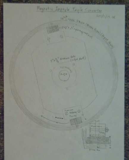
I did a drawing (below) using a radial flux design with a
brake drum rotor bought for a previous torque converter design that
will fit on an SDS bushing on the motor shaft, and a
piece of 5/16" x 5" aluminum bar for the output.
 I wanted to do
experiments, and I was thinking of making
jigs for them, but I came up with a simple way to test the
interactions. I set up the motor's magnet rotor (the motor still being
disassembled) in its casing so it could spin on one bearing with the
magnet side facing up. I put a piece of white tape on one of the 12
magnets
so I could see when it had done one revolution. With C-clamps and a
piece of wood, I set up a fat bar of aluminum (.75" x [1" to 2.5"
tapered] x 10") to sit right over the magnets on the rotor. I used the
fish scale to measure the pull on the bar, and the noisy wall clock,
ticking off
seconds, to estimate 60 RPM - one rotation per tick. I spun the rotor
by hand at roughly that speed and measured the forces.
I wanted to do
experiments, and I was thinking of making
jigs for them, but I came up with a simple way to test the
interactions. I set up the motor's magnet rotor (the motor still being
disassembled) in its casing so it could spin on one bearing with the
magnet side facing up. I put a piece of white tape on one of the 12
magnets
so I could see when it had done one revolution. With C-clamps and a
piece of wood, I set up a fat bar of aluminum (.75" x [1" to 2.5"
tapered] x 10") to sit right over the magnets on the rotor. I used the
fish scale to measure the pull on the bar, and the noisy wall clock,
ticking off
seconds, to estimate 60 RPM - one rotation per tick. I spun the rotor
by hand at roughly that speed and measured the forces.
I found that for good effect, the aluminum bar had to span
about two magnets width (~2.5"), presumably to span the north-south
transitions for rapid magnetic field changes as it passed over. The
thin end of the somewhat wedge shaped bar, still an inch wide, caused
surprisingly little drag. This suggests that two magnets should be
placed in each position in the drum rather than one, and the aluminum
blocks need to extend a little farther around the arc than I'd
expected. And the smaller the flux gap, the more the drag - it needs to
be pretty small, eg, preferably .05" rather than .15".
With the thick (2.5") end of the bar and a smallish gap,
the pull was about 2 pounds. It didn't seem like much. But that would
be 20 pounds at 600 RPM, and if there are two sets pulling at opposite
sides of the rotors, 40 pounds - we'll just round that off to 39. The
intended radius being 4", 1/3 of a foot, that would be 13 foot-pounds.
13 foot-pounds times four with the chain reduction is 52 foot-pounds
torque to the wheels.
That's enough to move the Sprint on level ground -- the
torque wrench test indicated 30-40 would do it. At 1800
RPM - if the motor will deliver that speed under the load - the
calculated 156 foot pounds should overcome most any normal obstacle and
get the car moving.
The conclusion to the experiment is that the forces of
interaction appear to be in the right ballpark with the 10" steel rotor
on the motor if paired magnets, a somewhat larger block of aluminum
than expected, and the smallest flux gap that doesn't cause collisions,
are employed. Because copper is more conductive than aluminum (1.72*10-8
ohm-meters vs 2.82*10-8 Ω-m), switching to annealed copper
blocks should provide
282/172 = 1.64 times the forces.
Two conceivable problems could be (a) if there's some
electromagnetic saturation level that the interactions hit, preventing
the development of force beyond a certain point that's less than what's
needed with the intended components, or (b), if the flywheel effect is
insufficient and the motor gets slowed down considerably in the
interaction zone, limiting forces by reducing the effective speed in
the zone. However, I'm optimistic that neither of these conditions will
occur with the selected components up to the limits of the required
torque. Even if they do, it only means
up-sizing the converter and its active elements, and again I'm
confident that it wouldn't have to grow beyond a size that makes a
practical converter -- certainly smaller and lighter than a vehicle
transmission
even if it won't fit into the allocated space in the Sprint.
A third possible problem (c) could be that the torque
multiplication isn't high enough for the torque of the motor. It's not
overly high unless the interaction zone can be made thinner than I
expect. It seems workable but it's not overkill by any means.
Hmm... Where'd the image rez go? You were supposed to be able to read
this!
Outside, the 10" O.D. drum rotor rim with magnets, on shaft "A"
Inside, the aluminum 'rotor' and pieces, with a small flux gap to the
magnets, on
shaft "B"
About the 22rd I decided axial flux would be simpler. The
problem with radial is the the two shafts would have to be pretty much
perfectly concentric. I'd have to add a common bearing or
something to ensure that. With axial, approximate shaft alignment is
good
enough as long as the plates are parallel. I could use any one of the
rotors I'd had made for motor magnet
rotors.
I cleaned and torched one, sprayed it with zinc, heated it
to 225ºc to sinter the zinc (zinc melts at only 420ºc), and
then sprayed on a coat of polyurethane for a finish.
On the 23rd and 24th I started thinking about the limited
torque increase the converter would make. If I put 4 magnets on the
rotor in the usual places for a motor rotor, that would be 8 magnets
not installed, and thus, in simple terms, the motor would be free to
accelerate for 2/3 of its travel, for a 3 to 1 torque increase. It
would probably be better than that since the maximum force transfer is
only achieved where the magnets and arms are aligned, but I'd prefer to
see larger figures that would ensure the car can start moving even if
it has to climb out of a pothole or over a board or a rock.
I then started thinking of making the arms on the output
have a limited pivot angle, with springs, instead of being fixed. They
would pick up a speed and travel (with some slip) along with the
magnets on the input rotor, freely at first and then against increasing
spring pressure, which would be pushing the output rotor body and the
car. If
the torque increase required was higher than the maximum spring
pressure, they'd
reach the end of their travel and strike an end stop - perhaps a rubber
pad. Then either they would be brought to an abrupt
halt, or the rotor would turn from the sudden force of impact (moving
the car), or of course, part of each. After hitting and after the
magnets had passed, the arms would spring back to center, ready for
the next pass.
Then I considered whether or not, despite unbalanced
forces, to have a single set of elements instead of two - just one
position per rotation where force is developed. This gives the motor
almost a whole turn to regain its speed after imparting some torque to
the output.
After all the failures I've had, for the first tries I'd
rather have excess torque coming too seldom to give good street speed
than insufficient torque to move the car.
On the 28th I did another experiment with some
supermagnets and a block of 3/4" thick aluminum. It seems maximum force
is generated with opposite magnets either touching each other at the
edges or with a small gap. That is to say, one magnet has its north
face to the aluminum and the adjacent one its south face. A 3/4" gap
between the two magnets
considerably reduced the force. For 3/4" thick aluminum, the 1" x .5" x
2" seemed to be a good size - Four .5" x .5" x 2" would probably have
had a shallower field depth and less force. But three 1" x .5" x 2" (eg
N-S-N) would be almost double two owing to
the two field reversals.
3" long magnets, or two 2" long touching ends for 4",
might help a bit, but they and their forces would be getting rather
close to the center of the rotor.
Magnets clamped together on their faces with the edges
facing the aluminum delivered very weak force. Presumably, most of the
magnetic field lines went straight between the two magnets and had no
depth into the aluminum.
Four 1" x 1" x .5 magnets, tho cut from 1x2 magnets by
angle grinder and considerably weakened thereby, had a very good effect
with N-S-N-S faces - three field reversals. However, that made the
length four inches across,
which would only allow a small (2 or 2-1/2 to 1?) torque increase if
they covered 4" at opposite ends of the rotor, as so much of the
passage
would be against drag with little free-spinning angle for the motor.
A single strong 2" x 2" x .5" magnet, having no field
reversals,
exerted surprisingly light force on the aluminum.
A bunch of small magnets, in several different
arrangements, also created very light forces. They would have had less
depth of field.
Then I decided that I should probably use copper instead
of aluminum for the output side to maximize the force
from whatever magnets were used. On December first, finding no large
blocks of scrap copper, I bought 4 pounds of
bare wire from Ellice Recycling for 11$, thinking of melting it into
blocks in my mini-kiln. I was a bit worried about certain aspects of
the idea, from getting big air bubbles inside the blocks, to the
container cracking and having liquid copper pouring out, to potentially
ending up with just copper oxide. Then I decided
to check at Smith Bros Foundry. A 1/2" x 3" x 6" block of copper (3
pounds) was "only" 50$, so I bought it.
To my surprise, the effect wasn't 1.64 times the force of
aluminum: it was more like five times. Wow! If you drop the magnets
flat onto the copper from an inch or two above, the effect is so great
that
they slow as if on a cushion of air, and do a soft silent landing. The
aluminum then seemed like a cheap, third rate imitation. Now I'm
certain
the coupling between the
rotors will be adequate, and indeed will probably have to be reduced,
with a larger flux gap or by cutting the copper pieces smaller than 3"
x 3".
On November 30th I started getting the parts together. The
plan is:
* axial flux with two pairs of magnets on opposite ends of the 10"
diameter input rotor disk,
* acting on two copper blocks on opposite ends of a single 3" x 10"
steel output
"arm" (acting as two opposite arms in unison), which will pivot on a
center bearing on the shaft.
* The arm will be free to pivot about 45º forward or backward
with weaker springs returning it to center
* The ends of the arm will strike two heavy springs at the ends of
their travel, compressing them and bouncing back.
* The heavy springs are heavy enough that compressing them provides
sufficient
torque to turn the part of the output rotor connected to the shaft,
starting the car
wheels rolling.
(Details "subject to change without notice" as they say. ...The copper
is so much more interactive with the magnets than the aluminum.)
Thus, the magnetic interaction will pull on the pivoting
arms and fling them forward. Their weight, hitting the heavy springs,
will knock the output rotor ahead, moving the car. Here is a very large
torque multiplication. The rotating magnets will continue past the arms
as they stop, and the arms will
return to center. This repeats
each 1/2 revolution of the motor relative to the output. As the output
rotor (and the car) speeds up, the hits will become fewer and less
forceful as less torque is needed. (Phew!)
A New Electric Hubcap Outboard Project?
The Honda outboard motor
that I converted to electric had a built-in two-to-one gear reduction
down at the propeller shaft in the foot. That's fine for a displacement
hull boat
and 5 or 6 knots, but it's a frustration for a powerboat, because at
half the motor RPM, the propeller RPM is too low to get the boat
moving very fast. I was also quite surprised by the amount of noise the
bottom gear made: the electric outboard was certainly quieter than gas,
but it
still had that characteristic outboard whine.
The RPM would be about right at one to one, but an axial
flux
pancake motor is exactly the wrong shape to try to mount in a sealed
pod under the water to direct drive the propeller. For an outboard, it
has to be
above the water at
the top. (An inboard Electric Hubcap motor to a fixed prop shaft should
be easy.)
Having done a chain drive for the Sprint car conversion,
it occured to me that an outboard might have a chain drive with small
sprocket gears, avoiding
the
use of meshing tooth gears entirely. This would allow adjusting the
gear
ratio, and bring construction of the entire drivetrain into the realm
of DIY potential. Perhaps the chain drive would have no more losses
than the usual 90º gears down at the propeller? (It could hardly
make as much noise!)
This would mean making the whole outboard from scratch.
How hard would that really be? - an outboard isn't that complicated,
especially an electric one where forward, neutral and reverse are just
a switch. Main drive components would be:
1. motor - it would be mounted vertically with the sprocket gear at the
rear.
2. cover for motor (Aha! 30cm PVC culvert pipe should just fit over the
motor!)
3. pipe for leg. If the sprocket gears were 2" diameter, the pipe might
need to be
3".
4. cowling to streamline the pipe/leg
5. cavitation plate
6. bottom housing - 3" pipe "T" fitting, holding: bearings, bottom
sprocket
gear, prop shaft, some oil, rear seal, and the propeller
Mounting components would include:
7. transom clamp
8. pivoting leg holder with prop insert to hold leg up
9. leg swivel
10. steering handle
The first thoughts of aluminum or stainless steel pipe
bring visions of welding, cost, lots of difficult and time consuming
work, and problems with seals. But what about plastic pipe, perhaps
with a flat plastic strut front to back, inserted for stiffness? Or as
a wide fin glued to the back on the outside? The propeller foot could
be attached with - or could simply be - a 90º "T" joint piece,
with a dome endcap at the front and reinforcing 'fairings' to the leg.
Plastic is easy to cut, the pieces glue together, and sealing... well,
it's made to seal. Only where the propeller shaft comes through
would the seal be any sort of issue - all the rest below the motor
would be glued and sealed.
A short section (7"?) of turquoise 30cm PVC culvert pipe
should just fit over the motor, and it should glue to the other pipes,
tho the join would need reinforcement. A plain piece of flat ABS or
acrylic plastic could cover the back side - tho it might need to be
bolted instead of glued to
allow access to the top sprocket and motor shaft. Somewhere above the
waterline the pipes should slide to afford chain tension adjustment.
An inch or two of oil in the bottom would keep the
bearings and chain well lubricated - no different from most outboards,
and better lubrication than most chain drives get. There would have to
be some sort of cover at the top end to keep it from spraying around at
the motor end and being used up.
This should be much lighter than an equivalent gas
outboard. At the top, it wouldn't stick out backwards beyond the leg -
mainly just to the sides except for the steering handle. The motor
would have to be above the clamp and transom in order to have room to
turn. (unless it was mounted ~7" behind the transom to miss it when
pivoting, in which case it
could be placed lower.) It would have a small "nuisance footprint"
compared to a gas outboard.
With high energy density batteries, such a motor could be
used on quite a small boat without making it too stern-heavy, and give
it lots of oomf and range. Or it could be an extended running unit for
a larger displacement boat, even with heavy batteries.
Another thought, thinking the plastic might not be strong
enough, would be to add a shell to the outboard body of tough
polypropylene-epoxy, painted over the plastic. Or (or 'and'), an
aluminum pipe might fit just inside the plastic one for strength, and
extend into the foot to hold the front and rear bearings.
More thoughts: use 4" ABS for the leg, soften it to "limp"
in the oven at 300ºf, and form it into the streamlined teardrop
shape. That would at least be stronger than round 3". If that still
wasn't strong enough: use 4" aluminum pipe and bash it into the
teardrop shape with a maul on an anvil (or a big rock). Of course, this
would make aluminum welding of an aluminum foot necessary, and that's
out of my DIY department.
A steel pipe of the right diameter inside would prevent
forming the pipe (ABS or aluminum) too small to fit the chain. The top
of the pipe above the waterline might be left round as the steering
pivot.
Hmm... that's a far cry from a conversion and having to
work around an existing outboard with inappropriate shapes and
mechanisms.
I think I like this! Where is my team of
production engineers to work out the details?
LED Lighting Project
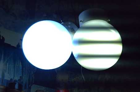 Two
LED lights hung up in the kitchen: on the right is the original. The
strobe effect so common with fluorescents, here interacting with the
camera to make dark stripes, is what I've since avoided by adding a
filter capacitor or using a 'modern' regulated power adapter. (I do
plan to add a filter capacitor to this one - running water in the sink
below looks weird.)
Two
LED lights hung up in the kitchen: on the right is the original. The
strobe effect so common with fluorescents, here interacting with the
camera to make dark stripes, is what I've since avoided by adding a
filter capacitor or using a 'modern' regulated power adapter. (I do
plan to add a filter capacitor to this one - running water in the sink
below looks weird.)
The left hand light is the new 1100 lumen "cold white" one. Tho I
reduced the exposure, the bluish color only shows at the top where it's
not quite so bright, and a bit in the dark strobe areas on the other
light.
LEDs
I got my big order from Deal Extreme and on the
16th(?)
put together a
two emitter light with the "20 watt, 1500 lumen, 15000K cold white"
emitters. These cost about 40% more than the Cree XM-LAWTs but give 50%
more light, using somewhat higher energy. They have an added attraction
of being 12 volts, so fixtures with any number of emitters (in
parallel) can be run from a 12 volt system. With the
usual deratings from the maximums to run cool and get or exceed "energy
star" spec performance, two emitters at 7 watts each should be giving
about 1100 lumens.
The 'cold white' light seemed bright and rather bluish,
but it's funny how the eyes adapt. After a while of that, all my 'cool
white' lights, that I think of as being relatively pure white, seemed
yellowish.
Still, 3 and 4 emitter fixtures
of this
type (~1700 and 2200 lumens, 24 and 32 watts) will need 3 amp power
adapters instead of about 1.5 amp, so it doesn't let me order only one
type of power adapter.
Of the several types I've
tried so far, these and the Cree "X-Lamps" seem the most suitable.
These
appear to be made the same as the 32 volt one I bought and used for the
shop light, but smaller.
I found a spool of #26 Ni-Chrome resistance wire at Queale
electronics to use instead of buying 5 watt resistors in packs of two.
I thought I could cut the pieces a bit long, test them, and add solder
along the
wire to effectively shorten them to suit. A second objective of using
resistance wire is to try and get a positive temperature coefficient of
resistance to counteract the strong negative change of forward junction
drop of the LEDs with temperature. I find I'm having to put in
considerably larger resistances than work well at room temperature, and
the lights get brighter and draw more current as they warm up. If the
resistances increased substantially with temperature, more of a steady
state brightness might be achieved.
To my chagrin however, I discovered that nichrome wire
can't be soldered. I guess the solder won't stick to the chrome. This
makes connecting the strong but fine wire difficult. I might just go
back to resistors.
Electric bills continue low
According to my electric bill, from mid October to mid
November I used 32 KWH of electricity per day, including a certain
amount of electric heat. Last year it was 49 KWH/day. It was 20-30$
less than I anticipated. Taking a median figure of 25$ and figuring the
darkest winter months are yet to come, and that there are no more bulbs
to replace, that's probably around 300$/year being saved by having
mainly LED lights instead of some incandescent (2/3 of them?) and some
compact fluorescent (which I found dim and didn't like the light of).
My investment in various parts and LED emitters for doing
the house lights myself (estimating the various lights without actually
adding up all the bills) was around 400$.
I don't leave every light on, but I do have a large house
and I don't flip them on and off as I go from room to room, either. The
kitchen lights (now around 25W) are often on, and either the machine
shop, the livingroom or my office lights, or maybe two of them, will be
on depending what I've been doing. The lights in the dark hallways (now
8W and 5W) are usually on.
Replacing at least lights that are turned on a lot with
LEDs is a good investment!
Energy Star
After a couple of weeks I finally looked into getting
Energy Star approval for the LED light fixtures. Then their PDF
application form on the web wouldn't open properly. I e-mailed and
eventually got sent another copy of the same unusable form.
Several days went by between each response from Energy
Star. Selling LED light fixtures had promise, but the cost seems too
high without the Energy Star approval and consequent BC Hydro rebate to
purchasers.
I finally asked for a copy on paper in the mail. While
waiting for a reply to that request, I thought to send a friend the
file and have them try. It worked fine for them, and they sent me back
a copy re-saved using an older PDF program. This worked fine. By then
it was the end of the month.
I should have been
onto the application
earlier, but I wanted to have at least "pre production" fixtures made
and be sure what I was doing first. I didn't expect it to take weeks
just to get the forms.
Nickel - Metal hydride Battery Project
Ultimate Battery Stick?
 As I
considered mounting the batteries in the Sprint, I thought it
would be good to enclose them in one big housing so there weren't a
bunch of little pipes with live ends sticking out. But that would be
putting batteries in
cases into a case.
As I
considered mounting the batteries in the Sprint, I thought it
would be good to enclose them in one big housing so there weren't a
bunch of little pipes with live ends sticking out. But that would be
putting batteries in
cases into a case.
Then I thought of making making long thin square ABS
plastic boxes to
enclose 4 or 8 strings of ten cells, with the contacts on the inside
except for two terminal posts.
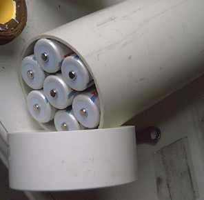
Then I thought of using a bigger pipe. A quick mental
calculation suggested seven strings might fit nicely into a 4" I.D.
pipe. I tried it out, and this proved true.
At 6.50$ per cell, the cost of each pipe works out to
about 475$ (my cost). I preferred last July's sale price of 5$ - they'd
be under 400$. (Perhaps I could make and sell the pipes as cases, and
let other people buy their own D cells to fill them.)
With a strut or two to prevent the strings from
twisting, one end with a flat metal plate, and one end with seven bolts
that could be adjusted for contacts, a 70 amp-hour, 6 or 12 volt
battery stick
should be easily made. The 12 volt one would weigh about 30 pounds.
Three 12 volters should put out plenty of current to run an Electric
Hubcap motor, and would fit nicely in the Sprint radiator area.
4" diameter pipe holds the batteries of 7 small pipes:
70 D cells for 70 amp-hours at 12 volts.
The 2.52 KWH should be
good enough for testing and short trips - plenty of amps. But it won't
give a car
(even a Sprint) a lot of range, so I'll doubtless want to expand on
that once it's on the road. Doubling it would be great, but owing to
the cost, I might just add a single string or two at a time. Or maybe
there's a good pipe size for
70 x AA cell (17.5 AH/210 WH) pipes?
Come to think of it, the offer to borrow 3 KWH @ 36 volts
of lithium ion batteries is doubtless still good. They might fit in
under the hood somewhere, with a battery switch to select between them
and the NiMHs.
Lead-acid EV battery options
Other than that, I might put in some lead-acids, with a
battery switch
to select NiMH, or PbPb if the NiMHs run out of juice. Lead-acids with
sodium sulfate should last quite a while if they're only occasionally
used, essentially as backup batteries. It looks like there'll still be
room for 3 under the hood. Of course, even three 100 amp-hour units
would be 135-150 pounds - plus 3 more (PbPb) chargers. That's like
lugging around an extra passenger, but valuable when needed. And having
to switch gives warning that you're hitting the range limit and need to
recharge soon.
Of course, you won't
actually get anything like 100 amp-hours out of them. Derating for
PbPb, and at the higher discharge rates of electric driving, suggests
about 25 to 30. (How "cheap" is lead-acid when everything's taken into
account?)
Arbitrarily continuing this somewhat off-topic train of
thought, if one were
to use lead-acid more, or entirely, two banks in parallel would drop
the currents in half and each bank would be more productive, perhaps 30
to 35 amp-hours for a total of 60 to 70, thus 270 to 300 pounds
yielding similarly to the 70 AH (probably should derate the NiMHs to 60
for high currents as well?) from
the 90 pounds of NiMH dry cells.
Six 6V golf cart
batteries should do
somewhat better than the six 100AH/12V cells, maybe 80 to 90 AH... but
they weigh and cost
proportionately more, 370 pounds and 960$. Three parallel banks of
100AH/12V (405-450 pounds) should
yield still better results (with the currents being divided by three),
35 to 40 AH each, 105 to 120 AH total... and also make the Sprint
heavier than it was with the gas engine system in it.
Two 70 AH banks of
NiMH D cell pipes would be at least as much available energy as that,
much longer lasting, and just 180 pounds - reminding
us why lead-acid isn't a very popular EV choice. They would also cost
3000$ instead of 1000$
- reminding us why the owners of big oil should
be relieved of their strangleholds over better economical battery types.
Yet another - and simpler - way to use lead-acids to get
sufficient batteries with less expense would be to use them in series
with NiMHs. Charging each 12 volt
section independently allows this.
One would want the lead-acids to have at least as many effective
amp-hours as the NiMHs if they are to last at all. One could put in
(eg) two NiMH "Super Battery Sticks" of 70 amp-hours for 24 volts, then
finish with two 100 amp-hour lead-acids in parallel for the third 12
volts, making 36V, 70 AH and 150-160 pounds. Or if three NiMH
supersticks were used initially as I'm planning, one could later add
one more (paralleling two pairs for 24 volts) and use four lead-acids
in the last position to get double the above energy and almost double
the range.
Still better of course would be to get my own economical
chemistry batteries working to the point where I could use them in the
car.
Turquoise Battery Project
Making Zinc Powder
 I was sure
using some zinc metal powder rather than just
starting with yellowish zinc oxide would make a better electrode. I
can't seem to
find it in town. I can't think who might have it. I tried ordering some
on the 6th, but the e-bay seller wasn't sure he could ship it outside
the USA. I e-mailed two potential Canadian sources but got no replies.
Sigh!
I was sure
using some zinc metal powder rather than just
starting with yellowish zinc oxide would make a better electrode. I
can't seem to
find it in town. I can't think who might have it. I tried ordering some
on the 6th, but the e-bay seller wasn't sure he could ship it outside
the USA. I e-mailed two potential Canadian sources but got no replies.
Sigh!
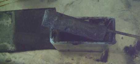
I tried grinding some from a zinc rod I had. It was very
slow going. At one point (foto) I made a block to hold the zinc rod,
but held like that it quickly got too hot. By the 10th (after
several 10-15 minute grinding sessions) I eventually decided I had
enough
powder/flakes for an electrode, but it was more flakes than powder -
the powder would build up on the grinding wheel and then flake off.
Doubtless the particles comprising the flakes were all fused - melted -
together.
I was dubious about using it.
Zinc from zinc oxide
 Then I got the idea to try and reduce some zinc oxide to zinc powder
electrically. I got a round "basket" of perforated brass sheet from an
older experiment.
Then I got the idea to try and reduce some zinc oxide to zinc powder
electrically. I got a round "basket" of perforated brass sheet from an
older experiment.
But wouldn't it just electroplate the brass with zinc? I
mixed 60g ZnO and 25g graphite powder to keep the zinc from
conglomerating into a solid piece or plating. About half of it tamped
into the basket.
Knowing salt electrolyte would corrode the basket, I used
potassium hydroxide for the electrolyte, and I used a piece of graphite
sheet for the positrode.
I attached a power adapter and got 2.3 volts with a
current of .27 amps. Since there was no real positive electrode to
oxidize, the oxygen from the zinc oxide should bubble up from the
graphite sheet. Soon it was in fact bubbling merrily with small, rapid
bubbles.
If I had used a nickel or grafpoxy plated positive
electrode with nickel hydroxide, I'd have made a nickel-zinc alkaline
battery. Many have tried to get good cycle life out of such a cell. I
only needed it to charge once.
Unfortunately, I left it a few minutes, and when I came
back, the substance in the basket had frothed up and spilled all over.
Of course! - 2.3 volts was too high and the zinc filled negatrode would
be generating hydrogen. The trapped gas puffed up my nicely compacted
basket of zinc/graphite. I limited the current to reduce the voltage to
about 1.5 or less, but by then it was a mess in a tub
of caustic hydroxide. It did however seem to be charging.
I read over means of making zinc electrodes in Alkaline
Storage Batteries by Falk and Salkind. I noted that they were
usually immersed in a tank of electrolyte, left to sit for a day, and
then charged against a 'dummy' positive electrode, and maybe run 3
charge-discharge cycles. Soluble impurities would leach out of them.
Then they were dried. It occurred to me that even if I was making salty
batteries, I could use the same procedure. The mobility of zinc ions
when cycling in alkaline solution should be an advantage for a few
cycles, forming conductive zinc pathways within the electrode to
improve the current capacity.
I also noted that zinc electrodes were said to be very
fragile before
'forming' with initial charges and discharges - exactly as I had
discovered. Another possible means of making them was by sintering zinc
oxide at
around 750ºc for 20-80 minutes (I presume with a collector screen
enclosed). Those would be more solid, but might be less amp-hours by
weight. Seemingly, it would be an easy thing to try out - simple
ingredients! But for use in salty electrolyte, the collector screen
needs to be grafpoxy coated. That would burn up at 750º. Not so
simple after all! Zinc metal powder sinters at kitchen oven
temperatures (over 200ºc), as I had found doing the 'ersatz powder
coating'. That might make nice pre-charged electrodes, but it's still
too hot for the grafpoxy.
Another thing mentioned was 1-4% mercury oxide to raise
the hydrogen overvoltage. No thanks. I'll stick with the
environmentally friendly antimony oxide, and maybe the eggwhite, maybe
a rare earth.
Anyway, it should be less prone to hydrogen generation in salt solution
- after all, standard dry cells stay charged for years with nothing but
zinc sheet metal... unless that's actually an alloy with some small
additive for overvoltage.
On the 27th I took the remaining zinc oxide and graphite
and tried again, adding a bit of antimony oxide to the mix. This time I
limited the current, and the voltage started a slow rise from 1/2 a
volt. On a whim I replaced the graphite "+" with a flat nickel
pocket electrode from a nickel-iron pocket cell. A Ni-Zn alkaline cell
should charge
up to about 1.75 volts, without the oxygen bubbles unless the nickel
became completely charged. In fact, after 3 hours or so the zinc was
making dirty hydrogen bubbles with the cell at 1.72 volts. The zinc
couldn't
possibly all be charged so soon. Of course!, I had just tamped it into
the basket: it wasn't properly compacted, so resistances away from the
basket metal were bound to be high, allowing some zinc to charge
fully without getting to the rest.
I tried shorting the cell, twice. It put out just over an
amp, which quickly dropped off. Not bad, considering the poor interface
between electrodes, and all the work I go to to get an amp out of a
salty cell! No wonder everyone went to
alkaline cells and abandoned the the harder job of trying to make
rechargeable salty cells.
I decreased the
current to eliminate the bubbling, and went over things from the
battery book... oh ya,
'immersed and left to sit for a day'. I removed the charge.
Even 2 or 3 hours later, when the voltage had dropped to
1.1 volts, it still put out over half an amp when shorted.
Another item to consider
was that afterwards I'd have to dig the mix out of the basket and
properly compact it into the desired electrode form. Why wouldn't I
make the desired electrode first, then 'form' and charge it in the
alkaline solution, and then simply rinse it and use it in the salty
battery? The zinc should migrate to form great dendrite 'tentacle'
connections during forming in the alkali, and they'd become fixed in
place in the salt battery with every prospect for a super long life,
highly conductive electrode. I could make some sort of little basket or
compartment so the electrode could be inserted and removed with little
stress.
All this seemed very good. But I was still wondering why I
couldn't seem to buy something so simple as zinc powder. However, I did
a bit more research, and found that something I was doing was making it
into better oxide than it started as. Not what I thought, tho...
Best Zinc Electrode!
Back to the basics... it seems that not only zinc powder,
but zinc
oxide powder will absorb carbon dioxide from the air and form zinc
carbonate. Zinc carbonate is passive in the battery. Perhaps this is
partly why results from my first zinc powder electrode didn't seem so
great? One can heat zinc carbonate to produce "calcined" zinc oxide and
CO2, but it seems that for batteries there's a better way.
Simply putting zinc carbonate into alkaline solution
causes it to become fine, high surface area zinc oxide. This is
sometimes
termed 'active' zinc oxide. 'Fluffy' high surface area chemical is
ideal for
batteries, yielding the closest to the theoretical amp-hours of the
substance.
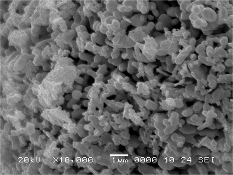
"Active" high surface area zinc oxide
(ZnOxide.org)
So all I have to do to get an ideal zinc battery electrode
is to make the electrode, immerse it in potassium hydroxide solution
for a while (like the alkaline battery makers), then rinse it
off - probably no electrolyzing or anything. And then - presumably - no
dendrites in salt solution to deteriorate the electrode and limit the
battery's cycle life. It appears I've stumbled onto the best form of
zinc negatrodes!
It looks like the only thing that might be a better
electrode is if
the hydrogen overvoltage with manganese can be raised that extra .3
volts so that a manganese negatrode works properly. The eggwhite didn't
seem to do it. I think that's worth more research, but I'll go with the
zinc because it's well known to work well as is.
http://www.TurquoiseEnergy.com
Victoria BC