ma
Turquoise
Energy Ltd. News #47
Victoria BC
Copyright 2011 Craig Carmichael - January 2nd 2012
http://www.TurquoiseEnergy.com
= http://www.ElectricHubcap.com
= http://www.ElectricWeel.com
Four Years of Electric Transportation &
Energy Projects
Month In Brief (Summaries)
Electric Hubcap System
* in the news: A new type of turbine engine, by Robert Mueller at
Michigan State U.
* in the news: Replica of first functional hybrid car, from 1900
Magnetic Impulse Torque Converter Project
* Construction of converter, 10" diameter with springy arms - worked
well at low RPMs only.
* Plan for next version
* Initial tests: the potential is there... how much copper and how many
magnets will it take?
* Theory of Operation
Electric
Weel Motor - no report
Sprint
Car Conversion Project - no
report (see Torque Converter project)
Prospective Electric Outboard Motor from Scratch Project
* Chain drive electric outboard concepts
* Collecting parts
LED Lighting Project
* Wall mounted fixtures: easy as hanging a picture!
NiMH Battery Project
* Second Hand Tip: Vaseline on contacts prevents corrosion, improves
contact.
* First Super Battery Stick made
Turquoise Battery Project
* Of interest: Nickel-Zinc/alkaline 1.6 volt batteries are available
(PowerGenix.com)
but only AA size.
* Zinc electrodes
* New electrode compactors
* Stibnite for manganese negatrodes
Newsletters
Index/Highlights: http://www.TurquoiseEnergy.com/news/index.html
Construction Manuals and information:
-
Electric Hubcap Motor - Turquoise Motor
Controller - 36 Volt Electric
Fan-Heater
- Nanocrystalline glass to enhance Solar
Cell performance - Ersatz 'powder coating' home process for
protecting/painting metal
Products Catalog:
- Electric Hubcap Motor Kit
- Sodium Sulfate battery longevity/renewal
- NiMH Handy Battery Sticks, Dry Cells
- LED Lighting Products
Motor Building
Workshops
...all at: http://www.TurquoiseEnergy.com/
(orders: e-mail craig@saers.com)
Four Years of Electric Transportation & Energy Projects
If I had understood
when I started that the idea for turning cars into hybrids might take
half a decade to develop, there's an excellent chance I'd never have
started. However, I did start, and seeing great value in the idea and
progress over time, I've continued. There has also been personal value,
learning
and growth in the process. I haven't made any money so far and live
rather "on
the edge", but things more important than money - "treasures in Heaven"
- have been earned, and
the fruits of the projects are starting to ripen.
I'm sure that, having published all the "how to" (&
"how not to") details
for everyone, my inventive work (especially insofar as it's successful)
will gradually spread and help break the impasse of vested interests
and their dinosaur technologies that have been holding back progress to
a better, kinder age. And when governments finally wake up to the value
of creating their Department of Progress to administer
inventive projects, patents and new ideas on some sort of organized
basis rather than allowing chaos to reign, peaceful progress towards a
utopian society will be powerfully assisted.
Finding no support for the ocean wave power project, I
started January 2008 thinking of just two new projects, ones that
wouldn't succumb to the indifference or hostility of those with
resources: a
supermagnet 'pancake' motor and a solid state motor controller for that
motor, to be
installed into a car. That certainly seemed like a sufficient
challenge! The objective: a simple, economical,
and ultra-efficient
add-on electric drive system to turn typical cars into plug-in hybrids,
that would "catch on", probably with DIYers at first, and eventually
come to dominate the market and move society rapidly away from rampant
petroleum consumption.
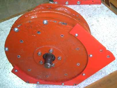
L: Stator of first good "Electric Hubcap" motor - 9 coils on a disk
brake rotor mounting plate,
fall 2008
R: Latest composite material motor (steel bracket mounting is for
Sprint car installation)
The motors have progressed in stages from a vague idea
to an excellent, super efficient (~95%), "on wheel" add-on motor, the Electric
Hubcap, to turn any car into a plug-in hybrid. They're easier to
make at home than other motors and boast several contributions to the
motor making arts. As far as I can find, these must be about the best
motors in the world, tho certainly a few rough details could be
improved. (Kit
499$ magnets not included; Motor making Workshop (leave with your own
motor)
800$. That's as cheap as I can do it.)
The solid state BLDC motor controllers went through
a number of design revisions and eventually arrived at an advanced,
compact,
reliable and robust, Direct Torque Control, simple and easily repaired
unit. The aluminum chassis is also the enclosed wiring junction box for
the system. It's just about now
ready for 'beta testing' and then the marketplace. Special feature: no
microcontroller or programming, just hardwired circuits. (499$ complete)
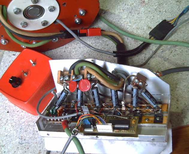
Turquoise Motor Controller in partly disassembled chassis.
(This chassis was cut down to fit a motorbike.)
The same January that I first started, a search for
batteries
disclosed that good alkaline batteries for electric travel such as NiMH
and NiFe apparently had been
deliberately removed from the market and suppressed. It turns out that
somewhat more economical, high energy nickel-zinc NiZn should also have
been available by 2008, but they're only available as AA cells at a
higher price than NiMH. (See NiMH Project article below.) Only
lead-acid and
the priciest
lithium types were available. This put my nose out of joint, and I
started considering how NiMH batteries might
be made at home. I added this third project to my list.
But I soon figured still better batteries must be
possible. I
called it the Turquoise Battery Project, not to get too
specific, since I was trying out
various potential chemistries. Learning as I went, I
eventually found some
workable higher energy chemical reactions, and came up with some
new construction ideas, which turned out to be more important and
tricky than the actual electrochemistry. Details are scattered through
my
newsletters. Although I haven't yet made a practical battery,
important hurdles have been leapt and a practical prototype doesn't
seem to be too far
off.
Compacting tool makes powders into battery electrode "briquettes"; a
salt electrolyte test battery with 'grafpoxy' coated current collector
grills
Motor/car testing proved that practical direct drive to a
car wheel would require a very
oversized and heavy motor. For a light wheel motor, "gearing down"
would be necessary. An efficient torque converter seemed to be the best
way if not the only
way my small wheel mount motor could put a car on the streets.
So in the spring of 2009 the
Magnetic or Mechanical Torque Converter project was forced on me
in order to achieve the main objective.
Amazingly, since the 1926 gas sipping, two cylinder Constantinesco
car and railway locomotives until now, no one had made another
successful mechanical torque
converter for motor vehicles.
I had little idea where to start. Many wildly different
directions were possible, both mechanical and magnetic. I had no means
to reliably measure the torque, and I went through
a succession of failed designs
and trials. I finally came up with the idea of a torque converter followed
by a gear speed reduction, eg 2, 3, or 4 to 1. No doubt
Constantinesco's units had even more substantial reduction at the rear
axle, a point I think later attempts including mine overlooked. This
would divide the foot-pounds
the converter would have to produce by the ratio, still without
creating the super-high RPMs on the highway that a single fixed gear
ratio ends up having.
Then with a November 2011 "Eureka!", I came up with a
magnetic impulse torque converter design that applied all I'd
learned in the best way. I was sure it would
really move a car, and in
December I built it. The first version didn't move a car, but the
principle is sound. Bench tests just before year end with a single,
longer wedge of copper (and finally with a means of
measuring output torque; see article below) had more torque, and it
appears that torque to move
cars just needs sufficient supermagnets and copper wedge area for
sufficient force coupling, perhaps in two or more interleaved layers.
The idea and
principle is so simple and obvious in retrospect
that anyone might say, "Aw, he just drew that on a napkin over coffee
one day!" People would feel that any wealth attained from it was
unearned (and the
present patent system ensures there's under 1% chance of an inventor
making money),
discounting the far-reaching value of the idea, the 2-1/2 years it took
me to come up with it, a lifetime
of mostly uncompensated inventive work, and the fact that in spite of
various efforts by many people, no one else had done it.
 In the
meantime, just to show my Electric Hubcap motor worked, in
summer
and fall 2010 I converted a Honda 7.5 HP outboard to an Electric Hubcap
motor, reworking the original motor #2 from 2008 that had moved the
car.
Videos of the boat running are on YouTube. I now have ideas for a
better, "from scratch" chain drive outboard, using plastic pipes for
the main body parts. (article below)
In the
meantime, just to show my Electric Hubcap motor worked, in
summer
and fall 2010 I converted a Honda 7.5 HP outboard to an Electric Hubcap
motor, reworking the original motor #2 from 2008 that had moved the
car.
Videos of the boat running are on YouTube. I now have ideas for a
better, "from scratch" chain drive outboard, using plastic pipes for
the main body parts. (article below)
And Tristan Money took my Motor Making Workshop and built
one of the motors at about the same time. It went onto an off-road
motorcycle, but the 4 to 1 chain gear ratio (to my surprise) proved
inadequate. It finally ran up a slight slope instead of only down by
putting 80 amps into the motor, but it was like trying to
start a car moving in third gear. The torque converter should be the
answer for this vehicle as well.
I delved into other things along the way.
 I conceived of
a pancake motor that would have the high
torque and low
RPM needed to drive car wheels directly without being ridiculously
heavy and overpowerful as well. The key to torque is forces around a
large
diameter rim - the interior of the motor is largely empty. This motor
was partly insurance in case the dragging torque converter project
never panned out. The 15 KW Electric Weel would simply be the
coils and magnets of three 5 KW Electric Hubcap
motors spread around a 26" rotor and rim, having 9 times the torque,
1/3 the RPM, and still being just 5" thick. I plan to finish it in
2012.
I conceived of
a pancake motor that would have the high
torque and low
RPM needed to drive car wheels directly without being ridiculously
heavy and overpowerful as well. The key to torque is forces around a
large
diameter rim - the interior of the motor is largely empty. This motor
was partly insurance in case the dragging torque converter project
never panned out. The 15 KW Electric Weel would simply be the
coils and magnets of three 5 KW Electric Hubcap
motors spread around a 26" rotor and rim, having 9 times the torque,
1/3 the RPM, and still being just 5" thick. I plan to finish it in
2012.
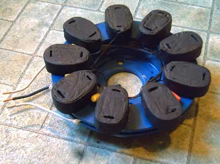
Nanocrystalline material
seemed to promise better motor coil cores (especially better than my
workable but crude nail gun finishing nail strip iron laminates), and
ceramics was promising and the least explored area in this field. Later
I found excellent low-loss iron powder toroid cores that were doubtless
better
than
anything I could have made even if I'd attained a successful result.
(27 of them are seen here in the Weel motor coils.)
But in the attempt, I came up with two things. One was a
'magnetically conductive' ilmenite-sodium silicate skin for coils that
did significantly improve motor performance.
The other was a
great
nanocrystalline titanium dioxide, borosilicate glaze formula that could
be of service for superior solar collector glass. I developed some
other ideas for better dye sensitized solar cells (DSSCs) as I worked
on the glaze mix and technique. So far I haven't done anything useful
with it except create the
glaze. But only this month did I finally find some iodine/potassium
iodide solution, the required electrolyte for DSSC cells.
Sometime, I found out that lead-acid batteries could be
renewed by replacing the acid with sodium sulfate in distilled water,
and further, that they could be given long initial life - 3 or 4 times
as long - by adding the sulfate salt, and further, that battery makers
have known all about it since before world war two. They don't put it
in regular batteries because (a) short life batteries are a good scam,
and (b) because they'd then be too practical and would make economical
electric vehicles practical.
That led me into a side venture to determine and publish the best ways
to do
it and to figure out what was going on.
I made a 36 volt electric heater for electric cars. (I
finally found some good looking ones on line, but only after I'd
finished making mine.)
I started making a small pulsejet, a type of jet engine
with no moving parts, but I got
sidetracked and haven't finished it so far. Pulsejets spit out pulses
of flame like a cutting torch,
and I thought I could make one to cut steel plate with. But about then
I finally found
two abrasive waterjet companies (a service I had been looking for since
the start).
They do nice, clean, exact cuts and were pretty affordable, which
solved the immediate needs for cutting out steel rotors and parts for
the motors.
About the end of 2010 it seemed nickel-metal hydride D
cells had dropped in
price since early 2008 from 10$ to about 6$. This seemed to make them
more
viable for electric transport. Until and unless I got my own batteries
working and practical, NiMH
dry cells seemed like the most workable EV material.
 The currents
listed for the cells and the
great results I was getting with some new NiMH AA cells in January 2011
seemed also to
indicate that NiMHs might be used as car starting batteries for gas
cars. I bought some and found they did indeed start the car. The car
13.8 volt standard charging system turned out to be the ideal constant
charge voltage for (10x) NiMHs, and the cycle life given seemed to
indicate they should surely last for at least a decade if not two or
three as
a
car battery. It apparently hadn't been done before -- the manufacturer
had no idea how long they might last. At the start of 2011 it was just
a theoretical possibility, but since I first tried it in February my
car has been lead battery (-30 pounds) free. 4 different battery
designs
have been tried: with 60 "4/3 A" cells, 120 AA cells (9 pounds), 30 D
cells (most 'oomf', 12 pounds) soldered into a pack, and finally 30 D
cells in
6 - 6V "handy battery stick" pipes. NiMH are proving to be much better
car batteries than lead-acid, saving gas by lighter weight and lower
idle speed, and leaving the lights on for a few hours a couple of times
has had no noticeable detrimental effect.
The currents
listed for the cells and the
great results I was getting with some new NiMH AA cells in January 2011
seemed also to
indicate that NiMHs might be used as car starting batteries for gas
cars. I bought some and found they did indeed start the car. The car
13.8 volt standard charging system turned out to be the ideal constant
charge voltage for (10x) NiMHs, and the cycle life given seemed to
indicate they should surely last for at least a decade if not two or
three as
a
car battery. It apparently hadn't been done before -- the manufacturer
had no idea how long they might last. At the start of 2011 it was just
a theoretical possibility, but since I first tried it in February my
car has been lead battery (-30 pounds) free. 4 different battery
designs
have been tried: with 60 "4/3 A" cells, 120 AA cells (9 pounds), 30 D
cells (most 'oomf', 12 pounds) soldered into a pack, and finally 30 D
cells in
6 - 6V "handy battery stick" pipes. NiMH are proving to be much better
car batteries than lead-acid, saving gas by lighter weight and lower
idle speed, and leaving the lights on for a few hours a couple of times
has had no noticeable detrimental effect.
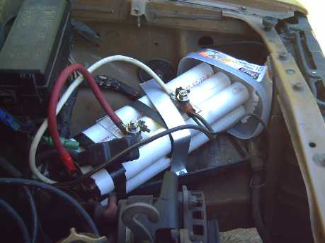
New this month:
Ventilated NiMH Super Battery Stick
70 D cells: 70 AH, 12 V, 4.5" x 25", just 28 pounds
I found out later that NiMH D cells are popular for hybrid
car batteries, since larger NiMHs are suppressed. Developing them to
make
them good enough for that use, and developing AA cells for the ultimate
possible energy density for small devices, explains their amazing specs.
 In spring
2011, I ordered some LED emitters to try out LED
lighting. I discovered they really did make a lot of light with very
little
electricity. But one could spend 50$ at Canadian Tire and get just a
450 lumen screw-in 'bulb', barely replacing a 40 watt tungsten
lightbulb. There were also LED light fixtures... with no diffusers,
just glaring little points of intense light. I progressed to making
700, 1050 and 1400 lumen lamps and 6" globe light fixtures that run off
power adapters, and realized they were better than what could be
purchased. I converted my whole house and started saving 20-30$/month
off my electric bills.
In spring
2011, I ordered some LED emitters to try out LED
lighting. I discovered they really did make a lot of light with very
little
electricity. But one could spend 50$ at Canadian Tire and get just a
450 lumen screw-in 'bulb', barely replacing a 40 watt tungsten
lightbulb. There were also LED light fixtures... with no diffusers,
just glaring little points of intense light. I progressed to making
700, 1050 and 1400 lumen lamps and 6" globe light fixtures that run off
power adapters, and realized they were better than what could be
purchased. I converted my whole house and started saving 20-30$/month
off my electric bills.
When BC Hydro started offering rebates on qualified LED
lights - and the available crap qualified - I decided I should make and
sell my superior fixtures - the rebates would make them more
affordable. Over the rest of the year I refined the
design and
worked on getting the requisite "Energy Star" approvals. I've settled
on promoting 15 watt, cold white, 1100 lumen fixtures and maybe 15
watt,
1400 lumen cool white ones (costs about 15$ more). In fact, converting
to these efficient LED lights from incandescent will pay off even the
full price in electricity savings within two years for lights that are
turned on much of the time, and the "cool white" is about the whitest
artificial lighting available. "Cold white" is a bit bluish. Both are
much nicer light than fluorescent, and IMHO nicer than incandescent.
I enter 2012 with the torque converter seemingly nearly
ready to give me an ultra efficient electric car to
hit the streets with, economical high energy batteries hopefully about
ready
to work, a plan for a better DIY electric outboard motor, and
merchandise
ready or about ready to go: motor kits, BLDC motor controllers, NiMH
Handy Battery
Sticks,
and LED
light fixtures.
Not that I've sold anything to speak of so far. Selling
seems to be a different talent than mine.
December in Brief
On the second I had
what seemed like a better and also simpler plan for the magnetic
impulse torque converter: just springy arms would replace the entire
springing mechanism. It looked like a workable converter was just a few
steps away. I started in on the output side, now just a hub holding a
couple of arms with copper blocks on the ends. The rectangular steel
hub block was
fitted on the shaft that day, and the output section was ready on the
6th. I finished it and tried it on the bench and in the car on the 7th.
It seemed great on the bench, but in the car it only had
about 1/4 of the force needed to move the car even on level ground.
Everything worked great up to about 150 RPM, the output torque pulses
'unstoppably' shoving my hand an inch or so at power levels where the
motor rotor (same diameter) can
readily be held stopped. But above that the force didn't seem to
increase with the speed, and even seemed to drop off at high speed.
Evidently non-linearity of force with speed that I'd foreseen as a
potential but (I thought) unlikely problem does occur. In
the days that followed, I tried modifying the force elements. An air
core coil in place of the copper block didn't fare well. Annealing the
copper blocks (5% more conductive) seemed to help some.
Next: A single long wedge/arc of copper, eg 6", with one
magnet set, allows the motor 4/5 of a rev to speed up, then slow
it down more, transferring the maximum force from the input to the
output within that 6" period, which I hope will also prevent
over-revving to
speeds where it ceases working well. I took the electromagnetic
components apart to start over, as I felt such a long wedge of copper
would have to be on the rotor side, with the magnets on the springy arm
- opposite to how I'd done it. On the 30th this did in fact produce
about double the torque with only two magnets. It appears that four or
five magnets
should produce torque values that (with the gear reduction following)
might
push the Sprint car across the bumpy lawn.
On the 13th I got a chest cold. It came out of the blue
within hours of eating a cookie unexpectedly "laced" with two big,
chewy, hidden candied fruits, after playing in a concert. I'm convinced
that candied fruit is the single handed cause of 3/4
of holiday season colds and flus and I try to avoid them.
On the 14th, I decided it was time to quit the machine
shop for a bit and get back to the Turquoise battery project. And I
started working on the battery making manual to eventually put up on
the web.
Noting pinholes in the grafpoxy, I put a second coat on
some grills, which clogged many of the mesh openings, Then
I thought of diluting the epoxy next time to make a thinner coat that
would hopefully cover better. It also appeared I could probably make
sheets of conductive grafpoxy plastic. They might be useful as a common
conductive wall between two cells, so glued-together cells could form a
lighter higher voltage battery. Finer mesh grills would also be
valuable.
Then, having decided to go with small format electrodes
for good, after making a (poorly conceived) "new" compactor for small
electrodes from part of the original one, I did a zinc electrode. Later
I did a better small compactor from the newer large one. The 31 grams
of zinc oxide should theoretically make about 20 amp-hours. The
internal space in my cells is about the same as a D cell, 40cc. Working
it out revealed only around 10 AH of nickel electrode could be fit in.
Oh well, it has a higher voltage than a NiMH D cell.
By the end of the month, I had put a couple of dozen hours
into the battery making manual and it was taking form. The grafpoxy
coated grill electrodes in the new cell seemed to be lasting well, but
the cell itself hardly worked - I tried to re-use a nickel
electrode that had expanded and it had little to no conductivity.
Christmas intervened and I didn't get another electrode or cell made.
I did manage to get hold of some antimony sulfide
(couldn't find any last time I tried) that I hope will raise the
hydrogen overvoltage enough to make a manganese negatrode work. If it
does, it'll be about the highest voltage and highest energy negatrode
ever, and probably very long life.
In Passing: more dirty tricks of the rich
I was hoping to have a month pass with nothing to talk
about but the energy projects, but on the 10th I overheard that some
very rich people - she mentioned Nelson
Skalbania, Peter Pocklington and Donald Trump - "declare
bankruptcy as part of their business plan". By declaring bankruptcy
they avoid
paying income tax, and they can write off all their debts and losses.
They put their assets in trusts, in friends' names, in offshore
accounts, and wherever, so that on paper it appears they don't own
anything.
On the web I read
that Pocklington was arrested in California in 2009 on bankruptcy
fraud, claiming 20000000$ in debts and just 3000$ in assets, but he was
sentenced to just 6 months home detention. (What, he even got to keep
his home?!?!) This info seemed worth spreading. Skalbania may have had
more genuine financial troubles... or was he just better at the game
than Pocklington? I didn't look up Trump.
It seems inevitable that many people must have lost
investment money somewhere, somehow in this, and that these people have
acquired (or spent) it. How many rich people get there by using the
letter of the law to defy the intent of the law, cheating
people and the society that nurtured them as they go? It will give
them no peace.
Oh no, more... I've also heard that the John Deere tractor
company had gone out of its way in the 1920s to buy up all the draft
horses they could get their hands on... and send them off to glue
factories. Shortage of horses
of course forced the largest number of farmers to
buy tractors. Apparently there's no limit to immoral conspiracies and
scams if profits are to be made!
Electric Hubcap Motor System
New Gas Engine
I was sent a link to a news article about a new type of
engine that uses far less fuel and is small and light. Among many
possibilities, this would be great for a small "generator module" to
recharge car batteries while driving, preventing an electric car from
running out of range on long trips. Doubtless it could run on a number
of fuels such as methane (natural gas) or propane as well as gasoline.
http://news.discovery.com/autos/new-car-engine-sends-shockwaves-through-auto-industry-110405.html
I hope they don't fall unsuspectingly into the usual trap
of patenting it. Then
"the 1%" will acquire the patent one way or another and won't let
anybody produce them. You would think that when development of an
invention is funded with public money, either there should be no patent
granted, or the patent should be held by the government and royalties
collected on a non-exclusive license basis. Alas, a private patent that
can easily be bought to kill the new technology is a common condition
for applying for government funding as well as private. No wonder we're
still stuck with "big oil"!
From the article:
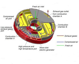 "Researchers at Michigan State University
have built a prototype gasoline engine that requires no transmission,
crankshaft, pistons, valves, fuel compression, cooling systems or
fluids. Their so-called Wave Disk Generator could greatly improve the
efficiency of gas-electric hybrid automobiles and potentially decrease
auto emissions up to 90 percent when compared with conventional
combustion engines.
"Researchers at Michigan State University
have built a prototype gasoline engine that requires no transmission,
crankshaft, pistons, valves, fuel compression, cooling systems or
fluids. Their so-called Wave Disk Generator could greatly improve the
efficiency of gas-electric hybrid automobiles and potentially decrease
auto emissions up to 90 percent when compared with conventional
combustion engines.
"The engine has a rotor that's equipped with wave-like channels that
trap and mix oxygen and fuel as the rotor spins. These central inlets
are blocked off, building pressure within the chamber, causing a shock
wave that ignites the compressed air and fuel to transmit energy.
"The Wave Disk Generator uses 60 percent of its fuel for propulsion;
standard car engines use just 15 percent. As a result, the generator is
3.5 times more fuel efficient than typical combustion engines.
"Researchers estimate the new model could shave almost 1,000 pounds
off a car's weight currently taken up by conventional engine systems."
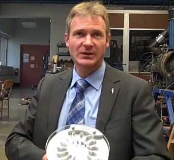
Norbert Mueller holding his prototype. The foto doesn't look like the
drawing, but details are scanty.
According to Mueller's web page at MSU, he works with
'turbomachinery', 'centrifugal compressors', 'wave rotors'
and several related areas, that would seem to make him a natural to
invent such a new machine.
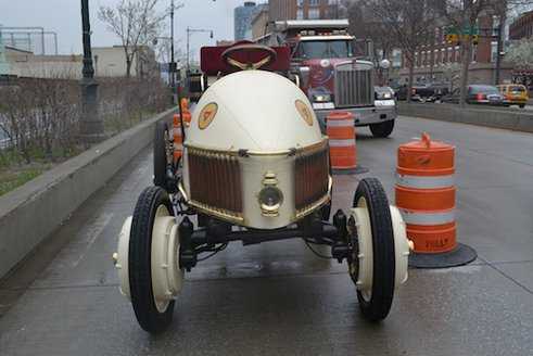
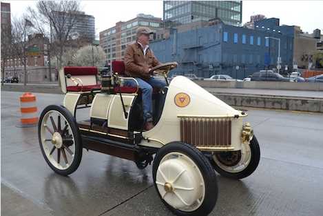
Replica of Porsche Hybrid from 1900
How long have hybrid cars been around? Evidently this one,
recreated by an unnamed hobbyist, was the first functional one, in
1900. It appears the two 2.5 HP gasoline engines are behind the front
seat. They charged batteries and powered the electric hub motors in the
front wheels. A single ratio gear in each hub was probably all that was
needed for the speeds you'd want to go on the rough roads of 1900:
faster than a horse or a bicycle - cool!
The turbine engine above would have left more room for
luggage and used less fuel. Great batteries would have let it go over
100 miles without any engine. A magnetic impulse torque converter would
have let it do 100 Km/Hr -- ooh, scary!
www.treehugger.com/cars/riding-the-worlds-first-hybrid-car-1900-porsche-semper-vivus.html
The outside profile of the front wheels isn't dissimilar
to what I hope to do with the Electric Hubcap system on rear wheels,
but evidently these motors and wheels weighed 200 pounds each, where
the Electric Hubcap system should weigh under 50.
Motor Controller
The IR2133-V2 circuit boards still didn't arrive. I
e-mailed to ask what's going on. Turned out I'd sent a wrong file and
they hadn't communicated that back to me. Hopefully it's on track now.
Magnetic Impulse Torque Converter Project
Construction
By Dec. 2nd, I'd figured out what I hoped was a better
plan for the converter. To implement the heavy springs, I would simply
mount the copper blocks on the ends of somewhat springy arms. There
would be no other mechanical moving parts, and in fact no output
"rotor" per se at all - just a hub on the shaft to hold the springy
arms, and the copper blocks on the ends of those.
The spring effect would be less dramatic, but it would
smooth the magnetic hits, which might be pretty abrupt with copper
blocks even tho nothing would physically touch, and still provide a bit
of boost to the torque. The rotating magnets would still pull the arms
forward, against the spring pressure. That would put considerable
pressure on the shaft, more and more as the arms became under more
tension, and added to that, the forward inertia of the blocks as it was
arrested. At some point, the magnets would reach the front of the
copper blocks and let go. When they did, the arms would spring back,
the rebound inertia continuing to push on the shaft for a further short
distance.
There needed to be a hub to attach the arms to. Since the
arms would be straight(?) pieces of steel, it seemed reasonable to have
a square or rectangular hub instead of round, so they could simply bolt
along the edges. I found a bar of mild steel 2" x 4" x .75" in my
stock. That seemed a good size as-is.
I couldn't make a 2-1/8" hole for an SDS bushing in a 2"
wide piece even if I could somehow drill it, so it would have to go
directly on the shaft with a slot for the shaft key. To make a 1" hole
through the center for the shaft I would need a 1" drill bit. The pawn
shops having none, I had to buy it new for 35$ (Best price in town, at
Canadian Tire - ouch!) I reasoned I'd surely want to drill more 1"
shaft holes at some point, since that's my "standard" shaft size. I got
the hole drilled the same day, drilling up a bit at a time from 5/16"
with 9 drill bits. It'll suffice, but it wasn't quite straight - what's
with the drill press?.. It looks straight.
Making the slot for the key seemed a different prospect.
In November I'd found how to mill slots into the shafts, but the end
mill bit wasn't going to go inside a hole sideways. Neither was the zip
disk on the angle grinder. This seemed to leave the dismal prospect of
filing it out. Or perhaps it could be chiseled/gouged out with a
1/4x1/4" lathe tool? Finally I got down to it and it only took about an
hour, using the edges of a couple of files and the lathe tool to square
up the inside corners. Then I drilled and tapped a hole on the side and
put in a set screw. The square block was fit on the round shaft - one
job done.
Evidently no one sells spring steel in Victoria, so I
decided to try regular steel - a .125" x 1" steel strip. If this went
straight out from the center to the copper block, it would only have 2"
of spring length. That didn't seem like much. Then looking at the block
hub on the shaft, I thought of using 2 pieces of .125" x .75", one from
each
side of the hub, to each side of the copper. That would keep the copper
lined up parallel to the magnets at the desired gap much better, and
pretty much the only flex would be along the travel axis, the desired
direction. I could attach it 1" out from center on each side, and at
over 3" and just under 5", and bend a little bow in between for flex
length. I bought the steel and cut, drilled and mounted the arms on the
hub on the 4th.
Last detail of the output side construction was - how big
to make the copper blocks? I had bought a 3" x 6" block, but that
didn't mean 3" x 3" was the best size. The two magnets were 2" x 2". I
decided on 2" x 3", with the 2" along the arc of travel so that the arm
would try to follow the magnets for only a short period to attain the
maximum torque increase. But if that seemed light on the interaction, I
could turn them sideways
for a 3" run. If that still wasn't enough, 3 magnets N-S-N on the 3"
copper would surely move anything - if the motor could handle it. I cut
the copper blocks on the 3rd, actually before the arms, so I had all
the main bits to lay out on the bench to determine details. Owing to
the 3" length of the blocks, the copper stuck out an extra 1/2" beyond
the 10" rotor diameter. But there
was room.
To keep the steel arms, which are of course attracted to
magnets, at a bit of distance from the input rotor, I decided to use
spacers of aluminum, so the copper would stick out 3/8" from the steel.
With these 1/8" thick spacers, and two 1/8" steel pieces clamped over
the main arms at the hub, I realized that if they were all on the
inside, a natural gap would allow the arms to spring without having to
bend them, so I arranged it that way.
On the input side, the only real variable was how thick a
rotor to use: how much flywheel effect was desirable? I had a 1/4",
some
5/16", and a 3/8", all made to fit on an SDS bushing and all 10" in
diameter. Two magnets went at each end, 180º apart. Once they were
glued on, it would be hard to change it. But excess weight - if it
really mattered - would work against the brakes for stopping the car,
and more weight could easily be added. On the 7th I got the magnets
epoxied to the 1/4" rotor. The new magnets from the cupboard seemed to
be about time and a half as strong as the old scratched ones I'd used
in the tests.
This seemed to augur well.
Testing
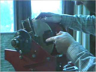 I assembled
the unit and tried it on the bench with just
12 volts on the 36 volt motor. Essentially it worked, pulses of torque
pushing the output arms around each time the magnets went by. It slowed
down but didn't stop as I squeezed the shaft coupling to try and stop
it, and it speeded up as I reduced pressure.
I assembled
the unit and tried it on the bench with just
12 volts on the 36 volt motor. Essentially it worked, pulses of torque
pushing the output arms around each time the magnets went by. It slowed
down but didn't stop as I squeezed the shaft coupling to try and stop
it, and it speeded up as I reduced pressure.
It seemed very promising. I put up a video of it: http://www.youtube.com/watch?v=Z73XZE4lnPo
But the astute viewer will notice the output stopped
gaining force with the motor speed at some none-too-high RPM.
Then I took it out and tried it on the car. The car showed
no
sign of wanting to move, but after minimizing the gap, the arms flailed
back and forth heroically about 10-15º as the magnets shoved them,
with the springing arms and also owing to a bit of slack in the chain.
Furthermore, above a certain RPM, the arms stopped flailing and
smoothed out, but there appeared to be less force than at low RPM.
The motor seemed able to accelerate and attain high speed without
working very hard: the coupling force seemed good at low speeds, but
almost nil at high speeds.
It appeared that the non-linearity and possible
saturation of interactive forces that was my biggest potential concern
actually occurred, and not far above the speeds and forces I'd been
attaining by hand in my November experiments. Two pounds force at 60
RPM certainly didn't seem to become anything like twenty pounds at 600
RPM.
It seemed it would be best to load the motor down so that
it couldn't readily attain higher speed than where maximum torque pulse
forces occurred, probably under 200 RPM.
In order to get sufficient interactive forces for that
purely from
magnetism as built, it seemed it would be necessary to go to multiple
interleaved
magnets and copper blocks, or to use a substantially larger diameter
and have several sets of magnets and blocks around the circumference.
For the latter there isn't room in the Sprint mechanism and
advisability of large diameter for 2000 RPM is doubtful, and the former
is beyond my
construction techniques and patience even if there was enough room - as
with doing gear transmissions, a properly equipped factory would be
best.
Remembering that evening that I had found a way to measure
torque to
the wheels on the Sprint, the next morning I jacked up a wheel and put
the torque wrench on the center nut. The torque went up to only about
10 foot-pound pulses - only 1/3 or 1/4 of what was needed to move the
car even on level ground. Seemingly contrary to all logic, torque
dropped off to
about zero as motor speed increased towards 1000 RPM, and stayed there
at any higher motor speed. How could the
magnets have less pull - even none - on the copper blocks at high
speeds than at lower speeds?
That afternoon was my talk at the Discover Tectoria
event. I ran the motor and mentioned several projects, but about the
torque converter I was less certain. I only said I had been on the
project for 2-1/2 years
now and had learned a lot. The talk was deemed a success, but I wished
I had been able to say I had solved the last problem and had, or would
soon be able, to move a car.
On the morning of
the 9th I realized what it probably was: at
low frequency, big circles of looping electrons would run around inside
the copper block. The whole copper block would be a big countermagnet,
as expected. But as frequency increases, they run around in
smaller and smaller
loops, canceling each other except at the outer surfaces. This "skin
effect" where current only flows near the surface of a conductor is
well known in higher frequency circuit design. That would decrease the
magnetic
field in the copper until it didn't interact well with the deep field
of the supermagnets. And without getting more thrust at higher
speed, the magnets would go by the blocks too fast for the low thrust
to overcome the inertia of the output and get the arms moving.
Perhaps something more sophisticated than a block
of copper was required on the output side? How about a big loop of
thinner copper, forcing the electrons to travel around the loop? Or
several thinner loops? This would be more like a shorted coil, so
effective at loading down a generator! That sounded right: for high
frequency coils, thinner wires are required because of the skin effect.
The 1/2" thick block of copper would only be good for the lowest of
frequencies - the sort made by hand motions for my simple tests. A 1" x
3"
loop 2" wide, or several thinner ones to total 2", with 1/8" thick
copper, should be good for a much higher frequency. In fact, loops of
heavy magnet wire might be best.
Another thought was that it could be given a laminated iron core - or
maybe simply solid iron - to increase the flux density.
The more I considered it over the day, the more certain I
was that this was the solution to the dropout of thrust at higher
speeds. What has more electromagnetic resistance to motion than a
generator with the output shorted? This was the same thing in reverse -
the coils would have great resistance to not following the
magnets spinning on the rotor, and shouldn't drop out at any
frequencies likely to be attained. Let's see: 2500 RPM (top speed and
more) is 42 cycles per second. Multiply by two because there's two
magnets on opposite sides of the rotor making two cycles per
revolution: 84 Hz. Now multiply by 10 because the entire cycle occurs
just when a magnet passes an arm - nothing like a sinewave: 840 Hz.
That's higher than I was thinking, and helps explain higher speed
dropouts of the solid copper blocks. It may even indicate thinner
magnet wire should be used.
The next logical step was simply to try a motor coil,
shorted out - hey, I wouldn't even have to make anything! But trying to
hold one near the rotor, the iron
powder core grabbed onto the magnets so strongly it prevented getting
any sense of
whatever else was happening.
Since I didn't have a way to mount a motor coil, I made
a coil to fit onto the arms to
try out, using the first bit of my 400$ spool of #11 magnet wire. I
decided to try a non-magnetic core first. I cut some black locust (a
hard dense wood) into
two appropriate size blocks, drilled holes to fit them onto the arms,
and wound a wire coil around one. It hardly worked at all. With the air
core and much less copper than the solid blocks, the force transfer
effects were slight. Worse, force seemed to stop increasing with speed
at about the same RPMs as the solid blocks.
It would seem air core coils would only work if they
contained as much copper near the magnets as the solid blocks. Another
thing that could be tried along
these lines would
be simply to split the copper bar into insulated 'laminates', either
flat or radial, to
try to get better higher frequency performance. I'm dubious this would
work any better, or even as well.
That leaves iron powder core coils again. Perhaps worth
trying.
But the next thing I did try, on the 11th, was annealing the
copper blocks. Copper is usually sold hardened so the rods and bars
don't bend in the stores, but hardened copper is about 5% less
conductive than annealed copper. Copper being 1.64 times as conductive
as aluminum seemed to translate out to about double the electromagnetic
coupling effect, so perhaps 5% would be 10% improvement. Of course,
that seemed pretty minor. Low-speed torque did seem better on the
bench, but that might just as well be attributed to the smaller flux
gap I think I got.
After the thought about the short duration of the
interactions of the blocks and magnets, I thought I'd turn the blocks
sideways so the magnets dragged along them for 3" instead of 2. (At
that point they'd go around enough of the circle that a wedge shape
might be noticeably better.)
The next step would be to use three magnets instead of
two. Two magnetic reversals instead of one would almost double the
force applied to a 3" long block. I had positioned the magnets for two
on the rotor, so the third would have less than ideal placement. But I
didn't try these things.
The next morning I woke up with the idea of using a single
wedge, a copper arc around the rotor, 5, 6 or 7 inches long at the
outside edge, working
against 2 or (more probably) 3 magnets, or even 4 if required. This
would:
* allow for increasing the coupling force with more magnets and copper
as required, similarly to interleaved fingers but without the
mechanical complexity (with the drawback of reducing the maximum torque
ratio),
* lengthen the time over which the coupling force was applied, which
would slow the motor more while applying torque to the output for a
longer period - hopefully long enough to overcome 'spring' in slack
mechanism, car springs and rubber tires.
* and double the time the motor had to freely pick up speed, giving
more impetus to each hit.
The circumference of a 10" diameter rotor is 31.4", so a 6" wedge
would occupy almost 1/5 of the circle, for a maximum potential of 5 to
1
torque increase. Of course, such a long wedge would be best be mounted
on
a rotor instead of on springy arms, to keep it straight. On the other
side, two or even three magnets might well be mounted on the springy
arms, suggesting that I should reverse the positions: copper on the
input
rotor and magnets on the output. That meant somehow getting the solidly
epoxied magnets off the rotor and redoing much. I might have to chip
them off. Oh well, that's what inventing's about. The hub and arms, and
the rotor itself, should still be employable.
Loosing the magnets turned out to be easier than expected:
the paint underneath detached from the zinc undercoat too easily and
they popped off with a hammer and chisel. As no magnet had flown off to
cause injury or damage in the tests, this was convenient, and a warning
not to use enamel spray paint. The polyester
coating of the genuine powder coating on the motor rotor hadn't come
loose even in October's magnet disaster. I don't have that, but I'll
try polyurethane spray next
time instead of enamel.
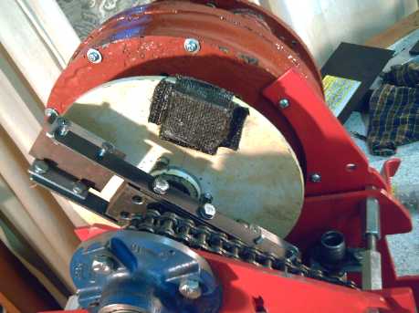
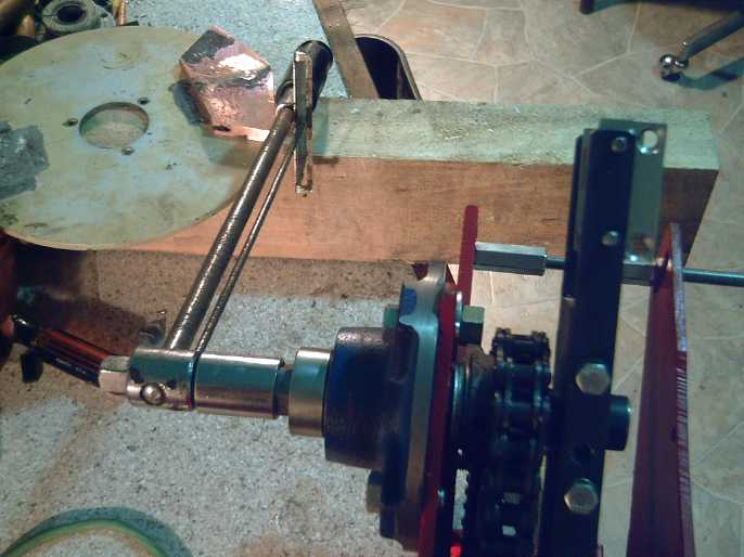
Front: Hex-nut shaped end of shaft with 22mm socket on torque
wrench.
(The wrench handle needs to be clamped down before I accidentally use
it with the motor in reverse.)
Rear-left of torque wrench handle: rotor with silver soldered copper
'wedge'.
(It needs a counterweight. Borax flux still covers some areas of the
copper.)
On the 13th, I decided I'd go work on battery making and
laid off the torque converter a week. But on the 21st, I cut two of the
copper pieces to form (roughly) the wedge. I tried to silver solder
them together
to prevent a sudden electromagnetic 'glitch' in the middle, but with
the thick slabs of copper and the December weather (2ºC), I
couldn't heat the copper up enough with the propane torch, even having
warmed the propane bottle in the house. I tried to switch to MPS gas,
but it hadn't been prewarmed and hardly burned at all.
The next day I decided to try the mini-kiln. I used the
potassium fluoride flux that I'd been sold with the silver solder (then
I read what it was and the dangers and said "augh!), and I clipped some
short sections of silver solder and laid them on the seams. I didn't
put it on for long enough, but after adding borax powder with a long
spoon for more flux and after going 10 more minutes and 10 more minutes
and 10 more minutes... the copper glowed red and the solder finally
melted into the seams. It was a solid block with the essentials of the
wedge shape, tho the seams really weren't properly filled.
Measuring Torque
I had finally (after having nothing for the first 2-1/2
years of the project) found a means of measuring torque, at the Sprint
car wheels: by putting a torque wrench on the center nut of a front
wheel.
It then occurred to me that if I ground the end shaft
collar into a hex shape, I could put a socket on it, and again with the
torque wrench, measure the torque right on the output shaft - including
for tests on the bench... assuming the shaft collar didn't slip.
Finally I realized I had enough shaft length free to slide
it over 1/2" and grind a hex shape into the outer end of the shaft
itself - that couldn't slip or come loose. This I did on the 28th,
buying a 22mm socket especially for the job and carefully filing the
hex down to its exact dimension and shape by fitting it on and filing
where it jammed.
Now if only I'd thought of this before I took the first
magnet/copper block arrangement apart, I'd be able to measure
improvement with the new arrangement. Trying to apply the desired 30 or
40 foot-pounds of force to the output arms steadily by hand shows what
a lot of force is needed. I couldn't get to 40. It was however not hard
to get the indicator to bounce to a 40 or 50 foot-pounds reading by
hitting the arm with a hammer. While such fluctuating readings can't be
trusted since the wrench's indicator arm bounces too, herein is the
torque converter theory: short, intermittent pulses of sufficient force
to move a car (at least after a final reduction gearing), with recovery
of lost motor momentum in between.
Second Trial
I was pretty sure it'd take at least two magnetic polarity
reversals (three magnets) along the copper wedge to get anything like
sufficient force, so I wasn't going to try one. (two magnets) More
likely it'll take three or four (four or five magnets). Beyond that,
the magnets would be spread out past the ends of the copper block and
no greater force can be attained.
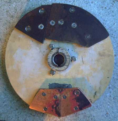
roughly balanced rotor with copper wedge.
Copper is denser, and the block is thicker, than the steel plate.
 On the 29th,
after having spent much time on batteries and
then all the Christmas diversions, I decided I couldn't let the month
expire without trying to finish the first 3-magnet version and try it
out. That day I got the copper wedge bolted onto the rotor, and since
that was heavy and unbalanced the rotor (the problem I'd hoped to avoid
by using two opposite-end sets of magnets and arms), I started on a
steel
counterweight for the other side. It wasn't heavy enough, so I bolted
it on offset to leave room for another one. I had them both on by
afternoon the next day. It still wasn't very well balanced, but was
good enough to run the motor at lower RPMs.
On the 29th,
after having spent much time on batteries and
then all the Christmas diversions, I decided I couldn't let the month
expire without trying to finish the first 3-magnet version and try it
out. That day I got the copper wedge bolted onto the rotor, and since
that was heavy and unbalanced the rotor (the problem I'd hoped to avoid
by using two opposite-end sets of magnets and arms), I started on a
steel
counterweight for the other side. It wasn't heavy enough, so I bolted
it on offset to leave room for another one. I had them both on by
afternoon the next day. It still wasn't very well balanced, but was
good enough to run the motor at lower RPMs.
Thinking about the magnets on the arm, I then figured I
could
hold two on the arms with a C-clamp without making anything, and
measure the torque (without the output actually having to rotate). So I
C-clamped
the magnets on and attached the motor with the newly outfitted rotor.
It seemed to give about 5 foot-pounds. With the 4 to 1
chain reduction, that would be 20 foot-pounds to the car wheel, which
would be half enough to move the car on level ground. That's double
what I had on the car with the two sets of two-inch lengths of copper
and double
magnets. Furthermore, it was attained with only a 12 volt battery.
What's next
The motor itself can put out (IIRC) over 10 foot-pounds of torque, but
that's with maximum amps, maximum heat in the coils and the motor
controller, and waste of energy. It might move the car on level ground.
Extrapolating (somewhat safer here multiplying elements than the
previous one, which assumed that force would increase linearly with
speed), roughly we might expect:
Magnets - Converter Torque Out (foot-pounds) - Torque at Car Wheels
following 4 to 1 chain drive
2 - 5 - 20
3 - 10 - 40
4 - 15 - 60
5 - 20 - 80
That was with about a .1 inch gap, which might be narrowed
a little. But not by much by the time an epoxied polypropylene fabric
covers the magnets to fix them in place and allowing for less than
perfect alignments.
So it would seem that evidently with 3 magnets the unit
just might move the car (30-40 ft-pds), four should traverse level
ground, and with
five it might even accelerate some or go up a bit of a slope. But with
five, the magnets would extend beyond the copper block on both ends.
Only for about 1/2" of the travel would all four
north-south-north-south transition edges be over the copper. The torque
would rise "gradually" in four steps and fall off again in four more.
(So much for the 'sudden' pulses of force.) No more than 5
magnets can face the copper at once.
If the magnets have to extend farther around the arc than
the copper block, I might as well have left the magnets on the rotor
and the blocks on the arms. But they all had to be rearranged anyway,
and that rebuilding makes figuring out the best
configuration tedious.
The copper block
could be extended a little farther. At 7.6" around the outside edge, it
could take 6 magnets, and would still have up to 4 to 1 torque
increase, and (in theory) 100 foot-pounds at the
wheels.
That's still not a lot, unless minor things like minimal
gap and double polarity reversals cause more force increase than
expected. (thinking wishfully...) The one item that might improve
things somewhat is raising the motor from 12 to 36 volts. The extra
motor power might just give sufficient extra torque with the present
copper arrangement and the four or five magnets. But the coupling of
the motor's force is still key and extra RPM obviously doesn't help.
However, if there were copper blocks on both sides of a
two faced cast PP-epoxy
magnet rotor, the forces could be about doubled. I'm no auto expert,
but I think
somewhere between 120 and 160 max foot-pounds at the wheels would give
the lightweight Sprint streetworthy performance. That seems attainable,
tho only with the 4 to 1 chain reduction, which would limit it to city
speeds.
First I'll try the simple path of putting 4 or 5
magnets on one of the arms and measuring the force attained. If it
seems worthwhile, I'll try it on the car. If it's good, great! If it's
"not bad", I'll try extending the copper and adding magnets. But if
it's just not enough "zip" for hills and the street (likely), the
double sided magnet rotor with copper blocks on both sides on the
output is next. It'll be more elaborate and time consuming to make, but
should be doable - the opposite copper would just "hook over" the
magnet rotor. More layers than that starts getting tough to put
together, but it looks like they probably won't be needed - at least
for this lightweight car.
Magnetic Impulse Torque Converter Theory
1. The motor has a 10" diameter rotor on on its shaft, the input shaft
to the converter. This rotor
and the motor's internal magnet rotor act as a flywheel to store up
kinetic energy as the motor rotates.
2. The rotor has a 6" long (O.D.) by 2" wide by .5" thick wedge of
copper on the side facing out.
3. The output rotor has several supermagnets arranged in a similar
wedge, oriented to cause rapid transitions from (eg) null to north to
south to north to south to null as the magnets spin past along the
copper wedge.
3. The magnet block is on the end of a stiff but slightly springy
arm, which is attached to a hub affixed to the output shaft. An
opposite arm has a counterweight.
4. The copper block is oriented so that its flat face almost touches
the flat face of the supermagnet block as it spins past, with a small
flux
gap.
5. This is the key part: As the copper wedge spins past the magnets,
most
especially at their sharp north-south magnetic transitions, the magnets
generate
electricity into it. The electrons looping though the fat copper
short circuit create an equal and opposite magnetic field, which
resists the motion of the magnets across the block. Since the rotor is
a flywheel and the copper won't slow down easily, the arm with the
magnets gets a
powerful tug, the force of which varies linearly with the motor speed
relative to the output speed (up to a rather low RPM point). The choice
of copper for
the block is
important: copper is only 1.64 times as conductive as aluminum but the
interaction effect this creates seems to be about twice as strong, and
the
heat losses will be lower. (Pure silver would be even better but it
costs a lot - it looks like a silver wedge would be pushing 1000$ (Dec
2011). Even with pricey lithium batteries, any efficiency gain could
hardly be worth the expense. Room temperature superconductors (where
are they?) would be super interactive and losses would be trivial.)
6. This is the mechanical helper part: Owing to the slightly springy
arms, the magnet block starts to move forward, freely for the first
instant, with the copper before
exerting force on the shaft, giving the arm a bit of inertia as well as
the continuing magnetic force. The resistance to
this motion quickly increases, linearly with the distance of flex
(Young's modulus), and the deceleration of the arm is added to the
magnetic force. The blocks rebound as the end of the copper wedge
passes. This increases the last shove of torque that the arms apply to
the hub and the output shaft. The flex also makes the forces somewhat
more smooth and gradual, as the magnetic impetus
otherwise would start and end more abruptly and might set up a fair
vibration in the car when high torque was needed.
7. The average radius of force is 4" from the center. For 4/5ths of
each
rotation, the motor spins freely and the flywheel picks up speed, then
the
magnets and copper wedge cross each other, slowing the flywheel down.
The wedge occupies a 6" O.D. arc around a 360º
circumference of π*10"=31.4". If we assume that the distance over which
the motor is slowed down is 6" (a rough approximation at best), then
for the other 25.4", the motor can
freely pick up speed. 31.4/6=5.23. This is the approximate maximum
torque increase over the
motor's torque. Since the magnets and block actually have at least
some interaction for several more inches, but peak interaction is in
much less
than six inches, and also because the spring action increases the peak
torque, it can only be a rough approximation.
For the Sprint, with the 3x or 4x chain reduction
following the torque converter, that should be sufficient torque
increase for practical use, overall speed reduction and torque
increase
being as much as 20 to 1, provided the actual output torque
from the rotor is sufficient, which depends on effectively coupling the
motor's torque.
For a direct on-wheel converter with no further reduction,
a 12" diameter system would give about 6 to 1, which might well be
insufficient. For larger rims, a 14" system with the same magnets and
6" wedges would give 7 to 1, and 16", 8 to 1. Those just might work,
but it's asking a lot.
Otherwise, the
2.8 to 1 planetary gear following the torque converter might be needed
to attain sufficient total force. Turning 5 to 1 into 14 to 1 should
enable the 10" diameter again.
Prospective Electric Outboard Motor from
Scratch Project
I had seen Princess Auto
"weld-to-hub" sprocket gears on line in the fall when I was looking for
some for the Sprint. You buy the sprocket gear by the number of teeth
and chain type, then the hub in the desired shaft size, and weld them
together. This way, the number of types they need to stock is
minimized. They were low cost, and I thought of the hypothetical
outboard project.
I had hoped there might be some that would fit in 2"
width/diameter. The sprocket-with-chain diameter set the minimum
possible width of the outboard leg at its widest point, since it had to
run down transverse to the propeller shaft. If it fit in 2" width, I
could use 2" plastic drain pipe for the prop shaft compartment.
In November a Princess Auto store opened near Victoria,
and on December 10th I went out with a friend to see it - especially
these sprocket gears. The smallest gears were a 12 tooth for "#40"
chain and a 16 tooth for thinner "#35" chain, both the same size. That
would take at least 2.5" inside width. I bought just one of the
16 tooth gears (3$, slightly smaller with the lighter chain on it) to
size up. Aggravatingly, the hubs for this size sprocket ended at 7/8"
shaft size, just a bit too small for the 1" Electric Hubcap motor
shafts, or I might have bought two with hubs. As it was, my thoughts
went towards bicycle gears and chain - perhaps they were smaller. The
"#35" chain looked about the same thickness as bicycle chain but was
wider, the sprockets being fatter, and the segments were shorter -
doubtless better for small diameter sprockets.
When I got home I checked out my bin of scrap bicycle
sprockets. There was only one that was a smaller diameter than the one
I'd just bought, and some of the 13 teeth had been damaged by a
cyclist, never mind a 5 horsepower motor. And even it would take a
little over 2" diameter space. A couple of others were the same size as
my new one, but looked much flimsier, and again one had teeth damaged
by just a cyclist. It seemed the "#35" set was the way to go, at least
for a motor over a horsepower.
Let's see... I could perhaps drill out a 7/8" hub to 1".
On second thought, better to turn down the end of a 1" shaft to 7/8".
Monday I went back and bought the other sprocket and two hubs,
5/8" and 7/8". I wasn't going to get bearings for the prop shaft, but
there were some 15mm ones for just 2.5$ each, so I did. I didn't get
chain. At least two people have told me to use motorcycle chain rather
than 'machine shop chain' in high speed applications.
A
2" ABS pipe fitting, that fits over the 2" pipe, should be
about 2.5" inside. That should just take the sprocket, and would also
be just about right for the prop off the
Honda. Any bigger and I'd have to go to 3" pipe for the foot. 2.75 to
3" O.D. would fit the prop better than 3" I.D.
I had a 7" length of 4" PVC drain pipe left over from the
first "Ultimate Battery Stick" - a great little piece to try out. I put
it in the oven at 300ºF for about 7 minutes. By then it had sagged
and was quite soft. With a 2.5" wide aluminum channel piece inside to
set the inner width, I shaped it into approximately the streamlined
teardrop shape while it was soft and pliable. Trying to make the sharp
back edge proved tricky, and when I squeezed it hard enough, the nearby
sections went concave. While I pushed them out again, it cooled and
became stiff again, so the back edge came out more rounded than I
wanted. So "by hand" does the main job and might be deemed acceptable,
but some sort of former(s) to closely
establish the teardrop cross section would be ideal. One could try a
slightly higher temperature to soften the plastic more. My experience
with this is pretty limited - in fact, I knew ABS would work at about
300ºf, but this is the first time I've tried PVC. Don't get it too
hot - fumes from liquid PVC are known and serious occupational hazard
carcinogens. The widest
width, for the chain, came out just right. It seems to me it's strong
enough to take the force of the prop with a 5 HP electric motor, which
should deliver substantially more thrust than 5 HP gas. I doubt I'd
want to go much higher with these components tho.
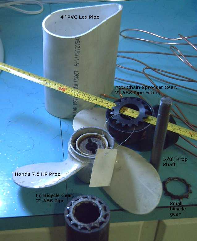
Some alleged parts for hypothetical DIY Electric Outboard Motor project
My idea for the outboard leg would be that it would be
shaped towards the bottom for underwater streamlining, but left round
towards the top, where it could be used with 4" pipe fittings as the
pivot for steering. Another idea would be to have two skinny legs, one
on each side for each side of the chain. These could potentially be
just 3/4" wide - at least below the waterline where it counts. There'd
be two, but they could be even thinner than one having the usual shaft
and gears. The sprocket size would matter less, too.
Hmm... the prop shaft had better be stainless
steel.
With no need for a number of things that gasoline
outboards need, like a forward-neutral-reverse system, the critical
parts would be:
* The propeller "foot" compartment with shaft, lower sprocket and
seals, and filled with a little oil to lubricate the chain.
* The waterproof join(s) of the foot to the leg(s).
* attachment of the motor compartment and motor at the top of the leg,
with chain tension adjustment.
* steering pivot, leg raising pivot, and transom attachment clamps for
the entire outboard.
There are a few other sundry things: steering arm or cable
attachments, speed and direction controls, preferably a catch to stop
it from kicking up in reverse, skeg extending below prop,
anti-cavitation plate, and a little cover over the chain and sprocket
at the top end to catch the oil that flies off and drip it back down
into the leg.
A minor issue is that it's likely to be front heavy and to
want to flip up by itself. But this depends on the placement of the
hinge, etc, and anyway might be solved by a spring or even a bungy cord
or two. Having the motor behind the chain instead of in front would
work too, but lengthens the wiring. For that, perhaps the motor
controller should be mounted right in or on the outboard. That would
make it
a single complete unit, too.
Issues with the leg are (a) that it might be hard to find
an oven big enough to hold the actual leg piece to heat it to
300ºf softening temperature (especially for a 'long shaft'
outboard), and (b) it's almost 3" wide. How much of an issue that'll be
for friction in the water, I don't know. I suspect that low speeds
should be fine, but at higher speeds, it may prove a significant drag.
It's the main problem I see with chain drive, and with the smallest
readily
available sprockets being bigger than I'd like. There's always 6" PVC
pipe for a longer but no wider teardrop profile, or the two leg idea.
I'm thinking the total weight would be under 50 pounds,
including a 30 pound Electric Hubcap motor. Many motors could of course
work acceptably. Using a highest efficiency Electric Hubcap motor is
valuable anywhere something's being run off batteries and maximum range
or duration is desired.
In concept I very much like this whole project - partly
because I don't see anything that doesn't look readily doable, or that
should take too long. On the other hand, new designs always take longer
than one expects, and unexpected snags are to be expected.
But I think I'll collect the rest of the parts, and work
on it now and then when I'm fed up with other projects or not sure
what's next on them... or (gasp!) finished some of them.
I thought instead of getting a 5/8" stainless steel shaft
for the propeller, I'd just buy a 5/8" stainless steel bolt, 8" long.
And that would have a threaded end to hold the prop on. Gasp! The bolt
and nut cost 29$, more than all the other parts so far put together.
Being near Industrial Plastics one day, I thought of 2.5"
I.D. (2.75" O.D.) plexiglass tube instead of ABS or PVC plumbing pipe.
I found a 10" piece in the 'offcuts' bin - 8$. That solves the main
propeller housing body - it's just about the right size for the bottom
sprocket gear, and pretty much matches the base end of the propeller.
Being able to see what's happening inside is a bonus, especially on a
prototype. But even on a production unit it'd be nice to be able to see
if any seawater has gotten into the oil.
Another day I bought a longer piece of 4" diameter PVC for
the leg, at the same time as buying some for more Super Battery Sticks.
LED Lighting Project
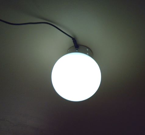
Light fixture on the wall? - easy as
hanging a picture!
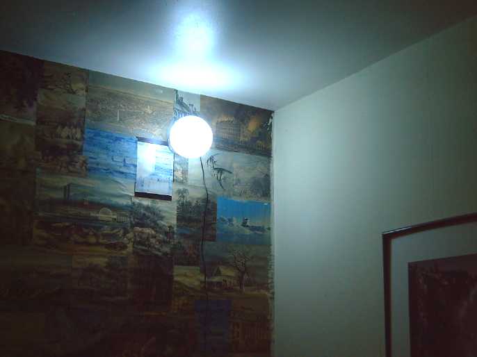 I took the
cold white light made in November, took the globe off it, and mounted
it on the kitchen wall in a corner by the table that has always been
rather dark, with one screw. An outlet was nearby at table height. I
didn't get fancy - just plug in the adapter to turn it on.
I took the
cold white light made in November, took the globe off it, and mounted
it on the kitchen wall in a corner by the table that has always been
rather dark, with one screw. An outlet was nearby at table height. I
didn't get fancy - just plug in the adapter to turn it on.
Then it occurred to me that if I changed the small
mounting holes in the back to large holes with a slot, as is so common
on electrical box covers, that one could simply hang the light fixture
on a wall from a nail or a screw anywhere, like a picture, without even
taking the globe off - Buy it, put it on the wall, and plug it in. If
you don't like the location, put in another screw or nail and move it.
(Try that with 120 volt light fixtures!)
Energy Star
After waiting some weeks for a response to my application
(on paper in the mail) to Energy Star, I finally e-mailed them.
Evidently I signed my name on the wrong dotted line and I had to start
all over again, a month later. Ouch!
But the document actually had no place for a signature. I
queried that.
Nickel - Metal hydride Battery Project
The connections inside the battery sticks seem very good,
but someone told me that if you put a bit of vaseline on each
connection, the contact is improved, and it prevents corrosion. He said
vaseline is a conductor.
My ohm meter doesn't seem to think it's a conductor.
Nickel and stainless steel don't corrode readily, still, it might help
prevent corrosion, especially if the nickel plating eventually wears
through with vibration when in use.
I pass on this tip FWIW and will try it myself. (If I like
it, what am I going to do with all those battery sticks that are glued
shut?)
First Super Battery Stick
Feeling a need
to actually complete something (besides a battery compactor I didn't
like and a couple of LED lights for Christmas presents), on the 18th I
made the first 12 volt, 70 amp-hour Super Battery Stick. I wasn't
tracking the time, but it probably took around 3 hours initially, then
on the 22nd I modified it. It should theoretically source 210 amps
continuous (the Electric Hubcap motor draws less than 150 max), and
would probably put out over 600 amps if it were shorted. I think I like
like the terminals being on opposite ends rather than set to short if a
wrench or piece of metal bridges them.
It swallowed all my remaining D cells from the cupboard
and I had to take some from a couple of existing single set battery
sticks, too. It was a good time as the charge on some of the cells
sitting in the cupboard since July was getting rather low. It took a
while just to unbox and unwrap the 70 cells and slide them all in. I
checked the voltage on each set of ten to make sure I hadn't put any
cells in backwards - even one would create a big problem. Since the
cells were at different levels of charge, including differently charged
cells in series, I charged it pretty slowly, limiting the current to a
couple of amps until the voltage eventually hit the 13.8 volt limit.
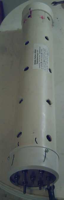
Initially, I wasn't sure whether to keep the pipes nicely
enclosed to keep them clean inside, or drill ventilation holes. But
even with low charge currents, I could feel a couple of the cells or
strings getting warm through the PVC pipe. I recalled a friend saying
that at UVic, they'd wrecked some lithium batteries by overheating
them. They had planned a ventilation system but hadn't installed it
yet, and all the batteries' heat together in one place were too much
during testing of their EV project.
These weren't lithiums, but learning from someone elses'
mistake is cheaper than from your own, so I drilled ventilation holes
in the pipe. They are after all going to be protected under the hood of
the car, and I can put moisture guards above and below them. They are
also going where the radiator was, and I should be able to direct air
flow across them. I suspect they won't even get warm except maybe
during charging, but better safe than sorry.
You can buy this pipe as perimeter drain pipe with some
holes, but not enough of them for good air flow, so even in that I'm
drilling more.
Getting 70 more cells for the next Super Battery Stick
will involve unsoldering one of the earlier battery packs, and for the
third one, I'll need to gather up the bulk of the ones I have - total
210 out of 275, not counting the 30 in my regular car battery. With
solder on some of the cells, spacings will be uneven and they will need
the bolt tension adjustment (below).
It was more involved than the single sticks. First, it had
to have a couple of spars to keep the 7 columns of cells lined up.
Then, all 7 had to make secure contact, so they had to either be on
springs or adjustable at one end. I screwed both end caps on with small
screws. I have a fair investment in labour in this pipe itself, never
mind the 500$ worth of cells, so there's no way I'd glue it shut. When
eventually the cells are worn out, I may want to dump them and put new
ones in the same pipe.
Spring clips (go inside 'minus' end flange) to help ensure good
contact on all 7 strings of D cells.
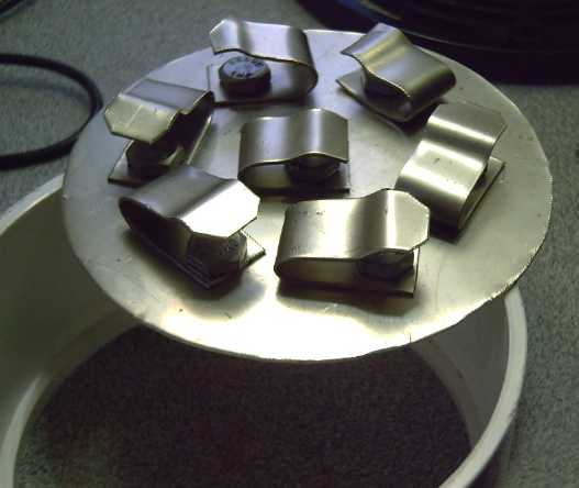 The plastic
end cap covering one end was just
a nuisance, so I bought five more "pipe adapter flanges". I found the
first one at Rona - I didn't
know what they were called. It seems they're intended to allow 4" ABS
pipe fittings (slightly larger I.D.) to be used with 4" PVC pipes. As
you may guess, they have an inner lip that holds the metal around the
edge. I had to cut and drill a new metal piece for the fit.
The plastic
end cap covering one end was just
a nuisance, so I bought five more "pipe adapter flanges". I found the
first one at Rona - I didn't
know what they were called. It seems they're intended to allow 4" ABS
pipe fittings (slightly larger I.D.) to be used with 4" PVC pipes. As
you may guess, they have an inner lip that holds the metal around the
edge. I had to cut and drill a new metal piece for the fit.
The metal I used was 18 gauge nickel-brass (AKA
"nickel-silver"). I had hoped to thread the holes in the un-sprung end,
and you'd be able to turn the bolts from the outside to check to see if
any sets are loose, and adjust one or two if necessary. The threads in
the sheet metal, thick tho it is,
turned out to be unworkable, so
I'll need to solder brass nuts to the end plate to be able to make the
adjustments.
The 28 pound Super Battery Stick has the look of a real,
industrial size battery. The pictures pretty much say the rest. Three
should certainly run the 36 volt car.
Turquoise Battery Project
Nickel Zinc Alkaline Cells
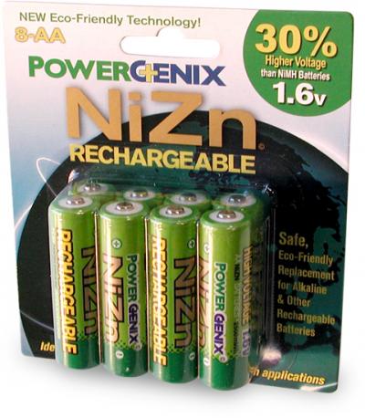 Wikipedia says
that since Y2K, nickel-zinc
batteries have been improved by additives to stabilize the zinc. I'd
seen a couple of web sites showing
nickel-zinc dry cells, and some ideas for improving zinc electrodes,
but never actually any for sale.
Wikipedia says
that since Y2K, nickel-zinc
batteries have been improved by additives to stabilize the zinc. I'd
seen a couple of web sites showing
nickel-zinc dry cells, and some ideas for improving zinc electrodes,
but never actually any for sale.
They are of interest because of their higher voltage and
consequent high energy density by weight, and their potentially lower
cost than NiMH. Rated 1.6 volts, only three are needed for every four
NiMH cells to attain the same voltage. Zinc electrodes being highly
conductive, they're good for high currents - fast charge and discharge.
Now they are for sale. The one company making
them to sell is PowerGenix.com. The only size for sale appears to be
AA. At 2$ each (from Amazon.com) for a 2.5 watt-hour cell with only
"400-1000" charge cycles, they're not very competitive with 3 watt-hour
NiMH AA cells at 1.25$ (from all-battery.com - "1000" charge cycles)
...unless you have a device that simply won't work with the lower
voltage. (such as a wireless microphone I have that insists on standard
dry cells only (1.54V) - not even alkaline (1.43V).)
Given that the
Wikipedia article says "100 WH/Kg", the same as NiMH AA, they must
weigh
25 grams where the 3 WH NiMH ones weigh 30, tho I could find no figure
anywhere. Another disadvantage is that there's no allowance for
overcharging in these particular cells, and only their chargers must be
used. (A constant voltage charger might work.)
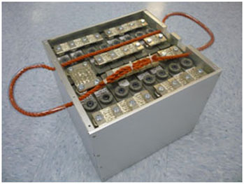 PowerGenix is
also testing "sub-C" size NiZn for hybrid car batteries, and larger
rectangular cells (doubtless flooded cells) for US army tanks, to
replace lead-acid. They may well be being prevented from making these
as car and EV batteries, but the technology looks good and is in
principle potentially somewhat less costly than NiMH since zinc is dirt
cheap whereas nickel-lanthanum-cobalt alloy hydride is rather costly.
(Note that this battery has 8 cells (doubled up) instead of 10 to get
12 volts
despite the rated voltage being 33% higher. But the choice is 11.2
volts nominal or 12.8 - it really needs 7.5 cells. Six NiZn and two
NiMH would make 12.0 volts nominal.)
PowerGenix is
also testing "sub-C" size NiZn for hybrid car batteries, and larger
rectangular cells (doubtless flooded cells) for US army tanks, to
replace lead-acid. They may well be being prevented from making these
as car and EV batteries, but the technology looks good and is in
principle potentially somewhat less costly than NiMH since zinc is dirt
cheap whereas nickel-lanthanum-cobalt alloy hydride is rather costly.
(Note that this battery has 8 cells (doubled up) instead of 10 to get
12 volts
despite the rated voltage being 33% higher. But the choice is 11.2
volts nominal or 12.8 - it really needs 7.5 cells. Six NiZn and two
NiMH would make 12.0 volts nominal.)
Going over zinc electrodes in Alkaline Storage
Batteries from 1969, I see they used to use no ingredients other
than zinc oxide or zinc powder, 1-4% mercury oxide to raise hydrogen
overvoltage, and 2% PVA (poly-vinyl alcohol) or PTFE (teflon) binder.
Small wonder then, with the zincate ion that lets the zinc migrate,
that they only lasted 10 to 50 charges as dry cells, or a few hundred
as pocket cells.
A source from 1999 that claims very good results uses 1.6%
poly-acrylic acid, evidently water soluble but probably not in alkali.
It also has carefully controlled water concentration in the dry cell of
about .7g/AH (which they say is important) and uses .05-.5% of
gallium, tin, or bismuth (or oxide thereof) to raise the hydrogen
overvoltage. I prefer antimony, about 1% because my hand mixing is
probably
not as thorough as commercial preparation.
Despite the conductivity of zinc and zinc oxide, I've
'instinctively' been adding some graphite powder and treating it, to
create mixed material pores that I hope will prevent the zinc oxide
from agglomerating into bigger particles of zinc as it charges. (This
might also work with iron, increasing the capacity per amount of iron
electrode.) Or am I just making it more fragile and prone to crumbling
before it's in the cell?
I also paint zirconium silicate on the electrode separator
sheet to prevent zinc - and permanganate - ion migration between
electrodes. (Zirconium hydroxide has been used for this purpose by
others.)
In salty solution instead of alkaline, the same chemicals
will provide another 1/4 volt or so, making cells rated 1.8 or 1.9
volts, and I hope the zinc electrodes would last far longer with the
graphite and the zircon.
A mixture of permanganate and nickel oxides for the plus
side should yield higher energy density than nickel alone. That with
zinc is about where the Turquoise Battery Project is presently headed.
On the other hand, if manganese can be made to work in
place of the zinc, it would add to the cells yet another 1/4 volt and a
further significant increase in watt-hours per kilogram. That depends
on finding a more effective hydrogen overvoltage raiser.
New Electrode Compactors
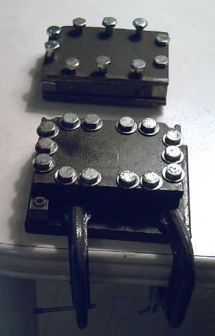 On the 14th I
decided to get back to the battery project.
The big compactor, made for electrodes up to 3" x 9", seemed like
overkill if I was going to settle on 1.5" x 3" electrodes for good. It
was heavy
and a lot of metal to wash.
On the 14th I
decided to get back to the battery project.
The big compactor, made for electrodes up to 3" x 9", seemed like
overkill if I was going to settle on 1.5" x 3" electrodes for good. It
was heavy
and a lot of metal to wash.
I went out to the garage and found the old one. I cut a
2.5" section off one end to do the 1.5x3". Then I made a wall for the
new end and drilled holes in it. It gradually dawned on me as I worked
that I'd left no lip to clamp it down with, and that that was
important. The drill will spin the whole loose compactor around, even
the biggest one, when doing up the compacting bolts. For the time
being, I
clamped down the leftover end and put this one inside it so at least
it couldn't spin when I turned the bolts. It worked, but I still didn't
have a compactor I was happy with.
On the 19th I sliced up the newer compactor too, and made
a 3 x 1.5 one. Somehow it took about 3 hours. It has the following
advantages - two of which were the original reasons for making a second
compactor in the first place:
* The bottom plate is 1/2" thick. Not only does it flex less, but the
bolts don't screw right through, so they don't push the base up from
the table.
* There are 14 pressure bolts instead of 10, providing greater
compaction. The lesser number may have been one reason my zinc
electrode from the first one (below) was so fragile.
* and it has the lip for clamping it down.
Open view of compactor with inner punch-die.
On New Year's Eve, I went to a party, where I saw a couple
of interesting looking heavy presses on the hostess's hallway floor.
They've
given me fresh ideas for a new design with one or two very large screws
with "steering wheel" type handles. That should be much faster and
easier than screwing in and unscrewing all those small bolts.
Grafpoxy improvement
The grafpoxy wasn't covering very well. I decided to
simply put a second coat on the grills I made a couple of months ago to
catch any pinholes. The second coat clogged a lot of the pores in the
mesh. As I worked, it occurred to me that the resin could probably be
thinned to make thinner, better covering coatings.
Evidently acetone is a common solvent to dilute epoxy
resins,
also MEK, xylene... seems like many solvents might work. Let's see... I
have acetone and toluene. My 1/2 litre of MEK evaporated from the
closed
tin - grr!
Grafpoxy Conductive Plastic
Something I'd considered buying a while back was graphite
impregnated
conductive plastic. When I painted the grafpoxy onto the grills, I did
it on a piece of polyethylene. This left black smears of grafpoxy where
it had been done. They could be flaked off as very thin pieces of hard,
brittle
plastic. With an ohm meter, the thin plastic read in the 10s to 100s of
K ohms - high, but perhaps usable for a seal between two electrodes,
conducting across its entire surface area. One could then make bipolar
cells: simply abutted individual cells with conductive faces, or more
or less as I wanted: as cells glued together with a common conductive
wall between each pair.
The resin mixture would simply be poured into a flat
polyethylene tray as a mold to make each sheet of conductive grafpoxy
plastic, the depth being the thickness. Again, if it didn't conform
well, it could be deluded with solvent.
If it wouldn't glue with methylene chloride or MEK, some
more epoxy should work as glue.
Perhaps going to an extreme, one could make a thin piece,
put a copper grill across it, with a welded or soldered terminal bolt,
pour in some more resin,
and have a sheet of conductive plastic with an embedded terminal post,
to be used as one face of a
battery. The electrode would press against it from inside, conducting
through across the entire surface area. The electrode and its grill
would need no attached leed wire, and no hole for the terminal need
penetrate the case.
Zinc Electrode (14th-15th)
For the next electrode I put in 40g of the zinc-graphite
mix I made last month (=~31g ZnO) with a bit of Sb4O6, .3g Sunlight
dishsoap, and .8g Diesel Kleen. With some water still in it, it was too
wet to compact, so I let it dry overnight. It came out about 4mm thick,
but rather wedge shaped from 5 to 3mm. Resistance from surface points
to the terminal were around 45-65 ohms. I didn't dare press the meter
probes very hard.
I feared the powder might have become somewhat
'carbonate'ed again after drying in air, so from now on I think I'll
'alkalize' the
finished electrodes and not bother doing the
powder in advance.
31g of ZnO at .659 AH/g = 20 AH. If the positrode matches that - and if
both work to theoretical capacity - that's twice the amp hours of a
NiMH D cell at 1.8 volts instead of 1.2, for three times the energy...
and in about the same volume of space. I'll be very happy to get 2x.
That would also beat lithium ion types.
I decided to try using the previous positrode. It looked
good, but the resistance had risen to the lower to mid 'x1K's
level. At least it was dry, so that was real and not ionic conduction.
It was too fat - the pair wouldn't fit into the 1/2" wide case. Rather
than make a thinner positrode, on the 16th I made a fatter case - I
knew I wanted them fatter than 1/2" but I'd been unable to find 5/8" or
3/4" thick acrylic or lexan plastic. I used two thinner pieces glued
together.
I put the electrodes in the new case and filled it with
potassium hydroxide to de-carbonate any zinc oxide that had become
carbonated again. It leaked out. Sigh! I'd forgotten to fill it with
water and test it. I'd really like seamless rectangular boxes
for cases. I left it for a couple of hours anyway, then tried to rinse
it out by filling it with water and letting it drain. It stayed full.
Arg!
Finally I pulled out the electrodes and rubbed methylene
chloride around at the suspect areas (most of the joins) to try to fill
them in. I filled it to dilute the KOH a second time, drained it. and
then filled it with my 'regular' salty electrolyte. Checking the pH, it
was still 12 or 13 - almost still an alkaline battery.
In each operation, bits of electrode and powder were lost.
They're just so fragile before use.
Skipping ahead for a moment, on the 17th it occurred to me
that instead of potassium hydroxide
to decarbonate the zinc or zinc oxide powders, I could use calcium
hydroxide - lime. This would be less caustic (pH 11 or so), and any
insoluble calcium carbonate
(limestone) left in the electrode could only help make it stronger.
I left it to sit or set for an hour. It read .20 volts.
Then I started charging it at 16mA (=1.6v/100Ω). It soon read 2 volts,
which dropped swiftly to 1 when the charge was removed. This said the
internal resistance was very high. I guess I shouldn't have reused that
positrode. I decided to leave it on charge for the evening, but I soon
had to drop it to 10mA and realized it was pretty hopeless. (I found
out why - below.) Obviously a new positrode was required.
But how to keep it from going the way of so many others?
Well, re-reading my own Turquoise Energy News #45, for the one
positrode that worked so well, as well as having the first grafpoxy
grill, I had put in some fairly solid stuff and clamped the lid down on
it, so that there was little room for the electrodes to "fluff up"
into, and only against pretty strong foam rubber. It would seem, as I
surmised when I made it, that that's the key: not only to compact
positrodes well, but to be sure they stay compacted. If they 'fluff up'
in use they're hosed. (If I had fewer projects, I wouldn't forget such
important details between sessions!)
I hope I can make a thinner electrode and jam it in with
the zinc one (which I hope is still okay) into the thinner case... with
no room to spare for fluffing.
I tried inserting a piece of plastic behind the existing
electrode to squash it back together. In doing that, I discovered that
the terminal post had come loose: the grill had corroded completely
through from top to bottom. That was an even more basic problem! If I
can't get the epoxy to seal reliably, maybe I should try ABS-poxy or
something? Or make grafpoxy grills with no metal inside... but they
probably wouldn't be very conductive. The epoxy seems brittle when it's
thin, eg as a coating on a somewhat flexible wire. But the next grills
got two coats, and I haven't tried thinning the epoxy yet.
I put another grafpoxied grill behind the briquette to get
contact, but it still didn't work at all well. Finally I replaced the
zinc electrode with a sheet of zinc. That didn't work any better, so
the positrode was indeed the problem.
That was pretty much that as Christmas and visiting
relatives intervened. I really need to be able to get consistent,
working results! I'll try again to get them with NiMn-zinc, thinning
the grafpoxy, and if that goes well, I'll be trying manganese again.
Hopefully in January.
Looking for better grills
Aside from grafpoxy, the expanded copper mesh I've been
using for grills, about 10 x 15 wires per inch, is really too coarse.
The electrodes would adhere better and connect better with a finer
grill. Epoxy doesn't adhere to aluminum, and I have a feeling stainless
steel would fare no better. That eliminates window screen (also coarse)
and the 60 wires/inch stainless mesh from Metal Supermarket.
So I'm looking for a finer mesh grill, eg, 25-40 wires per
inch, in copper, nickel, brass or other non-ferrous alloy. It must
exist
somewhere, but I can't think where at the moment. (I've found little
brass wire sieves at the ceramics supply. Where do they get the mesh to
make them?)
Next Manganese Negatrode Attempt
My previous efforts to raise hydrogen overvoltage enough
with eggwhite and antimony oxide so that manganese could work as a high
energy negative electrode weren't successful. I was somewhat surprised
the eggwhite didn't seem to work as it sounded so promising in the
research paper abstract.
I wanted to try antimony sulfide, but I couldn't seem to locate any.
I decided to try again.
Evidently it's used to create a color in fireworks. It's not costly
from pyrotechnics supplies and
I don't need much, but I couldn't find any in Canada, and the one or
two I found in the USA say they ship to USA only.
Antimony sulfide is also known by its mineral name,
stibnite. The local Rockhound Shop had none. On E-bay I found some
people auctioning off samples of stibnite embedded in quartz, even a
couple in Canada:
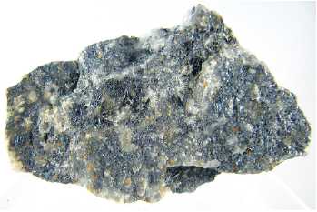
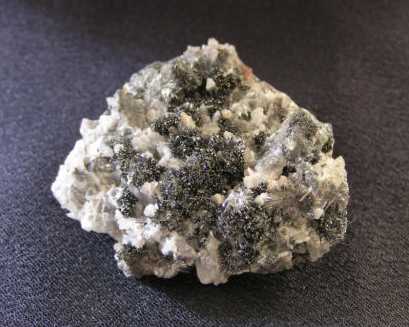
The Stibnite in Quartz currently available in Canada on E-Bay - if you
win the auction
So, perhaps again thanks to Canada and BC banning or
restricting every tenth chemical for one myopic reason or another,
instead of simply buying a pound of fine powder for 10.50$, I'm bidding
on little chunks of "mineral
specimens" having a bit of
antimony sulfide of dubious
purity. (And to think, when I was a kid, we went
around proudly
saying "We live in a free country!" One wonders if Ovshinsky had been
working in this particular "free country", whether he might have been
unable to get all the things he needed to come up with the metal alloy
that made crappy nickel-metal hydride batteries into the fine cells
they are today.)
I won the bid for the one on the
left - just 5.50$... + tax + 13$ shipping = 19$ - for a trifling
quantity. At least I got some. The rock arrived on the 30th.
Evidently Sb2S3 is 'slightly
soluble', and with a magnifying glass, I can see faint colors (yellows,
reds, purples) indicative of antimony compounds formed by conversion of
stibnite partially to oxides. What I'm
more or less expecting to have happen is that it will become converted
to intermediate product(s) like kermesite, Sb2S2O,
or a thiosulfate, with oxygen replacing some of the sulfurs,
and thence becoming insoluble. It may also 'set' and perhaps improve
the strength of the Mn electrode - thiosulfates are used to set dyes in
textiles. These are but guesses.
http://www.TurquoiseEnergy.com
Victoria BC