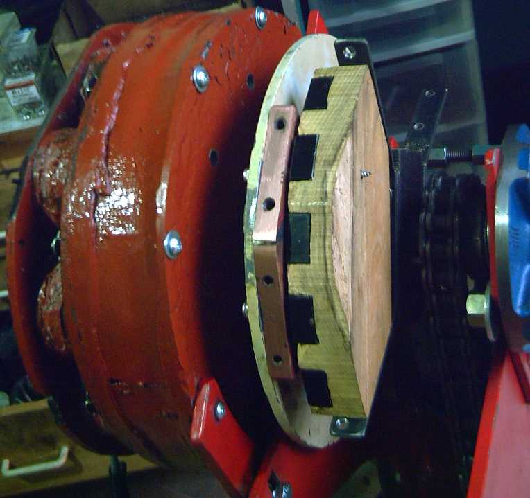
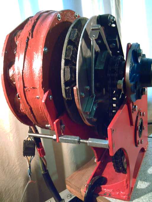
Experimental Version 2: Copper wedge on motor rotor,
and 'wedge' of 5 supermagnets on output "rotor".
 I went to a new years eve party/music jam. I noticed the hostess had a
couple of heavy looking presses in the hallway with big "steering
wheel" cranks to tighten them. I wondered if they might be suitable for
electrode compacting, instead of doing up 14 small bolts around the
edges of the compactor box.
I went to a new years eve party/music jam. I noticed the hostess had a
couple of heavy looking presses in the hallway with big "steering
wheel" cranks to tighten them. I wondered if they might be suitable for
electrode compacting, instead of doing up 14 small bolts around the
edges of the compactor box.
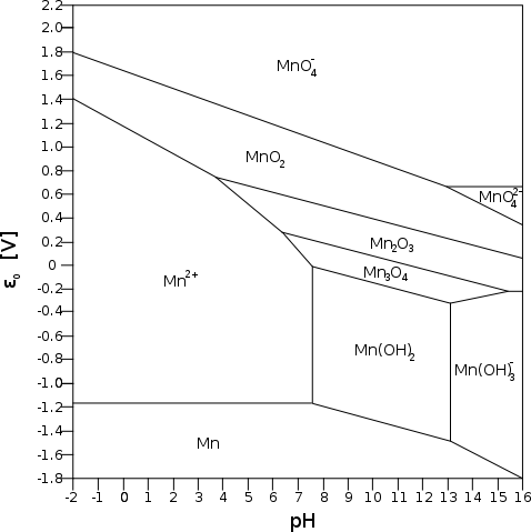 Zinc is
usually considered to
have the highest usable
negatrode voltage, -1.05 volts in salt solution. Manganese is perhaps
the next voltage up of
the usable elements. I was
guessing that its potential in salt was
the average of acid and alkali, -1.37 volts. I knew that was risky but
had nothing else to go on.
Zinc is
usually considered to
have the highest usable
negatrode voltage, -1.05 volts in salt solution. Manganese is perhaps
the next voltage up of
the usable elements. I was
guessing that its potential in salt was
the average of acid and alkali, -1.37 volts. I knew that was risky but
had nothing else to go on.
 On the 22nd I tried to dig the
iron out of an iron pocket
electrode to replace it with the manganese, but it was tough going.
Probably it was charged to iron particles that would be sintered -
electroplated - to the pocket walls. Fully discharged to Fe3O4 it
should have been easier.
On the 22nd I tried to dig the
iron out of an iron pocket
electrode to replace it with the manganese, but it was tough going.
Probably it was charged to iron particles that would be sintered -
electroplated - to the pocket walls. Fully discharged to Fe3O4 it
should have been easier. I started
imagining a number of possible
molded plastic shapes, lightweight "pocket" cages with the vertical
bars and
perforated sides, or a grid lattice holding in paper sides, to hold the
electrodes and prevent them from
expanding once inserted into the cell, which appears to be my ongoing
main problem. These, or perhaps even a bezel, might also make handling
and inserting the electrodes simple, including for DIY production. And electrodes with internal grafpoxy coated
grills - or even nickel plated grills - should be cheaper to make than
nickel plated pocket cells. This construction could be applied to any
fillings chosen, so it should be
well
worth it for somebody to set up some sort of production line to make
batteries in that form without waiting for any other battery success in
my research. (Making a mold(s) for this seems like a fine job for my
new milling machine!)
I started
imagining a number of possible
molded plastic shapes, lightweight "pocket" cages with the vertical
bars and
perforated sides, or a grid lattice holding in paper sides, to hold the
electrodes and prevent them from
expanding once inserted into the cell, which appears to be my ongoing
main problem. These, or perhaps even a bezel, might also make handling
and inserting the electrodes simple, including for DIY production. And electrodes with internal grafpoxy coated
grills - or even nickel plated grills - should be cheaper to make than
nickel plated pocket cells. This construction could be applied to any
fillings chosen, so it should be
well
worth it for somebody to set up some sort of production line to make
batteries in that form without waiting for any other battery success in
my research. (Making a mold(s) for this seems like a fine job for my
new milling machine!)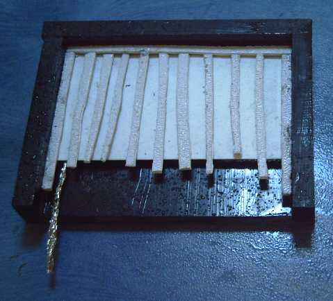 On further
consideration, I decided that maybe making the
cases to exact 'bezel' size but leaving one side off might be the
simplest. The bottom electrode, exact size separator paper, a frame of
bubble path bars (glued around the edge), another separator, the top
electrode, and something springy if any space remained, would all be
layed gently into place without the likelihood of breaking the
electrode briquettes, then the
other side would be clamped on top and glued. Then it would be set
upright and the top glued on. The more of the four plastic pieces that
were pre-molded, the
easier it would be, but it could all be glued flat pieces.
On further
consideration, I decided that maybe making the
cases to exact 'bezel' size but leaving one side off might be the
simplest. The bottom electrode, exact size separator paper, a frame of
bubble path bars (glued around the edge), another separator, the top
electrode, and something springy if any space remained, would all be
layed gently into place without the likelihood of breaking the
electrode briquettes, then the
other side would be clamped on top and glued. Then it would be set
upright and the top glued on. The more of the four plastic pieces that
were pre-molded, the
easier it would be, but it could all be glued flat pieces.