Turquoise Energy Ltd. News #49
Victoria BC
Copyright 2012 Craig Carmichael - March 1st, 2012


http://www.TurquoiseEnergy.com = http://www.ElectricHubcap.com = http://www.ElectricWeel.com

Feature: 2 Volt Salty Batteries - 3 Major Advances in a month improve state of the art!
* Perforated Hard Plastic Pocket Electrodes simplify "DIY" battery making
* Manganese Negative Electrode Works: Green, cheap, high energy, long life 2 volt cells
* Nickel Manganate Positive Electrode: high conductivity improves battery performance

Month In Brief (Summaries)
* Much of the month was spent making the best new chemistry - and new construction - batteries yet
* I talk on the Turquoise Battery Project and DIY battery making at Ideawave 2012
* Electric vehicle club meeting(s)

No Project Reports on: Electric Hubcap system, Weel motor, Sprint car conversion, Electric outboard from scratch, DSSC solar cells, Pulsejet steel plate cutter, NiMH batteries

Magnetic Impulse Torque Converter Project

* Idea: the magnetic impulse rotors should make enough torque to run dirt bike as-is, without 2nd mechanical hammer stage. (as an interim project, for March).

LED Lighting Project

* Adding switches to light fixtures
* Hanging LED wall lights to replace table lamps?
* Turquoise Energy is finally accepted into Energy Star program

Turquoise Battery Project
* Perforated Plastic Pocket Electrodes: Evolution of a whole new "DIY" way of making batteries.
   - rigid perforated plastic container encapsulates compacted electrode ingredients
   - perforated flat plate electrodes (perf. plastic sheets glued with ribs into thin boxes)
   - perforated square cylinder electrodes (perf. plastic sheets heated & bent into square tubes)
* Problems with negatrode self-discharge solved! The metal or carbon current collector, not the chemicals, has been bubbling hydrogen! Must use zinc or silver or alloys thereof.
* High energy manganese negatrode works: renders NiFe, NiCd, NiMH and NiZn obsolete?
* Cells can be alkaline during cycling with KCl salt electrolyte - no need for caustic KOH. Ca(OH)2 additive can make intermediate alkalinity for potentially improved characteristics and cycle life.
* Got thinner plastic, .020" styrene -- It wouldn't form into cylinders properly.
* Got .030" PVC plastic -- characteristics seem ideal.
* Nickel manganate: higher positrode conductivity for better performance... or is it a better chemistry? - Nickel [per]manganate positrodes instead of nickel [oxy]hydroxide
* Making NiMn2O4 -- (NiMn2O4, Positive Electrode Mix, for sale, 20¢/gram either one).
* First working cell with 1/4" square cylinder electrodes, nickel manganate (+) and manganese (-) charges to about 2.3 volts.
* Ordered laser diodes, to have CNC machine burn the perforations in the plastic, ideally sized and spaced, automatically. (Too simple!)


Newsletters Index/Highlights: http://www.TurquoiseEnergy.com/news/index.html

Construction Manuals and information:
Electric Hubcap Motor - Turquoise Motor Controller
- 36 Volt Electric Fan-Heater
- Nanocrystalline glass to enhance Solar Cell performance - Ersatz 'powder coating' home process for protecting/painting metal

Products Catalog:
 - Electric Hubcap Motor Kit
 - Sodium Sulfate - Lead-Acid battery longevity/renewal
 - NiMH Handy Battery Sticks
, Dry Cells
 - LED Light Fixtures
Motor Building Workshops


...all at:  http://www.TurquoiseEnergy.com/
(orders: e-mail craig@saers.com)


February in Brief

   Although the month started with a quick test of the torque converter (which showed it needed some adjustments to the springs), I developed a strong interest in batteries, partly since I was going to talk at Ideawave Conference [ideawave.ca] on the battery project on February 25th. It seemed reasonable to put all effort into finally making working battery cells - to finally have some at any time before the talk would be excellent!
   First I tried to think of an easier way to make test electrodes. This rapidly evolved into a whole new way of making electrodes and batteries. I spent the first week developing it, and ended up with perforated hard plastic pocket electrodes. I started with .063" ABS I had and tested out the concept. Next, .020" styrene was too soft, but I ordered some tough .030" PVC and switched to that. Two pocket electrode layouts were possible: perforated square cylinders and perforated flat plates. The cylinder layout is easier for DIY construction, requiring only a few simple special tools, and I decided to adopt this in spite of higher internal resistances. One special power tool I came up with was a scucum sewing machine to punch thousands of perforations in the rigid plastic. Without that, I couldn't think of a practical way it could be done - almost even for one electrode. Even at that, the number of holes I'm making per unit area is less than 1/5th that of electrodes from a commercial NiFe cell. On the 25th, I had the thought that a CNC laser might also work better than the sewing machine - and cut out each electrode piece to exact size as well.

   Towards the middle of the month, reading a battery research paper from Iran at last twigged my mind into realizing that not only the electrode chemicals but the current collectors have to have sufficient overvoltage for the reaction voltage. Edison used either steel or nickel plating for iron negatrodes, so I figured anything would be fine. But iron is a lower voltage electrode. Here lay all my mysterious trouble with high self discharge of all my higher voltage electrodes. Neither my copper, nickel, stainless steel, graphite nor grafpoxy had a high enough hydrogen overvoltage, and it was the grills causing the electrodes to discharge. The simple solution is to use zinc plated metal. Zinc has the overvoltage. Or silver. An alloy with zinc, "optalloy" or "white bronze", as presented in the paper, also appears to work well.

   Once I had the overvoltage problem figured out, manganese for negatrodes at long last worked fine.
   It appears to be the best ever: high voltage, high amp-hours per kilogram, good conductivity, and (to all appearances) very long cycle life. "Mn" - fortified by 1% Sb2O3 (or whatever?) to raise its overvoltage - would appear to be the outstanding choice for future negatrodes, probably rendering NiFe, NiCd, and NiZn obsolete. The energy density should match or exceed that of lithium ion types for a fraction of the cost.

   I came up with a better positrode chemistry as well: Nickel manganate, NiMn2O4, instead of nickel hydroxide, Ni(OH)2. I couldn't find this substance to buy it, about which little seems to be known, so I tried making it from nickel chloride and potassium permanganate, and got a foul smelling tray of sludge, which the water had to be evaporated off of, the house smelling of chlorine or something for days. Then I made some by torching Ni(OH)2 + 2 MnO2 powders mixed together with a swirljet propane torch. The end product had a lower resistance than the first attempt.
   Nickel manganate has a highly conductive "spinel" crystalline structure, and it made a more conductive electrode that worked well. This was my original reason for investigating it. I'm not sure of the exact charging and discharging reactions, but they seem to have the same voltages as with Ni(OH)2. A difference is that they should discharge right down to valence 2.0, whereas Ni(OH)2 won't conduct current well once average valence is below 2.25, so they'll probably get more performance out of each gram of nickel, which is the only somewhat costly substance present in any quantity the cell.

   After four years of mixed results at best, a battery with all the features above worked well the day before my battery making talk at Ideawave 2012. A Times-Colonist newspaper reporter interviewed me, and I wrote him a brief description of the battery, leaving out most of the ad nauseum technical details I always so scrupulously put in. It probably bears reprinting here (re-edited):
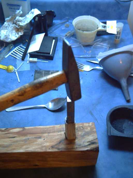
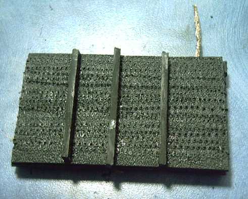
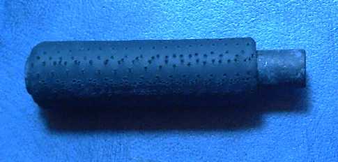
* This potassium chloride salt water electrolyte battery with mildly alkaline chemistry is safer than concentrated acid or alkali.

* The cells are about 2 volts instead of 1.2. It has at least as high an energy density as lithium ion, but the materials are dirt cheap.

* The electrode construction is a new type: square cylinder, "perforated hard plastic pocket electrodes". The encapsulated chemicals form a solid "briquette" inside, with a terminal wire sticking out the end. Perforating the plastic with a sewing machine or CNC laser cutter makes the battery "DIY" makeable.

* The positive electrode substance is new: nickel manganate. This works similar to regular nickel electrodes (nickel hydroxide), but it's insoluble at neutral pH for double voltage, and its low resistance gives heavy current capacity.

* Uses a new high voltage, high energy manganese negative electrode, whose reactions are made possible by an additive of 1% stibnite to stop hydrogen bubbling.

   Finally, I updated the battery making book on the web site about three times to try to keep up with the fast paced major developments.

   When John McCain was running for president of the USA, he suggested that $45,000,000 should be given to anyone who could come up with a better battery for electric cars. At last, I feel sure I'd have earned that money... if McCain had won the election... and followed through on it... and probably only if I was a US citizen... Instead, the day after the conference I scrounged some firewood from a tree cut down down the street - Oh boy, heat for next winter!
   The Ideawave Conference got local newspaper and TV coverage. The batteries got a couple of lines with my name in the paper, and in a breath in "From impromptu poetry to better batteries..." on the TV news.

   Along with the battery work, I was trying to set up a netbook computer with a new solid state drive and with Linux. A friend who was a Linux guru helped. Finally the computer simply refused to come on just when all was finished and it was finally reassembled with the new fast and silent "drive". It turned out (just before I was about to throw it in the garbage) that downloading and installing a new BIOS per a complex procedure fixed it. Everything took a lot of time that ate project time. I needed to use the netbook for some jobs and software, including to create new files for the PCB maker, who couldn't seem to read the files e-mailed from my Macintosh, and to upload the newsletters onto my other website with a new program.

   Almost the only non-battery R & D I did was to add a switch to an LED light fixture so it could be easily turned on and off if it was hung on a wall. There seems to be potential that wall mounted LED lights could replace many lamps as well as installed light fixtures, thus saving the table space occupied by the lamp.


   I went to a "VEVA" electric vehicles club meeting in Victoria on the evening of the 15th, the second one and now intended to be monthly. The instigator arrived on his electric bicycle. There's a web site: http://veva.ca/veva-islands .
   Here I found someone who had a good experience buying a Chevy Volt. No one badgered him and it arrived a couple of months early instead of late. I got a ride. It was certainly a luxury car - really quiet, smooth and with every conceivable appointment and more you've never thought of. Of course I still say they're making them that way to keep the price, over 40,000$, out of most peoples' reach, but it's nice you don't get hassled if you go to buy one. It was said General Electric has ordered 5000 of them - that can only be good!
   The "Seguay" was a no-show. Maybe next month? The "real" VEVA meeting in Vancouver the same night evidently showed an electric outboard boat motor made or converted by someone in North Vancouver.
   And my friend's i-MiEV did finally arrive this month with no further arguments or problems. It's a beauty, and if not cheap, it's at least substantially less costly than the Volt. Perhaps the zeal, or the grip, of those who want us to stay on oil forever is waning. He wants to show it at the March meeting. (Wednesday March 21st at Dairy Queen, 2350 Douglas Street, Victoria BC - "Driving, Riding, Testing & fun from 6:30 to 7:30. Meeting at 7pm to 7:30")
   When my new chemistry batteries are being mass produced (whenever that may be), it should start knocking around $10,000 off the price of electric cars versus using lithiums. (Boy could I use $10,000 'extra' dollars this year!)

   I did get a non-battery idea: to try to get the torque converter working on the dirt bike, using the rotors already made or making a similar pair. The bike, needing less torque than the car, would only need the magnetic impulse part of the converter, which seems to work great, and not the second mechanical assist part whose present construction is more questionable. It seems like a great interim project to prove out that part of the converter and note any improvements that might be made to it, in operating parameters or construction details.
   I wanted to rush in and try to get it working by month's end, before starting on my tax forms in March. But after weeks of fast paced battery progress, writing an up to the minute talk about it for Ideawave, and then actually attending the conference and speaking, there was hardly a clean dish in the house, the larder was bare, the place was a mess, and a break could surely only do me good. With only 3 days left in February, the converter would have to wait until later in March. But on the 29th I bought the additional parts I think I'll need - two choices of sprocket gear and some bearings.
   On the 29th also, the CNC conversion kit for the milling machine arrived, and I ordered plastic burning laser diodes to perforate battery electrodes automatically.


Magnetic Impulse Torque Converter Project

   An initial test at the start of the month showed the springs weren't returning the "hammer rotor" to center, and a quick adjustment didn't fix it. A couple of bolts were sticking out and hitting the chain. Then I got into the new chemistry batteries.
   Later I had an idea: I still had the dirt bike here, and with the torque wrench I measured how much torque it actually took at the motor shaft to move the bike, on level ground, and with small resistance to motion such as a bit of uphill grade or a rock. It all seemed to be under 10 foot pounds - mostly closer to 5 or even less. Since the chain is geared 4 to 1, that equates to 20 to 40 foot-pounds at the wheel. That's 1/3 of what the car needs. (It would be still less if the wheels weren't larger diameter.)
   As one might suspect from these figures, plus both the motor specs (approximate tho they are) and the ride last summer, the motor draws about 11 or 12 amps per foot-pound, hence the 80 amps it took to go upslope would have been only 6 or 7 foot-pounds - about 25 at the wheels. As I said at the time, it was as if the bike was stuck in 3rd gear.

   A key difference between the bike and the car is that the magnetic impulse of the torque converter seems able to put out about 8 or 10 foot-pounds as is, so it wouldn't need an additional 3-4x boost of a mechanical hammer part to roll the bike. I have the rotors and can get a fitting sprocket gear locally at Princess Auto, so it would be easy to rig up the torque converter on the bike, by making a longer shaft for the motor. With the variable advantage of up to 5 to 1, plus the 4 to 1 chain advantage, the magnetic part of the torque converter should do a nice job of running the bike while being very easy on the motor. In fact, the 4 to 1 ratio might be reduced to 3 to 1 for higher top speed.

   Applied directly to the Tercel car wheel, the converter would need something like 100 to 150 foot-pounds at its output; to the Sprint mechanism with reduction, 25 to 40; to the bike, somewhere between 5 and 15. Doing the bike shouldn't be a long project, and it seems like a good one for late March (after the Turquoise Energy Limited year-end tax return is done) - (a) just to get something that works after almost three years, and (b) to potentially learn more from before scaling up to cars.

   On the 29th I went out and bought a couple of sprocket gears, bearings, and a "1/2 link" for the bike chain, which it needed and would have had long ago if I'd known there was such a thing. The link even had a cotter pin so the chain could easily be attached to and removed from the bike.
   I got a 12 tooth gear (4.33 to 1), but I also found an "idler gear" complete with center bearing. If I can drill bolt holes through that, I can mount the output rotor with the copper wedge on it and things might be easier to assemble and more compact. It has 17 teeth (it was the smallest one for #40 chain), so the final drive ratio will be 3 to 1 instead of 4.33 to 1 -- If I use it I hope the torque converter can handle the somewhat higher than planned load.


LED Lighting Project

    What with hanging LED light fixtures from nails on the wall and plugging them in and unplugging them, the idea occurred that it would be nice to have a switch on the light. I had a rare visit from a cousin, who immediately got the idea that one could replace table lamps with wall-hanging LED lights, which wouldn't occupy table space. She seemed quite enthusiastic. I had been sort of figuring this myself, and by this time had several LED light fixtures on the walls, but I thought that others might not like the idea. Of course, one could make them all dim-off-bright "3 way" lights with 3 position switches, too.
   The next day I finally got around to putting a switch on one of the fixtures. I had been concerned that flipping the switch would cause the light to swivel back and forth, but then I got the idea to turn the switch sideways, so it goes in and out from the wall. The standard switch conventions now need an extension... is "off" push or pull? I made it "pull" because it's easier to push it on groping in the dark than to pull it.

   I also got a shipment of nice plastic 6" globe diffusers, and a few "plastic jar" diffusers, which are interchangeable with each other and with the glass ones. I like them better, especially for shipping if I do mail order.

   I finally got acceptance and instructions from Energy Star, but with all the battery work, and the unco-operative netbook computer, I didn't get around to even reading it.


Turquoise Battery Project

Shorter Version of long story

 A couple of days into February previous battery cell designs went by the wayside: I came up with a whole simpler way to make batteries: with perforated hard plastic pocket electrodes. These self contained, self supporting electrodes might be my best DIY battery making development.
   A problem is that normally everything has to be precisely fitted and crammed into place as the cell is closed, or the electrodes swell up and lose their conductivity when liquid is added. However, the fit of electrodes in self contained enclosures is of little import - tolerances within the battery can be quite sloppy and electrode sizes and shapes quite approximate. With perforated metal electrode enclosures, Edison even used round "pencil" tube positives and flat plate negatives.

Compacting electrode powders into a square perforated cylinder

   I thought the idea might well be impractical, but I did some footwork looking for ways and means. The essential DIY perforator for making thousands of tiny holes in rigid plastic sheets turned out to be a heavy duty sewing machine. Later, an idea from the Ideawave conference was that a CNC laser cutter could do the job better (more dense and better formed holes) and unattended for 'real' production, and I ordered laser diodes to mount on my own CNC drill-router - that'll be in fact cheaper than the used sewing machine was.
   Once the sheets are perforated, there seemed to be two possible layout options: perforated square cylinders, or encapsulated plates with perforated faces. For a while I was using 1/16" ABS plastic. 1/2" square cylinders worked but had a disappointingly high internal resistance, so I made some 1/4". Then I had better success with a 1/2" one, so the jury's still out which is better.
   Obviously thinner plastic would be better. When at length I obtained some .020" styrene it curled up in the oven, so it couldn't be formed into cylinders. I finally decided it was too soft, period.
   I ordered some gray .030" PVC near the end of the month. It turned out to be pretty stiff, a good hardness. The Singer 503 could punch the holes. So could the cheap machine, but only barely and slowly. And, it could easily be formed into a square tube in half a minute just by heating it with a heat gun - forget the oven. It's the keeper.
   The cylinders are so much easier to make than the better conducting plates that I think they're a keeper. (And in what other electrode can you pull the whole current collector out and replace it?) But so far, it looks like getting enough current to run an Electric Hubcap motor would mean having enough battery substance for a very long driving range. Hopefully this can be improved.

   The perforated pocket electrode idea goes back to the 1880s, but the material is changed from nickel plated steel to rigid ABS, PVC or styrene plastic.


First flat plate perforated plastic pocket electrode.
I glued ribs outside on both faces, fearing the center would bulge out too much.
For flooded cells gas needs a gap to bubble up though anyway.
This nickel plated current collector grill and leed was the last one before I found out they had to be zinc coated.

   With both layouts the essential point is to hold the electrode substance tightly compacted within the perforated "pocket" so it can't swell and lose conductivity. The flat plate with grill yielded substantially lower resistance and higher current capacity. (not surprising) However, the cylinders seem much simpler to do.
  
First pocket electrode battery with 1/2" square cylinder electrodes.
Case is sheet ABS fised with methylene chloride.

   For experimenting, pocket electrodes can be immersed, removed and swapped around, so any working electrode can be used to test multiple opposite experimental electrodes. For making batteries, as many pocket electrodes as desired can be assembled to create cells of any size.

   Before mid-month I (finally) realized that not only the electrode substance but the current collector has to have sufficient overvoltage not to bubble oxygen, chlorine, or hydrogen gas at the electrode charging voltage. Hydrogen generation by the negatrode collector grill has been the heretofore mysterious cause of all my frustration with cells being hard to charge and having unworkably high self discharge - it had little to do with the chemistries being tested except that they were mostly higher voltage, over a volt. The only negatrodes I made that really worked were one with nickel at -.5(?) volts... which is below hydrogen's voltage entirely, and a zinc sheet electrode... with the soldered leed out of the electrolyte. Finally I know what's going on.
   The simple solution seems to be to plate the negatrode current collector with zinc, or silver, or an alloy including one of them, which metals have sufficient overvoltage. The copper, nickel, steel, tin, carbon or grafpoxy collectors or coatings I tried all only work with lower voltage negatrodes - nickel, cadmium, metal hydride, or iron. Of course, I've mostly been trying to make highest voltage negatrodes, zinc or manganese, for best energy density.
   Zinc coated wire and grill can be purchased at agricultural supplies, tho the finest grill there was awfully coarse for a battery. I tried melting zinc (dry cell cases) in a stainless pot on a stove burner, and it worked. It seemed to be about 1/2 slag, yellowish zinc oxide, but there was a good pool of zinc too. The ends of the wire or grill can be dipped into that to coat them, probably with borax for flux.
   Zinc plated parts hasn't 100% solved self discharge problems, but the remnant may likely be explained by impure electrolyte, impure ingredients, or (tho unlikely) nitrate-nitrite reactions of the ABS plastic - the manganese is about the same as the zinc, which ought to stay charged. Or perhaps the zinc plating on the bolts I used doesn't have 100% coverage? (Yes, this did seem to be the problem.)

   These two solutions, perforated plastic pocket electrodes and zinc coated negatrode components, put the project on track for further developments. The manganese negatrodes with 1% stibnite to raise the hydrogen overvoltage finally started working well. In principle "NiMn" now looks like the singular chemistry of choice, probably better for most applications than NiFe, NiCd, NiZn or NiMH... or PbPb. It has high voltage and high conductivity without zinc's troublesome zincate ion, the most energy of all per kilogram, should have exceptionally long cycle life, and it's green and it's dirt cheap.

   I did a bit of testing of harder jewelry carving/casting waxes to make "graf-waxy" for the positrodes. Resistances were higher than for "grafpoxy" with the same amount of graphite by weight, but it got hard to work if I added more graphite powder. I ended up diluting it with parafin wax, which is much softer. More experiments will follow.

   At the same time as I conceived the new construction, I got the idea of using nickel manganate in addition to or in place of nickel hydroxide to improve conductivity of the positrode. Cell conductivity and hence amp capacity is substantially improved. A pretty small battery might start a car.
   I made some, and tried replacing the Ni(OH)2 entirely. It worked. The nickel might charge from NiMn2O4 [II] to, eg, Ni(OH)Mn2O4 [III] and or Ni(O)Mn2O4 [IV], similar to regular nickel oxyhydroxide reactions. In addition, it'll probably squeeze more out of the somewhat pricey nickel, discharging it readily almost to valence 2.0, whereas nickel oxyhydroxide ceases to provide much current when the valence drops below 2.25 and so it doesn't attain the theoretical amp-hours values. It was also likely to be solid both charged and discharged in neutral pH electrolyte. And in neutral pH, the voltage of nickel is almost a volt instead of half a volt, so altho the molecules weigh more, the energy density of the nickel itself is doubled, improving the watt-hours per dollar performance.
   I made a bit by converting some nickel oxide to nickel chloride and then adding potassium permanganate, but it was a smelly mess and tedious to make a small amount, and it was slow as the liquid had to be evaporated off. I made some more by mixing nickel oxide and manganese oxide and torching it to red hot with a swirljet propane torch. (Outside, in a stainless steel pot, with a respirator on.) As long as it has the 1 to 2 molecular ratio of Ni to Mn, as many oxygens as want to can attach themselves to the NiMn2Ox, in the flame and then in the cell.
   Its conductivity was better than the liquid-made batch, between that of MnO2 and Ni(OH)2 (which gave no reading at all). As made so far, it certainly won't replace graphite, but I doubt I've achieved the lowest resistance possible. Positrodes made late in the month from this and graphite powder seemed to perform much better than nickel hydroxide positives. So this substance looks like a keeper!

   I also studied the Pourbaix diagrams of the metallic elements of interest and came to the conclusion that the ideal pH would be in the range of 10 to 12.5, neither neutral (7) as I've been trying, nor solidly alkaline (14) as is commonly used. But then I started to realize that the hydroxide charging reactions turn the cells alkaline, probably to pH 14, regardless of what's used for electrolyte, just as lead-acid cells always return to being acid, pH 1, even after replacing the acid with neutral sodium sulfate. Starting with KCl salt, however, is safer than using caustic KOH -- the concentration of caustic OH- ions will remain low.
   But once I had this all worked out, the last cell of the month (with NiMn2O4 & Mn) seemed to stay pretty neutral, and seemed to work admirably. After adding Ca(OH)2, it appeared (as far as the pH test paper could be relied on), that the electrolyte pH was 7 or 8 on the positive side of the separator paper and about 10 to 12 on the minus. (And that's without even any special coatings on the separator.) This range seems just about ideal.
   I also found that the pH test strips I was using, with distinct colors for each pH, are inaccurate in the alkaline area, clearly indicating "13" in concentrated KOH, which is clearly 14. The other type I have is even worse, the alkaline colors all beng very similar (not to say indistinguishable) on the chart. I need to find something better before coming to exact conclusions about alkalinity from test results.

   On the 23rd I made a battery with all the features described above, and on the 24th, charging revealed that it worked - after 2 out of 3 negatrode leeds corroded off, fortunately leaving just the good one. That's the end of the "Short Version". The rest of this newsletter (2/3 of it) is a long, more or less a blow-by-blow, day-to-day diary written as I was doing the work. It's probably worth reading only for historical record or for a few "how-to" details if you actually want to make batteries.

Simple Homemade Battery Electrodes? - Evolution of a new design

   As I considered all the work to make each electrode and get it into a battery cell to test it, a simpler idea for test electrodes came to me on the 3rd, which was a convergence of several separate ideas I've had over the last couple of years, none of which quite had everything that was needed separately. This developed over a week or so into into a new, easier to do, DIY battery design. The sections below are pretty much a diary of the project. To cut to the chase, I suggest skipping to design 4.

Design 1 - simple perf tube test  electrodes (was a no-go)

* Take a piece of fat polyolefin heatshrink tubing [electronics parts store] and put lots of tiny holes in it (sewing machine with no thread)
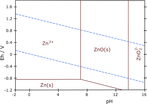
* take a carbon rod from a D cell (no grafpoxying to do)
* put the piece of heatshrink around it, leaving the top clear for a terminal post
* tighten a cable tie [electronics parts store, etc] around at the top end. Now it's a plastic 'pouch' with the rod in the middle.
* stuff in the powder(s). Tamp it in well with a pipe that just fits over the carbon rod, and just fits inside the heatshrink. K & S brass tubes [hobby shop] come in telescoping sizes in 1/32" increments, so a custom pipe can be made. The better you can cram the powder in short of ripping the heatshrink, the better the battery should work. (For my carbon rods and heatshrink, 3/8" and 13/32". I used a little rectangular plastic 'stick' the first time, but the compaction, and hence performance, was poor.)
* put a cable tie over the bottom end of the heatshrink - now the powder is enclosed, a plastic shelled "pocket electrode"
* take a heat gun to it to shrink the heatshrink (a half-assed job of further compacting the electrode)
* put two such electrodes into a jar of electrolyte and try them out, with or without painted separator paper and cellophane doping ideas. Theoretically they're self insulating, but there may be enough powder squeezes out the holes to short two together. If that proves to be the case, use separator paper between them: watercolor paper, coffee filter paper...

If you make a jig with a larger pipe to go around the heatshrink and hold it upright on the table, you can probably cram the powder in better with less risk of ripping the plastic, and both hands will be free to work. If the outside tube is square and the tamper can be made to fit... say a square piece of steel with a hole drilled for the carbon rod... the electrodes could pretty much fill the space in the case, and you could tamp with a hammer. (Say, I'm really starting to like this!)

   To try a new electrode idea, it would be simple to re-use the working opposite electrode. It didn't matter that the cells wouldn't have much current or amp-hours, only whether they basically worked and held charge. Then it would be seen whether it was worth doing a proper electrode and battery cell.
   The idea seemed promising enough to at least try out. The obvious choice was to make a zinc electrode, and try it first with nickel electrodes from the nickel iron cell. The mix was simple:

10g ZnO
.15g Sb2S3
.2g veegum (bentonite clay)

   Zinc should work without overvoltage raising... but better with it than without. First I crunched up some stibnite with a hammer on an anvil to make it as fine as possible, as I had noticed even the 'fine' powder did a lot of crunching when ground with mortar and pestle - it's too coarse. 
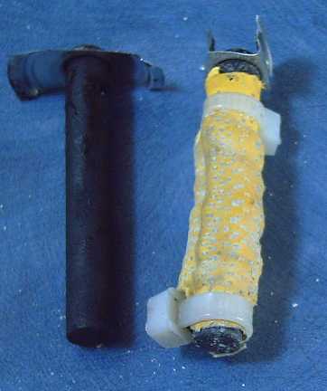
Veegum for glue. About 6 grams stuffed into the 'pouch', theoretically about 3-1/2 amp-hours worth. The nickel electrodes should be of similar capacity.
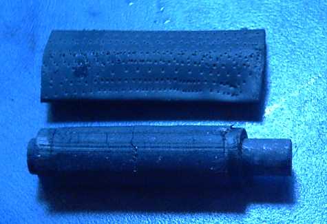
   Electrolyte pH, left over from the Mn electrode, was about 13. The nickel plating on the nickel electrodes showed some discoloration that might indicate they were starting to corrode in the lower pH electrolyte. The voltage started at about .45 - the zinc was entirely discharged as ZnO. I was eager to get it going, but the Alkaline Storage Batteries book says to leave zinc electrodes in the KOH for a day before charging, so the alkaline electrolyte can remove any zinc carbonate. The voltage was rising, and in a few hours it was around .8, so something did seem to be happening.

If the Pourbaix diagram is correct, at pH 13 instead of 14, the zinc should work without making the troublesome zincate ion. How many things have people tried to eliminate or reduce the effects of this ion, but no one thought just to lower the pH! On the other hand, the standard dry cell reaction Zn to ZnCl2 is -1.04 volts in neutral solution, which isn't the voltage shown on the Pourbaix. So the idea is suggested, but not proven, by the diagram indicating it.

   The zinc electrode was crap. It sort of charged - about like so many of my poorly performing electrodes. I don't think the powder was well enough compacted.  Later I uncovered two separate causes: first, the zinc oxide powder was yellowish gray. According to Wikipedia, that means it's not pure - it should be white. I had another bag, and this one was white. But I found the resistance was quite high even when well tamped down. I added graphite to the second attempt.

   But by late afternoon of that day (4th), I had not only ideas of how to improve this construction and make real batteries with it, but all the vital jigs and parts ready to go - even some more appropriate sewing machine needles.

Design 2 - "Real" Perf Heatshrink Cylindrical Pocket Electrodes (second no-go design)


Compacted zinc electrode on carbon rod, and perforated heatshrink.
Note ABS plastic "washers" at each end.


Heatshrink on and shrunk

   I replaced the cable ties with 1/8" thick ABS "washers" that fit tightly around the carbon rod. A brass tube with 1/64" wall thickness [K & S Brass, hobby shop] defined the outside shape of the electrode, and the washers fit just inside it. The brass tube fit upright in a hole in a piece of wood for a holding jig. The heatshrink, added later, fit just around the brass tube. I used 1/2" heatshrink, and "D" dry cell carbon rods, which are about 5/16" diameter. I thought "F" cell rods would be a nice length, but they're not as common.

   I used this same brass tube to melt through the ABS sheet to form the washers, heating the tube with a 1500W heat gun and pressing on the plastic until it melted its way through. (Drilling the 5/16" holes for the carbon rod dead center was a challenge, and there were more rejects than successes. Another jig or tool was required.)

   First the bottom 'washer' was pushed over the bottom of the carbon rod, then the carbon rod was pushed into the bottom of the brass tube. The top of the rod stuck out of the tube. The tube was held in the hole in the wood.
   A piece of the next size up of telescoping brass rod was placed over the upright tube, and a little of the electrode mix was dumped in through a funnel.
   This larger tube was pulled off and a pipe (perhaps made of smaller telescoping sizes of brass tube) was inserted into the upright tube. (I had a lathe and a piece of 1/4" brass NPT pipe. So I turned the outside down a bit until it fit well, and turned the end flat. This gave a nice solid pipe, and the inside hole was a good size.) The pipe was gently but firmly tapped with a hammer to compact the particles in the tube. (Being careful of the brittle carbon rod!)
   The process of pouring in powder and compacting it was repeated until there was maybe 3/4" of carbon rod left free at the top. Then a top washer was slipped on and pushed down.

   Now the perforated heatshrink was slipped over the bottom end of the tube, and the electrode was pushed out of the tube with the pipe, into the heatshrink. Then the heatshrink was heated to tighten it over the electrode.

   Presto! - I thought - one great Plastic Pocket Electrode!

   Well... that was the theory. The mix for the second electrode, just a day after the first, was 20g calcined zinc oxide (white - purer), .3g Sb2S3, .4g veegum, 7.5g graphite powder, and 1g dieselkleen. The graphite powder greatly improved the poor conductivity... for the initial test. I'm not sure why they didn't use it in the mix in Alkaline Storage Batteries except that the metal pocket electrodes were very thin, so all the zinc was very close to metal. Less than 1/3 of this mix fit in.
   It proved unexpectedly difficult to get the electrode to slide out of the brass tube. I don't know why I didn't think it would be, after mashing in the zinc mix with a hammer and punch. I could try putting in a piece of polyethylene to make it slippery. If that didn't work, I'd have to remake the tools so the heatshrink went inside the tube with the electrode while it was being compacted. That might come out easier... and hopefully the heatshrink wouldn't rip during the hammering.

   But I did eventually get the electrode out, then I shrunk the heatshrink tube around it. Then it went into the battery to sit overnight. It performed better than the first one... but not well. Since nickel-zinc in alkaline solution is a known, working chemie, the conclusion is the construction is at fault. [Note: It was actually the low hydrogen overvoltage of the carbon rod.] The main thing that could go wrong with the construction would probably be, as usual, insufficient compacting or failing to keep the electrode compacted once it's in the cell. It was supposed to keep itself compacted, but evidently the heatshrink can expand too easily for this. But the heatshrink is about the toughest stuff one could punch holes in with a sewing machine.

   It seemed as if the whole idea was a failure. How could it be redeemed? One way would be by finding a material that worked, that had the strength. But if it didn't shrink, how could it hold the electrode compacted?

Design 3 - "jammed-in" square heatshrink electrodes battery (not tried)

   There was another way: make the electrodes square, and make battery cases that were an exact fit, with no room to expand except by bulging the slightly flexible ABS sides. A square cross section electrode would be better anyway - less liquid and better conductivity in the battery.

 Electrodes would be placed checkerboard style. Each electrode has its post sticking up through the top of the battery, and all connections are made externally, with metal clamps on the exposed top section of each carbon rod.

   It would need square tubes and jigs. Doable, but the jigs would take more doing. It would be better and easier to have rigid plastic tubes, and to compact the electrodes within the actual tube. Where could I get square ABS tubes, and how could they be perforated?

   At this point, the idea had moved away from a simple way to make test electrodes, to another full-fledged battery design. But it seemed like a good one - instead of two flat electrodes defining the size and shape of a small cell, a checkerboard of any number of electrodes could be accommodated to make a battery cell of any desired size and capacity. It made sense.
   Then, perhaps the terminal should then be a grafpoxied fat copper wire, with the top end bare for the external connection? That had the disadvantage of being thinner with less surface area to interface to the electrode substance, but the advantage of eliminating the arbitrary height constraint imposed by the D cell carbon rods. Taller, thinner electrodes would be the result. If they were, say 10mm square by 6cm tall, each one would have about 1/2 the capacity of the flat electrode design. So a cell with 16 of them, just 2" square by 3" tall, would have four times the capacity of the flat "cassette tape" size battery. I decided to try common #14 AWG house wire and see how that held out during assembly, ie, whether it would flex and crack the grafpoxy. If it did, I'd go to #12 or #10, tho such fat wires would surely not be required by the currents. I also thought I'd try dipping the wire in graphite when the epoxy was still tacky. The powder that only sort-of glued on would give the wire a matt conductive outer skin which might connect better with the surrounding electrode mix.
   It also needed square tubes for the jig, sized to match some common heatshrink tube size. Optimally, one could use rigid perforated plastic square tubes. I fear these would need elaborate equipment to make.

Design 4 - Perforated ABS Plastic Square Cylinder Pocket Cells (a go, after a couple of tries!)

   A rigid but thin-walled perforated plastic tube would hold the electrode compacted. The only special compaction tool would be a punch with the hole for the carbon rod. But perforations?... I could imagine setting up the CNC drill-router and leaving it to drill tiny holes for hours, but the drill bits would probably break before it got very far.
   But at this point, I had another idea, in lieu of such square plastic tubes and such perforating equipment. My sewing machine couldn't punch through, eg, the 1/16" ABS plastic sheet - but maybe there was a more "industrial" one that could, if armed with a heavy punching needle? (And if there was any thinner ABS to be had, that would be an asset.) ABS can be glued! If one could perforate a flat sheet of ABS, many options would be open, such as sheet electrodes of any size with posts glued from top to bottom, at the ends and then about every 10 or 15mm, to form a series of narrow vertical column electrodes, eg, 6mm x 15mm cross section. This would be rather similar in form to metal pocket electrodes, with the top and bottom also glued shut. Each slot would only be able to expand to the extent of bulging the plastic a bit. A grafpoxied wire would stick up from each slot for external connection.
   The ideas flowed fast and furious... perhaps my CNC drill-router could be armed instead with that leather punch needle? It would be awfully slow, but it might - probably - work. Maybe it could hold several needles at once?
   One could perhaps take thin wall round tube, heat it in the oven, and form it square, but the punch has to fit through, tightly, which would be close tolerance, hard to get with forming. It's probably easier to glue flat sheets. So it now seemed to boil down to what material I could find: suitable square plastic tube, thinner ABS sheet, or the 1/16" ABS sheet that I already had.
   A couple of hours on the web searching for square plastic tube yielded no better results than when I'd searched before (looking for somewhat larger sizes for battery cases).

   Another idea... one could heat 1/16" perforated flat sheets in the oven, and try and form them square, around the square punch to get the size. The fourth corner would need gluing - and might break open. I decided to try this anyway, with an unperforated sheet. I set the oven to 325ºF for 15 minutes. I put the 1/2" square punch in too, so it wouldn't quickly cool and harden the plastic. (I soon stopped heating the bar, and turned the oven up to 350ºF for about 5 minutes for each piece - they shrink less with a shorter heating period.)
   The plastic shrank in the oven (and thickened, perhaps proportionately) and only covered 3 sides of the square. But it looked Promising. It seemed to have the strength to hold an electrode together without much swelling.
   Then I had the thought that one could lap the plastic over itself at the seam. That would be stronger, and even a doubled side would have less excess plastic than flat sheets with 3/16" or 1/4" dividers glued in. I cut a bigger piece, 3-1/4" to go around the 1/2" square with (I hoped) a lap. Then I cut a channel from a piece of steel. I pushed the soft plastic into the channel with the square bar. This did a neater job, but the channel was a bit wide and the sides were rounded. For the next try, I cut a custom channel in a piece of dogwood. The fit was good, and having the bar inside while forming the tube ensured it couldn't end up undersize.
   Thus the results were quite satisfactory. The lap meant it didn't matter whether the edges were square, which of course they couldn't be with uneven shrinkage in the oven. The finished ends could be cut or sanded square. I could already see ways to improve the bending tools for more even bends at all corners. And ABS comes in black (for negatrodes) and white (positrodes). But fine tuning could come later - the main objective was attained.

   The remaining question then was whether it would be practical to punch the multitude of tiny holes - preferably in the flat sheet before forming it into a tube - assuming they wouldn't close up when heated. If that could be done, it looked like I could soon have real, working electrodes... followed by real, working batteries. Better chemistry was merely a bonus!
   When I went there, the sewing machine shops claimed probably no sewing machine could do it. I started getting discouraged, and thinking I'd have to build a whole complex machine for the job. But the answer, suggested by the owner of Victoria Clay Arts pottery supply store, did turn out to be to get an "industrial" or upholstery sewing machine. He said he had worked with such machines doing upholstery in the past and they went through several layers of tough stuff. He said to stop by Tommy's Auto Upholstery. A worker there demonstrated that his heavy sewing machine could punch the plastic easily - so much for the 'expertise' of the sewing machine shops!
   I found a heavier household machine that was just adequate on UsedVictoria.com for 200$. The holes were very tiny, much smaller than those of the upholstery machine. In fact, they pretty much closed right up again when the plastic was heated in the oven. Obviously he had bigger needles. I was using leather punching needles. I went back the next day (7th) to see what type he had - and if they'd fit my machine.
   They were upholstery needles, and wouldn't fit a domestic machine. I went back to a sewing machine store to see what else might be available. There were a couple of slightly fatter needles. I bought the largest and found my machine wouldn't push them through. I looked again at my leather punching needles package and found it was an "assortment". I had been using the smaller sizes. I took the largest, ("100/16" - 1.00mm diameter) sharpened it on a diamond wheel, and tried it. The holes stayed open after forming - it worked!

   The grafpoxied wires turned out to be an unexpected issue: the first batch had too high a contact resistance. It was one thing to make a grafpoxy coated grill with a lot of fine surface area to connect to, but another to use a single wire with a limited surface. In the first test electrode, I pulled out the wire with pliers, and pounded in a fat piece of bare #8 nickel-brass wire to replace it. Because it was a negative electrode and being tested in alkaline electrolyte, I could get away with bare wire.
   For the second batch, I added enough graphite to make the mix 7 to 5 by weight. Then I had to add about 15-20% toluene to make iit thin enough to work with. And I made a few from a larger gauge of wire, #10, just for its greater surface area. The resistance dropped from low kilohms to mid tens of ohms.
   To get lower might take carbon rods from dry cells. That would be a last resort, but it would guarantee the design was viable if the grafpoxied wires just didn't work out. It's also possible for negative electrodes that bare wire would suffice, depending on alkalinity.


Some effective dimensions:

Changhong nickel plated steel pocket electrode (NPSPE): 2 x 55 x 65 mm = 7.15 cc
Perforated plastic pocket electrode (PPPE): 12 x 12 x 50 mm (inside) = 7.2 cc
My original flat electrodes: 4mm x 1.5" x 3" = 11.6 cc (just 1.6 * more than a single pocket electrode)

max distance material to conductor:
NPSPE: 1 mm
PPPE: ~6 mm

Admittedly the steel pocket electrode should have a much better current rate than the plastic. But nickel-iron has a slow rate - the iron is at fault. Nickel-zinc and nickel-hydride are substantially better, but the nickel is also slow. I think nickel manganate, with either zinc or manganese negatrodes, will make up the difference; hopefully more. If not... add more graphite. This is DIY, after all - "good enough and doable" is better than "ultimate but too hard"!
   I've already found that it's pretty much impossible to put a grill inside an electrode like this - it just gets munched up during compaction. Another rather appealing option would be to have four grafpoxied wires, one in each corner, but examined carefully that's only a small improvement. Electrically better but not quite as easy physically: four wires, about half way from the center to each corner. This would cut the maximum distance to about 3mm, and four times as much of the material would be within 1mm of a wire.
   The single wire is certainly simplest, and extra graphite powder probably weighs less than extra copper wires.

   For the first electrode I used up the rest of the zinc oxide mixed for the second heatshrink attempt. Even with the bare wire, it proved unexpectedly slow, even for being a very thick electrode. I could have added more graphite to the zinc - would that have done it? Why did it need any at all? I poured out the electrolyte (still reading pH 13 instead of 14, but the water looked clear - no more purple color) and put in fresh KOH and a bit of KMnO4. The water turned green - manganate, Mn2O4! That would probably turn purple again on charging.
   The fresh electrolyte did seem to make some difference, but not the difference. 100 times better conductivity would have suited me fine. Would it get better as it charged the ZnO to Zn metal? Only if enough current would go in to charge it!

   Hmm... this time, the mix was well compacted, and could hardly have swelled much trapped within the ABS enclosure. The replacement bare wire was a good short circuit. Although it hadn't been compacted with the electrode, it had taken a bit of force to pound it in. What then was the problem?

   Finally I decided it was a combination of everything. First there weren't enough tiny holes - the electrolyte ions have too hard a time getting in and out. The commercial iron pocket electrodes have much denser hole spacing, and the metal is thin, maybe .01 to .015". The plastic is .063" thick, and the fewer holes tend to close up considerably - around the needle, and more when the plastic is heated. (This was soon improved with a fatter needle.)
   The second aspect to this is that a 12mm electrode is really thick, regardless of holes, the ions have a long way to go.
   The third main thing is the distance the electrons have to travel through semiconducting stuff before they reach the wire. 6mm, with more and more of the substance as distance increases, is a long way compared to 1.5mm max for a grill 1/2 way through a 3mm thick plate electrode, making the resistance high.

   I decided to try the manganese flat electrode with a nickel coated copper grill made earlier, and encase it as a pocket electrode with perforated front and back faces. I punched quite a lot of holes, and since I wasn't heating the flat plastic, they wouldn't tend to close up in the oven. The difference was immediately apparent: when a 100mA charge was connected, the voltage only rose 50mV, making total internal resistance .5Ω instead of several ohms. Presumably - and hopefully - that would drop as the electrode charged. (How many time have I expected that and got nothing?)
   The cell with this electrode had the usual high self discharge. It worked great with the Mn(OH)2 to Mn2O3 reaction at -.25 volts (cell total ~.75 volts), and discharged fine at over 100mA for almost 18 hours - well over 2 amp hours of juice. (It would thus have been over 4 AH, and of course over a volt higher, with the right reaction.)

   But was the tube idea dead? I decided to try making many more holes in another, thinner, tube electrode, 3/8" square, still with the 1/16" ABS, and see what improvement there was. If the first ones had a zillion holes, the next sheet had 5-8 zillion. I found I couldn't set the machine to do them too finely spaced, or each one pushed the last one closed. But I could suck and blow air through it much more easily than previous attempts.

   So the next electrode had lots of holes, and it was formed around a 3/8" square steel rod instead of 1/2" - 9.5mm square instead of 12.7. This should hit the problem from all angles. It would also take almost twice as many such electrodes to make a battery cell of a given capacity.
   Then I remembered I'd have to drill a long hole through a 3/8" steel punch, and decided to try 1/2" again but with the more, bigger holes -- and with a zinc coated leed, the need for which had just been recognized. I decided to try manganese again, and I used a zinc finish machine screw, #10-24 x 4" long. Instead of compacting around the bolt, I compacted without it and glued the bottom on. I got in about 18 grams of the mix, which would have included at least 12g of MnO2, theoretically 7 or 8 amp-hours worth. Then I pounded the bolt in with a hammer. The plastic split open towards the bottom - maybe that wasn't the best idea - but it might work with a zinced nail! I patched it by gluing in little bits of plastic.

   Initially it looked like the resistance was 3 or 4 ohms. The simplest DIY fix might just be to put in lots of electrodes in parallel. 6 * 6 electrodes, 18 of each in a checkerboard pattern, would bring it closer to .15 Ω. That would also be well over 100 amp-hours and, at 2 volts, 200 watt-hours. It would take a lot of cells to get to 150 amps capacity at 36 volts, like, 15 in parallel * 18 in series = 270 (almost 10,000 electrodes to make - ouch!), but at that point, it might be around 50,000 KWH. That's over twice what most well batteried EV's have.

   Then I made a complete cell. For the positive (the usual nickel oxyhydroxide, from monel) I used a grafpoxied wire. The conductivity was awful. The grafpoxy had low enough resistance for a grill will a lot of surface area to conduct through, but not enough for a single wire through a cylinder.
   One alternative would be to use carbon rods - only F cell rods (from lantern batteries) were long enough.
   The other was to hope the nickel manganate could be used in place of the graphite, "nimanga-poxy", and had substantially better conductivity. After all, it was originally for the reputed high conductivity that I was making the nickel manganate.

   If the square pockets are to be used to make cells, the conductivity was now the thing to focus on. It appeared to be the last major problem. Trying to compact around a conductive grill in the cylinder would be problematic. More graphite could help to an extent, but it's probably not enough. The thinner plastic, when it arrived, would put the electrodes .086" closer together.

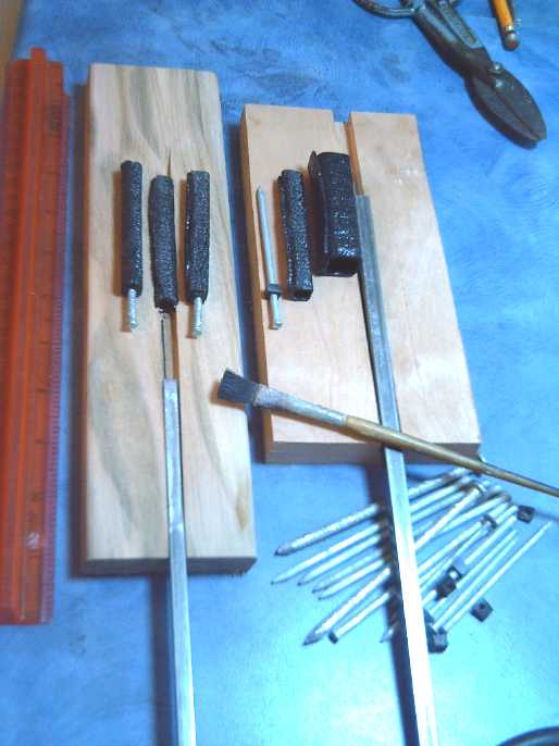
   After thinking about a few ideas, I started to realize that 1/2" square is probably just too fat. It's 6mm from the wire to the corners, where other alkaline electrodes are 1mm or less from any point to a current collector. 1/4" square electrodes would have four electrodes where one 1/2" one is. And they would be only 3mm to the corners (2mm with a fat center conductor), and there'd be 4 wires in place of one. That's a pretty small size to fill by hand, but undoubtedly more in line with the electrochemical requirements. The big challenge then is to find ways and means to make it very fast and easy to make each individual small electrode. (How do those cigarette roller/stuffer things work?)
   I bought 1/4" and 5/16" square steel rod to try. I decided to go with 1/4" first - given the results with the 1/2" size, the higher the conductivity gain the better. I made a channel to fold the plastic into, and then, after perforating and forming four electrode tubes, made a jig where the electrode fits in sideways, the powder is dumped or brushed into a slot, and the 1/4" square punch pushes the powder across the slot and into the electrode. Then it can be tamped to compact it.
   I ground down the end of the 1/4" square rod a bit so that it fit easily into the electrode pocket formed around the full dimension.

   The very next day I inquired about my order and got the .020" styrene plastic - the store hadn't ordered it for me because it was in stock all along. Having just made the jigs for the .063" and not even finished an electrode, I now made new ones for the .020". This turned into a disappointment as the thin plastic curled up in the oven and couldn't be made into cylinders. Later I decided it was too soft anyway - not much better than the heatshrink - and ordered a sheet of .030" PVC.
   When this arrived on the 23rd, I made 8 electrode cylinders successfully with it. It perforated okay, was tough (much tougher than the styrene), and it could be formed after simply heating it with a heat gun for 20 or 30 seconds.
   The electrodes and the cell as a whole seemed to work acceptably, but the methylene chloride didn't glue the PVC and conductivity dropped overnight - the electrodes probably swelled up by spreading the unglued seams. (PVC probably needs MEK for glue.) The story is continued under the "Nickel Manganate" subheading below, as the postrodes used that substance.

   To recap then, the idea morfed from a quick way to make a test electrode into a new and evidently superior (at least for DIY construction) way to make batteries. There were were significant challenges and concepts to making this construction work. At first glance, it seemed it would be too difficult, as the materials didn't seem to be available. The conductivity of the positive electrodes still needs work, but it would seem to be achievable:

a. Using rigid, glueable, and non-brittle plastic for the outside, and making square electrodes. The overlapped seam also was an important idea. Square .063" ABS (acrylonitrile butadiene styrene - the rubbery butyl is what makes it a bit soft) or the .030" PVC both flex just enough not to crack under pounding and pressure, which acrylic plastic or molded epoxy would probably do. And they are rigid enough to hold the electrode compacted in a square, which the heatshrink and the softer styrene wouldn't do. Square electrodes also occupy most of the space in the cell, where round ones waste space with the weight of extra water filling it. (Obviously, the .030" saves considerable space over the .063", too.)

b. Forming square ABS or PVC plastic tubes in the oven or with a heat gun. I couldn't find even close to suitable square plastic tubes for sale. But I found out a few months ago that ABS plastic went quite limp if heated hot enough in an oven (eg, 325-350ºF, hotter than I'd been trying previously), allowing it to be easily formed. (Even if I had found square tubes, they couldn't easily have been perforated.) I made a little jig and formed some tubes to prove the concept. On the second one it occurred to me to leave extra material and overlap the join, solving the problem of getting a solid join that wouldn't be prone to breaking open with the necessary pounding. The overlapped join is glued with methylene chloride when the bottom square is also glued in. The fact that one side sticks out farther than it otherwise needs to is a small price to pay for simple doability.

c. Using a wire as a terminal and current collector - a simple zinc coated nail or threaded rod for the negatrode, and a grafpoxy or nickel-manganate-epoxy wire for the positive. This is simple, better and easier to connect to than the carbon rods used in the first couple of tests. Probably the positives will put together the idea of grafpoxy with lower resistance nickel manganate replacing [some of] the graphite. The odds of successfully coating and working with a single wire and ending up with no gaps in the epoxy coating are excellent - unlike for a whole brittle grill with attached terminal wire.

d. How to perforate the plastic was the last big puzzle. If I couldn't figure out a way, everything else was in vain. Hundreds or thousands of tiny holes had to be easy to make - sitting there with a drill and a tiny drill bit would have been impractical, almost even for one electrode. Perforating the heatshrink tube was easy with a sewing machine, but it would hardly dent the ABS. As related above, I did get a machine and needle combo that worked, if only just. (Singer 503, 100/16 leather needle, sharpened.) The .030" PVC plastic was easier, and the cheap sewing machine would - just - go through it too. Bigger upholstery sewing machines are available.

CNC Laser Cutter to cut and perforate electrode plastic shells?

   At Ideawave, "Victoria Makerspace" showed (in a photo) their CNC laser cutter, and I got the idea that the plastic might be perforated with such a machine, as well as cut to exact size. That could perhaps make well sized, more closely and evenly spaced holes - better product than the sewing machine... and do it unattended, which would be fabulous. The main production question would probably be not whether, but how fast, it could do them.
  The main other practicality question would be whether it was affordable. I saw a "make a 50 $ laser cutter" on the web, using stepper motors from 2 old flatbed scanners, but I'm not sure I'm into it. Laser safety issues were raised in a number of the comments. [http://www.instructables.com/id/Laser-cutter-start-slicing-stuff-for-under-50-dol/?ALLSTEPS] On the other hand, I already have the CNC drill/router and (CNC to be) milling machine - an appropriate laser mounted on either one of them would cut. So, what is an appropriate laser, and how much does it cost? The one in the article was only enough for cutting black paper, not rigid .030" gray plastic. A commenter suggested 1 to 2 watts for 1/8" plastic.
   On the 29th I found various laser diodes on e-bay. (where a search for them just the day before had returned "no results"!) I bid on a pair of one watt infra-red ones that looked about right and got them for 31 $. It even showed a couple of holes the seller had burned in gray plastic with one. It could simply be held in the drill chuck, and could be powered and switched (I'm sure) in place of the compressed air valve solenoid.

Negatrode zinc plated current collector coating eliminates [most of the] self discharge problems - other causes of self discharge

   I read about an alloy of CuSnZn 55:25:20% called 'optalloy' or 'white bronze' that "behaves as a noble metal" and might not corrode. I thought this might be worth checking out as a better conducting alternative to grafpoxying wires and grills, but it turned out  it was only used in zinc negative sides. There it didn't corrode, but the paper mentioned it had a higher hydrogen overvoltage than other metals. (Graphite was chosen for the positives, as I have done.) Other statements of the composition of white bronze or optalloy were:

Top-layer composition: 55% Cu; 25-30% Sn; 15-20% Zn
Alloy Composition: Copper 54 to 65%, Tin 25 to 40%, Zinc 6 to 10%

   It still sounded potentially useful for reducing hydrogen generation... Then I began to realize that my problem with all my higher voltage negative electrodes bubbling was probably exactly that: the current collector had a lower hydrogen overvoltage than the voltage of the active chemical. It's probably been the current collectors that have been bubbling all along, rather than the electrode chemical!
   After all, what were my two most successful cells? The vanadium-nickel cell, and the nickel-zinc cell with the zinc metal sheet. Nickel as an alkaline negative is only -.72 volts -- lower than hydrogen voltage (-.833) regardless of overvoltage raising additives. The zinc sheet had no other metal in contact with the electrolyte: the soldered connection wire was on the top corner, and the corner was bent up to be out of the electrolyte. When I replaced the zinc sheet with a "real" zinc powder compressed electrode, the self discharge started happening as usual.
   I looked again at zinc electrodes in Alkaline Storage Batteries. Sure enough, where Edison used iron, nickel or anything for iron electrodes (-.93 volts and they bubble hydrogen easily), for zinc electrodes zinc or silver metal was used, with a welded silver leed wire. If the reason had been given, I'd have had this figured out long ago. (Instead I thought it had to do with them being silver-zinc batteries.)

   Making the alloy could perhaps consist of melting brass and adding tin to it. (One can melt tin on the kitchen stove and gradually melt brass into it. This would only work until the alloy had enough copper that its melting temperature reached the stove temperature, then it would solidify or at least stop melting more brass. I wonder what percentage of copper that would occur at?)
   Another thought would be to solder a brass wire with tin solder, flick off as much of the tin as possible, then heat it with a torch, to get a 'white bronzeish' surface alloy - the surface is what counts.

   I found an interesting article on stovetop zinc-aluminum metalcasting which may come in handy for such things as this: www.gizmology.net/stovetop.htm

On the 12th, I took some tin-silver solder and a small sheet of zinc (from a dry cell) and melted some zinc into the solder with a soldering iron with an 800 degree tip, so presumably I had tin-zinc solder (the silver is at most only ~3% of the tin). I estimate it had at least 10% zinc, possibly 20% or more. Zinc should have the best overvoltage. Tin alone (as shown in the Iranian research paper) was crap.
   I worked this along a copper wire with some plumbing flux until it was completely coated. The wire would be the current collector for the second zinc square cylinder electrode, which would have more, bigger holes than the first one, which would show how much difference improved electrolyte access made. The single job with the paste flux ruined my good soldering iron tip!

   Then I decided there might not be enough zinc in it, so I decided to melt some zinc in a pot on the stovetop and dipped the wire in it - galvanize it. I also considered that, assuming the manganese worked, its voltage was higher than that of zinc, so a pure zinc coating shouldn't corrode as long as the battery wasn't almost completely drained. Then I realized I could just buy long thin galvanized or zinc coated bolts - or even galvanized nails. Say, something that would actually be easy, off the shelf, for a change!

   I made a 1/2" square cylinder manganese negatrode with a zinc bolt for the current collector and stuffed it into the nickel-iron cell with a couple of nickelpositrode plates. The main problem seemed to be solved, but it still had discharge, which got gradually worse. Finally I took it apart. The corner had burst from excessive compacting, and I had wrapped it up with (insulated) wire. I now wrapped a separator paper around it. That seemed to mostly solve the problem: it would seem enough manganese and graphite had come out that it had started touching the nickel plated positrode, something of a short circuit.

   There's other reasons for self discharge, of course. I found this:

"
Impurities in the electrolyte, usually leached out of the positive electrode, can be a significant source of self-discharge.
 The most important of these is nitrate, which participates in a nitrate-nitrite shuttle mechanism between the positive and
 negative electrodes that can produce very high self-discharge rates in cells whose positive has not been carefully prepared.
"

   Evidently the nitrate-nitrite shuttle can self discharge a cell fairly quickly. It was originally identified when using polyamide as a separator material caused the problem.
   One advantage of flooded cells is that the electrolyte can be changed if it's causing a problem -- and if it's recognized that it could be the source of the problem, and that changing it could fix it.
   And, of course, if the new electrolyte is purer than the old... say, could my 50 pound bag of fertilizer grade KOH (it was all I could get) possibly be less than pure? What farmer would care if his 0-53-0 fertilizer was 2-50-1 with a bit of nitrate? I bet that accounts for the last remnant of the self discharge! So, that's enough of using the positrodes in the old NiFe cell and that nasty KOH electrolyte - I'll have to go with everything new and the "USP pure" KCl salt from the drug store from now on.

   But I'm not wholly convinced... another possibility is just that the zinc plating on the bolts I used isn't 100% coverage. If any little spots are unplated or if any plating got scraped off as I pounded or screwed them in, well, 2% unplated means at least 2% remaining self-discharge. Come to think of it, those bolts were both used once. It's entirely possible that tighening nuts on them would scrape off some of the coating. I got some zinc coated wire at Borden Mercantile (agricultural supply store) and will try using that - and plating the ends of the wire too, by dipping them with borax flux into molten zinc on the stove.

   Or, silver also works. A few years ago I made some 88-10-2 tin-silver-copper solder. To digress a bit, I was trying to make a stronger soft solder, but it doesn't work. I saw there's some with bismuth that was considerably stronger (3x?), but I can't remember the other metal, and it was still way below the strength of hard solder.
   I found the two batches I made, but they both say 4.7% silver, so evidently I neglected to re-label the strengthened batch. I'll take a guess. 4.7% silver might be enough anyway, tho tin alone doesn't work. I also have some tin-indium solder (low melting point)... I wonder if that would work? Or tin-lead? (Wouldn't it be just too simple if ordinary solder works!?!)

Graf-Waxy?

I got some purple carving wax - much harder than parafin wax and "sticky" when hot - on the 22nd, and tried melting it and mixing it with graphite.

8g wax, 8g graphite: workable, sticky, hard to scrape off, but x10000's of Ω
8g wax, 12g graphite: thicker and harder to work with, less sticky, around 4000 Ω
8g wax, 16g graphite: thick, hard to work with, and flaked off the copper wire easily, x100's of Ω
8g wax, 2g parafin wax, 16g graphite: thinner and easier to work with, x100's of ohms.

(Quantities shown don't consider the amounts lost in coating each test wire.)

   The grafpoxy at 1g to 1g has lower resistance, eg under 200 Ω, and is workable, so so far it appears  to be the choice. Of course, the resistance measured is contact resistance with the meter probe. The electrode contacts closely all over the wire, so there's a lot of resistances in parallel for a (hopefully) very low overall resistance. It might be worth trying out the fourth wire and seeing what change it has on the internal resistance of a cell overall. Thinner wax is more workable and a thinner coating should have lower resistance, but I wouldn't try thinning hot wax with a flammable solvent. Mixing in parafin wax seemed to work well.
   I also got "dap wax", which is brittle but feels as hard as plastic. Also sticky when hot, it's used to "glue" rocks, etc, onto "dap sticks" to work with the rock without getting your hands too close to the machinery. I have yet to try it.

   "Grafwax" does work, and unlike grafpoxy, which is useless once it's set, wax can be melted over and over again whenever it's needed. I'll be running more experiments to see if really good conductivity, hardness and coating characteristics can be obtained from any type or mix of wax.

Another Better Chemistry - or a conductivity additive? - Nickel [per]manganate Positrode

   With MnO2 and NiOOH mixtures both being common in alkaline batteries, I started to wonder about complexes of these chemicals. One that might be formed was nickel manganate or permanganate.
   On the web I gleaned that nickel manganate has low resistivity, owing to its 'spinel structure', and might be interesting just for that reason. Some of that in the nickel electrode could make for higher currents than simple NiOOH.

   I say info "gleaned" because there seems to be little of it on these substances, at least on the web. They aren't even mentioned in Wikipedia.

Web Gleanings:
  "Nickel manganate spinels NiMn2O4 are of special interest due to their low resistivity" -- This was my initial interest.

  "Nickel manganate was obtained by precipitation using solutions of sodium manganate and nickel chloride."

  "of nickel manganate NiMn2O4 obtained from nickel permanganate precursor" -- this was the most promising sounding prospect

(evidently this reaction is "adabiatic", that is, there's no heating or cooling effect going from nickel permanganate to nickel manganate or vise versa.)

"All permanganates except silver permanganate are soluble in water." (This is an interesting statement as common potassium permanganate is only very slightly soluble. I suspect the same may be true of the nickel...)

"Ni(MnO4)2→ [NiMn2] + 1.502" (If that last, unexplained, figure is a reaction voltage, that'd be some cell: +1.502 from the positrode and -1.56 from a manganese negative is 3.08 volts! However, that reaction was for thermal decomposition. I'm reading about +.65 from the pourbaix showing Mn2O4.)

   The simple way to get there might be to put some nickel chloride in the electrode along with the KMnO4, expecting it to become Ni(MnO4)2 'precursor'... and hope for the best. Nickel chloride should be easy enough to make: NiO + 2 HCl -> NiCl2 + H2O.

   Then in the electrode we'd have:
NiCl2 + 2 KMnO4 -> Ni(MnO4)2 + 2 KCl (all soluble except _probably_ the  nickel permanganate)
   The first is the desired product, the second is just more KCl electrolyte. The next step is more suspect:
Ni(MnO4)2 -> NiMn2O4 + 2 O2
   If the reaction happened as part of cell discharge, balanced by the negatrode, it should be:
Ni(MnO4)2 + 4 H2O + 8 e- -> NiMn2O4 + 8 OH-

   If it works this way, and if the reaction is reversible and a good voltage, this is suddenly very exciting electrochemistry: There are three metal cations per molecule, but each reaction creates eight OH- ions and moves eight electrons, instead of one. That would give substantially more amp-hours per kilogram than the usual nickel reaction, and using 1/3 of the nickel (hence lower cost - manganese is cheap). It would be on a par with the perchlorate idea that I didn't get going, potentially yielding cells of well over 200 watt-hours per kilogram.

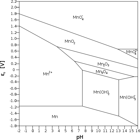
   Referring to the Mn Pourbaix diagram, it appears that the manganate ion will only form at pH 13 or above, but at about +.65 volts, which is 30% higher energy than the .5 volts of the NiOOH reaction on top of the higher amp-hours, and probably higher maximum amps capacity owing to lower internal resistance with the manganate spinel structure.
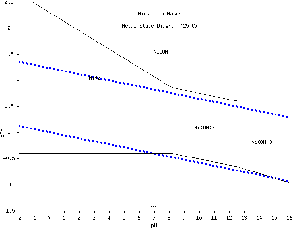
   But the Pourbaix diagrams are for non-complexing chemistries. It may be that nickel manganate and or permanganate are solid (insoluble), perhaps forming at a somewhat lower pH, and a different voltage if so - maybe .7 to .8, which sounds ideal if it doesn't just make oxygen gas on charging.


   On the other hand, the reaction voltage of nickel is lower (both in alkaline and salty solution), so the nickel might just attach an OH- to charge to valence 3:
 NiMn2O4 + OH-  <=>  Ni(OH)Mn2O4 + e- [+.95 V at neutral pH; +.49 V in alkali].

   On consideration, this or something akin seems more likely. The main differences then would be the high conductivity of nickel manganate compared to nickel hydroxide, allowing higher current flow, and that nickel manganate and the charged coumpounds are (seem to be) insoluble at neutral pH where the reaction voltage is around +.95, rather than the usual +.5 in alkali.
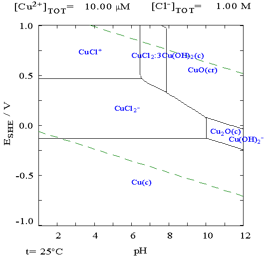
   More subtly, the nickel would retain its conductivity until it was completely charged and discharged, so the valence would go from 2.0 to 3.0 instead of only from about 2.25 to 3.0, a 33% increase in energy. Then, as is common in the presence of manganese compounds, there's the likelihood that the nickel will charge to mixed valence between 3 and 4. The second step might be along the lines of:
 Ni(OH)Mn2O4 + OH-  <=>  Ni(O)Mn2O4 + HOH + e- .
   In practice again, this usually goes from 2.25 to around 3.5 or 3.75 with nickel hydroxide, and again this should work right down to 2.0 with the manganate, so 2.0-3.75 versus 2.25-3.75 gives 16% more energy. If this is what happens, it would be headed for squeezing .5 AH/g and 500 WH/Kg from the nickel in salty electrolyte, but the nickel is more diluted.
   Calculating with the atomic weights of the substances, NiMn2O4 ~= 232.5; Ni(OH)2 ~=93; MnO2 ~= 87:
NiMn2O4: 116 AH/Kg, * .95 v = 110 WH/Kg (charging from valence 2 to 3)
NiMn2O4: 173 AH/Kg, * .95 v = 165 WH/Kg (valence 2 to 3.75)
Ni(OH)2: 217 AH/Kg, * .5 v = 108 WH/Kg (charging from valence 2.25 to 3)
Ni(OH)2 + 40% MnO2 additive: 260 AH/Kg, * .5 v = 130 WH/Kg (valence 2.25 to 3.75)

it appears that the energy density from the electrode as a whole would be fairly similar for either case, probably with some advantage to the manganate. There are two wild cards:
* if the actual valences that can be attained on charge and discharge differ, and
* the amount of conductivity additive required.

   As to the conductivity additive, the high resistance hydroxide often has pricey cobalt oxide added (reducing watt-hours per dollar). It's also very 'fluffy' stuff, perhaps occupying more volume than the manganate.  So it surely needs more graphite or whatever is used, diluting down the density more than for the lower resistance manganate, which might make a more dense and hence physically smaller electrode. Smaller means less supporting case and electrode materials.
   (It's the negative electrode that brings up the battery's overall energy density: Mn metal has 976 AH/Kg, and thus 1152 WH/Kg at -1.18 volts.)

   So much for theories. With so little known (at least by me - and no info on Wikipedia) about the substances and the reactions, it would have to be 'try it and see', and hope my interpretations of the results bear some relation to reality. A positive result would [did] atone for much 'wasted' experimenting time.

   The hydrochloric acid with the nickel oxide in it soon had a nasty smell. I opened the windows and wished I had a fume hood. I couldn't find my face shield and with safety glasses on I couldn't put on the fume respirator, so I left the lab. Visiting briefly by holding my breath, I saw that the liquid was indeed turning green, ie, solid black nickel oxide powder was becoming dissolved green nickel chloride. Little or no heat, but lots of visible fumes. After a while there was still black grit (which now had to be broken up to stir). pH was still 1. Perhaps the solution was saturated? I added some water to dilute it. A while later much of the 'black crud' was gone; pH was still 1. But I was probably just too impatient, and now I had more water to evaporate off. Whyever, the black layer on the bottom gradually thinned.

   That was the simple part. But the liquid showed little sign of evaporation in almost two weeks. I didn't want to move the acidic trays with my nickel stuff down by the wood stove or anywhere else where there might be extra heat - they might get dumped. Finally it occurred to me that I might simply add the KMnO4 to the liquid, as long as the acid was pretty much used up, which was accomplished by adding some nickel hydroxide. The nickel permanganate - if that's what it was - accumulated on the bottom, but it could hardly be collected. I spooned some out, then had to wait for a lot of evaporation, then I had a small tub of it, just 3 grams.

Much later in the month...

   Resuming the great positrode chemistry idea after interruption for developments to make cells that actually work in the first place... The ratio of manganese to nickel elements is two atoms to one. The atomic weights of the initial ingredients are:
MnO2 = 54.9 + (16*2) = 86.9
Ni(OH)2 = 58.7 + ((16+1)*2) = 92.7

So the molecular ratio is: 86.9/92.7 * 2 = 1.87 (Mn) to 1 (Ni)
or 1.87 / 2.87 = 65 wt% MnO2, 35 wt% Ni(OH)2.

   Since cycling in the battery would add and remove oxygen from the substance, I wasn't very concerned about the amount of "O" in the product, except for the fact that it could be an unknown in subsequent calculations such as amp-hours per kilogram. Other than that, it just needed to have two Mn's attached to each Ni.

PROCEDURE: The first mix was 1/4 that many grams of each, total 25 grams. I used pottery supply manganese since the graphite in salvaged dry cell manganese would burn, (Hmm... is that bad, or just free fuel?) I placed the mixed powder in a small stainless steel pot, and heated the powder to glowing red with a swirljet propane torch, going around the pot several times. The powder blew around in the pot when the strongest flame hit it.

RESULTS: I didn't think much of it blew out, but the final product was about 15 grams. Some was black, and could possibly have been unreacted MnO2 or NiO. But over 1/2 of it looked more brownish, and I think it was brownish right after the flame hit it, and it was changing color repeatedly in the pot. Adding the initial weights: 92.7 + 2*86.9 = 266.5
For NiMn2O4: 58.7 + 2*54.9 + 4*16 = 232.5 ; 232.5/266.5*25g = 21.8g
For NiMn2: 58.7 + 2*54.9 = 168.5 ; 168.5/266.5*25 = 15.8g

   The product should have weighed more than 15g. Either most of the oxygen was driven off in the reducing propane flame or more powder blew out during the torching than I suspected.
   I tested the resistance by pressing together on the meter leeds in the powder. Resistance was far lower than Ni(OH)2 (in which I can't get any reading at all) but seemed substantially higher than MnO2, and much higher than graphite. I was hoping the conductivity would be such that graphite might be dropped, making even smaller, lighter electrodes, but it doesn't look like it.
   Placed in water, the water was clear. There was no sign of the purple permanganate color, nor soluble green manganate or any dissolved substance. This probably means there's no permanganate, unless nickel permanganate is insoluble. It's quite possible it's only slightly soluble, but purple should still have been evident. The lack of green doesn't necessarily mean it's not manganate since nickel manganate may be insoluble.
   Despite the weight of the product, the resistance readings are too high to suggest a metallic alloy Ni:Mn (33%:67%) with no oxide was formed, so the substance must surely be nickel manganate oxide of some sort, or a mix of two or more at varying oxidation levels.
   Still, the conductivity looks much better than nickel hydroxide. (It's also much better than the stuff made by the liquid process.) If it has the manganate-permanganate reactions, the amp-hours and voltage should be higher too. If so, the two common alkaline positrode substances combined are considerably superior to either alone. But the nickel reactions probably apply, being the lower voltage.
   The next thing to do was to make a nickel-manganate electrode from it and see what happened. It might be as fantastic as envisioned or close via some reaction along the same lines, or it might work about the same as a regular nickel electrode, or it might not even not work.

   Commercial interruption: since it did work, I made more later. The second time, I tried 100 grams, 35 & 65 of Ni(OH)2 & MnO2. It was too much. I torched it all carefully, and when I brought it in, the top was the blackish powder, but under that was the original light grayish powder. I had to stir it and re-torch it several times before I was sure it was pretty much all 'cooked'. Some powder was in the outer catch tray, and it looked about the same - blackish, 'cooked' - so I dumped it back in. When I brought it in and weighed it, there was 73 grams of product.
   I'll happily make and sell it for other experimenters/battery makers, seeing how it seems no one else does, but given the cost of the ingredients (mainly the nickel), the yield of under 75% so far, and the work of doing it, I think I'll want about 20¢ a gram. That can be reviewed later as I see how it goes. I make no warranty of the composition of the product, much less the purity, but it seems to work in my batteries. Gee, I can sell the whole mix, ready mixed, for positrodes... Okay, same price. Now back to the program...

For the first three electrodes:

* 11g nickel manganate (the torched stuff)
* 6g graphite
* .5g Ne2O3 for a bit of rare earth [hydr]oxide to raise the oxygen overvoltage - better high temperature performance, and if the voltage is the higher permanganate reactions, it really may need it. (Oops, forgot to put it in.)
* ~.3g of some sort of binder 'glue' (Sunlight dishsoap)

  That made 17 grams, but I had a gram or two left over, so about 5 grams went into each cylinder. It might have averaged 3.3 grams of NiMn2O4 (if that's truly what it is) per electrode, 10 total. If it's the nickel valence 2 to 3 reaction it might total 1-2 amp-hours; if it charges to permanganate, maybe 3-6.

   After the substance was rammed into the cylinders, a 1/8" drill bit was used to ream out a hole through the center. #14 grafpoxied wires were twisted and pushed into the holes and ABS caps glued on. The PVC seams didn't glue with the methylene chloride solvent - PVC needs MEK solvent, I think. But the ABS caps glued on fairly well.
   I could try to melt the seam shut, perhaps with an iron. But melted PVC vapour is notoriously carcinogenic, so it would be outdoors with a respirator.

A Working battery! - just in time for my Ideawave talk

   Two of these electrodes were tried with three manganese negatrodes.

* 17g MnO2 with graphite (from dry cells)
* about 1.7% stibnite powder

   I didn't add anything more to see if using nothing stopped "all" self discharge. About 4 grams went into each electrode cylinder - probably about 2-1/2 amp hours each - and I filled four of them, total 10 theoretical amp-hours. I then twisted in zinc coated (galvanized) 2-1/4" box nails for current collectors, and soldered zinc coated wire to the nail heads with tin-silver solder.

   Two positrodes and three negatrodes went into the same upright battery case I made for two 1/2" electrodes. Four of each didn't quite fit.
   But first I had the three negatrodes in with the 1/2" positrode. Cell resistance with this electrode had been unusably high, and that didn't change with the new negatives.
   So I was pleasantly surprised when I connected the first of the new positrodes to find it had vastly better conductivity. Adding the second one made further improvement.

   The nickel manganate works great, at least as a new form of nickel electrode with greatly improved conductivity. A considerable amount of manganese has been used in most recent nickel electrode formulations, eg, 25-40%. The additional amount of it in the nickel manganate will probably be made up for in compactness and reduced amount of graphite.
   DIY battery makers are far more likely to be successful at achieving cells that work than with poorly conducting Ni(OH)2.

   The cell was still a few ohms, but once a fair number of electrode cylinders are put into one cell, low values should be obtained. Or the flat plate with grill form can be adopted to get lower values with smaller cells.
   I let the cell sit overnight before trying to put a real charge into it. It lost considerable conductivity overnight with the electrodes just sitting immersed, but it still worked. I attribute this probably to swelling of the electrodes - my usual problem - since the seams of the cylinders didn't glue shut with the methylene chloride. I need that methyl-ethyl keytone (MEK). It occurred to me belatedly that I could have at least have zipped 2 or 3 cable ties around each electrode to help hold them shut.

   I charged up the cell starting on the 24th. It seemed to be much the same as previous cells: when taken off charge, it began a slow self discharge as usual, tho slower with the zinc plated conductors, gradually bringing the voltage down. Then I moved the battery, checked the pH - neutral! - and added some electrolyte. When I glanced at the meter, the voltage had gone from about 1.67 and slowly dropping, to 1.933 and just sitting there... just like a real battery. I checked the connections. No, no wires had moved over and started it charging again. I put a load on it, and the voltage went down, and began a slow drop. It recovered to over 1.9 volts... just like a real battery. After that it continued to behave like a real battery, and continued charging up to about 2 volts. (The voltage of nickel is nearly +1 at neutral pH.) Whatever was dragging it down had suddenly ceased, finally showing that whatever the problem was, it wasn't some intrinsic flaw in the design or formulations. I soon found out what had happened: two of the wires had corroded off the three manganese negatrodes, leaving only one connected. Evidently, one of them (or the two) was causing the self-discharge. At first I figured it was the solder, even with the silver in it, but then I realized that the bent end of the wires was missing. The wire had corroded off the join at the bend, and the soldered end was still there. Perhaps bending the wire to a right angle had made a gap in the zinc plating. Anyway, when they fell off, they stopped dragging the cell down. Gaps in the plating on the bolts also doubtless explained the slow negatrode self discharges of the earlier manganese and zinc electrodes, too. (I'll replace those bolts and try those electrodes again to verify that.) Luckily, in this last cell, one electrode was a little longer and the solder join was above the liquid, and at least that one nail was fully plated, or I might still be in the dark about the cause of the problem.
   Okay, technique: I'll try silver-bearing solder even over the zinc plated components prior to use - don't trust the factory plating job! I have a feeling that being able to melt zinc on the stove is going to prove valuable. Perhaps the zinc:aluminum alloy [3:1] mentioned in the stovetop metalcasting article may prove good.

   But all the details weren't important for that moment. What was was that after 4 years, the very afternoon before my battery making talk at Ideawave, I had a real, working battery, with the sort of optimum chemistries, voltage and energy density I'd been striving for!

   When I returned home from the talk the next day, it had charged up to almost 2.2 volts. That was in accord with the reaction voltages given in the figures for salt electrolyte, assuming the NiMn2O4 nickel reactions were similar to Ni(OH)2: +1V - -1.18V = 2.18V. The next day (26th) it hit 2.3 volts. left overnight, it discharged to 1.7 (rather than the usual .8 to 1.4 or whatever, so it was an improvement).
   The electrolyte was full of guck with a scum on top, probably accounting for the remaining self discharge. I changed it, which is evidently a normal part of making pocket electrodes. The pH was a bit of a surprise: the negative side of the separator sheet was mildly alkaline, and the positive slightly acidic. Other cells I've made have turned quite alkaline all by themselves during charging. A hydroxide charging to metal puts out lots of alkaline OH- ions. These might be quickly absorbed into the nickel manganate, making it nickel hydroxide manganate. Since neutral to acidic pH might mean that there were soluble reactions occurring, I added calcium hydroxide to raise the pH to 12.3 or so. But it didn't seem to raise it very much. On the other hand, there were solids on the bottom of the old electrolyte, but no dissolved color such as green that might indicate dissolved mangante or nickel chloride. Perhaps nickel mangante, even if charged to (eg) NiClMn2O4 or NiCl2Mn2O4 isn't soluble. But the amount of "Cl-" is limited anyway (especially if it's done as a dry cell). Since it works, it probably charges to an insoluble ternary oxide/hydroxide. Solidity at neutral pH is a distinct chemical advantage. I have a lot of question marks about pH and its causes and effects. If the worst comes to the worst, that nasty KOH stuff works. Others have simply avoided the whole issue by using that. But so far, the neutral KCl seems to work fine too.

   It was really a treat being able to open a battery, remove the electrodes, rinse everything, repair a negatrode and put it all back together again without any issues - try to do that with any other battery construction! With the near neutral pH I didn't even need gloves or eye protection.

   Cell resistance and current drive obviously needed improvement next. The reconstituted cell had two of each electrode. With only a 66 ohm load (only about 25mA at 1.7V), the voltage immediately dropped around 400mV. With one of the positrodes disconnected, that became 600mV. With a negatrode missing, it was around 450mV. This indicates that both types have low conductivity, but that the plus is the side most needing improvement. The .4v drop / .025 A = 15 ohms is about the figure it has had since the electrodes first swelled - it's not changing much.
   At risk of repetition (of which I'm sure there's none anywhere else) I'll remark that I expect conductivity wouldn't have been high enough to make it work at all without the nickel manganate replacing nickel hydroxide.

   With careful construction and compaction, a reasonable DIY target might be 2 or 3 ohms per electrode pair, obtaining good current drive simply by having lots of the small electrodes in a cell. The first thing for raising conductivity was to get the PVC electrodes to glue shut properly so the electrodes couldn't expand them and swell up. Then to compact them really carefully and see if they fared better. Then to add graphite, but there seems to be a limit to how much of it helps. After that...?

   I had one of each type electrode left. I heated the plastic with a soldering iron and melted the seams shut on both (wearing a respirator). I coated the lower end of the zinced wire with tin-silver solder. Then I replaced two of the electrodes with these two and left the cell to sit a few hours.

   It occurred to me that altho I had no 'standard hydrogen electrode' with which to determine individual electrode voltages, I could stick a copper wire into the liquid. With the pH and a copper Pourbaix diagram, I could find the electrode voltage of copper metal, and subtract that from a measured voltage to get the voltage of individual electrodes. It appeared that in chloride solution (there were four separate Pourbaix diagrams for copper in different solutions) it should be -.13 volts from acidic pH up to about 10, but the readings didn't jibe with approximately known figures. Maybe I should try zinc.

   I checked out the perforations with a magnifying glass. In any one view there were about 4 or 5 holes scattered around, which looked like ugly gashes at 10x. In a metal pocket electrode from a commercial nickel-iron battery, there were about two dozen neat, even, rectangular slit holes in the same space. This could be a good part of the cause of the low conductivity.

   When I started charging it, the new negatrode was dragging the cell down. I replaced it with the old one, so there were was only one new positrode with the seam sealed shut and the other three were the old ones. Still, one of the negatrodes had ten times the self discharge of the other, impressing the need for (I assume) relative perfection of higher overvoltage current collector coatings.
   In spite of the sealed seam, performance seemed worse. This can perhaps be attributed to the new electrode having a bit less graphite powder than the others, perhaps 25% instead of 33%. Or perhaps the sealed seam further reduced the electrolyte flow. Seemingly the seam sealing made little improvement internally, which means that with the stiff plastic and the small diameter of tube, the electrode doesn't swell enough to make much difference.
   So I'm going to go with the paucity of holes as being likely to be a major problem, along with need for more graphite. I'll make another one and try to do make more holes and use about 40% graphite. I may be after that laser cutter soon.

   If I have working batteries holding lots of energy but still with insufficient current drive to run the Electric Hubcap motor system well, I have the idea to connect the new cells to sufficient NiMH cells (or perhaps lead-acid cells) to run the motor, so that when the system is on, they'll continually charge the NiMH cells whenever they're below 1.38 volts/cell, ie, when the motor is drawing current or their charge is down at all. This probably wouldn't work very well for continuous highway travel, but it should for stop and go city driving. The minimal NiMH (or PbPb) cells to get sufficient current - still five or more banks of 30 NiMH D's, which might provide up to 10 kilometers - would thus act as a buffer, while the bigger (and cheaper... except for my construction time) NiMn battery would provide the main energy for extended driving range.
   But it should be possible to get at least as much current from NiMn as from other types - and probably more with NiMn2O4 positrodes.

   On the 28th I soldered my #8 nickel brass wire with silver bearing solder (4.7% or 10% silver) to see if the original 1/2" square size Mn electrode would hold charge instead of bubbling it off, using the case and a couple of the Ni positrodes of the NiFe cell, in KOH. The voltage in KOH electrolyte is lower than in KCl, charging to about 1.8 volts, since Ni is only +.49 instead of +.95 and Mn (for whatever reason) is little or no higher than the neutral pH value of -1.18. I found the total cell resistance was about 2 ohms. Doubtless resistance was mostly from my Mn 'trode, but if I was getting that from the large size electrode, why was I making smaller ones that seemed worse rather than better?
   So I may go back to the 1/2" size! If the holes are the main problem, it may just be that the 1/2" size has twice as many, since it has twice the plastic surface area. Laser cut perforations should help (either size) with denser hole spacing.


http://www.TurquoiseEnergy.com
Victoria BC