Turquoise
Energy Ltd. News #51
Victoria BC
Copyright 2012 Craig Carmichael - May 4th, 2012
http://www.TurquoiseEnergy.com
= http://www.ElectricHubcap.com
= http://www.ElectricWeel.com
Month In Brief (Summaries)
- New Planetary Gear type of Torque Converter - Battery Production,
design - Motor Controllers at last (yay!) - Highlight:
My
Theory of "Thermomagnetism", and
Self
Turning Thermomagnetic Machines -
Electric Cars are happening... so does my stuff have a place? - Black
spots on
a white
background.
Electric Hubcap System
* Motor controller wiring improvements.
* Motor controller IR2133 V2 PCBs arrived; new motor controller made
(works).
* New motor molded; made another new mold to further improve them.
* 13.8 Volt, 5 Amp chargers for NiMH powered systems: 30$ for a 36V, 5A
charging
system.
Mechanical Magnetic Mechanical
Magnetic
Impulse
Planetary Gear Torque Converter Project
* Planetary Gear as a mechanical torque amplifier for indefinitely
variable gear ratios (Eureka!)
* Types of Torque Amp Controls: manual clutch, centrifugal clutches,
magnetic brake, generator brake
* Torque converter for Sprint car
Thermomagnetic drive devices
* Earth's magnetic field rotary device principle checked - but then...
why not
any magnetic field?
* Is that "perpetual motion"?
* Rationale: my theories of "thermomagnetism".
* A test to prove the theory - & a magnetic refrigerator.
* Thermomagnetic Machine ideas, designs, builds & tests.
Turquoise
Battery Project
* ChangHong won't make any NiMn batteries because they have no track
record - Yuk!
* Alternative Negative Electrode Construction - high conductivity,
amenable to DIY.
* New positrode construction too
No Project Reports on: Weel motor, Sprint car conversion,
Electric
outboard
from scratch, LED Lighting Project, DSSC solar cells, Pulsejet steel
plate cutter
Newsletters
Index/Highlights: http://www.TurquoiseEnergy.com/news/index.html
Construction Manuals and information:
-
Electric Hubcap Motor - Turquoise Motor
Controller - 36 Volt Electric
Fan-Heater
- Nanocrystalline glass to enhance Solar
Cell performance - Ersatz 'powder coating' home process for
protecting/painting metal
Products Catalog:
- Electric Hubcap Motor Kit
- Sodium Sulfate - Lead-Acid battery longevity/renewal
- NiMH Handy Battery Sticks, Dry Cells
- LED Light Fixtures
Motor Building
Workshops
...all at: http://www.TurquoiseEnergy.com/
(orders: e-mail craig@saers.com)
April in Brief
The path ahead on several valuable projects has at last
become pretty clear, and it's frustrating that there's only the limited
time and energy of a single person to develop and exploit them all.
People say in effect, "Wow, great stuff, how
can
you lose?" Yet getting anything to happen seems to be an uphill
struggle.
And I'm still no salesman - how can all my fine products not sell?
Someone I thought
could be a
partner in the LED lighting has done nothing. I
obviously need to do myself the Energy Star legwork I expected him to
do - two more months have elapsed with no action.
Changhong
batteries too has thrown the ball back into my court until I can
provide
them with long term performance and cycling data on 2 volt NiMn
alkaline batteries - that are all their parts except for the Mn
negative electrodes. This will take me months instead of getting fine
new 2 volt alkaline batteries immediately on the market with existing
production equipment.
Well! Near the end of the month, someone said he wants to
try out an electric hubcap outboard motor, for trolling on a 30'
trawler - a 2 HP "Minkota" submerged motor didn't quite have what it
takes. Since it's low speed travel, the Honda outboard with the new
version motor - and with the low pitch prop - should be suitable. For
later
I'm thinking a toothed belt "outboard from scratch", with two outside
rollers pushing the belt together at the "ankle" of the foot, would
allow a thin profile leg under the water and would be more efficient
and quieter than the chain drive I was thinking of.
Having committed the one good motor to the Honda outboard,
I'm
also making another motor. I made a better stator piece mold and am
pleased with the new piece (lower left). Each motor gets more
'professional'. (Now if only I could stop the ilmenite in sodium
silicate from flaking off the coils.)
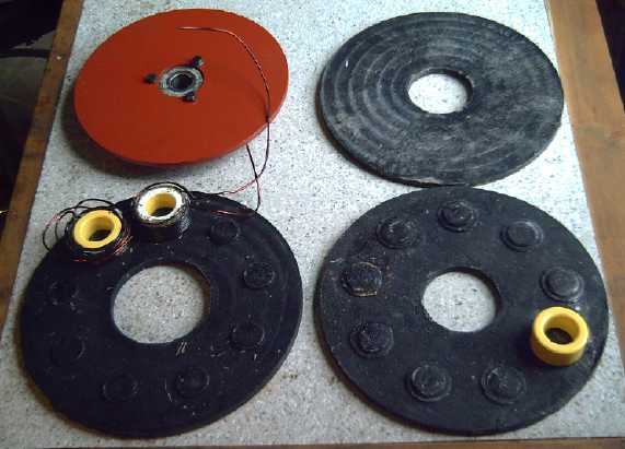
Pieces for the new motor.
Torque Converter - new concept: Torque Amplifier
After disappointing results with the magnetic
impulse converter idea and then with a centrifugal clutch system on the
motorbike, I came up with an idea based on an entirely new
principle. AFAIK no one has ever managed to create a gear with a
variable
reduction ratio.
Surprise! - There is a way to do it, with a common type of gear.
 A
planetary gear has three
elements. It can be used as a 'torque amplifier' somewhat akin to
a three element tube or transistor electronic amplifier. The trick is
to drive the sun gear and
(using the ring gear and the planet gears assembly interchangeably as
convenient) let one gear slip 'backwards' (compared to the other) at a
controlled
rate as the other gear turns 'forwards'. This slows the rotation of
the gear that turns the driveshaft, since their ratios all relate to
each other, thus raising the reduction ratio to any
higher
figure.
This allows
both high torque for squealing the tires or climbing gracefully up
curbs and over parking lot
bumpers (where the car will then hang up on its center), down to the
gear's design
ratio
for
highway speeds without excessive motor RPM.
A
planetary gear has three
elements. It can be used as a 'torque amplifier' somewhat akin to
a three element tube or transistor electronic amplifier. The trick is
to drive the sun gear and
(using the ring gear and the planet gears assembly interchangeably as
convenient) let one gear slip 'backwards' (compared to the other) at a
controlled
rate as the other gear turns 'forwards'. This slows the rotation of
the gear that turns the driveshaft, since their ratios all relate to
each other, thus raising the reduction ratio to any
higher
figure.
This allows
both high torque for squealing the tires or climbing gracefully up
curbs and over parking lot
bumpers (where the car will then hang up on its center), down to the
gear's design
ratio
for
highway speeds without excessive motor RPM.
If the slip gear slips
freely,
the output won't move at all. If there's no slip, the designed ratio
applies. If it slips at 3/4 speed, the output 'gear ratio' is
quadruple, eg 12
to 1 instead of 3 to 1. Like the base of the transistor, it
takes little energy to control the slip rate to control the reduction
ratio.
Once this new idea was established, potential ways to
control the slippage of the ring gear soon came
to light. One "magnetic brake" idea would even
reduce the drive ratio towards 1 to 1 at highway speeds - "overdrive".
The various ideas for controlling the slip proceeded in
theory in my head combined with
looking over various items of potentially fitting hardware. Another
project took precedence, but I started construction of the simplest
type on the 29th for the Sprint car, using
a 10" V-belt pulley for a manual gear-slip clutch. A rope will tighten
around it to reduce or stop the slip gear (planet assy) slippage. On
the 30th I carefully ground the end of a 1" round shaft into a pentagon
shape so it would fit into the 30 spline fitting on the ring gear, to
drive the chain drive to the differential.
The sun gear (goes on the motor shaft) will be the most
difficult to fit, as it doesn't quite fit a 1" shaft, and also it has
no spline or alignment key to keep it from slipping on the shaft. Also
I need to finish the new motor to attach it to.
NiMn alkaline Battery Production
 The engineer at Changhong
batteries was very interested in my idea for simply making 2 volt
nickel-manganese cells from the
same production line that they use to make flooded 1.2 volt
nickel-iron,
nickel-cadmium and nickel-metal hydride cells.
The engineer at Changhong
batteries was very interested in my idea for simply making 2 volt
nickel-manganese cells from the
same production line that they use to make flooded 1.2 volt
nickel-iron,
nickel-cadmium and nickel-metal hydride cells.
But he wanted
performance and cycling information that I can't supply without
producing a
practical Mn electrode myself, putting it in a Changhong NiFe battery
in place of the iron, and running fairly extensive tests on it and
charting
readings over some months.
Then some academic skeptics convinced him it probably
wouldn't work -- and if it did it would have short cycle life. This
double
denouncement is typical unreasoned resistance to anything new by
"experts" who think they already know everything, so
there can be nothing new under the Sun. Evidently this is no different
in China than anywhere else. It's easy to just ignore a new
idea being put forward by - naturally - just one person, and if he
persists in trying to explain it, just put him down as being a quack
without making the mental effort to consider the issue fairly on its
merits. A lot of creative people
with fine new ideas and discoveries are accorded this treatment. If I
pushed hard enough, I might just convince them to make a batch, but
with no belief in it, they'd probably do a shoddy job somehow, eg, of
the zinc plating, and without trying to figure out what went wrong, say
"See, it doesn't work; you wasted our time." and then they'd be almost
impossible to approach again.
It's a vexatious
delay and addition to my workload. All they would have to do is
interrupt production of negative electrodes and make a small batch of
them to see for themselves -- then either they've lost some bit of
production and satisfied their curiosity, or they change the world.
Jungner or Edison, the creators of their battery production system
(they bought it from Varta in Germany), would have dug right in with
enthusiasm.
However, I also still want to make DIYable battery
constructions, and now I expect to be able to make good Mn electrodes
(read on) and get performance and cycling data, so I just said if it
was too hard for them to make any to try for themselves, I'd get back
to them in a few
months when I've done the tests and got the results myself.
I noticed an unusual
type of electrode briefly mentioned in Alkaline Storage Batteries:
copper and iron powders, pressed around a fine wire
screen (a metric ton per square centimeter of pressure), and then
sintered to fuse copper particles together. This made a porous,
sintered iron electrode that
wouldn't fall apart in a flooded cell, without needing a perforated
metal outside casing. The sintered copper throughout gave it higher
current capacity than the pocket cells.
I'm going to try to do
the same thing with zinc and manganese. (or zinc and MnO2?) With the 1%
stibnite that I found makes Mn negatrodes work, of course. Zinc will
need less pressure than copper and can be
sintered in a regular oven. If it works, it would be the easiest for
DIY, including for me, and it should have excellent conductivity. I
ordered fine zinc powder.
If that works, the last main hurdle for usable batteries
will be a positrode with good conductivity. A rolled out sheet of
grafpoxy had puzzlingly high resistance, making me doubt the value of
an idea to make "grafABS" to make
injection molded conductive ABS plastic pockets - square or rectangular
cylinders or
hollow plates, and minutely perforate them with the IR burning laser
diode.
Another idea occurred to me. Use the expanded graphite
sheets I gave up on earlier, but in perf plastic pockets: Make tall,
thin pockets, and cut 'bars' of the graphite sheets that would go along
the back of the pocket from the bottom, out the top, and up through the
lid of the cell. In this arrangement, as they swelled up inside the
pocket after the cell was filled, they would (presumably) compress
against the electrode substance more instead of loosening. The top of
the each bar would get a hole through the lid, and a bolt through
itself above, to
make connections.
Motor Controllers (Yay!)
Mid month the IR2133-V2 circuit boards finally arrived,
beautifully done with solder masks and silkscreened component outlines
and
I.D.'s. I found a mistake (mine) and decided to add another pin
improved for
microcontroller overcontrol, so there'll be a "V3" board. But not
before I've made a few V2
motor controllers - one for the Sprint, one for the Tercel, one for the
outboard, one for the
shop, and three for the big 15 KW Weel motor. (Yikes, that's seven,
plus any I sell!
These 10 circuit boards are going fast!)
Ordering components was another grueling 4 hour session on line.
On the 16th and 17th I re-fitted a previous controller
chassis with
the new board and parts, and on the 18th I ran a motor - *the* motor at
the moment - with it. It worked great.
On the 20th I proposed to a company by e-mail to convert a
small ferry to electric using one of my motors and controllers inboard,
and several solar panels on the roof. (They said no.) The same day a
fisherman from
Port Alberni phoned me asking about putting an electric motor on his
30' trawler for trolling, and I gave him a very similar proposal but
with just two or three panels. The deal ended as an electric outboard
to try out
before committing to anything else.
Someone said there were BLDC motor controllers, 42 volts,
120 amps, in the hobby shop for 220$, so I was wasting my time making
my own. I went and looked. They did. But, first, it was just a small
circuit board with a metal plate and some medium fat but very short
wires. No chassis, no breaker & on-off switch or main fuses, no
cable
clamps... those would all be add-ons. Second, it
was for short duty use, with no serious heatsinks. The seller said
model
airplane flights were maybe 10 to 20 minutes and he wouldn't try
running it for an hour or two. Third, I suspect if it hit 45 volts or
150 amps it would blow. Mine can do to 60 volts, and could probably hit
200 or 300 amps for brief periods. And it's advanced "CRM" or "direct
torque control".
Compared to the hobby controller, the Turquoise BLDC
Motor Controller is easily worth 500$ and more.
My theory of Thermomagnetism - Magnetic Motion
Machines
The project I put the torque converter on hold for - crazy
as it seems at first - was a magnet machine that would keep turning
itself. It stemmed from other ideas -- partly from the magnetic field
drive for spacecraft
idea and partly from an early attempt to make a magnetic torque
converter,
where it seemed my design would create perpetual propulsion. At the
time, I thought surely I must have had something figured wrong. But
here was the same conclusion popping up again when a similar idea was
considered.
demo seen on the web...
 I've always been skeptical of 'perpetual motion', but magnetically
and in theory I couldn't see why this wouldn't work: a push by
magnetic repulsion (or attraction) in one direction, but no force in
the other
direction
owing to mechanically holding each armature magnet above the main
strength of the field until just before or after it passed a stator
magnet.
I've always been skeptical of 'perpetual motion', but magnetically
and in theory I couldn't see why this wouldn't work: a push by
magnetic repulsion (or attraction) in one direction, but no force in
the other
direction
owing to mechanically holding each armature magnet above the main
strength of the field until just before or after it passed a stator
magnet.
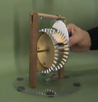
Among all the purported magnet machines I found on the
web, most of which were probably phony, one both looked plausible and
was
simple enough to grasp the
workings, and it worked essentially by this very principle. A magnetic
piece, usually a ball, will accelerate down a "V" shaped magnetic ramp,
either by attraction or repulsion, and shoot off the end. There are
lots of videos of magnetic ramps working on youtube. This machine puts
a
"V" ramp onto a circular rotor, and a device pushes the stator magnet
out of
the way momentarily when passing the end/start point of the ramp, just
when it would otherwise create an equal magnetic reverse force that
would arrest the
spinning at that point. Thus the cycle would repeat. As the animation
[taken from a longer movie from which the still image is derived]
shows, a smaller magnet at the bottom also jumps in half a cycle later
- doubtless an extra kick is gained at that
point. I'm guessing it doesn't quite keep turning without that. So,
energetic
as it looks in the animation, this design, assuming it does really work
and isn't a fake, probably wouldn't put out more than a watt or two of
useful energy without stalling, and the light forces only work because
of very
low friction. (Eg, note that the [low friction aluminum?] arm hits on
what
looks like a ball bearing race at the top rather than on the support
itself, for lowest friction.)
A friend who is involved with testing for the New
Energy Congress said he's always fighting off 'perpetual motion'
devices. He
devised a "feather test": If the device stops moving with a feather
rubbing on it, it's rejected as being unable to create a useful amount
of energy. This is a good and pragmatic test, because it sets aside
arguments about whether something is theoretically possible and
separates demos, whether they work or not, from machines that can
actually do useful work. He said that so far, none presented have
passed the feather test.
Back to the topic... here was something that magnetically
looked
theoretically possible - and that had been done and was being used
according
to some - but thermodynamically seemed theoretically impossible. I had
heard no coherent, understandable explanation of where the apparent
energy
was supposed to be coming from. "Zero point energy" was no explanation
for me. If these things worked as seemed magnetically possible, the
energy must
come from somewhere - but where?
Last I heard, we see the effects:
that magnets have force that can move certain materials, and we know
the relationships between magnetism and electricity,
but no one knows just what magnetism is or how it works.
A key is that energy is neither created nor destroyed. So
regardless of single versus 'perpetual' (cyclic) motion, where does
magnetic force and energy come from in the first place?
A stationary object appears energyless -- but it
does have internal energy: its heat.
My
theory of thermomagnetism is that
magnetism is a transfer of force and energy between
the small
scale vibrational motions of the atoms in the magnet - its
heat - and the larger scale directional forces with
the potential for creating large scale motion that we observe as
magnetism. (How it does this I'll leave to the nuclear
physicists.)
If an object is pulled away from a magnet against its
magnetic pull,
or pushed towards it against its repulsion, the energy required to
force that motion is transferred to increased vibrations within the
atoms - in other words, the magnet is heated up.
If an object is
permitted to be pulled towards a magnet by its tug, or if it is
permitted to be pushed away by its repulsion, the energy
expended by the magnet in the
pulling or pushing comes from the vibrations of the atoms: the magnet
cools.
The magnetic energy versus the heat energy would be an
exact 1 to 1
correspondence, energy used pulling an object = heat energy lost within
magnet.
Normally the one time heating or cooling effect is
imperceptible.
But if the theory
is right, I had the thought that one
might be able to measure a temperature drop within the
magnets as a self spinning machine continues to turn, especially if it
was doing
real work. I
chanced to meet a coast guard vessel marine engineer who seemed very
interested in
such
things on the 23rd. He said he
had actually
seen a
small magnet machine that someone pulled out of his pocket. Set on a
table, it
started turning and just kept going. When I told him the theory, he
said that people have observed that working magnet machines get cold,
but that
no
one
understands why. That certainly tied in nicely with the theory. Perhaps
magnets in magnet machines need heat sinks... to keep them warm!
He also
said certain machines he'd heard of "warble" up and down as they turn
horizontally, which
sounded exactly like my "take 3" design. I devised a fairly simple test
for the theory but haven't tried it. (in the detailed project
writeup)
There is precedent
for this 'reversal
of entropy': a refrigerator or heat pump extracts more heat energy from
a cold object, transferring it to a warm object, than the energy used
to effect the transfer. On the face of it, this "overunity" efficiency
too might well sound impossible, and too good to be true. Except that
we're familiar with it and we all know it works. A physicist said it's
been calculated that as much as 1200% heat transfer could theoretically
be gained with present types of systems. (Hmm... could you
run a turbine with the transferred heat and have it power the heat
pump? Yikes! - another potential means of creating 'perpetual motion'?)
A practical magnet machine
with substantial torque and power to do work of course would have broad
implications. Free
energy to make electricity would be always available, day or night,
windy or calm, winter or summer.
There seemed to be nothing for it but to make a machine and find out
whether
I had
something figured out wrong, or if it could actually be made to keep
turning. At least I had a theory to explain how it should work -- and
if I was wrong, it
would seem I at least have quite a bit of company. I figured I
could afford a few days to try a few things out and I did. The design
progressed with half built models which weren't completed to the point
of operating, but which each helped conceptualize something better and
progressively led from things that would have been demos to a design
that attracted the armature pole as it approached a stator magnet, then
flipped it as it passed, and repelled it afterwards. If indeed it
worked, it would be likely to have enough torque to
actually produce usable power. It would take a very large,
stiff feather to stop. But the tricky pivoting parts wouldn't be made
in a day and I thought of several variations on the theme by the end of
the month. Better to work on other things for a bit, play around with
the magnets by hand, and let the forming thoughts be attracted or
repelled in my mind.
Electric Cars(!)
Jim Harrington (doing the diamagnetics experiments on the
Ecosat satellite that somehow got me started on the above), bought a
Mitsubishi iMiEV on about the 12th. This time, they were
right there on the lot - four of them - and he had no
arguments or hassles. It was around 30000$ with a trade-in and a BC
5000$ incentive to buy a new EV or
hybrid car. (I think the BC incentive program is actually working!) I
expect 10,000 $ or more of the price could be attributed to the lithium
ion
batteries.
On the 22nd we drove out to Goldstream Park marina in it
to his electric outboard sailboat, and took a 3 hour cruise to check
the performance of his system with lithium ion batteries in the
sailboat. The car was lovely and had lots of power. The boat motor
ran well as long as we kept the current under 40 amps (@36v=1.44KW=2HP
of electricity), which was the limit of the lithium ion battery
charge/discharge controller. It was a lovely, sunny, rare day's outing
for me. I've never seen seals just floating out in the water sleeping
with their flippers sticking up before. I thought they were two
floating
logs with branches. We were moving right along, but so
quietly that we got pretty close before they lifted their heads and saw
us.
A former co-worker, a retired plumber, visited on the
16th. He had
spent nearly 20,000$ converting an S10 pickup truck into a very nice
electric
vehicle, over a 3 month period with parts from Canadian Electric
Vehicles and assisted by his
son, and
he's enjoying it very much. 4500$ of the cost was for 24 lead-acid golf
cart batteries. He had stronger back springs installed to handle their
weight. He retained the manual transmission. I got a ride. It was
interesting that
there was no need to put in the clutch to start, or while the truck was
at rest, since both the vehicle
and the motor were stopped. The clutch was only for shifting between
2nd, 3rd and 4th. (First gear was only for spinning rubber.) His motor
was over 40 KW,
delivering up to 32 HP. At one point we were drawing over 100 amps
during acceleration per
his handy little dial on the dash: at 144 volts, 14400 watts. He said
it can go up to 300 amps.
At the VEVA.ca Victoria meeting on the 18th, someone
brought
a Nissan Leaf and three of us got a ride. There are evidently
about a dozen of them around town now. The
Leaf is a beautiful car, and very quiet. Stopped at a traffic light
with the windows up, it was eerily silent inside. The acceleration from
0 to 50 Km/hr was astonishing - it would leave typical gas cars in the
dust. The price tag was about 40,000 $.
Also at the VEVA meeting
was a great looking electric tricycle, brought by the maker. It
had bicycle type wheels and a bicycle hub motor on the right rear
wheel. One "feature" I didn't like was 3 "U" brackets going just around
the tire on each back wheel. If he doesn't put on proper fenders to
cover those, somebody's gonna lose or severely maul a finger in one. He
said he doesn't
make a lot of money on them, but he's doing what he likes to do.
My friend and his son also put in an appearance with the
electric pickup truck. (And the owner of the Leaf turned out to be a
onetime plumber who had worked for the pickup owner's father long ago.)
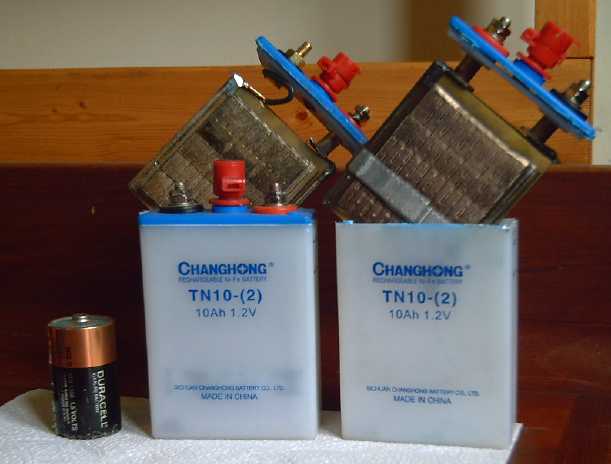
As usual I showed new people my 30 NiMH D cell car battery
(the present six 6V pipes set is now about a year old and still working
like new, which is (iirc) already better than my last lead-acid). And I
showed some 12V LED car lights starting at 1$, a fraction of Victoria
store prices, but nobody bought anything. (Perhaps I shouldn't have
mentioned they were "from dealextreme.com".) Oh well, I'll want many of
the lights for the Sprint and all the batteries I presently have for
whatever car I first electrify.
So if electric cars are taking off anyway, what's my stuff for?
It's really great to see these things starting to happen,
but the costs and the high powered systems, remind me why I'm doing
this work. The torque
converter
alone (at last looking like a pretty sure bet), should eliminate much
of the 30-40% loss of the typical automotive transmission as well as
provide a high ratio to get a vehicle moving, so substantially less
power will be needed for propulsion - 2/3 as much at most. This would
drop the price of cars a by a few thousand dollars in batteries and
motive power requirements as well as improve both low and high speed
performance. For the pickup, it would immediately shave 1500
$ off the lead-acid batteries, and by dropping 1/3 of their weight and
eliminating the transmission, it
might have meant leaving the regular springs in, and a smaller motor
and
all the paraphernalia that goes with it, further reducing the overall
cost.
The Electric Hubcap wheel drive system as a whole would
allow sizing still smaller batteries and the minimal 5KW motor size -
for a typical day's city driving rather
than a maximum range (since the gas engine can take over for longer
trips and on the highway), further reducing the battery cost and added
weight.
Then of course a cheap, high energy density battery would
be just the thing for any EV system and for off-grid storage as well.
Presently NiMH dry cell battery sticks are little if at all cheaper
than lithium types.
Nickel-manganese from ChangHong looks very promising as a first
offering using one of my chemistries if I can get them convincing
performance and cycling data from homemade electrodes. Those might
cost about 300 $/KWH - not a lot more than
lead-acid for a much lighter battery that should last much longer, and
about 60% of the price of NiMH dry cells or lithium ion types. Mildly
alkaline permanganate-manganese will be best of all and cheapest if I
get good electrode constructions, and if the permanganate positrodes
prove to have have a long cycle life. (Nickel manganate-manganese would
also be pretty economical if the permanganate has problems.)
And then, if the magnet machine proves to work and to be
practical, it changes everything again. Not to think of all the other
potential uses, a car needing no external power may need only a few
batteries for when a surge of power is required - or maybe even none at
all. Could it even replace the electric drive motor? (Hah! NO WAY will
it replace the torque converter!)
The White Background
The seemingly perplexing lack of action on renewable
energy and electric transport got me going on the green energy
projects. That started waking me
up to the evil forces frustrating the progress that everybody wants in
principle, tho so many seem indifferent to. Only a few are deliberately
hostile. The
black spots often get me indignant, but
it must be remembered that they're just black spots on a white
background, not the other way around. And lights are being shone on
them, exposing them to
increasing public scrutiny and criticism for eventual correction.
Forgiveness, mercy and enlightenment to those who today foolishly
perpetuate the problems without a thought for others, the future, or
their own real best interests. Let's all start pulling together.
("Do you not realize that the hope of a better nation — or a better
world — is bound up in the progress and enlightenment of the
individual?" - Jesus)
From a
broad perspective,
evils of a century
ago, or farther back, could hardly take place again in a similar way
because we've evolved beyond them. In the 1960's fish
returned to the Thames river after a century's absence due to
pollution, and
I hear lake Erie has largely returned to health. (thanks largely to the
invasive Black Sea mussels filtering the water.) Recycling is replacing
open ended dumping and use of materials leaving deleterious wastes is
decreasing.
Spiritual, cultural, scientific and technical progress can
be thwarted for brief periods, even a century, but they continue
progressing even unseen and arise again to be adopted in new forms. Our
vast and accumulating knowledge base can hardly again be burned and
lost with worldwide dissemination and storage of information. Let us
transcend present problems with all the newly appearing sustainable
technologies and with new, superior organizational structures.
Various
means of harvesting energy are proliferating and, along with the
upcoming world population decline, there will surely be abundance for
all.
Today's evils will be gone in another fifty years or a century and the
races will have moved far
towards social and physical sustainability and human brotherhood. Often
in fits and
starts, and often
painfully, the world progresses.
The universes were created to evolve towards perfection; that isn't
their starting condition.
Electric Hubcap Motor System
The motor on the motorbike, a 2011 prototype, didn't seem
to run very well for the magnetic impulse torque converter test at the
start of the month. A couple of days later, I tried swapping phase
wires around. Yep. That was the problem. It ran great once they were
right. It's funny it can run well enough to fool you in two of the six
possible combinations of wires.
That means the magnetic converter didn't really get a very
proper test. At first I thought I might try it again sometime with a
modified design, but the planetary gear torque amplifier would seem to
be the way to go. There may be some magnetic way to accomplish the same
thing, but I haven't figured anything like it out.
The prototype motor got munched by sudden transverse force
in the next test with a centrifugal clutch. The molds for future
motors had already been improved. I made a couple of additional
improvements - a better mold already planned, and a change to the rotor
compartment so the 'corner' where magnets were getting out if they came
loose was now the sealed side, with the joint in the outer corner,
behind the magnet rotor.
I have a couple of prototype motor shells, but I guess I
won't use them. I might be able to cut down some of their plates to the
new slightly smaller size and use them as rotor ends since they'd be
the same (except for having oddly placed [but usable] vent holes). That
would reduce the waste of pricey epoxy.
Motor Controller: Battery Wire Clamp Assembly
I had made a copper bus with a clamp to connect from the
fuses to the main supply bus inside the motor controller. But before
the power would get to that point, it was now bothering me that for the
motorbike unit with (so far) no internal breaker or solenoid that the
power wire bolted to, unless the battery wire was clamped to the motor
controller chassis, it was only held in place by the fuses connecting
it. If the fuses pulled out (and there was nothing but friction to
prevent it), the main battery wire, unfused, could touch anything -
BLAM! I didn't want to use it any longer in that condition, much less
supply such units to anyone else.
Even where there was a breaker, switch or
solenoid/contactor relay terminal to clamp the battery leed to, the
connection at the fuses, albeit short and internal, was floating
around loose. So I set out to make something better.
After considering things like making a copper plate (that
would need a
torch to solder the fuse holders to), I simply unsoldered one of the
four fuse holders, drilled and threaded a hole in the plastic under it,
and put a machine screw through the hole in the copper bar into the
plastic. Three 40 amp fuses instead of four is plenty for the
motorbike. Good enough!
For the next one, however, I made flat #18 guage
nickel-brass plates, with
the heavy wire clamp on one end, and with two more holes (total 6) for
four
fuses and two hold-down bolts. Nickel-brass is stiffer than copper, so
the #18 wasn't too thick to solder to.
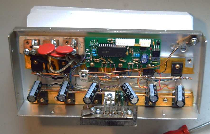
IR2133 V2 Circuit boards arrive, & 'new' motor controller
After not hearing again from the circuit board company, in
March I had had a new idea: Since they couldn't seem to read the
attachments in my e-mails, I gave them the web link to the design where
I had posted it on my web site. They had no trouble with that. I wish
I'd thought of it long ago.
On April 10th the long sought boards arrived. I had only
asked for double sided, but they did solder masks and a silkscreen
layer with the part outlines and numbers as well. Beautiful and very
useful! There's less chance I'll make a mistake putting on the parts.
Since the boards are so much cheaper from this Chinese maker, I'll have
them
done that way from now on...and stop putting text on the top copper
layer.
 A couple of
days later I decided I should make one up.
First I put some parts on the board to see what I needed to order
besides
the 74ALS86 SOIC XOR gates. Then I did a little editing of the PC board
- already I can see a version 3 will be desirable. Worst feature: a
trace I hadn't re-routed after moving a part was shorted to a pin.
Rats! I'll just cut the traces and hard-wire it for these 10
boards. Anyway, nice to notice it before trying to run it!
A couple of
days later I decided I should make one up.
First I put some parts on the board to see what I needed to order
besides
the 74ALS86 SOIC XOR gates. Then I did a little editing of the PC board
- already I can see a version 3 will be desirable. Worst feature: a
trace I hadn't re-routed after moving a part was shorted to a pin.
Rats! I'll just cut the traces and hard-wire it for these 10
boards. Anyway, nice to notice it before trying to run it!
Then I got on line for a grueling 3-1/2 hour session
ordering parts at Digikey Electronics. I was somewhat perturbed to
discover the IR2133 MOSFET gate drivers are now over $15. Maybe
somebody's using my
design and the demand is high? - there was interest on a motor
controller
list, and I did put the design on the web. Perhaps I'm not even the
first to make my own PC boards?
I spent the 16th,
and a little time on the 17th, putting the new controller together in
an old chassis. Most everything had to be moved, redone or just done,
so I didn't save much work over
building a new one from scratch except the sheet metal fabrication.
(Even there, a chassis side piece had somehow gone missing.) I
made new style wire clamps and a
fuse "platform" on plexiglass. On the 18th I tried running the one
working motor, and after a few hiccups, it worked great. (2
diodes that went bad, and
crossed phase
wires. I threw out the rest of
those diodes. Someone gave them to me long ago. Always look gift
components in the mouth.) I didn't do extensive tests. For a change I
checked the RPM. With only 24
volts instead of 36 I could get the motor over its design speed of 2000
RPM.
Yikes! What horrendous speed was the one going that flew apart at 42
volts?
Someone said he thought I was reinventing the wheel: the
hobby shop had similar motor controllers for 220$. I went and looked.
The largest controller they had was indeed rated 42 volts, 120 amps for
large model airplane motors. However, the salesman expressed doubt that
it would work for driving a car. He said the airplanes might fly for 10
or 15 minutes - he wouldn't try running it for an hour. "Hobby use
versus industrial." he shrugged. Nor would I trust such a small unit on
the road. In addition, while I'm calling it "40 volts at 130 amps",
I've used 48+ battery volts, and they'd probably take well over 250
amps momentarily. There are enough unpleasant external surprises on the
road without adding internal ones. I wouldn't be surprised if the hobby
shop board would blow in a moment at 45 volts or 150 amps, and it
didn't have a heat sink capable of dissipating the heat of sustained
high power operation.
Aside from that, the Turquoise Motor Controller comes in a
heavy duty aluminum chassis wiring box and includes a breaker-switch,
fuses, and optionally a solenoid to turn on the power remotely. Theirs
is just a circuit board and all the other parts have to be added
externally - it would all add up to maybe 400$ plus labor. This makes
500$ for my heftier premade unit seem like quite a reasonable price.
New Electric Hubcap Motor - With Layout Improvement
By the 23rd, with two working motor controllers now on
hand, I started getting concerned that if I managed to sell a system, I
would have no working motor. Soon someone did in fact want to try out
an Electric Hubcap Outboard, which has pre-empted this motor. I was up
in the air whether to work on the
torque converter or the magnet machine. Instead I molded a new stator
end piece for a new motor and thought about the next steps on the
others. (150g PP cloth; 600g epoxy. This is the plate that takes the
stress of the magnets pulling towards the stator, so I'm making them
pretty thick.)
Then I made a new mold for the center ring piece,
with
bumps for the coil centers but no shoulder around them. The coils will
definitely be affixed in place on both plates, and the slight overhangs
of
wire will face out, while the cores will butt right up against the
center ring as close as possible to the magnet rotor.
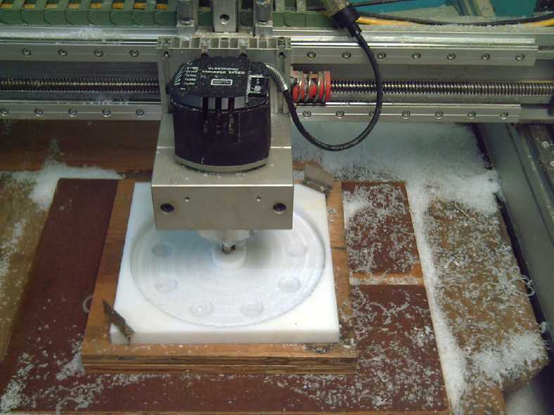
New inner stator plate outer face mold
1" thick x 12" x 12" 'butcher block' UHMW polyethylene, made on 26th
I think I'll use for both stator plates - it'll hold the
heavy #11 wires on the coils better.
Some
reinforcement ribs might also be feasible... hmm, another new good
idea! Will I ever have a final design? But I couldn't see anywhere
substantial ribs would fit on this inside piece. On the outside of the
outside piece might be a good place. If it had some stiff ribs, I might
trim 100 grams off it in thickness and still have the desired stiffness.
On the 27th I made the piece in the new mold, using 100g
polypropylene "landscaping" cloth and 400g of epoxy - thinner than the
outer piece because it takes less stress and because its thickness sets
the minimum distance the magnet rotor can be from the tops of the
coils. Since the present motor can easily be overrevved, it would be
nice to reduce the gap, decreasing speed and increasing available
torque. This piece should allow a gap as thin as is magnetically
practical anyway,
about 1/2".
I found a magnet rotor already zinced and polyurethaned.
Among some plywood reinforcing pieces for the molds I
found also a rotor end piece I must have made a while back. That's two
more little motor making jobs done. So the last molding job is the
outside circumference of the rotor
compartment, and in fact it will be the first one done from scratch
with the mold setup made for that.
Pieces for next motor
First I have to decide where to locate the holes in the
stator plates. Originally, the coil holes went at left and right inner
edges
of the toroid cores to keep them in place (at least left and right - in
and out there was some undesirable free play). Now with the composite
buttons
keeping the coils in exact position, the bolts could be closer to the
centers of the cores, and the extra thickness of the buttons gives more
material to screw them into. (Metal nuts by the spinning rotor magnets
are undesirable.) A few more bolts at the inside and outside edges of
the plates wouldn't hurt either, if space can be found to place them.
Then I have to calculate all those hole positions and set
it all up as a CNC drill program. Sigh - I could use some CAD/CAM
software.
Remake of the Honda Outboard motor
A fisherman was interested in putting an Electric Hubcap
motor on his 30' trawler. But if it proved to have insufficient thrust
for trolling or the project otherwise proved unworkable, it
would be a considerable wasted investment in time and effort to install
and remove.
Instead we decided I should put the electric outboard back
together, and he should make an outboard mounting on the back of the
boat.
If it didn't work out, I'd still have the outboard and he'd have a
mount for any small outboard.
A glitch to the program was that the original motor had a
9" rotor and was a little smaller than the later units, and it was an
open frame with no case. It just fit under the Honda hood. The new
motors don't quite make it.
Somewhere in the process of trying to fit the motor, I
found that most of the surprisingly strong gear noise in the
previous version was because the motor was pressing down on the drive
shaft. If it didn't press down, it was quiet.
5 Amp NiMH Battery Chargers!
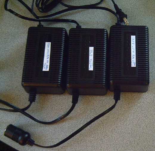 A
while back I bought ten 12 volt, 5 amp power
adapters with 'cigarette lighter' output cords at XS Cargo for 3.99
$ each. One thought was to use them for 12V LED lighting. Another was
to convert some to 13.8 volts for 12V NiMH constant voltage battery
chargers.
A
while back I bought ten 12 volt, 5 amp power
adapters with 'cigarette lighter' output cords at XS Cargo for 3.99
$ each. One thought was to use them for 12V LED lighting. Another was
to convert some to 13.8 volts for 12V NiMH constant voltage battery
chargers.
This month I opened one, found the specs on a tiny surface
mount "shunt regulator" IC inside (that I didn't even see at first - a
"programmable zener diode" I'd call it) on the bottom of the PCB, and,
seeing how it worked (praise the web), I changed a resistor for one
with a slightly lower value. That changed the voltage to 14.1. Bingo!
I bought a package of resistors to give the exact voltage and made
three on the 28th. I put a .27 Ω resistor
in the output to limit current for quite discharged batteries so they
don't shut it
down or blow it.
I think I'll cut off the cigarette lighter sockets and put
on small (30 A) APP plugs, where plug and socket are identical and the
pins on both sides, battery and charger, are recessed. (The APP parts
cost me slightly more than the power adapters themselves did.)
Three triple 12 V chargers for three 36 volt, 5 amp
Electric
Hubcap system/NiMH battery charging units will use up 9 of the 10. I'll
want them all - nothing left to sell. One for
house LED lighting will finish them up. All for 45$! At the
time I didn't know if I really could change the voltage. If I'd checked
into converting them right away, I'd have known I wanted them and
bought about 30 while the opportunity was there.
Mechanical
Magnetic
Mechanical
Magnetic Impulse
Planetary Gear
Torque
Converter Project
The Motorbike Centrifugal Clutch Test
The installation of the
centrifugal clutch with the 10 tooth sprocket gear went amazingly
smoothly in just one afternoon on April 4th. I ground a bit of a slot
in the axle to accommodate the built-in shaft keys on the clutch with
the angle grinder without taking the motor off the bike. That went
well. I left the output drum slightly off-center. A steel tube I
happened to have handy proved to be the exact size and wall thickness
needed (!) to make a shim for the input, and in a can I even found the
right size shaft collar to hold the assembly on. And I finally figured
out how to adjust the chain - by moving the back wheel ahead or back a
bit. I became uneasy about how well and smoothly the making was going.
That surely meant something would go wrong in the test. Was I becoming
superstitious?
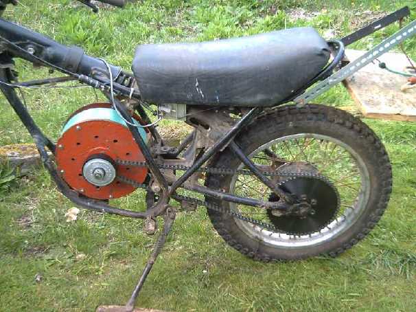
Anyway it looked good
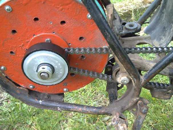
Centrifugal clutch assembly on motor.
The black output drum was mounted slightly off center.
Then I spent a day (6th) improving the motor controller
and making a nice battery box and more 6v battery sticks to have two
banks of 36 volts. (See NiMH project.)
The test on the 7th was a disaster. The motor was turning
faster than
I thought it should need to before the clutch cut in. That's probably
because it was made for high RPM gas engines. Suddenly everything
jammed to a stop. The motor was broken and 9 of 12 magnets had come off
the rotor. This was the oldest prototype motor having the
polypropylene-epoxy housing pieces, and it had an old car disk brake
rotor
instead of a flat rotor, dating back to the lossy metal stator plate
designs.
I pieced together the most likely scenario the next day.
The clutch probably suddenly grabbed and the chain yanked tight,
pulling the axle sideways. I've been a bit nervous about using this
earlier prototype motor with the culvert pipe outside cover - if it's
yanked sideways hard enough, the cover and axle could be shifted
off-center,
enough that the magnets would hit the stator. Of course, a chain drive
does exert sideways force (duh!) and letting out a clutch engages that
drive suddenly. Examining the scrapes in
the stator ring and the paint from that ring on the top of some magnet
surfaces indicates that this is probably what happened. The
newer molded rotor ring casings solve this problem, so it shouldn't
happen again. But I'll have to make another motor (or two) because now
I only have one.
So far, principles of operation for a torque converter
had consisted of trying to create momentary high torque pulses with
little or no torque between, wherein the motor recovers its speed. Some
of these means have been mechanical, others magnetic. A major problem
has been finding a system where the motor isn't held stalled if it
moves too slowly into a "torque pulse zone" or comes to rest in one.
Thoughts about centrifugal clutches as a means of
obtaining momentary high torque that would disengage if the motor
couldn't keep its speed up, continued and branched
out, and I came up with more than one new plan for coupling motors to
wheels. Then a fantastic idea emerged: a torque converter based on a
different operating principle entirely.
Planetary Gear as Torque Amplifier!
First, an example of an amplifier that everyone is
familiar
with: the triode vacuum tube. This has three elements: cathode (or
filament),
grid, and anode. A big flow of power, of electrons flying through the
vacuum between the
glowing cathode and the anode, is controlled by varying a low voltage
using almost no power on the third element, the control grid between
them.
(This electron beam is of course the origin of
the term
"electronics".) The electrons would happily flow from the cathode to
the positively charged anode, but if the grid has sufficiently negative
voltage, it
repels the cathode's electrons back, and there's no flow. If it's not
negative enough, or is positive,
the electrons are attracted
to the much higher positive voltage of the anode beyond, and flow to
it.
In between "off" and "on", small changes to the suppressing grid
voltage, using trivial power, make large
changes to the main current flow - amplification.
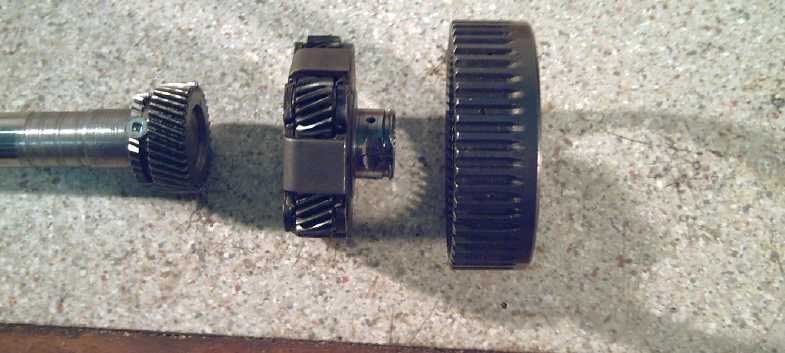
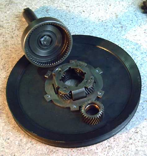
Planetary gear: Left: Sun Gear; Center: Planet Gears Assembly (may have
3, 4, or 5
gears); Right: Ring Gear.
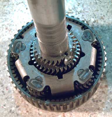 Planetary gears also have three
elements: Sun gear, Ring
gear, and Planet gears assembly. Usually one of these is held in fixed
position, and a fixed ratio of torque conversion is attained between
the other two. With my Chrysler transmission planetary, if the
sun gear is driven and the ring gear is stationary, the planets
assembly turns 1/2.8 times as fast as the sun gear. If instead the
planets assembly is held fixed, then the ring gear turns 1/1.8 times as
fast as the sun -- and in the opposite direction.
Planetary gears also have three
elements: Sun gear, Ring
gear, and Planet gears assembly. Usually one of these is held in fixed
position, and a fixed ratio of torque conversion is attained between
the other two. With my Chrysler transmission planetary, if the
sun gear is driven and the ring gear is stationary, the planets
assembly turns 1/2.8 times as fast as the sun gear. If instead the
planets assembly is held fixed, then the ring gear turns 1/1.8 times as
fast as the sun -- and in the opposite direction.
However, there is another possibility, in between these
two: if the ring
gear is permitted a limited constant backwards slip with some sort of
variable clutch or brake, the output gear (planet assy) will turn...
but more slowly
than the indicated
ratio.
The energy to control the slippage should be
small compared to that being controlled.
I haven't figured out the losses.
If the ring gear is allowed to turn backwards freely,
there's no
energy loss. Also none transmitted to the planets assembly - it (and
the car) remains stopped. The
electron beam is
"off". If the gear is held stopped, there's also no energy loss. The
beam is full "on", and the planets assembly turns at the
2.8
to 1 ratio. Half way between is perhaps the largest frictional loss
owing to slippage. But the slipping gear is being permitted to
slip backwards. I don't think the energy loss will be large. Then,
depending on the design ratio and when the ring stops
slipping, those losses might well only apply to start the vehicle
moving and during more rapid acceleration below about 20, 30 or 40
Km/hr.
The slipping of the third element is the control voltage
on the
grid of the tube. Controlling the negative slip controls the gear ratio
of the
main power transmission anywhere between approximately a zillion to one
and the fixed ratio. Either the ring gear or the planet gear assembly
can be the slip gear, and the other the output gear, as is
convenient. For one, the motor will run in reverse direction to the
other. So
what?
Unless I have something figured entirely wrong, herein is
the essence of a fantastic torque converter! This will move
cars. (It may have taken me 3 frustrating years to figure it out, but
AFAIK nobody else has done so. Persistence pays. I see nothing like it
on the web.)
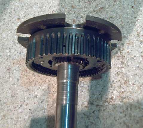
Planetary gear as it previously attached motor to Tercel wheel, planets
assembly set to move it via turning the wheel lug nuts.
It should have worked, and may yet work, by allowing a controlled slip
of the ring gear
to provide an infinitely variable ratio instead of a fixed 2.8 to 1.
There's one more
mode of operation:
if any two of the gear elements are locked together, none will turn
relative to each other, so they turn as a single unit at 1 to 1 drive
ratio. This becomes significant for certain forms of slippage controls.
Applying a controlled slip to one 'output' gear (planets
or ring gear) to use the other as the drive shaft output, can
be done in a number of ways.
Ring gear slip techniques
manual clutch
First I think I'll
try the simplest and probably surest design on the Sprint car: a manual
clutch/brake that releases the slip gear to spin freely, or tightens to
hold it stopped.
This has no slippage and the exact design gear ratio when
the gear is held stopped, as it would be above perhaps 20, 30 or 40
Km/hr except during rapid acceleration in city speed ranges.
If as I expect I can spin the
wheels on the Sprint or if it lunges into motion when I hit the
electron pedal,
it'll probably also be sufficient for the Tercel wheel even without the
Sprint's 4 to 1
reduction. (And the Sprint's reduction can be reduced or even made
unity.) If somehow I have it figured out wrong and it's another
failure,
or if the implementation needs improvement to make it work... well,
I'll find that out with the least amount of building - I think.
(I keep wishing I had finished making that pulsejet steel
plate cutter to make new steel rotors and odd shaped parts at will
instead of taking the design somewhere out of town, putting the project
on hold while it's made for me, and then driving back again to pick it
up. Then repeating the process when I find it doesn't fit quite as
expected.)
centrifugal clutch
The next step up
might be to use a centrifugal clutch. But a question is: between what
and what? A centrifugal clutch to a fixed drum is going to have slip at
all times, since as it latches it slows, the centrifugal force reduces,
and it's
released again. The gear would always be slipping backwards
proportionally to the torque required. Putting it between the sun gear
(motor, with the
centrifugal part) and the ring gear (as the slip gear, with the drum
part), with the planets assembly as the output, would have them
slipping until everything was turning at 1 to 1 speed. This would be
good with a bigger, lower RPM motor, but either leaves the units
slipping most of the time or limits motor speed more than desired,
unless a further 2 to 1 or so reduction follows the converter. A
reduction is already done under the hood on the Sprint, but would be
tricky for a wheel mounted motor.
An alternative could be to mount one element on another
gear , so that at the desired ratio, both elements are spinning the
same speed. This would be complicated.
Thus the seemingly obvious choice of a centrifugal clutch
seems to break down under scrutiny - except maybe in the Sprint or
similar conversions. There it might be worth a try at some point.
magnetic brake
After figuring out these mechanical means of controlling
the slip of the ring gear - manually or centrifugal - I thought that
the same thing might be accomplished magnetically, with a magnetic
brake. Here the loads should be lower than for using magnets directly,
making it feasible. Interestingly, this would harken back to my first
attempted magnetic torque converter and could even use the same
aluminum braking plate. Undesirably unless it proves to have trivial
loss for most driving, there would always be a certain amount of slip.
For the 'simple clutch', one element - the braking plate
or the magnet rotor - could be fixed with the other on the slipping
gear. But if they were mounted
on two opposite turning elements, at high speed and low torque the
entire assembly
could be moving forward, the ring gear element slipping back less than
the output speed. This would provide a reduction ratio headed for 1 to
1, smaller
than the fixed ratio of the planetary gear. This again might load the
motor more than desired.
As the results are less certain than for the manual
clutch, I'll save these ideas for later.
controlled generator
On the 10th
having coffee with friends, someone had a brilliant idea: use the
slipping gear to turn a generator, which would put the waste
energy back into the batteries. I wasn't sure there would be enough
waste energy to worry about, but it sounded simple enough mechanically.
Electrically, the rate of generation, controlling the
amount of slip, has to balance the desired conversion ratio at
different speeds.
Somehow I still
have the Sprint's alternator, and a loose engine pulley for it (that
fits over
the planetary's ring gear).
These take a ribbed belt. Again it would be tricky to mount on a wheel,
but on the Sprint it might work fine. It's another variant to try at
some later date, after proving with the manual clutch that the
conversion system works in the first place. And after seeing if
the slippage losses are significant enough to worry about.
The planetary gear torque converter now seems like the
obvious
way to use the Hubcap
motors to drive any wheeled vehicle. Unless I've missed something it
seems it can hardly fail except via poor implementation. (I do find
implementation of mechanical designs tricky - witness some of my
failures.)
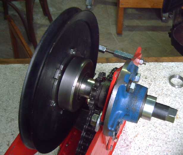
Sprint Car Test Model
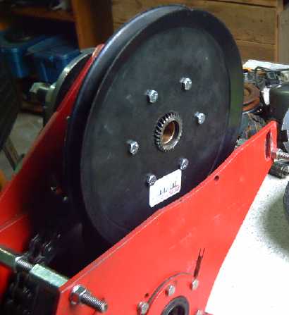
Checking the fit. Great... say, where'd the motor go?
On the 29th I found an
appropriate 10" V-belt pulley at
Princess
Auto - one with a single steel plate for the body, so it could be
bolted to something next to it. I drilled 6 holes in
this, and 6 (threaded) holes in the planet assembly of a different
model of planetary gear (the Chrysler transmission had two different
ones). This
gear seemed a good pick for this because
the planet assembly had six tabs that stuck out beyond everything else,
to drill holes in and bolt to.
It also had a closed end on the ring gear.
The pulley was thus the easy part. The output
shaft attachment is for a splined shaft. I actually have the shaft, but
it won't fit anything else except the gear. There are 30 splines, so I
thought I might be able to grind the end of a 1" shaft to a pentagon
and insert
it, if I was very careful to get it perfect. I accomplished this on the
afternoon of the
30th, spending quite some time fitting it.
At the other end, the sun gear isn't quite the right inside size for
the 1" motor shaft, and doesn't have a key or splines or anything to
lock it onto the shaft. That'll be the trickiest part.
And finally a rope, fastened at one end, has to loop
around the pulley and
then go somewhere to some clutch lever or pedal. Being (formerly) an
"automatic", the car has no clutch pedal for it... auto wrecker?
Let's see... Since the 'clutch' will be in 'some slippage'
mode at low speeds, perhaps it would be better if it could simply be
set to any given position rather than having to modulate it with the
foot. Maybe I'll put the automatic transmission lever back in and
connect it to the cable to tighten the rope. I'll change it so it can
be pulled back (tighter) readily, but will only move forward (looser)
if the button is pressed. I think this sounds like the ticket. (No
linkages to ignition key or to brake... then again, maybe it should
have...?)
Drive Belts
For the motorbike, the Sprint car, and the electric
outboard from scratch, it occurred to me that instead of chain drives, belt
drives (maybe toothed) might be better. On the outboard,
potentially a smaller pulley might be used, narrowing the leg. The
Wikipedia article on
belt drives says
that
improvements in belt engineering now allows belt drives where
previously only chains or gears would suffice... like, maybe, in
automotive drive
units, where they could make everything more efficient. Nobody seemed
to have any special 'high power' V-belts.
The high efficiency figures surprised me: "90-98%, usually
95%". They have
high tolerance for
misalignment (ideal for DIY), and are inexpensive. Clutch
action can be had by releasing belt tension. Different speeds can be
obtained by step or tapered pulleys. Toothed synchronous ('timing')
belts need the lowest tension and are generally the most efficient.
I've never thought before except in terms of gears or
chains, knowing that V-belts on small diameter pulleys have
considerable friction -- despite recently seeing the timing belt in the
Sprint engine, and knowing how much better those are than the old
timing chains. Why have belts not revolutionized automotive
transmissions? It's probably inertia - so many parts of the
transmission would have to be changed at the same time. It can't be
approached piecemeal, since present parts run in oil and belts can't be
in oil. Funny how slow we so often are to
catch on to real opportunities created by advancing technology! The
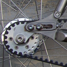
ever innovative bicycle world is first as usual. (see foto)
My original thought had been a flat, ribbed or multigroove
belt that could use an idler wheel for a clutch. Thus a clutch on the
belt, probably manual, would replace the centrifugal clutch. Toothed
belts would be better in general, but aren't amenable to being clutched.
Another thought, on reading the Wikipedia article, is to use a "flying
rope". The ends of a wire cable could be silver soldered(?) together to
make it a loop. Polypropylene rope might be good if the ends can be
fused together well. The diagonal strands in the cable would grip a
textured pulley without slipping (like the teeth of a toothed belt),
but would more easily slip to be clutch driven. I'd have to look into
pulley diameters versus cable diameters versus load capability. The PP
rope would flex better. (I adapted this idea for the slipping gear
clutch system.)
In fact, couldn't textured pulleys be used to prevent
slippage of belts having any flat bottom surface? -- or would that just
cause fast wear?
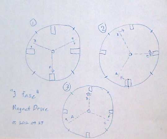
Magnetic Motion Devices
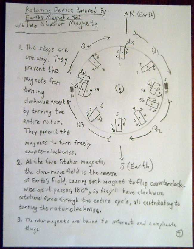 The drawing
last month showed how if a rotor had magnets facing so they would all
try to turn clockwise, the entire rotor would try to turn clockwise. In
order to keep them thus oriented, they had to be flipped around half
way between north and south on both halves of their journey.
The drawing
last month showed how if a rotor had magnets facing so they would all
try to turn clockwise, the entire rotor would try to turn clockwise. In
order to keep them thus oriented, they had to be flipped around half
way between north and south on both halves of their journey.
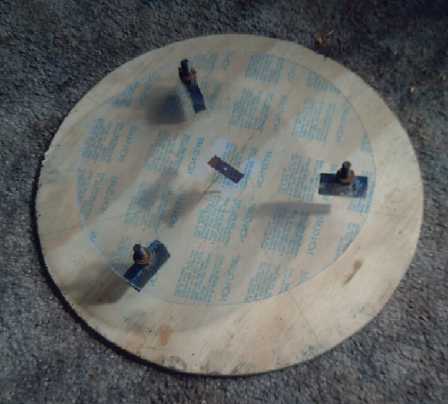
I cut a light 12.5" diameter disk of thin acrylic plastic
and scored the center point with a drill. At 120º from each other
I hung three magnets by putting a steel bolt on the top of the plastic,
which attracted the magnet and held it in place.
I drilled a hole in a piece of wood and stuck a drill bit
in it, but the device didn't work. Then I took out the drill bit and
stuck in the compass I'd marked the disk outline with, sharp point up.
This gave better results.
When one of the magnets between magnetic north and south
was turned around, the disk rotated 1/6 of a turn. Then the one on the
opposite side was midway, and reversing that one caused another 1/6th
turn. Then the next magnet was half way on the first side again, and
the process repeated. Sure enough, each magnet was being reversed half
way between north and south as it arrived at that point, and except for
having to
reverse the magnets by hand, the disk would have had continual
rotation. That demonstrated the first, and rather obvious part of the
operating theory.
The next part would be harder: have the magnets flip
around by themselves at the half way points. The forces being slight,
friction would have to be almost nothing, and the force needed to flip
the magnet would have to be very small to prevent it from stopping the
rotor.
Origin of the Theromomagnetic Theory
But what if, instead of the Earth's linear field, magnets
were placed all around the rotor with their north faces facing the
rotor? Then essentially, north would be coming from the outside and
south from the inside, and with
all the magnets on the rotor facing the same way, they would all be
trying to twist the same
direction. It started sounding more and more like perpetual motion...
but why
wouldn't it work?
Someone named Howard Johnson took out a patent for a
perpetual magnetic
motor in the 1980's, and indeed he took out several related patents. In
the patent he was ranting on something about unpaired electrons from
which energy could be extracted, and ferromagnets being a form of
superconductor. It was either BS or way over my head - I'm suspicious
that it was probably the latter.
On the other hand, I haven't heard that anyone has
successfully repeated the results... except... someone told me one
magnet motor in a patent office successfully ran for 30 years. This was
reputed to have obtained
its energy from very gradual demagnetization of the magnets. But for a
machine
to continue working for so long from such a minute energy source
stretches credulity as much as the idea of magnetic perpetual motion.
I know a
lot of people have tried and failed to produce something that works,
and especially something that one can extract useful energy from. A
dozen
youtube videos later and seeing no one intelligibly explain where the
energy is supposed to come from or demonstrate a credible working unit
could understandably leave one skeptical.
And yet... there just might be something there, somewhere.
Some
source of nuclear energy in the 'superconductive', 'unpaired electrons'
within ferromagnetic materials that could be harvested. Or was that
just like saying a diode should generate electricity because it only
pushes electrons through one way?
Then I found, or
someone send me a link to, a video of a spinning magnet machine that
looked genuine. As described in Month in Brief above, it seemed
to have the essential elements, carefully constructed.
Magnetically it
looked like it should work, and the video looked good, but nothing so
far had comprehendably
explained to me where the
energy would come from to move a rotor and keep it moving. I finally
came up with my own theory:
We see an apparently inert object, and conclude that it
has no
energy that can be harnessed. But its atoms are all vibrating. The
extent of this vibration is proportional to its temperature - is
its temperature, its internal thermal energy. Vibration stops only at
absolute
zero. My theory that magnetic actions take these
vibrations and convert them to large
scale directional force, magnetism, with the potential we observe for
the movement
of magnets and magnetic objects, is expanded above in April in Brief.
The rotation of the rotor in a magnet
machine is simply a cyclic repetitive motion of the same forces and
energies that are always invoked when magnets act.
A test to prove the theory
If this is the case, the magnets should drop in
temperature as they continually turn a rotor. It might, or might not,
be enough to measure.
Someone who seemed to have looked at and studied magnet
machines said it was indeed the case that they got cold when running -
and also that no one understood why.
Thus a test to prove the theory suggests itself: Take a
supermagnet and put a temperature sensor on it. Then take an
electromagnet with a core that's magnetically attracted. Set it up with
the magnet swinging on a
hinge, with a proximity sensor so that as it gets very
close to the electomagnet, the coil turns on for a moment and repels it
away.
The electromagnet (I'll use a motor coil) will heat
electrically in
excess of any other factor. The supermagnet will be expending energy
moving in both directions, so its temperature should
drop proportionally to the amount of work it has done.
At first I thought this suggested a new way to make a
refrigerator. Put the magnet inside, and the electromagnet outside, of
a thin, nonmagnetic fridge wall. Then I realized a fridge could
probably
be made to generate electricity instead of using it: just put a magnet
machine inside.
Let it run a generator and convert the heat in the fridge into
electricity. Electricity from a quieter fridge with no ozone depleting
gas that runs for free - it can't get much better than that!
The drop in temperature in a magnet machine would of
course be made up from
the surroundings, which are heated by the sun. Thus, the energy of the
magnetic machine is, indirectly, solar energy.
If the theory was right, the question was still, did I
have or could I come up with, a
workable magnet machine? It
seemed there was nothing for it but
to try it out.
Take 1
 For the 'all north magnets' design idea, that wouldn't be
hard
- in fact, much easier than
trying to have magnets pivot. My three magnets on the plastic disk with
the compass point would be a fair test armature. In the end I simply
placed the outer magnets all around in a circle, "Magnethenge".
For the 'all north magnets' design idea, that wouldn't be
hard
- in fact, much easier than
trying to have magnets pivot. My three magnets on the plastic disk with
the compass point would be a fair test armature. In the end I simply
placed the outer magnets all around in a circle, "Magnethenge".
It didn't work as I made it. Motive force at the stator
magnets turned to anti-motive force between them and everything
canceled out. (including with a prime number of surrounding magnets,
and regardless of the flux gaps.) I think that with no south pole in
the center, the flux lines from the north poles all facing in probably
bend around and come out again between magnets.
Take 2
What would happen if the armature magnets could pivot up
and down on arms, so that in the forward propulsion area they were in
line, but in the repelling zone they were above or below the strong
flux zone?
Then there should be net rotary motive force - if it didn't happen to
make an equal or greater slowing force to fling the magnets out of the
magnetic path. This was similar to an idea I worked on in a couple of
versions for a magnetic torque converter early on, with interacting
supermagnets. I wanted them to pull the output ahead, but not back
again, as the motor rotor passed, so I held them back with springs
(first type; not finished) or twisted them 90º (second type; was
built) to prevent attraction until they were right across from each
other. (Although it worked in essence, it didn't provide car moving
torque, and it wasn't constructed with turning itself in mind.)
As I did the first one of these converters, I realized
there was
motive force in one direction but not the other. That sounded like
"perpetual motion". Since I didn't believe in perpetual motion, I
figured
I must have figured something wrong, even tho I couldn't see what it
was. How many people have done that, I wonder, and missed the
opportunity? If you don't
believe something is possible, chances are pretty remote that you'll
take the
trouble to design and build a working model to demonstrate it.
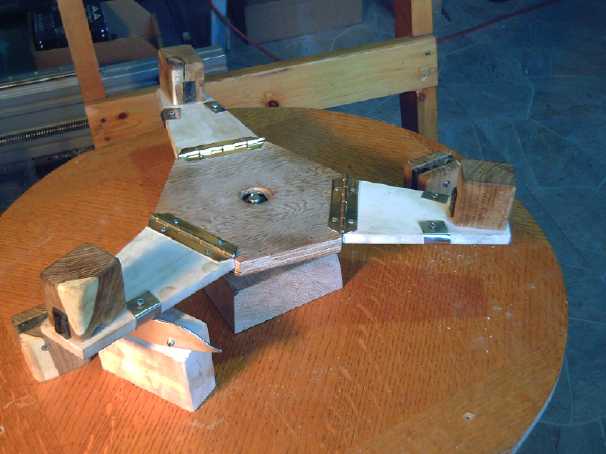 The 'take 2' unit was made in a marathon session occupying
the whole day and evening of the 13th. Woods are good materials for
this sort of prototype since they are beautiful, structural, easy to
fashion, and have little magnetic effect.
The 'take 2' unit was made in a marathon session occupying
the whole day and evening of the 13th. Woods are good materials for
this sort of prototype since they are beautiful, structural, easy to
fashion, and have little magnetic effect.
The body was a piece of eastern oak veneer
particleboard that used to be a coffee table top, cut round 2' in
diameter, except a corner was left to form a carrying handle. From the
3/4" hexagonal fir plywood center
hub, it had
three hinged arms of lightweight figured lombardy poplar each with a
magnet in a
laburnum holder, and two stator magnets (laburnum) at opposite ends
underneath the armature. Each arm with its magnet on the end could rise
up on the hinge, out of the flux path of the stationary magnet.
It took too much force to raise the heavy arms. (Shouldn't
have used the laburnum? But the magnets aren't light either.) But the
center bearing had a little play, and I noticed the whole armature
tilted a bit before an arm started to rise. This modified the plan. I
loosened the coupling
of the center axle so that the whole armature could tilt back and forth
without the arm hinges moving. That way, it was gravitationally
balanced. Lifting one magnet lowered the others, and it took little
force to lift the magnet passing over a stator magnet.
In theory, the impulse from one magnet as it passed a
stator magnet should be enough to raise the next magnet approaching the
other stator magnet. (obviously, there had to be an odd number of
armature magnets with two stator magnets, so only one arm would need to
rise at a time.) But with only three magnets on the armature, it didn't
look like there would be sufficient force to keep it turning, so I
didn't finish it. Once the magnet was raised, it had friction against
the track it rode on added to the slight repulsion of the stator magnet
as it approached. (Tho this repulsion was much reduced by the raised
height.) It
stopped without reaching its stator magnet and dropping to provide the
next impulse of force.
Take 3
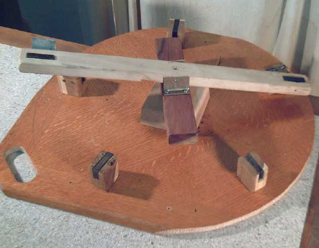 Next would be
5 magnets. It would be easier since only a
single piece armature body was needed - no hinges - and since 3 magnet
holders were already made. But it might also need 4 stationary magnets.
Next would be
5 magnets. It would be easier since only a
single piece armature body was needed - no hinges - and since 3 magnet
holders were already made. But it might also need 4 stationary magnets.
On the 14th I made two more magnet holders. Then I
realized that instead of two magnets on the stator and five on arms of
the rotor, it could as easily be the other way around. A rotor with
just two arms would be much simpler. After leaving the project for a
few days for other activities, I decided that the two ended arm piece
could hold the armature magnets, so on the 19th I mounted all 7 magnets
and holders around the base piece for the stator.
At the same time I realized that the machine would be more
likely to succeed if the rotating part had an inertial mass, a
flywheel, to help prevent it from stopping in those brief zones where
it was being pushed backwards a little bit. But it didn't need to be
round, only heavy. I used a piece of cambodian
rosewood - density .95 - and mounted it on
the center axle, below where the magnetic arm mounted and at 90º
to it.
I had thought to make the machine self-starting, but with
the 'flywheel' it would probably need a push to get it going. Then I
thought about putting another arm on it at right angles to the first.
The up-down movements of one ideally wouldn't affect those of the
other, but they would be getting thrust at different times. If it
didn't work with one arm but looked promising, two arms might make the
difference. Roughly, one of the arms would be thrusting much of the
time if not most or all the time.
On the 21st, I tried a few things out with someone
interested in helping, even with the terms being: no money, no
ownership, no patents, I publish all results. It seemed 7 magnets was
actually too many. The up-down waving of the arm would have to be too
steep. I took it apart and redid it with 5.
My helper came up with the interesting idea of putting a
magnet ahead of each stator magnet lower down. That one would push the
rotor magnet up at the point where it was supposed to start to rise,
instead of needing a ramp. This indeed seemed to much reduce the force
needed to get an arm to cross over a stator magnet. There we left it
for the day.
Take 4
The next day I started thinking of the first design again,
with the magnets flipping around. If I took the same stator with the 5
magnets, but had rotor magnets that could be flipped, what would happen?
I took a magnet and dragged it on courses around one
stator magnet by hand, trying to come up with a path of least
resistance that would take the least amount of energy to flip. I came
up with this:
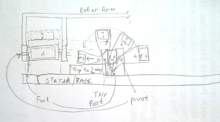 On approach to
the stator magnet, the rotor magnet is
being attracted. When the 'foot' reaches the trip block, it will cause
the magnet to flip up, over the stator magnet, and come down on the
other side. The flipped magnet would then repel away from the the
stator magnet. This way, it provides thrust both on the approach and
the departure.
On approach to
the stator magnet, the rotor magnet is
being attracted. When the 'foot' reaches the trip block, it will cause
the magnet to flip up, over the stator magnet, and come down on the
other side. The flipped magnet would then repel away from the the
stator magnet. This way, it provides thrust both on the approach and
the departure.
Furthermore, if the pivot point is as shown, the magnets
can be directly in line except during the flip. Since it flips over top
of the stator magnet, they don't hit, and also, if all is carefully
arranged, it will to a considerable extent go with the natural flux
lines of
the stator magnet and take far less force to flip than if it was
flipped on its own center axis.
The "trip post" concept then got extended to a "trip
fence" holding the
magnet flipped until midway between each two stator magnets. After
release, the magnet would magnetically flip back to its original
orientation and be attracted to the next stator magnet.
This was starting to look like a machine that would not
simply demo the idea (my original plan), but turn a generator and
produce significant power. (No, I don't mean anything like enough to
cancel my electric service... not from this machine.)
Next I realized that the magnets might be turned sideways
and flip radially instead of axially, and that the would make less
crosswise twisting stress on the rotor arm or disc. A minor advantage
would be that the momentary backwards force as the magnet flipped would
be effectively at a slightly smaller radius, creating less backwards
torque. But it would need all new magnet mountings for the stator and I
decided to save the idea for later.
On the 27th I figured that if there were 3 magnets at
120º on the armature and 4 at 90º on the stator, two of the
magnets would be providing thrust (one repelling from the magnet
behind, the other attracting to the magnet in front) at the moment the
third one was flipping and momentarily thrusting backwards. Thus in
this "3 phase" design the drive would be independent of, or at least
less dependent on, momentum to carry it past the flip point of each
magnet.
In diagram 1, phase "A" is flipping at the bottom magnet,
while "B" is repelling from the left magnet and "C" is attracting to
the right magnet, both "B" and "C" providing thrust. In 2, "A" is
repelling away repelling away (as "C" flips and "B" attracts). Between
2 and 3, "A" reaches the midway point and flips back over (while "B"
attracts to the top magnet and "C" repels from the right one). In 3,
"A" is attracting to the left hand magnet (as "B" flips at the top
magnet and "C" repels).
With the half steps in between that I didn't show, it's
the familiar 6 step coil activation sequence of the solid state
3 phase brushless motor controller in another form, each step being
15º of
rotation and being repeated four times per rotation for the four stator
magnets.
While flipping over doubles the thrust by attracting while
approaching a stator magnet and repelling after passing it, I still
had
some concerns that there'd be considerable backthrust when the magnets
flip at the stator magnets - perhaps even enough to stall the machine.
Perhaps this magnet flipping design should be combined with the
vertical oscillation of design #3, to get the armature magnet well
clear of the stator magnet when it's crossing it and flipping over.
This was getting complicated! And yet it appeared to be
the
best approach. After all... I want it to pass the feather test. Better
still is if it can make 20 or 30 watts or more.
On May first it occurred to me
that magnets with square profiles instead of rectangular would have
substantially less magnetic resistance to flipping over, which would
probably solve the anticipated problem without resorting to the extreme
of combining design #3 with #4. Undoubtedly it's worth ordering some
square cross section magnets rather than building with the rectangular
ones.
Turquoise Battery Project
Changhong is reluctant
The nickel-iron flooded cell battery producing equipment
was created by Edison and Jungner, leading experimental minds a century
ago, and it
was cutting edge at the time. If someone had told them how, they would
have leapt at the chance to try making 2 volt cells instead of 1.2 volt.
But I can't get the present owner, Changhong Batteries, to
make even a few NiMn cells to see for themselves how good they are.
I've never actually seen the equipment, but considering they use the
same setup for NiFe, NiCd and NiMH, it surely couldn't be a big ordeal
to do some small batch of Mn electrodes instead. The only real
difference is
they have to zinc plate the steel pockets - or have some plated for
them - instead of nickel plating them.
Instead, I have to somehow make really practical Mn
negatrodes at home and then collect data by running months of tests in
their cells but with my Mn electrodes
before they'll look at it. Then they'll wonder why they would have ever
have sat idle for so long before starting to make superior batteries,
for such a paltry reason. And someone just might beat them to it -
there are finance people interested.
Better conductivity - negatrodes
With the battery chemie - and indeed more than one chemie
- working, conductivity seems to be the prime focus for DIY cells. The
first thing was that a single post in the middle of a fat electrode
seemed to have insufficient conductivity to be practical. Of
course, most batteries have rather thin plates of some sort with large
surface areas to present the maximum area of interface between
electrodes.
For flooded pocket cells, it seemed that the better way to
make the negatrodes would be of perforated zinc coated steel, just
about the way they've been made since 1906 or so except for the
coating. Whether they could be practically made as square cylinders, or
should be flat plates, is still debatable, since the cylinders are
definitely easier to compact the manganese into. The plates would have
the highest conductivity. The problem with either, of course, is
perforating steel
with zillions of fine holes. I don't think either the sewing machine or
the laser diode would be up to it. ...But a new, probably better, idea
is shown below.
Sintered Zinc + MnO2: an alternative negatrode construction
I got out the book Alkaline Storage Batteries, and started
reading the section on making negative electrodes, hoping to find some
practical way to make perforations in thin steel sheet. Nothing was
explained. There was a crappy B & W photo of the perforator that
revealed nothing. People suggested a laser, and waterjet cutting, but
given that waterjet
sounded impractical and the power the laser would doubtless need, these
didn't
seem like promising solutions. There were three sections
describing different variations of pocket electrodes... then a bit
describing a 1950's sintered copper-iron electrode. A few millimeters
thickness of iron and copper powders were pressed together into a
porous block around a stretched fine metal mesh. Then they were
sintered in an oven to get the copper particles to bond together better.
It occurred to me that this same technique might be used
with zinc powder and manganese powder, or perhaps manganese oxide
powder (with the 1% stibnite of course), to make a manganese electrode
with a sintered zinc current collector. With its low melting
temperature, zinc can be sintered in the kitchen oven. I'm inclined to
try the idea, with just a zinc coated wire pressed into it - I suspect
the conductivity of the sintered zinc powder should be high enough
without a mesh. (Tho I'm wondering why Salauze bothered with a mesh in
the copper-iron mix.)
The 'ideal range' according to Salauze is 50% copper.
Edison did one early on with 64% iron and 30% copper, adding 6% mercury
oxide to the mix. The ratio for zinc powder and MnO2, or zinc powder
and manganese powder, will have to be played with to find the lowest
percentage of zinc that still works well.
Obviously the high proportion of zinc that would seem to
be necessary would dilute the active material considerably, decreasing
the energy density. However, this construction needs no thin steel
plate with holes punched in it, so it may be considerably more
accessible to the DIY battery maker - including me. I decided to try it.
Last time I tried to get fine zinc powder, I found it in
USA, but the seller wouldn't ship to Canada so I couldn't buy it. This
time, the search on eBay came up with the same seller, but I used
"Clipper Direct" as the shipping address, to have it mailed to Seattle
and have the good fairy bring it across the strait to Victoria. It
arrived on May 3rd.
Then, what about a good positrode?
For these, the perforated plastic pockets still seem like
the right idea. However, instead of a post running up the middle,
perhaps a better idea would be to coat the inside of the "finished"
cylinder (?) with grafpoxy, and then make the perforation holes
with the laser burner through both the PVC and the grafpoxy. How the
terminal will attach is still a puzzle, but there should be connection
to the electrode substance all the way around the outside.
Then I had the idea to mix
graphite (as much as
feasible) with ABS plastic, "grafABS", make injection molded plastic
pockets - square or rectangular cylinders or hollow plates - and
minutely perforate them with the burning laser diode. A hollow
"chimney" molded in one spot would stick up through the top of the
cell, and would have a bolt screwed into the top for the terminal post.
The slightly flexible ABS wouldn't crack when the electrode powder is
hammered in, as I expect grafpoxy would.
However, I made a sheet of grafpoxy abut the right thickness, rolled
out between two sheets of polyethylene, and the resistance readings
were disappointingly high. There were no readings at all unless the
surface was scraped, and then they got higher and higher with distance
between probes, indicating considerable internal resistance rather than
just meter probe contact resistance.
If ABS was similar, the injection molding could be a
costly flop. Painted on grafpoxy works not badly, but rolled
out, even if the surface is scraped, it seems poor.
However, the epoxy I used was starting to set. (It was
left over from making a motor part.) I got the graphite mixed in, but
it may not have been well distributed. I should try again with fresh
epoxy.
Also I'd like to try a variation on the theme. If I roll
out a grafpoxy sheet and then sprinkle more loose graphite on top, it
may make for low contact resistance. The trouble with that idea is I
roll it between two sheets of polyethylene, and they're very well stuck
on until the epoxy sets.
I've decided to dissolve some ABS in methylene chloride
and add graphite to try out the grafABS idea but haven't done it yet.
The other way would be to heat some in the oven in an airtight
container that I can somehow churn to mix in the graphite. ABS seems
very thick even at 350ºf - it retains its form rather than
flowing. Perhaps at 450º or 500º it would flow better. (hence
keeping out the air lest it oxidize or even catch fire at those
temperatures.)
If I got that far, perhaps there would be some way to pump
the thick liquid into an injection mold myself. It all sounds hard to
do.
On the 24th I conceived another idea: make plastic
pockets, and stick in "bars" of expanded graphite, extending up the
back of a narrow pocket from the bottom, out the top of the electrode
and then the cell, to be sealed with ?? and connected externally. At
least the expanded graphite has very low resistance. As the bars
swelled, they should press harder on the electrode substance, and
hopefully not gradually lose contact as in previous arrangements. That
evening I made a small flat plate electrode shell in that style to try
out. It had two pockets 1/2" wide with two 1/2" x 1mm thick bars,
leaving space for about 2mm thick electrode substance. The perforations
were only on the front faces of each pocket, so it wasn't much sewing.
(I really must get the laser diodes mounted on the CNC machine.) The
part weighed 14 grams, and would only hold 3 or 4 grams of substance.
This wouldn't make for good energy density!
Figuring out the distribution of this pig, approximate weights were:
- back face, .063" ABS - 4.5g
- front face, .030" PVC - 2.5g
- frame was 1/8" ABS about 3/16" wide - 3g
- the two bars of graphite each weighed 2 grams.
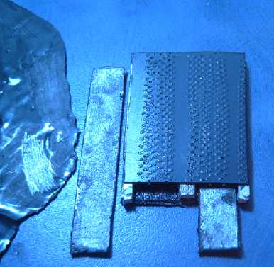 Well... If the
back wall was also the battery wall it would help... assuming
the battery was to be only 2 electrodes wide. To have more electrodes
in the middle, they might be made double width with perforated faces on
both sides: 2.5g*2 (perf faces) + 5g (thicker frames) + 2*2g (graphite
bars) = 14g again, but for twice as much electrode, 6 or 8 grams worth.
They'd have to be filled very carefully, compacting a little electrode
substance on each side of the graphite alternately. Thinner graphite
bars would help. So would injection molded parts, which could have thin
frames that would put the pockets closer together with little waste
space and minimal material.
Well... If the
back wall was also the battery wall it would help... assuming
the battery was to be only 2 electrodes wide. To have more electrodes
in the middle, they might be made double width with perforated faces on
both sides: 2.5g*2 (perf faces) + 5g (thicker frames) + 2*2g (graphite
bars) = 14g again, but for twice as much electrode, 6 or 8 grams worth.
They'd have to be filled very carefully, compacting a little electrode
substance on each side of the graphite alternately. Thinner graphite
bars would help. So would injection molded parts, which could have thin
frames that would put the pockets closer together with little waste
space and minimal material.
Possibly I could also try conductive plastic for the
backs, the fronts, the frames, or have conductive plastic bars instead
of graphite.
There has to be a good answer out there somewhere. In
1897, alkaline cells almost went by the wayside until Waldemar Jungner
tried every metal to see if anything wouldn't corrode away and found
that nickel (and only nickel) had some strange immunity to anodic
(positrode) corrosion in strong alkaline solution (but not in weaker or
neutral solution).
Only graphite (or "carbon black" if I found a source of
it) seems to work in weaker alkalinity, and it would seem to be just a
matter of finding a stable, practical and economical form of it, or of
graphited plastic that has low resistance. If this can be found, it
should make KOH alkaline cells cheaper too, since the nickel presently
used has become rather costly even just for plating. (Canada quit
making nickel nickels 30 years ago.)
http://www.TurquoiseEnergy.com
Victoria BC