Turquoise Energy Newsletter #52
Turquoise
Energy Ltd. News #52
Victoria BC
Copyright 2012 Craig Carmichael - June 2nd, 2012
http://www.TurquoiseEnergy.com
= http://www.ElectricHubcap.com
= http://www.ElectricWeel.com
New: Solar 'grid or no grid' Home Electricity
Project
Month In Brief (Summaries)
- web site - new Hubcap motor; outboard motor (construction delayed
by trying to get CAD/CAM software going... is it worth it?) - Turquoise
Battery development - Making small scale home solar more practical
In Passing (Miscellaneous topics
and editorial comments)
- Dept. of Progress = Dept. of Patent Administration? - A Sodium
Sulfate/PbPb acid battery report - Solectria electric car -
Google search "spying" and search
results "censorship", and a
better, private, search engine (ixquick.com)
- European cars get better
mileage? - France's new president
Hollande...
a real leader? - International finance: a house of cards -
Homelessness amidst a nearly static population and an adequate supply
of housing?
Electric Hubcap System
* New motor, outboard(s)
* Sprint NiMH battery box
* Rotor rim case mold troublesome - improved technique & material
should help rather than new mold
* How much power? - to run a car
Planetary Gear Torque Converter
Project
* No power is lost by the slipping gear
* Motor/generator with microcontroller control as slip control
* A more ideal planetary gear for torque converters?: large surface
areas, self lube plastic...
* Other types of three element gears would also work: eg, differential
gear
* Review of some other potential types of torque converters (now mostly
redundant)
* Torque converter for Sprint
car: - shift/tension clutch lever
Magnetic Motion Devices
* Temperature drop tests: results negative but inconclusive so far
Solar Electricity Project
* Why? - save energy, cost; grid independence
* How? - The "DC Grid Tie" - electricity grid or no grid, sunshine or
no sunshine
* What? - are good loads to connect - Hot water preheater "dump load"
to utilize any surplus energy
Turquoise
Battery Project
* Positrode current collectors with grafpoxied carbon fiber (best yet,
I expect)
* Simplest zinc electroplating
* MnZn sintered electrodes - brittle but high current - trouble with
using
MnO2 as the Mn
* pure Zn strip current collectors & better Mn pocket negatrodes
* Are 3-D printers ideally suited to make ABS electrode baskets?
No Project Reports on: Weel motor, LED Lighting Project, DSSC
solar cells, Pulsejet steel
plate cutter
Newsletters
Index/Highlights: http://www.TurquoiseEnergy.com/news/index.html
Construction Manuals and information:
-
Electric Hubcap Motor - Turquoise Motor
Controller - 36 Volt Electric
Fan-Heater
- Nanocrystalline glass to enhance Solar
Cell performance - Ersatz 'powder coating' home process for
protecting/painting metal
Products Catalog:
- Electric Hubcap Motor Kit
- Sodium Sulfate - Lead-Acid battery longevity/renewal
- NiMH Handy Battery Sticks, Dry Cells
- LED Light Fixtures
Motor Building
Workshops
...all at: http://www.TurquoiseEnergy.com/
(orders: e-mail craig@saers.com)
May in Brief
I had some visitors, some computer problems and some yard
work to do in May and got less done than I hoped to.
On May 4th I published the April news report, and moved
all the newsletters to my safer www.saers.com/recorder/craig/
site (changed this year from www.saers.com/~craig), hopefully for
posterity, most kindly hosted by fellow recorder (the flute) music
enthusiast
Niklas Saers and the Saers family.
From then to the 9th I vacillated about what I was doing
and did bits of work on a test for thermomagnetism, a new Hubcap motor,
positrode current collector experiments for
MnO4-Mn batteries, and the torque converter for the Sprint car. And a
new design of magnet machine emerged. On the 10th I got my SR & ED
tax credit for 2011 and payed off my debts.
On the 12th, I made a large wood box sized to enclose NiMH
battery sticks in the Sprint car where the radiator was and the space
behind
that. Most of what was happening for the Sprint was being included
under other titles, and battery boxes hardly seemed worthy of the "NiMH
Battery Project" title, so I decided to drop the "Sprint Car Conversion
Project" and "NiMH Batteries" headings and put everything under other
specific headings like "Torque Converter" or into the broad heading,
"Electric Hubcap System".
Trying to find an easier way to
create G-code for hole drilling of the new motor, I didn't get it done
at all. Finally at the end of the month, I realized I could simply
enter the exact G-code text as well as the calculations into a
spreadsheet and extract a finished drill sequence, with no special
CAD/CAM software or anything.
Later in the month I made a
sintered manganese electrode
with powdered zinc for a conductive 'sponge' and zinc coated aluminum
grille and leed wire, which was tried on the 22nd.
In doing so I found on the web a great way to do zinc
electroplating with common household ingredients.
(See Turquoise Battery Project heading.)
However, with zinc as a substrate and using
"overdischarged"
MnO2 as the manganese, I had created
a sort of a shorted out MnO2-Zn battery, and the MnO2 oxidized the
zinc. This
left exposed aluminum, which dissolves in alkaline electrolyte, and the
leed dissolved though and fell off in a day. This is probably why the
galvanized nails and bolts used earlier also seemed to not work - in
each case, I think the second electrode post I inserted worked:
because the manganese was by then "discharged" (disoverdischarged?) to
Mn(OH)2.
I studied potential ways and means on the web. It seems
that if MnCO3 is heated to 300+ºC in a closed tube (to keep out
excess oxygen), it'll drive off CO2 and become MnO - unhydrated
Mn(OH)2. That won't oxidize the zinc. Since the sintering requires
heating the electrode above ~450º anyway, it seemed a good fit,
and I bought some manganese carbonate at the pottery supply.
Before it quit, I got some great current readings in load
tests with Ni-Mn in what had been a Changhong Ni-Fe cell in KOH. The
cell
overall was at
least 10 times as conductive as the original Ni-Fe. For the first time
in the whole project, one of my electrodes had conductivity high enough
for demanding
electric transport applications without employing an unreasonable
number of batteries. If the promising positrode current collector
experiments with grafpoxied carbon fiber also work
out well, there should be practical DIY cells.
Sizing up the panels for the "DC Grid Tie" solar project
Near the end of
the month, worrisome international financial news got me thinking
about energy independence. Solar PV
collectors seem the best way to make electricity unless perhaps I get a
working
magnet
machine going. (Even then it would have to be a good size to match the
output of solar collectors.) But how is the
energy generated to be utilized, in a way that provides electricity if
the grid is down? I decided to
expand on the idea of a one-way, low voltage "DC Grid Tie" to supply
power from the collectors and batteries until the voltage drops too
low, then the grid power will automatically handle the load - unless
it's down. Individual
inverters might run things like the fridge, and perhaps excess
collected
energy could be channeled into an electric water preheater tank so
nothing goes to waste. I
think there's potentially a whole range of salable "DC Grid Tie"
products here that
could make small scale home
solar much more practical.
In a closely related area, I didn't do anything on the LED
lighting. You'd think that with what looks like salable products I'd
have been onto this months ago. I have a bunch of emitters, but I
haven't even finished the last few lights that I commonly use in my own
house, and a couple of rooms could certainly stand to be brighter.
Finally, I considered how "Month in Brief" keeps getting
longer with items and editorials sometimes not directly related to the
energy
projects. This month there's more than usual, and I decided to make a
new heading for them, "In Passing".
"Month in Brief" goes backs to being relatively brief.
In Passing
Incidental news, editorials
- A Sodium Sulfate/PbPb battery report
- Department of Progress = Department of Patent Administration?
- May VEVA: Solectria car; power bicycle
- search
results "censorship" and ixquick.com
search to keep your private info private
- European cars get better mileage than North American?
- France elects...
a real leader?
- International finance: a house of cards
- Homelessness amidst an adequate supply of housing?
A reader reports that he made a solar panel system and
used 4 'NG-31, deep cycle' batteries that 'get drained most days (to
~42 volts)' and recharged 'to ~54'. He saw my sodium sulfate page and
put some in when they were new. They're now two years old and have
worked through all that in hot and cold weather in a shed. For daily
cycling, that would mean 730 charge/discharge cycles, from batteries
that are probably rated for about 120 cycles without the salt.
Depending on actual operating conditions - loads, discharge levels and
recharges - that's a 6 times improvement, and they're still going.
(Keep this quiet - the battery companies don't want people to know.)
A thought occurs to me, that my proposed Department of
Progress might instead be designated the
Department of Patent Administration.
No change of function is proposed, but it has that officious sound that
might appeal more to those in power, and remind that the department's
revenue would come from holding patents and collecting invention
royalties on behalf of inventors. It would still want to support
inventors and ensure they had resources to work with to foster a
continuing flow of new products and technologies. The department would
be keen to
find levels of royalties that would (a) encourage invention (b) not
restrict exploitation of new technologies and thus (c) maximize its own
revenues and value to the government. If Canada were to inaugurate this
department, whatever its name, I predict that soon American inventors
would be taking out Canadian patents instead of the other way around.
The VEVA electric transport meetings were moved to the 1st
Wednesday of each month instead of the 3rd. At the May meeting was a
1996 Solectria, one of about 400 made with GM bodies (Geo Metro?). It
was re-outfitted with lithium batteries instead of the original
lead-acid. It ran great, quiet, and had apparently been driven all the
way from Duncan to put in its appearance at the meeting. Assuming he
was driving it back over the Malahat mountain to Duncan that evening,
it apparently had very substantial range. The owner bought it for
10000$, half the original cost of the batteries. The previous owner had
moved up to a new Nissan Leaf or something.
Someone also brought a "souped up" electric bicycle and I
got to ride it around the parking lot (my first ever electric bicycle
ride, in fact.) The performance was astounding, and I wasn't surprised
to hear it was 1.7 KW.
Did you know that Google Search stores considerable
information
about you? I've been suspicious of them for some time. Evidently it's
the world's biggest database of potentially very personal
information on everyone - and it gives different people different
results for the same
search term. It tries to tailor your results to... to what? (a) what it
thinks
you want to find, or as it often seems to me when I search (b) what it
thinks commercial
interests who advertise with Google would prefer you to find. Either
way,
it may be eliminating things you should be finding, and if someone gets
curious about you (eg, if you some day become a public figure), all the
websites you've ever been to could potentially come back to haunt you.
Someone told me about an internet search engine I hadn't
heard of before,
ixquick.com,
"The world's most private search engine", that simply searches the web
for what you ask for - like Google and all the others used
to do. They specifically go to great lengths not to acquire and record
information about users, and only put the search preferences you
selected and wanted saved (like giving 50 or 100 results instead of a
measly 10)
in one anonymous cookie on your own computer - no tracking cookies. I
am delighted to find
there's such a search engine!
Someone posted a video saying he'd been to Europe and
rented a car there. The European Volkswagon Passat apparently gets 78
MPG where the USA version gets 40-something. He tried to buy the
European version on return but the dealer said that although they were
made in the USA, they couldn't sell them there. Evidently the
'emissions per gallon' were too high to meet US EPA standards. However,
because it used less fuel, the emissions per mile were lower.
It has also been said that the European version has poorer
acceleration. Evidently the European version was probably a diesel,
which generally does do better than gas. It still begs the question of
why the diesels aren't available here - people go to the car lot
wanting to do the right thing, but the existing more fuel efficient
models aren't there. One friend raves about his old VW diesel pickup
truck that gets 65 MPG, but it was one of only a few ever sold in N.
America. Governments use gasoline taxes to fund things, and
instead of finding more creative means, it would seem they simply abet
the
petroleum companies in helping us to maximize fossil fuel
usage, the mentally slothful choice, robbing the future and racing us
down the highway toward extinction.
Of course, a real solution at least for the short term is
to save petroleum or diesel
burning for long trips and use other power sources like economical,
high energy batteries for short ones... that of course is what my new
battery chemies and long running motor project are for.
On youtube I listened (with my meager French) to
the victory speech of
Francois Hollande, France's new president, narrowly elected about May
7th. It was
like a breath of fresh air: He first said he was elected to serve
France, all France (including those who didn't vote for him) -- where
increasingly most politicians seem to think they've been elected to dictate,
to impose their will on the populace, ignoring their own election
promises and the protests of the people. (This is one reason citizens
need to be able to initiate referendums, reasonably easily, which right
has pretty much eluded us in Canada so far.) We might consider a bit of
Urantia Book philosophy: "That government is best which governs least
while co-ordinating the most."
Hollande said his focus would be on
equality, justice and youth. "It's all for the youth." Whatever made
Frenchmen more equal - including more equitable distribution of wealth
- would be his socialist priority. A speech remains to be proven by
actions, and adverse forces may hinder or block the best intentions,
but I had the impression that
France has elected a real leader instead of just a manager or (worse) a
stoogie for commercial vested interests.
From other things I've heard he
evidently wants to quit using American dollars as a trading standard
(as the BRIC countries and others are already doing). He may take
France off the Euro currency owing to its problems. (I remember a
British PM (John Major?) saying Britain was sticking with its Pound
currency owing to "serious flaws" in the conception of the Euro. Those
flaws seem to be coming to the surface.)
Evidently there's also a new currency - IIRC it was called "Virtual
Coin" - which has appeared on the internet, which isn't under the
control
of any nationality. I didn't really check into it, but it seems to be
more than just a silly idea.
If you don't know what the "BRIC" countries are, you've
probably been watching too much North American news. I first looked up
RT
Times, and later Pepe Escobar or Max Keiser (and I'm still branching
out) on youtube, and I found a world of journalism with international
viewpoints,
insights and focuses, sometimes discussing underlying forces, hidden
agendas and motives and providing broader, more international insights
into the events and pressures in the world. Things aren't always as
they're painted out to be in the daily TV news. (Consider the tardy,
biased coverage of America's biggest story, Occupy Wall Street. And
when did you find out that the US president can, since January, sign
something to put anyone away, without even accusing them of a crime,
much less without a trial? The rule of law is gone there. The obvious
next step is dictatorship.)
A considerable part
of the reporting was about, or led me to read things about, finance and
the money system, which is Keiser's specialty. The way it works today,
it seems banks bring "money" into the system whenever someone takes out
a loan.
This develops because they're allowed to loan more money than they
actually
have, since normally no more than a fraction of the loans ever have to
be payed out at once. (If you or I loaned money we didn't have, we'd go
to jail.) Then the borrower has to pay the bank interest with real
money
on this money that never existed. So in fact, the banks bring more and
more debt into the system. Of course, people and governments who borrow
more
and more contribute to the problem. The
end result is there's far more money owed than there is actual money.
It's impossible that the debts can ever be paid off - they just get
bigger and bigger. Around the world, the whole house of cards seems to
be near the point of collapse. Along with all the R & D items, I
finally went out and bought some 1 oz silver coins to buy groceries
with in the event that paper money becomes unstable. (Hopefully by
then, if it happens, I won't be in the market for much gasoline.) At
worst, silver isn't likely to go down much, and investors all say to
diversify. I also found that the dysprosium I bought in 2008 for
battery research and didn't use is presently worth much more than I
paid for it - an unintended 'precious' metal investment. I'm selling it
to pay for solar collectors.
And some of the reporting got me thinking about
homelessness... One
thinks of all the work that goes into making a dwelling, and thinks,
well, isn't it right that someone buying one to live in should pay for
all that? But a house can stand for 100 years or more (mine is over
130), and someone may only live in it for 1, 5, 20 or 50 years. Is it
right that each new owner should pay for all the work the house
initially represented, over and over? When they also pay for the
upkeep? Homes used to stay in families for generations, and each new
generation inherited it. They didn't have to buy it over again.
As population swelled, towns and cities grew, there
weren't enough houses, and in effect each new generation did have to
buy all the work of building to get a house, especially a new one. Yet
here we are now with a leveling population, to start dropping sometime
around 2035-2055, yet more and more people are homeless. At the same
time, a few individuals own more and more dwellings or land as
investments, and some of them are empty. Why shouldn't people who need
homes have them if there are enough for everyone?
One solution, rather dictatorial, would be to simply
forbid owning more accommodations than a person or family can be
reasonably expected to make use of, or more land than seems reasonable
for a farm, eg, limit everyone to owning no more than a square mile or
whatever and stop huge
operations (and a few wealthy individuals) from monopolizing ever
vaster tracts of land. That would
estate-enfranchise far more people than the number who would be
marginally inconvenienced by having to
sell off their multiple holdings.
Another solution (put simply) would be to allow one
(reasonable) dwelling unit as a primary residence with no tax. The
second unit, or farm land in excess of some maximum, would be taxed at
the going rate. The same owner holding a third property would have it
taxed at 1.5 times the rate, the fourth unit at double, the fifth at
2.5 times, and so on. Holding real estate in great excess of personal,
family, corporate or farm needs would simply become a poor investment,
and if the greedy insist on tying up houses and land they don't need,
they can at least pay for the privilege.
Electric Hubcap Motor System
Outboard(s) & Motor for it
First a side note: Since I found the excessive gear noise
of the previous incarnation was from the motor pushing down hard on the
shaft and wasn't an intrinsic problem, I think that for an outboard
from scratch I'll go for the traditional shaft and right angle
gears rather than either chain or belt drive. I've seen 45º angle
gears available that are used to get a 90º angle, and they always
have 1 to 1 ratio, solving the problem for higher speed boats of the
unwanted speed reduction in gas outboard feet. An aluminum or stainless
steel angle iron piece might hold the bearings and align the gears. The
electric of course needs no gear shifting for neutral and reverse.
On the 11th I thought I should get
going on the outboard motor for the salmon boat. I decided to use the
Honda again since the system wouldn't be for high speed travel.
However, I got bogged down in trying to use CAD to get the positions
for the bolt and ventilation holes, and although I did some more work,
things mostly ground to an unintended halt. I didn't finish making the
motor, let alone get it mounted in the outboard.
As the rotor and stator are
reversed from the old motor, the shaft needed a shaft key in a
different spot. I tried to
make a key slot in the [car transmission] shaft with the square end
that I made in 2010, but the steel was so hard it took two milling bits
on the lathe to make a short slot, breaking the first one and dulling
them both. I'll use a short key. I resharpened the second (brand new)
mill, but whether it'll work well again is doubtful. I wish I had at
least roughed out the slot with the angle grinder. That's how I did the
slot the first time, before I figured out how to do the milling.
But it didn't seem the motor would fit under the hood. On
the 23rd I finally decided to see if I could put a U-joint in the shaft
and put the motor in lower, at an angle. It might just make it. The
next
day I bought a U-joint coupling for 1/2" socket wrenches. Now I'll be
using a different shaft from the one so painstakingly prepared.
Sprint Battery Box
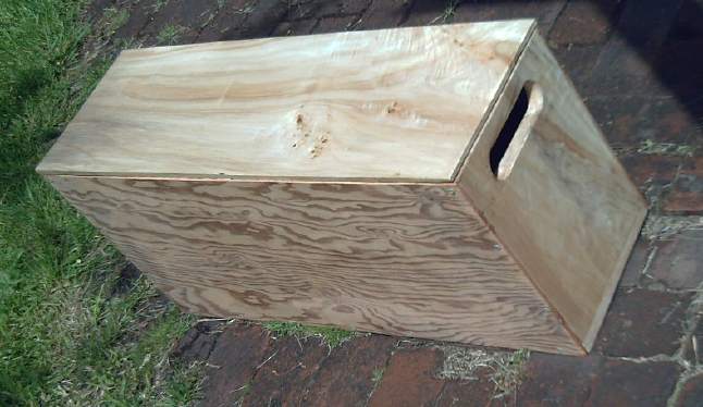 I had
envisioned mounting the batteries for the Sprint
in some sort of racks where the radiator used to be. Now I decided that
an open frame
mounting was probably not a good idea. Better to have the many contacts
enclosed in a box, as shorts would be dangerous. So I essentially
copied the idea of the wooden box I recently made for the motorcycle,
but long enough to lay 12 volt (2' long) battery sticks in
horizontally. I'm not quite sure how I could conceive of putting
gorgeous figured lombardy poplar together with used 1/4" degrade fir
plywood.
I had
envisioned mounting the batteries for the Sprint
in some sort of racks where the radiator used to be. Now I decided that
an open frame
mounting was probably not a good idea. Better to have the many contacts
enclosed in a box, as shorts would be dangerous. So I essentially
copied the idea of the wooden box I recently made for the motorcycle,
but long enough to lay 12 volt (2' long) battery sticks in
horizontally. I'm not quite sure how I could conceive of putting
gorgeous figured lombardy poplar together with used 1/4" degrade fir
plywood.
I cut the pieces to the maximum size that would fit in the
space: 9" deep by 13" tall by 28.25" long, with a figured lombardy
poplar top. That let it fit 12 volt
handy battery sticks arranged as:
* 4 rows of up to 7 columns tall (28 - 280 D cells, 3360 WH) with
styrofoam padding on the sides
* 5 rows of up to 7 columns (35 - 350 D cells, 4200 WH) with no padding
* 3 super battery sticks with 4 handy battery sticks beside each one in
a skewed arrangement (33 - 330 D cells, 3960 WH)
(Yikes - it could weigh up to 150 pounds with so many
batteries!) These storage figures should be good for local driving
range - not a lot more. I don't know yet how low I can get the WH/km
figure. They're also more D cells than all I have so far. I ordered 50
more on May 11th. They were "on sale" at 12% off. Impulse shopping.
A minimal setup for general testing would be 15 sticks, 5
parallel sets of 3 in series, since 3 gives 36 volts, and 30amps * 5 =
150 amps (max. continuous), while the maximum motor draw is under 150.
(As far as range, that should at least get to the grocery and back.)
An 'extra' stick or two will go on the lowest 12 volt
section, in preference to having a separate 12V battery for the lights
et al. The mostly LED lights don't use much power, and as I'm charging
each 12V section
separately, the arrangement raises no charging issues except that the
lower 12V section might take just a bit longer to 'top up' than the
other two. Big deal.
Terminals will be provided for ground, +12V and +36V.
Three APP 30 amp charging plugs to mate with the 5 amp power adapter
chargers will be on one end. Hmm... for 100 AH, it could take up to a
day to charge at just 5 amps. Oh well!
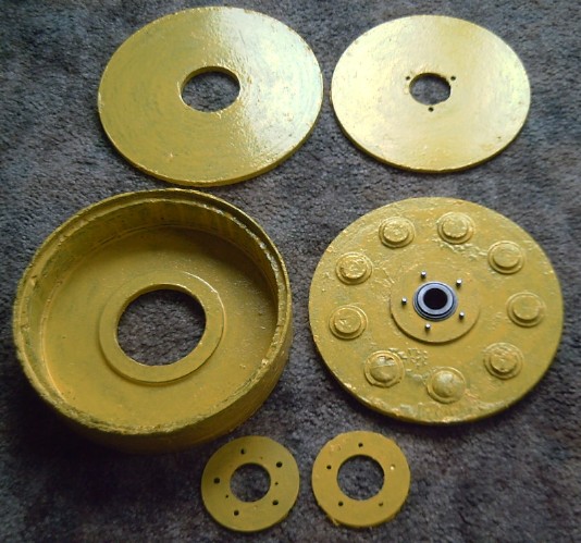
New Hubcap Motor - Rotor rim case mold & molding
L: Stator end with coil cores
R: Middle (coil top 'buttons'), and rotor compartment.
 I'm not happy with the
rotor rim mold, which I used
"properly" for the first time. The result was less than beautiful, and
it took me a whole day of fiddling around and touching up after the
initial molding to finish it. Spending that kind of time on one piece
is counterproductive. However, the remedy may not be a new mold but
improved technique.
I'm not happy with the
rotor rim mold, which I used
"properly" for the first time. The result was less than beautiful, and
it took me a whole day of fiddling around and touching up after the
initial molding to finish it. Spending that kind of time on one piece
is counterproductive. However, the remedy may not be a new mold but
improved technique.
One thing I was sure was needed was 2-1/2" wide PP
strapping,
which I hadn't found to buy yet. That would give it a smooth one piece
outer skin. Three layers/winds of it would give that plus a uniform
upper tab to keep the end cover centered. If I also found 1-3/4" wide,
I could put an inner skin on it. If not, I could cut 2" down to 1-3/4"
with scissors. Finding 2-1/2" strapping was key, however. I've seen it:
in light colors in aluminum frame patio furniture. Buying it alone has
proven to be another matter.
Given the strapping, there'd be just a thin interior left
to stuff PP cloth strips into to finish up. The sides of the mold would
hold the strapping straight and rigid. Small gaps in the fill would be
unimportant and also unseen.
On the 16th I found 3" PP strapping at a tent & awning
place. It went from 2" to 3". But 3" can be trimmed down, so with a
certain amount of aggravation, it solves the problem.
Instead of spray paint, I found polyurethane enamel in 1 litre tins. I
figured that would make a much thicker coating, so I bought it. Of
course, paintbrush isn't as beautiful as spray. And when I bought it, I
was thinking yellow would be a good rotor color, not about the case
color. But I'm certainly not changing back until the 70$ tin is empty,
if at all!
While on the subject of the new motor, here are the
pictures I took at the beginning of May for the motor making manual,
showing the epoxying of the magnets onto the rotor:
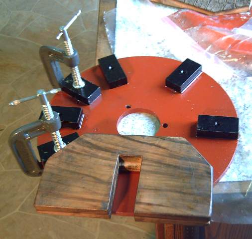
The first six magnets are easy. The placement jig sets the spacing and
alignment.
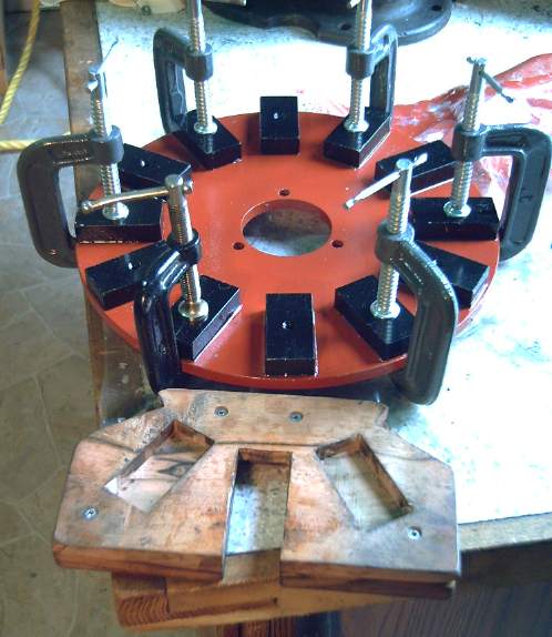
The second six want to glom onto the other magnets and must be clamped
down before the jig is removed.
All twelve magnets must be the correct way up for the motor to work
right: NNSSNNSSNNSS.
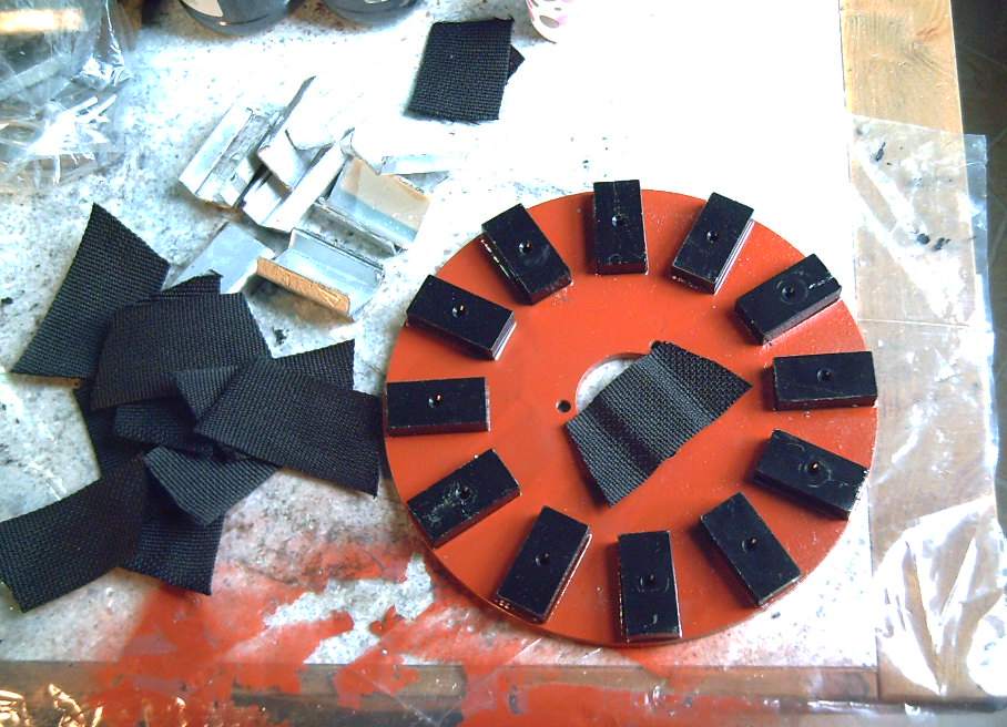
About to start putting the polypropylene strapping onto the magnets.
(I took more pictures. Where did the rest go?)
How Much Power?
I found a site with some 'typical' EV conversion motor
power figures (below) and
thought it
might be nice to compare estimates, with a ~2400 pound car like the
Tercel, but with the 33% less for the anticipated efficiency gain with
the torque converter instead of a transmission.
I'll start with my main conclusion: With the torque
converter offering infinite reduction ranges and a single 5 KW Electric
Hubcap motor, one might expect a small car to make quite a zippy start
from a stop, but with performance dropping off with vehicle speed. It
should be adequate around town, but probably not on a highway unless
it's pretty level with few starts and stops. (Ie, not on our
mountainous
BC highways, and it's likely to be sluggish regaining highway speed
after a stop.)
The rest of this section is just tedious details.
To do 50 MPH/80 KmPH we use their estimating equations otherwise as-is.
These
show that two Hubcap motors would be required for good highway
performance. This isn't unexpected.
[1 HP/1000# @ 2400# = 2.4 HP] + [Cd of .3 = 3 HP] + [2% grade, 4.8 HP]
= 10.2 HP.
Driving around town takes less, and the add-on motor that allows
switching to gas on the highway gives the flexibility to avoid needing
that 10 HP of electric power. Assume 55 Km/H is the max, and that
above that you would switch to gas. Estimate of rolling and hill
climbing resistance would be about 2/3 of highway speeds, and wind
resistance would be half.
[1.6 HP] + [1.5 HP] + [3.2 HP] = 6.4 HP.
This is still a little above our nominal 5 HP rating. What it would
mean is
somewhat slow hill climbing and acceleration at street speeds. Some
slow-down on steep hills is common for gas cars anyway.
I may up
the amps settings a bit in the controllers and allow up to maybe 160
amps,
which would be 5760 watts, well over 5HP. Above 100 amps I get more and
more nervous about the controller and about motor heat. On the other
hand, I haven't tried and it might be found that higher figures pose no
problem at all.
To estimate for the Sprint, I'll simply call it 2/3 of the above,
since it's only 2/3 as heavy: Highway 6.8 HP, City 4.3 HP. Conclusion
is it should perform pretty well around town, probably even on level
highway. (Avoid Malahat Mountain!) Probably to get these favorable
results, I
should
replace the chain drive with a belt.
(Note: I've neglected to add the weight of the motor and batteries to
the vehicle in these calculations.)
The
basic equation for determining the hp required for a drive system is:
Required Hp = Hp (Rolling Resistance) + Hp (drag) + Hp
(Hill Climbing) + Hp (acceleration)
- Rolling
resistance is typically 1% of the vehicle weight. It takes ~1.5
hp per
1000 lbs of vehicle to maintain 50 mph at 0% grade and no aerodynamic
drag. So a 4000 lbs vehicle is 4 times as much ~ 6 hp for rolling
resistance.
- Aerodynamic
Drag is a function of speed squared and frontal area. If you
double
the speed, the aerodynamic drag increases by 4! With a Drag
Coefficient of 0.2 (Cd=0.2) very aerodynamic vehicle, is approximately
0.7 hp at 25 mph and approximately 3 hp is required at 50 mph. With
Cd=.4 approximately 7 hp is required at 50 mph. This is based on a
frontal area of about 18 sq ft.
- Hills are a major obstacle. A 1% grade is a 1 ft rise in
100 ft. This is
the same amount of energy as rolling resistance. A 5% grade (5 ft
rise
in 100 ft) is five time rolling resistance. That means that it
takes 5
times rolling resistance (~8 hp) for a 1000 lb vehicle. For a
4000 lb
vehicle, 30 hp is required for the same 5% grade. This is why
designing a vehicle for Colorado is considerably different than
designing an EV for Florida.
Typically, when we size motors for on-road EV applications, we assume a
2% grade
and 50 mph. For a 4000 lb conversion, this would be another 12 hp for a
total of 25 hp. Our rule of thumb has been it takes 6- 8 hp per
1000
lbs. That would dictate 24-32 hp. You can see that we
are within the
range.
- Acceleration
can become the dominant requirement. Looking at the totals above
for a
4000 lb vehicle with a Cd=.4, approximately only 13 hp is required
to
maintain 50 mph and 0% grade. A Corvette requires ~ 20 hp at 60
mph
and 0% grade. With a 430 hp engine, acceleration is the
predominant
requirement for the 2010 Corvette.
Planetary Gear Torque
Converter Project
No power is lost in the slip
This is a bit tricky to figure out, but it is of course a
very important point.
Ignoring friction
etc, one's first thought would be that if the slipping gear is going
1/2
speed and the drive gear is also going 1/2 speed, 50% of the power is
going into the slipping gear. But this isn't true. The slip
gear isn't an inert
load - without restraint, it wants to go full speed rather than to stay
stopped, and when it does, no power is transmitted at all. If the slip
gear is stopped, all the power is being transmitted to the drive gear,
so again no power is being lost. If it has a controlled slip, the motor
uses less power to maintain the same speed by the amount of the slip.
Thus it takes no power to hold it stopped or
to let it slip - freely or any amount. All the power that the motor
puts out goes to the drive shaft.
Only if the slip gear is
pushed in the
opposite to the slip direction does it take
power to turn it. In that case, which isn't part of normal operation,
it would be doing work. It would then be similar to a car wheel
differential, where
some of the power goes to each wheel. And the car differential is
similar to
the torque converter when
one wheel is slipping in the mud: no power is needed except
to overcome the weak friction, and stepping on the gas even a little
will just rev
up the engine and wheel and splatter the hapless
pushing volunteers with mud.
Thus, if the slip gear is turning 1/2 speed, it's losing
no power, but the speed of the drive gear is cut in half. Power =
Torque * Speed, so the motor can turn with the double the speed,
and the torque is doubled for the same output speed. From another
perspective: for a
given torque, power needed drops as the variable reduction ratio is
increased. A puny motor could slowly move the car.
Except for frictional losses, all the motor's power is
being
transmitted to the driveshaft, at any gear ratio.
Motor-generator with microcontroller as slip gear control
Someone mentioned new car variable transmissions and said
they used a motor under microcontroller control to control a shaft
turning rate that controls the reduction ratio. I couldn't find much
info. While it's possible the car manufacturers have figured out the
planetary gear's torque converter potential, I've found no mention of
it. I suspect rather that they've found needlessly intricate ways of
doing much the same thing, as shown in a recent patent (see 'other
types of torque converters' below).
However, the idea of using a motor and microcontroller
might be a good one, considering that the various mechanical means of
control
look trickier than expected. The slippy rope "clutch" around the V-belt
pulley could be replaced by a V-belt going to the control motor. The
microcontroller would monitor main motor RPM, current, electron pedal
position, and vehicle speed, and decide how much slip would be best.
The slip control motor presumably would take very little
power, since it only holds back the slippage. It might even generate a
bit.
A more ideal planetary gear for torque converters
My thought is that a physically large, very wide planetary
gear with aluminum sun and ring gears, and self-lubricating plastic
planet gears, would be more ideal than the typical steel planetary gear
with case hardened teeth seen today. It could be used without
lubrication, with the large contact surfaces spreading the load and
heat to run cool. That way, no oil bath, oil drip or frequent
greasing would be necessary.
I've seen aluminum gear teeth (for a timing belt type
pulley) being cut on a homemade CNC lathe with a "flying cutter" in a
drill chuck, so it's doable. (The inside of the ring gear might be
tricky. ...Or, I may yet have a good use for Camosun College's VICAMP
facility with their 3-D plastic fabrication machines.)
My ideas of "large" and "wide" are flexible. I'm starting
at maybe 5" diameter and 1.5" wide and going up to as much as 12"
diameter and 6" wide - whatever seems needed for reliability and long
life.
Other Three-element gears that could be torque converters:
differential gear
Other three-element gears besides planetary gears could
work. A
differential, for example, could have the left or right "wheel" gear as
the slip element, and the output drive would have a 90º angle from
the
input. An interesting feature is that with no slip, the ratio is
actually a speed increase (torque reduction) of 1 to 2. An amusing
thought is that I could have done this in the Sprint, giving a
one-wheel drive. It would have had to be always slipping to get the
needed ratios.
Or, right and left could be the (in line drive, anything:1
to 1:1
ratio) input and output, with the "drive" gear as the slip. This
probably could have been done with the Sprint and one wheel too, but in
this case the planetary gear with the 2.1 to 1 reduction is very
similar and more appropriate.
Other types of torque converters
While the planetary gear converter appears to be an
excellent type
of torque converter and I've decided to go with it, I'm not convinced
that there aren't other potential types of torque converters waiting to
be discovered or developed, so I think I'll summarize the ones I know
of or have thought of here.
I omit belt driven CVT types and a bizarre converter used
for bicycles that looked likely to be hard to scale up to car size.
There are also 2 or 3 (expired?) patents for torque converters. None
looked very promising to me. One was for bicycles, and I confess I
don't see how it could possibly work. (I'm not saying it doesn't. I
wrote a letter to the inventor but got no reply.)
A recent patent (WO2009039590) for a "CVT" comes from
Australia. Perhaps it has some advantage(s), but in essence, to me it
looks like he's created a complex converter
with several gears to do about what the planetary gear converter does.
From somewhere
I gather a microcontroller and a motor are used for computer controlled
"modulation" (slip) in some new car transmissions, which may or may not
be based on this design. This seems similar to the idea of putting a
generator on the slip gear, except for the computer control.
Constantinesco's oscillating masses converter (1923)
obviously worked well,
especially if two masses were used oscillating at 90º to each
other, which canceled out vibrations. He was making whole
transmissionless cars with such converters built into the two cylinder
engines by 1926. (They used 1/2 the gas of other cars.) After GM
tricked him into shutting down his car production, he used
them for railway locomotives in Eastern Europe into the
1930s.
The magnetic impulse type would have worked if the forces
had risen linearly with speed. They don't. As it is, with NdFeB
supermagnets and copper, it appears somewhat too much magnetic material
would be needed to be practical, and the reduction ratios attained will
be
small, eg, 3, 4 or
5 to 1, with considerable speeding up and slowing down of the motor as
it crosses the interaction zone.
Superconducting materials with very powerful fields and
interactions could change that picture, and 28ºC superconductors
have recently been identified. This type might especially become
practical if the fields
can be varied or switched on the fly, which could once again offer an
infinitely variable reduction ratio. Of course, motors using
superconductors might themselves have the torque to make torque
converters redundant.
My ratchet drive converter was proven to the point that
with a ratchet wrench on a nut on the car wheel axle, I could easily
move the car around by stepping on the horizontal handle of the wrench,
then ratcheting it back up to horizontal again. Since I weighed around
150 pounds and the handle was about 10" long, I was applying about 125
foot pounds of torque to the wheel.
However, the idea had several smaller but vexing
challenges. First was a limited range of reductions. Then it really
would need the motor mounted elsewhere than on the wheel, in order to
have a push-pull rod to the ratchet on the wheel axle. At least, I
couldn't think of a simple way to mount it on the wheel. Mounting it
elsewhere isn't necessarily bad, but it would have to be level with the
wheel to avoid problems with interactions with the vehicle's
suspension. I didn't really come up with a good place on my car. Then,
the car would only move one direction - no matter
how it was propelled - unless the ratchet could be reversed like a
socket wrench, or at least disengaged. (At least it couldn't roll
downhill if parked facing uphill.) The ratchet wrench I found that was
strong enough for the job didn't have that feature - to go the
other way you were supposed to turn it over.
Also notable is that the weights of the oscillating pieces would cause
vibration unless they had counterweights.
I had previously conceived of it with some centrifugal
mechanism on the motor to change the distance of the drive pin from the
axle to alter the reduction ratio. I didn't come up with a satisfactory
idea for making this either.
Recently I had the thought that instead, there could be a sliding
control on the ratchet side, perhaps operated by the driver through a
shift mechanism attached to a cable. Shaft/slide projections and
detents would prevent shifting during the power stroke.
Still there's the nagging suspicion that if all those
details were taken care of, the ratchet or one-way bushing would wear
out quickly with continual operation at hundreds of RPM. I mention the
design only for posterity, having figured out enough of the details
that it looks like it would work. (I did a drawing, but didn't bother
to take a foto.)
The "clock escapement" type converters - a variation of
oscillating masses - didn't get a car moving for me, but the car wheel
budged a bit with the last one every time the motor turned, suggesting
it was making 10 or 20
foot-pounds from a motor producing maybe 4-6. (motor controller problem
back then.) At the
time I had no means of measuring torque,
or of how much was in fact needed to move a car. I'm sure it had too
many
transitions per rotation loading the motor down, and I'm not convinced
the idea wouldn't work with the right configurations and escapement
masses for stronger, higher speed torque hits.
And I half made but didn't finish or try the centrifugal
clutch with the 45º angle bouncing/ratcheting "pads" hitting into
transverse slots in the outer rim. It has promise. A really nice wide
slotted outer rim - I'm thinking 3 to 6 inches wide slots on a 10 or 12
inch
diameter drum, and wide wedges to match, would reduce loading and
stress at each
point to levels where aluminum and plastic parts would work without
quickly wearing out.
These last two types again both provide infinitely
variable
reduction, down to 1 to 1. Note that the forces all need to be on axis
(radial) and balanced, or the motion product is mainly vibration. In
particular, any axial forces simply shake the entire unit and
motor.
If a system needs a gear and a
torque converter, perhaps it might as well be the single unit planetary
gear converter. For a system that doesn't otherwise need a gear, one of
these
other forms might be worth trying.
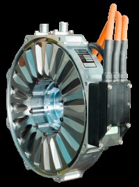 Then of course, if one makes a motor with enough torque, the torque
converter becomes at least somewhat redundant. I got a link to "Yasa"
motors. I assume this is the commercial development of the Oxford UK
axial flux
motors mentioned a couple of years(?) back. They're very impressive:
750 peak
newton-meters (566 foot-pounds. and there's a 400nm/295 ft-pd model),
and the efficiency is high.
Then of course, if one makes a motor with enough torque, the torque
converter becomes at least somewhat redundant. I got a link to "Yasa"
motors. I assume this is the commercial development of the Oxford UK
axial flux
motors mentioned a couple of years(?) back. They're very impressive:
750 peak
newton-meters (566 foot-pounds. and there's a 400nm/295 ft-pd model),
and the efficiency is high.
On the other hand, to get that torque, it
uses up to 100 KW at 700 volts and needs liquid cooling. With the
torque converter, the air
cooled Electric Hubcap at 5 KW and 36 volts will have almost unlimited starting torque, though it'll drop
much more rapidly with speed. I
know which one will make
a car go 0 to 60 MPH really fast and which one probably won't even hit
60 going uphill. I also know which one I'd rather work with, and buy
and charge batteries for.
With the torque converter, the 5KW will have almost
unlimited torque to get the car moving, still plenty at low speeds,
and overall, I expect, should perform decently at city speeds. Highway
trips need gas anyway unless the car is to be stuffed with batteries.
So far, it seems to me that's less economic, partly owing to the high
price of batteries.
Construction: Axle for Sun gear
On the 4th and 5th I turned
a (trailer stub) axle for a motor on the lathe, a fatter one with a
1-1/16" diameter end for the
sun gear of the torque converter. I used a carbide cutting bit that I
bought recently. It seemed to go considerably better than with steel
tools, but it wasn't a miracle cure. I had to sharpen it more than
once. The shafts I use for motors are of course pretty hard steel, and
it still doesn't pay to try to take off very much at once. If there was
water dripping on the tool point to cool it, things might go
considerably faster, because it was capable of taking off much bigger
shavings - until it overheated and quickly got dull.
Slip Gear Clutch Control
All the centrifugal or magnetic clutch arrangements I
thought of either
leave some slip even at high speeds or else create a 1 to 1 reduction
ratio instead of the design ratio of the gear. The magnetic ones might
allow too much slip based on experiences so far. So unless 1 to 1
(centrifugal type) is the
desired ratio, the manual clutch or brake for the slipping gear may may
in fact be the best of any reasonably simple arrangement. In the
Tercel, 2 to 1 makes 2000 RPM at 100 Km/hr on the highway (maybe 90 in
the Sprint with its smaller wheels), so that's about the minimum
desired
reduction ratio with the Electric Hubcap motors. Any less just reduces
power for no reason, from a motor that's certainly not oversized for
driving vehicles.
I think the best manual control would be a ratchet lever
like a parking brake - pull up to tighten, push the button and lower to
release. However, the parking brake on the Sprint is the only means of
holding the car stopped.
I decided to try the original gear shift lever as the
clutch tension control. (and I almost threw it out when I removed it!)
It's made, it fits the car, and it's in a good position to operate
while driving. "Park" (which won't hold the car stopped) is loose,
disengaged, and the successive stops are each stronger tension than the
previous for higher speeds:
P R N D L2L1 = O
1 2 3 4 5.
The stick gives the cable about 2 inches of motion. If
that's too much and it won't travel to 5 from loose in 0,
a stiff spring in the link will give it more give - and probably more
steady tension control.
I wanted to make it so that except for going from P,
the lever could be pulled back freely like a parking brake, but the
button would have to be pressed to go forward again so that it wouldn't
shift itself looser. But confronted by the existing logistick on the
6th, I
filed detents into 4 and 5, and bolted on a piece of
steel to make one between D(3) and N(2). The button now
has to be
pressed for all shifts except going from R(1) to N(2).
In the install, I also reconnected the key interlock so
the car won't turn on except in P. There was also an interlock
to prevent it from being shifted out of P unless the foot brake
was applied, but that's no longer desirable since pulling gradually
back on the stick from P with the foot on the 'gas' will be the
way to start the car
rolling.
Since I had mounted the F-N-R switch where the
shift lever was and had made that point a minor 'wiring central', on
reinstalling the
lever I had to relocate it and reroute the wiring. I
put the switch on the dash to the right of the ignition, and wondered
why I hadn't put it there in the first place.
Then I got caught up in other things and had to let this
project sit.
Magnetic Motion Devices
Magnet temperature drop tests:
results negative but not conclusive
On the 6th I decided to put together the test to see if
the temperature of a magnet dropped measurably when it was expending
energy. I rigged it up pretty fast with a hinge from "take 2" magnet
machine, a motor coil, and C-clamps and a vise. The first thing that
became apparent, while operating simply by touching and untouching the
wire to the battery, was that the wires were getting hot too quickly to
go on long. The coil was drawing quite a few amps to give sufficient
repulsion, and any small switch would have fried. I decided instead to
try rotating a permanent magnet with a small motor to alternately
attract and repel the target magnet.
A separate problem was that the meter read in unit degrees
C. If the temperature dropped perceptibly but less than 2 or 3 degrees,
the result would be uncertain. If it was less than a degree, I might
well not even know it had changed. The short test showed nothing
reliable, tho the meter went from 16 to 15 a couple of times during
operation. I would have to rig up something better.
So much for the quick test!
On the 10th I put my old wavepower gen rotor on an axle
and put it in a vise - 12 alternating polarity magnets. I again mounted
the flapping magnet from the
"take 2" design with C-clamps, so that when the rotor was spun by hand,
the arm flapped back and forth as the opposite polarity magnets went
by. I also wired up an AD590 temperature probe with a power adapter and
a 1K resistor so that 1 mV = 1ºK.
After a minute or so of turning, the magnet had dropped
about .2º. That looked promising, but it didn't drop more, and it
didn't seem to go back up while sitting at rest again. A subsequent
test showed no change. It certainly wasn't sufficient
evidence to validate the
theory - it seemed more to disprove it. A control sensor measuring room
temperature would have been helpful. Measuring the magnetsº on the
rotor might have shown something but would be hard to do. The test
setup was adequate to show larger scale results if they had presented
themselves, but not subtle ones.
I tried holding the magnet arm back with my hand to cause
it to resist the motion, and the magnet went up .5º after some
cranking. That seemed at least somewhat consistent with the theory, but
again it's a small rise could have other causes as well. Even the
proximity of my hand to the wires (an inch or more) might possibly have
heated
up the wires and hence the sensor by that amount.
 A surer way
would be to build a magnet machine that ran.
If
its magnets cooled down while running, it would be a pretty safe
conclusion that the energy came from the temperature; if not, vise
versa. Even if that were the case, I
suspect more and more that the force-energy that is
magnetism
must be derived from nuclear force-energies within the substance, and
that when magnetism does work, the energy is somehow being derived from
the energy within the atoms, whether an object is being moved once or
in a repeating cycle. Somehow it must be nuclear energy, available as
magnetism via electron flows without splitting atoms. And I'm by no
means thinking it's not thermonuclear at this point. Here we
come to the edge of known quantum
physics.
A surer way
would be to build a magnet machine that ran.
If
its magnets cooled down while running, it would be a pretty safe
conclusion that the energy came from the temperature; if not, vise
versa. Even if that were the case, I
suspect more and more that the force-energy that is
magnetism
must be derived from nuclear force-energies within the substance, and
that when magnetism does work, the energy is somehow being derived from
the energy within the atoms, whether an object is being moved once or
in a repeating cycle. Somehow it must be nuclear energy, available as
magnetism via electron flows without splitting atoms. And I'm by no
means thinking it's not thermonuclear at this point. Here we
come to the edge of known quantum
physics.
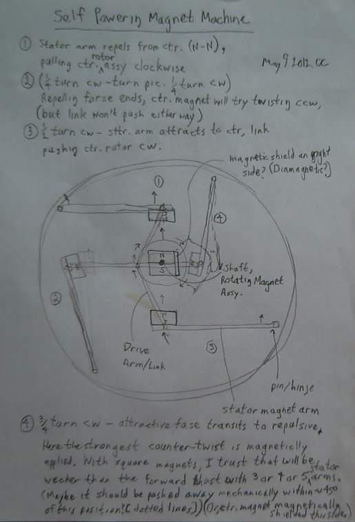
Magnet Machine Take 5
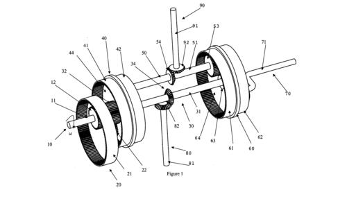
I drew a diagram of this new type on the 9th. I considered
that in just one position of the circle out of four the magnetic forces
would be contrary. But it was where the arm magnet was closest to the
rotor magnet, so the force would be strong. I considered having the
magnet rise vertically to be out of the field at that point, but that
looked mechanically difficult to do. Then I considered that if I offset
the center
magnet, it could be farther away at the contrary time and closer where
the twist was the right direction.
I really wanted some smaller, square profile magnets,
especially for the center magnet. Then it occurred to me simply to use
the magnets I had cut in half a while back, doubled up to make 1" x 1"
square instead of .5" x 1". No new money spent, and I got what I wanted
- square profile magnets that were weaker for safer handling.
Despite some difficulties with
structural strength versus magnetic pulling foreseen in the
construction, I decided to build it. But it takes longer to build
something
than to draw it, and I didn't get to it during May.
Solar Electricity Project
Why?
Solar panels have been dropping in price year by year.
Solar electricity became cheaper than nuclear in 2010, and according to
my calculations solar installations by BC Hydro would cost less than
their Site C Peace River dam project, with no flooding of land.
Some solar PV panel making companies have recently been
bankrupted by
the falling
prices. The price drop may continue more gradually, or at some point
(barring some technology breakthrough), gradually start to rise. I
suspect that
whenever the inclination strikes is probably a pretty good time for an
individual to invest in solar PV.
Individuals can make a huge dent in the total amount of
power needed
from the utilities by being more efficient, as with LED lights (and
electric cars that take less energy as I've been working on), and by
utilizing energy available on their own doorstep - solar, wind, flowing
water, waves, tides, geothermal or from waste heat as applicable. Solar
seems most practical for the most people.
But a solar system with a
grid tie inverter doesn't provide
independence from the power grid. If the grid goes down, the inverter
stops, so as not to electrocute linemen repairing the line. One might
also want independence from the grid in a mobile unit such as a camper
or a boat. In another situation, the "grid" may be replaced by a fossil
fuel burning generator or other device.
With only 1000 hours/year (out of 8766 hours in a year)
full sunlight equivalent in Victoria, electricity at 10¢/KWH, and
a 225 watt solar panel at around 500$ plus tax, panels
alone will take
20 years to pay for themselves - if the energy is being
effectively utilized. Without a grid tie to sell the energy to the grid
as it's made, reasonably full utilization of the energy and its
opposite, not running out of power when the energy is used up, are the
tricky parts. The energy generated has to either
be immediately used, or it must be stored. All I've been doing with my
one panel so far is charging 12 volt NiMH batteries and using them to
run LED lights or for motor tests. Most of the potential electricity is
going to
waste.
But if utilization can be attained with minimal investment
and maintenance, and if the work is mostly DIY by
the homeowner, there'd be the satisfaction of being more independent,
and of seeing smaller monthly power bills. And then, when the
inspiration and finances come together, or
if panels get cheaper or are found used or whatever, the system can be
gradually expanded to some optimum size. Some sort of system might
start (assuming all new equipment) as low as around 2000$, and expand
to 5000 or 10000$, with substantial savings off the monthly electric
bills, which might even be zero in the sunny months.
How?
The question then is how to make grid-independent small
scale solar
electricity accessible for everyday use in a practical and economical
way - to (1) fully utilize the collected energy and yet (2) not have
problems or inconveniences at the times when it runs out.
My key idea is to expand the one way "DC Grid Tie" idea
that I envisioned
earlier from 5 amps to 50 or more and adding some flexible options. It
would be a central wiring unit to replace more than one single purpose
unit.
One function would be a programmable or adjustable charge
controller with a maximum power point converter supplying voltage to
batteries. It might even incorporate two such units, optionally from
two sets of collectors, perhaps with different MPPt voltages, also
optionally supplying two banks of batteries, potentially even of
different voltages.
Connecting loads to the Tie allows it to solve problem
one: to utilize the solar energy, as it's generated or stored in the
batteries. (An idea for ensuring all of it gets used follows.)
The one-way DC tie-in to the grid solves the second
problem: if the solar energy runs dry, the regular house power simply
takes over. This might operate off a heavy duty battery charger, for
example. The intent is not (necessarily) that it charge the batteries,
but that it runs the connected lights and appliances when the solar
runs out, without having to do anything or worry about it.
What is the output voltage? Ideally this too could be
programmable, and perhaps as with 120/240 VAC, there can be more than
one voltage. 12, 24 and perhaps 36 volts DC are the most useful around
the house. The higher voltages allow thinner wiring
to high current appliances.
What?
What will be powered? To run 12V LED lighting almost goes
without saying - 12 V LED lights are readily available, made for
vehicles, campers and boats. But it seemed to me the user could also
run some heavier
wires,
and install individual inverters to output 120VAC for selected
appliances that are
on a lot such as the fridge, freezer, computer and TV systems.
Electric stoves, heaters, water heaters and dryers are probably out
without a considerable system, but an electric water preheater tank
might make less work for the grid tank while using any excess solar
electricity not otherwise used. It could also be connected to non
electric heat sources.
Vis: "DC Grid Tie" circuit breaker (or AGC/AGO fuse) => heavy 12 (or
24 or 36?) volt cable to kitchen => DC outlet => Inverter =>
Fridge.
Each piece costs some money, but not a major investment,
and only once. The monthly bill for each connected appliance goes away,
at least in sunny months.
This seems practical enough to think of a "DC Grid Tie"
as a potential salable product. It should be easy to make it
programmable or adjustable as to charge and output voltages and
currents. Two units could be combined to accept "maximum power point"
input from two power sources such as two separate PV banks, or solar
and wind. An aluminum
chassis with circuit
boards, power transistors, low voltage DC circuit breakers or fuses,
and wiring
terminal connections wouldn't be very different to put together from my
motor controllers, and could be sold by itself (ie no motor), making it
a relatively simple product to produce and to market. The 120VAC to
12VDC
converter and any
inverters employed would be external (CSA approved I trust) and not my
concern.
In the cloudy winter, an electric heater may use up all
the energy from the collectors and energy storage isn't required. For
the other times I consider that I (personally) can use (a) cheap
renewed lead-acid
batteries and or (b) NiMH D cells (preferred) to store up energy. But I
now see these as temporary measures until I have (c) a sufficient
number of working Ni-Mn (from Changhong) or Mn-Mn (homemade) cells.
There's where sufficient, economical storage lies.
And there's another
practical way to store or use 'excess' energy: a "dump load" straight
from the collectors that comes on whenever the batteries are fully
charged and the other loads are satisfied, but the collectors have more
to offer. An electric heater could be a good dump load in the winter.
I myself want instead to put in a hot water
preheater tank ahead of the main hot water tank. Any excess power will
be
directed to that tank, storing energy as heat, and the 120V tank will
have that much less to reheat when hot water is used. I have a 30
gallon copper tank that has sat around here for
some time, and I trust I'll find a suitable heating element for 12
(24? 36?) volts at some suitable watts. (This special output might
supply variable voltage and current.) The dump load will absorb all
collector output unless you simply
aren't using as much energy and hot water as they can supply.
In lieu of a copper
water tank, I visualized simply an insulated fat copper pipe "tank",
eg,
4" or 6" diameter, running floor to ceiling, with the heating element
in an "L" at the bottom. I haven't worked out how many gallons you'd
get, but it should last as long as any of the other plumbing in the
house. Or perhaps a suitable stainless steel tube with end fittings
would be
available. A couple of phone calls to check prices of pipes put a quick
end to this idea. A cheap water tank, easily replaced, would be
feasible, or perhaps a PP-epoxy tank would be a long lasting item.
Another option might be to have a larger single hot water tank and heat
only the top half by having grid power to the top element only. The
bottom half would then effectively be an attached preheater tank.
It may seem odd to use solar PV panel electricity to heat
water, but having
once done it the other way long ago, I'd say that plumbing up an extra
tank indoors is a lot less plumbing and work than doing an entire hot
water
solar collector system on a high roof. There's no water outdoors to
freeze, and it's still replacing grid power with solar power.
Still, a water preheater tank can
also be
connected to a woodstove for winter water heating, which is very
effective, and or to a pumped or (if it can be mounted above the
collector) thermosiphoning hot water solar collector. A pumped system
that drains down could easily be turned off for the winter. These
things do definitely cut down on electricity usage. Personally I don't
use the "solar dryer" (clothesline) because of allergies to pollen, so
the clothes dryer will remain a big electrical load. I used to hang out
my wash and get terribly itchy.
I planned to use 12
volts as it's common, with many inverters
and appliances available, and it's the usual voltage of my LED lights.
I
decided to get a larger number of "left over" smaller 12 volt solar
panels (65 or 80 watts) made
for charging batteries at that voltage.
But the 'left over' panels were gone. I couldn't get 12 volt
panels at an effective price. I had to get the large panels made for 24
volt systems. 24 volts
allows 3 AWG gauges lighter wiring
for the same power. A friend says he was going to put his panels in
series to get 80 volts for still lighter wires, but got such a shock
while connecting them that
he
changed his mind and made it 40 volts. (He used Changhong Ni-Fe
batteries and runs LED house lights 24 hours almost year round. This
led to a profitable
association with Changhong, which led to my contacts with them.)
12, 24 or 36 volts would be my choices as far as
voltage is concerned. Personally I think 48 is a little high, with two
solar panels in series to attain it being over 70 volts with no load.
36 volts
is then the lightest wiring but there's fewer things available for 36
volts, and with the solar panels being 24, the choice is virtually
forced. I would prefer 12
volt panels that could be put three in series. So the choice boils down
to 12 and or 24. In fact, my unit should probably output both. For that
I suppose I'll need to create a hefty 24 to 12 volt DC-DC converter.
Another potential option would be to have +12 volts and
-12 volts, with 24 volt units across both. This would almost be
like the 120/240 VAC of regular house wiring, but there are some
limitations owing to grounds being different. Three wire cables would
be run to each outlet. Outlets would be APP plugs with four terminals:
+12, ground, ground, -12. 12 volt loads would plug into either the
+12:Gnd
pair or the Gnd:-12 pair. (They would need to be distributed so as to
discharge the two batteries
relatively evenly.) 24 volt loads would plug into the outer two
terminals, +12:-12, and possibly with chassis ground from one of the
center pins. I decided this seemed like the practical way to go, to
avoid a high power 24VDC to 12VDC converter with its cost and losses.
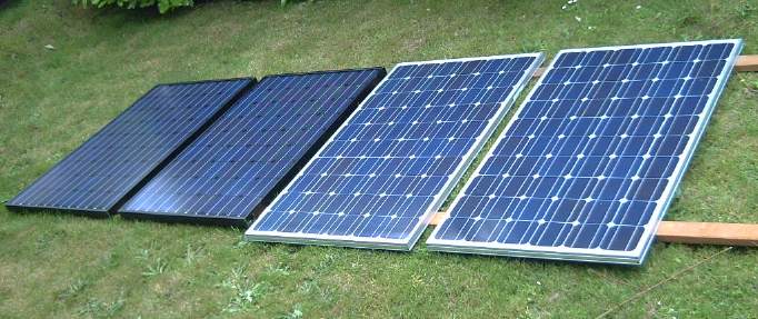
On the 29th I opened a Turquoise Energy account at Home
Energy Systems and bought four panels. They offered me
discounts on some marred or damaged panels, so I took four Sharpe
panels that weren't quite matched:
1. 240W (with gash on back plastic)
2. 235W (slightly bent aluminum frame - these two look
identical)
3. & 4. 208W * 2, still in box together (6" shorter. One had a ding
in the frame.)
Looks like these should have just enough room in line on the roof.
On the 30th, I bought a 1000 watt inverter (75$, a reduced
price) at Princess auto. I hooked it up to a NiMH 'car' battery and
plugged in my refrigerator. I went upstairs to get meters to monitor
performance. While I was up there, I guess the fridge happened to come
on by itself. Something that sounded like an alarm went off. By the
time I got back, thick smoke was coming out of the inverter. It should
have been plenty large enough to handle the fridge, and the manual
claimed it had overload protection. It shouldn't have blown. But the input
section had
fried and there were burned out transistors and circuit board. If this
was any indication, inverters weren't really a viable way to run
anything with a motor. (I took it back and got my money back.)
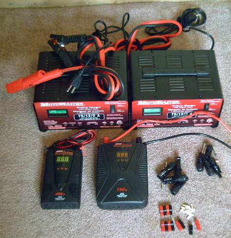 Equipment that can be purchased: two 12 amp, 12 volt
battery chargers for the 24 volts grid power to the system, a 400 and a
750 watt inverter, plugs to mate with the solar collectors, and APP 30
amp plugs. Evidently there is no standard for 12 or 24 volt plugs and
receptacles (except car cigarette lighter sockets), so I'm adopting
these.
Equipment that can be purchased: two 12 amp, 12 volt
battery chargers for the 24 volts grid power to the system, a 400 and a
750 watt inverter, plugs to mate with the solar collectors, and APP 30
amp plugs. Evidently there is no standard for 12 or 24 volt plugs and
receptacles (except car cigarette lighter sockets), so I'm adopting
these.
Missing: a piece of equipment to tie all these things together.
The next day, the 31st, a Canadian Tire store had a "Grand
Reopening"
sale. I decided to give inverters another try. I bought two 12 amp
battery chargers (@40$), two 400 watt inverters (@25$), and a 750 watt
inverter (50$), along with a long overdue shop vacuum cleaner (30$)
and a couple of much needed 33 drawer small parts drawers (@15$).
I tried the 750 watt inverter on the fridge. It was rated
for 1500 watts surge, but it shut off almost instantly when the fridge
came on: "E03" = overload. This was a big improvement over going up in
smoke, but it still didn't get the fridge going on batteries.
Additionally, the unit has a loud fan blowing a lot of air in a small
space. I couldn't have lived with that in the same room I was in.
Stalling the fridge gave a reading of about 19 amps. Sure
enough, it was over 1500 watts - theoretically it should blow the 15
amp house breaker every time it started, but of course it doesn't draw
that much for long enough to have an effect except on a fast responding
unit like an inverter.
12 and 24 volt fridges cost far more than 120 volt
fridges. Maybe if I get a cheap enough Wall-mart fridge, it would have
a smaller motor and would work with the 750 watt inverter. On their web
site it looked like they start at about 200$ - substantially less than
the 1500 or 2000 watt inverter evidently needed to run the fridge I
have, and a tenth the price of a 12 or 24 volt fridge.
The two 12 amp battery chargers would be the 120V grid tie
for the +12 and -12 volt supplies. 288 watts is only 1/3 of what the
solar panels put out, but the price was good and they should be
sufficient for now. (Best of all, they don't have fans.)
On June 2nd I saw some 70W inverters at XS Cargo for 10$,
made to plug into car cigarette lighters. I don't know what possessed
me not to buy a couple.
I had realized after buying the panels that I'd need
some of the mating plugs/sockets. Then I heard that I should get
aluminum mounting rails for
the collectors rather than attaching them straight to the roof. This
would cost all the money saved by finding discount panels.
The "minimal investment" project costs were starting to
mount. I decided to
make my own mounting system with wood, and I got the raw plugs to put
my own wires on. Without the pricey crimping tool, I could still solder
them.
Turquoise Battery Project
I didn't do a great amount of work on this, but
everything's been good progress and next month may bring Mn-Mn cells
that can actually light light bulbs and things.
Positrode Current Collectors
The positrode construction was still up in the air. There
were many possible ways to do them, none of which had proven very
practical so far.
So I started some experiments for
grafpoxy positrodes while I was doing epoxy in making the next motor.
First I made another sheet of it using fresh epoxy. It
got too hot in the oven. The PE melted and the epoxy bubbled up. But
the resistances were substantially lower, and didn't change much with
probe separation beyond a small distance. At the same time, I noticed
the first sheet was at least slightly flexible - it didn't seem it
would snap suddenly with a bit too much pressure. This was starting to
look
more promising.
Then I tried simply painting epoxy onto some polyethylene.
It spread much better than with the graphite mixed in. I sprinkled
graphite onto that and 'dusted' it around with a brush. I then mixed
the rest of the epoxy with graphite, and spread this grafpoxy onto the
top face of two pieces of the .03" PVC I've been perforating. Onto one
of
these I 'dusted' on more graphite. These all went into the oven at the
same time.
The first piece read very high to open. The first piece on
the sheet PVC was in the 100s of kilohms. The second was in the 10s of
KΩ, lowest where there were crusty clumps of graphite at the surface.
I took the two PVC pieces and put on another layer of
grafpoxy, then threw them (separately) into a jar with a little
graphite and shook it up. Then I glued a small square of sheet copper
with a hole in the middle onto each and put them back in the oven, as
terminal points to be above the cell. That
finished the gigantic 12g batch of epoxy I'd mixed. They were down to
3-5 KΩs range. Putting one probe on the copper only dropped it a KΩ or
so. It still seemed a lot higher resistance than the expanded graphite
at under an ohm. But I still don't trust that stuff not to degrade.
Each layer seemed to drop the resistance, but evidently it was going to
need quite a few layers. It would be better if it could simply be a
coating on a good conductor, but mostly the electrolyte seemed to get
at copper wires coated with grafpoxy and turn them to oxide. That
seemed unreliable, as least as I've done it so far.
I went to the graphitestore.com site, where I was reminded
of the carbon (graphite) fiber in the cupboard. Perhaps that
could be the low(er) resistance base for the grafpoxy coating. If I
painted it with grafpoxy, dusted it with graphite powder (and later
dipped the final product in toluene), it might give low resistance - at
least, low enough - stiff composite sheets which weren't too brittle,
could be cut as desired, and probably wouldn't degrade much, at least
not for years.
So the next day, the 8th, I cut two 80 x 80mm squares of
that awful fine dusty stuff, saturated them with grafpoxy, and then
brushed on some graphite powder. I also found the carbon "string" I'd
bought, and made 'terminal posts' by epoxying lengths of it and
sticking them together on the sheet.
The sheets mostly read in the hundreds of ohms, but here
and there were contacts under 100 ohms. The carbon string 'posts' were
the lowest resistance of anything I've made so far: under 200 to the
upper tens of ohms. Only dry cell
carbon rods and the expanded graphite sheets that seem to degrade are
lower (though substantially so).
With the last of the grafpoxy I made a third sheet with two posts, and
also four flattened strings/posts with no sheets attached, which could
replace the expanded graphite bars, carbon rods, or even grafpoxied
wires.With the strands spread out some, they had much more surface area
than a carbon rod or grafpoxied wire of similar size, and a flatter
profile for, eg, an 18mm wide flat plate electrode pocket shape.
I've just about decided the flattened string is the way to
go. Flattened strings down into the tall, narrow electrode pockets, a
cross string above the pockets to connect the vertical
bars/posts/strings together as a plate
assembly, and only one string sticking up through one hole in the lid
per plate. Perhaps I could goop in a piece of copper wire into the top
string, above the level of the lid, for the connection to the plate.
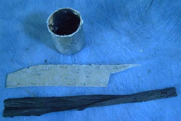
bottom: Grafpoxied 'flattened string' carbon fiber collector plate for
[virtually any] positrodes.
Zinc top & center elements are discussed in "Mn negatrode"
section below.
Near the end of the month, I put a flattened carbon
fiber/grafpoxy string into one pocket of the double perforated plastic
pocket I'd made, and stuffed in a bit of a mix of 25g KMnO4, 17.5g
graphite, .9g Ne2O3, and .9g of Sunlight dishsoap (for the sulfonates
to chelate the KMnO4). I added a little water to disperse the dishsoap.
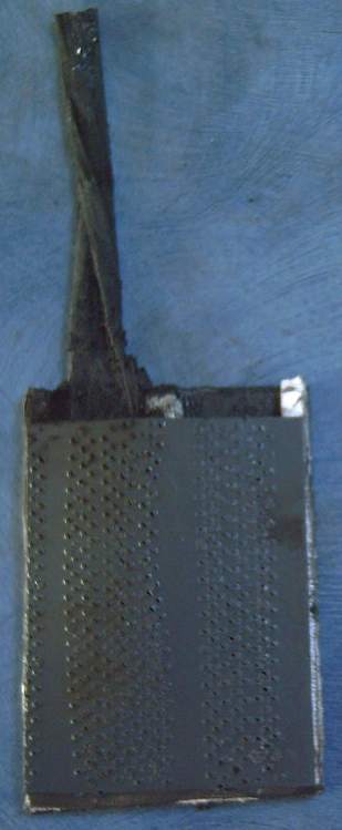 In the stuffing, the center part of the frame popped open,
in more than one place. The outer edge held. I think I want to try
another plan next time. Two possible plans are (1) to heat the
perforated PVC and form a narrow tube similar to the square ones, or
(2) use a 3-D printer to make rectangular ABS tubes, including very
tiny perforations all over. This last plan has a lot of appeal, as
however long they take to "print", uniform tubes exactly as desired
could be automatically produced, with no 'sewing' or burning to make
the perforations. Also, ABS wicks up water (as I've been discovering
with the ABS cases), and tiny holes wouldn't exclude water by surface
tension. On the night of the 31st I e-mailed to VICAMP, who have such a
printer, to see what a half dozen such
'baskets' might cost.
In the stuffing, the center part of the frame popped open,
in more than one place. The outer edge held. I think I want to try
another plan next time. Two possible plans are (1) to heat the
perforated PVC and form a narrow tube similar to the square ones, or
(2) use a 3-D printer to make rectangular ABS tubes, including very
tiny perforations all over. This last plan has a lot of appeal, as
however long they take to "print", uniform tubes exactly as desired
could be automatically produced, with no 'sewing' or burning to make
the perforations. Also, ABS wicks up water (as I've been discovering
with the ABS cases), and tiny holes wouldn't exclude water by surface
tension. On the night of the 31st I e-mailed to VICAMP, who have such a
printer, to see what a half dozen such
'baskets' might cost.
Sintered Zinc Manganese Negatrodes
On the 17th I finally got some 3/4" square steel bar to
fill 1/2 of the 1.5" x 3" electrode compactor. By filling only .75" x
3", 1/2 the area, twice the pressure can be applied with the same press.
I figured it should really have a grille for good
conductivity. A couple of aluminum posts I zincated worked, but the one
aluminum grille I did dissolved in KOH. I figured I had to get a better
coating -
zinc electroplate it after doing the zincate "primer".
Hey kids! Simple Zinc Electroplating
Interrupting the main flow of the topic, I got a zinc
electroplating formula with instructions ("How to Zinc Plate a Penny")
off the web. It proved to work well and is pretty safe, so I plan to
stick with it:
* 1 cup vinegar
* toss in some [cleaned - nylon scouring pad?] zinc pieces from an old
dry cell and leave it a few hours to let some zinc dissolve ("An adult"
should take the battery apart!)
* 5 teaspoons Epsom salt (MgSO4)
* 6 teaspoons sugar
I don't know what the sugar is for, but the solution works
well. No strong acids or ominous
cyanide compounds. The instructions said to use a dry cell for power. I
used a 6 volt power adapter with a 27Ω resistor to limit current. The
voltage into the tank was under a volt when it was working. (The zinc
source piece is "+", the object being plated is "-".)
The best part was "How to clean the penny": toothbrush and
toothpaste, then rinse. Plastic gloves were only to avoid getting
finger grease on the clean penny, instead of to prevent your hands from
dissolving. It seems to work just as well for cleaning wire and wire
mesh -
unlike a number of ways to clean parts that I've tried. Again, no
'baths' of hydroxide and nasty acid to take careful precautions with.
I like this system. I have no plans to explore any other
for DIY plating.
Of course the dry cell provides both the zinc for plating,
and pre-mixed, battery quality main ingredients for MnO4/graphite
positrodes. Only the carbon rod and a few case bits go to waste.
Zn-Mn Negatrode Assembly and tests
I mixed a batch of 40% Zn and 60% MnO2, with of course a
bit of Sb2S3. I compacted about 15g of this over a zinced aluminum mesh
and a zinced aluminum wire, size .75" x 3". I heated this to 230ºc
in the oven. It crumbled. I tried the kiln and raised it to 415ºc.
Zinc melts at 419. It crumbled. I did it over and heated it to
480ºc. The steel compactor parts turned blue. It sort of had a
skin this time, but the wire still fell off and chunks of it broke away
from the mesh.
I added some more zinc to the remainder of the batch to
make it about 50-50 wt% and tried again. The kiln hit 494ºc in 18
minutes. This one held together long enough to wrap some PP cloth
around it and sew the bottom so it would stay in place as in a little
bag. I put this into the Changhong cell with a couple of nickel
electrodes.
Maybe next time I'll try adding some Veegum (bentonite
clay) and or
Sunlight dishsoap (sulfonates).
It read 1.7 volts, and quickly commenced strong bubbling,
which I soon heard coming from inside the cell. The voltage was from
the zinc. Then I realized I'd essentially made a shorted battery: MnO2
and Zn are the positive and negative chemicals of standard and alkaline
dry cells, and I had put them together into one electrode. They were
both discharging.
Naturally, it was my plan to simply charge the MnO2 to Mn,
at which point the Zn would remain permanently in metallic form. I
hadn't considered the initial reaction between the two oppositely
charged substances.
I left it in and started charging at 90 mA, which pulled
the voltage up towards 1.8. I would have preferred a cautious slow
initial charge, but rapid reactions were happening anyway. I wanted the
zinc to stay metallic, and the MnO2 to become Mn2O3, Mn3O4, Mn(OH)2 and
then metallic Mn. It had a long way to go. When I opened the lid, I had
the impression the whole electrode had seriously swelled up from the
bubbles.
It was late by then. I left it boiling away and went to
bed. The next morning it was up to 1.85 volts, and with a 1Ω load, it
put out about 1.6V (also 1.6A) for 30 seconds, or 1.35V, 2.65A with a
.51Ω load. That made it my most conductive electrode ever. Previous
bests have been a little over an amp. Furthermore, some if not much of
the voltage drop was doubtless from the Changhong nickel electrodes. If
it stayed together and held
its charge, it would be a winner.
At virtually an amp-hour per gram as well as -1.56
volts potential, Mn makes a very energetic electrode. Notwithstanding
that it's half zinc,
since it has between 8 and 9 grams of MnO2 and hence over 5 grams of Mn
and 5 theoretical amp-hours, it should by itself match the 5 AH of the
2 nickel electrodes in the Changhong cell, which together are 6 times
its size. However, it'll take 3 of them sandwiched between the two
nickel electrodes to match the surface area. So I should make them
thinner (than 3mm), which will again up the current capacity to well
over (1.6*3=) 5 amps. With all four nickel positrodes and six of these
sintered zinc Mn negatrodes, the cells will be back to 10 amp hours,
limited by the nickel side.
The current drive, which would evidently be over 10 amps, would be much
better than the original NiFe cell. There's room for 9 Mn's in the cell
(Ni-3Mn-Ni-3Mn-Ni-3Mn-Ni), which would probably bring them up to at
least 15 amps if not 20, though adding no more capacity since there's
only 10 AH of nickel.
The current worked out to 55mA/sq.cm, which is typical of
good alkaline cells, and my best yet. Considering the double wrap of PP
cloth, the loose fit, and the triple-thick electrode, that seems quite
good. And it wasn't really charged yet.
It seemed to be holding its charge at least pretty well
when disconnected for a half hour. However, not all was well. The
aluminum leed wire had - probably acquired by oxidation of the zinc -
a gap in the plating, and corroded away by evening. Most of the
potential performance of the electrode didn't get tested.
From the initial reactions point of view, Zn and Mn metal
powders would be optimum, but I've already found that the Mn powder
isn't anything like as good as an oxide. The oxides are usually
nanocrystalline powders, whereas the Mn metal powder is just 300 mesh,
so it has much less reacting surface area per weight. Amp-hours would
be low. That's about the finest grit size available and making it seems
problematic.
But perhaps I could form Mn(OH)2 from the dioxide? That
should at least not be "overdischarged" to discharge the zinc from
metal to oxide. On the web the best way I could find to make Mn(OH)2
was to put a manganese salt into alkaline solution, which would turn
the salt to hydroxide. But the Mn(OH)2 would spontaneously transform
into Mn3O4 on contact with oxygen in the air (doubtless why I didn't
find any for sale), and at first it also seemed problematic to get
Mn(OH)2 except once it was submersed in the cell.
But if the electrode was made with a Mn salt, it would be
inert until it would become hydroxide when it was placed into KOH
electrolyte. (The electrolyte with all the K2CO3 would then have to be
changed - maybe after an initial charge or two.) The pottery supply had
MnCO3. This seemed to be worth a try. However, at some temperature,
MnCO3 would probably decompose to MnO + CO2. For the carbonate to work,
this temperature would have to be above the sintering temperature. On a
talk on "ScienceMadness.org" I found that it decomposes at 300ºC,
well below my ~490º sintering temperature. Also much below the
temperature to turn MnO2 into Mn2O3.
"MnO is difficult to prepare and
oxidizes readily in air to Mn2O3. It is
best made by heating the (insoluble) Mn(II) oxalate in a closed tube to
exclude air:
MnC2O4 + heat (c. 350C) --> MnO + CO2 + CO (but let the gases
escape).. I have made it this way and it is greenish.
Also you can make it by heating the carbonate, also excluding air:
MnCO3 + heat (c. 300C) --> MnO + CO2.
The MnO I produced this way seemed to be grey and possibly less pure
than the oxalate method."
I would seem then that the sintering the carbonate it
would reduce to the desired valence 2, but it could be difficult to
maintain it in that form. On later consideration of the options, I
decided this would be the best thing to try, and on the 22nd I bought
some manganese carbonate.
Next best thing would be Mn3O4. On heating to 600ºC
MnO2 converts to Mn2O3, and at 950º, to Mn3O4. It would be simple
to take a bag of MnO2, put it into a ceramic bowl, and heat it to about
1000º in the kiln to get Mn3O4 (weigh it to confirm reaction),
which would at least react with the zinc far less than MnO2 does.
1000º is however much too hot for sintering the finished electrode
- not only the zinc but the aluminum would melt, and the antimony
sulfide would probably undergo some adverse reaction.
Continuing to read posts in the same long discussion,
someone mentioned something else: a way to get Mn metal, the charged
form of the electrode, from the chloride. That might yield much finer
particles of Mn metal than the commercial product - maybe about as fine
as the zinc dust.
That would be the ideal form, and pyrotechnics places have
magnesium powder. But how does one extract Mn particles from a solution
without it spontaneously becoming Mn(OH)2, which it does in water
without the stibnite, and then Mn3O4 on exposure to air? It turned out
to be far more complex than it seemed - it can't be done in water. (The
text of the reactions vanished somewhere during editing - no matter
since it's impractical anyway.)
Another method, the one by which pure Mn was first
obtained,
would be to heat
MnO2 + C => Mn + CO2. But this evidently makes a blob of
Mn metal, not a fine powder.
Noted: If MnO and Mn(OH)2 become Mn3O4 on exposure
to air,
I can see it's important to flood the electrode completely and to have
a pretty well sealed cell to prevent self discharge. For a sealed dry
cell, perhaps you'd want to fill the cell with inert gas rather than
just air. For higher voltage and energy cells, things get more critical
than for "low tech" like nickel-iron.
I reflect on how much easier making electrodes would be
with Changhong's perforated metal pockets to put the MnO2 into. But
then, this new sintered zinc type appears to be a better, higher
current electrode, so it's worth exploring.
Also, initial oxidation of the zinc plating might well be
causing the corrosion problems which I didn't foresee, and that would
also happen with zinc plated pockets. Certainly I thought there must be
something wrong with the nails or bolts I used in February, but perhaps
it was the reactions taking off the zinc plating. The second
zinced electrode posts I put in seemed to work. Maybe it was just
because they were second, after the initial MnO2 reduction reactions
were done, rather than there being any original problem with the first
ones. Mn(OH)2 or at least Mn3O4 should be better starting forms. Maybe
it's a good thing I didn't talk Changhong into making a few to try out
- they just might have corroded away like this one.
High Current Comparison: Ni-Fe & Ni-Mn
Well, this is obviously preliminary without a properly
working Mn electrode. But I tested the high discharge currents of four
flooded Ni-Fe 10 amp-hour cells for comparison with this and future
efforts. After 10 seconds (tho the voltages were still dropping by the
second) I got the following average readings:
Initial open circuit voltage: 1.32
Load - Current - Voltage
2.2 Ω - .55 A - 1.20 V
1.0 Ω - 1.08 A - 1.08 V
.51 Ω - 1.82 A - .93 V
.22 Ω - 3.27 A - .72 V
Open circuit voltage a minute or so after the tests: 1.23 (this would
have recovered some more over the next few minutes) These cells might
be considered to have been in the mid-upper state of charge.
The readings taken well before the Mn electrode failed seem very
favorable when it's considered that it was by no means fully charged,
they were taken after 30 seconds of discharge rather than 10 (and that
the voltages appeared pretty stable rather than dropping), that the Mn
electrode was only about 1/10th the size of the iron ones, and 1/2 the
nickel electrodes were removed from the cell:
Initial Ni-Mn open circuit voltage: 1.83 V (seemingly closer to zinc's
potential than to manganese's)
1.0 Ω - 1.6 A - 1.6V
.51 Ω - 2.65 A - 1.35V
It's clear that it's the iron side that limits the current
of the Ni-Fe cells. If 6 of these small Mn electrodes were used with
the four Ni ones to match one face of their surface area, one could
multiply these currents by about 6. (9 would fit in the cell. This
would up the current still more but probably not the amp-hours, which
are limited by the nickel hydroxide electrodes by the time 3 or 4 Mn
ones are used. One caution is that much of the current and voltage
might have been being supplied by the zinc, the manganese not being
very much charged yet. But one anticipates it could only get better,
not worse, with fully charged manganese.
For the first time in the Turquoise Battery project, these
currents are in the ranges wanted for electric transport batteries.
Assuming I get the problems ironed out and everything tests out well,
Changhong could mass produce 2 volt Ni-Mn cells with at least ten times
the current capacity of their 1.2 volt Ni-Fe's.
For the 'moderately alkaline' KMnO4-Mn batteries of even
higher energy density, positrode conductivities now need to be improved
to match these excellent negatrodes. The grafpoxy/carbon fiber work
near the start of the month looks promising, but remains to be put to
the test.
Another Mn Negatrode Idea
top: Bottom half of the zinc C cell casing.
mid: 100% Zinc collector plate for Mn negatrodes, from the C cell.
(bottom: previously discussed grafpoxied carbon fiber positrode
collector plate.)
On the 24-25th I had a new idea. The plastic pocket cells
with a wire or rod in the middle of a fat square electrode weren't very
conductive. The sintered cells were pretty fragile. Both needed the
MnO2 discharged to MnO or Mn(OH)2 to prevent initial oxidation of zinc
coatings. (Something I still haven't found is pure zinc wires, which
would mitigate the problem.)
The pocket cells could be made more conductive if they
were thinner, if they had a flat sheet of zinc running across the
middle instead of just a rod, and perhaps with zinc powder in the
chemical mix to enhance conductivity. With a flat piece of solid zinc,
even
the harsh initial oxidation would (I trust) only affect the surface
layer and
solid zinc would remain within. Since it's still all zinc, MnO2 could
be used without ruining the electrode during the initial charge. Then
the zinc's surface would charge back to metal. Flat zinc could readily
be had off dry cells, and also one can probably buy zinc sheet metal if
needed. (Better, Mn2O3 or Mn3O4
could be used if one has a kiln to heat the MnO2 - or a torch might
work too, and would limit the oxygen - perhaps even MnO could be made.)
It also occurs to me that manganese carbonate (like zinc
carbonate) is likely to convert to hydroxide if the electrode is
immersed in potassium
hydroxide (while contaminating the KOH with K2CO3). Thus, using MnCO3
may solve the problem of discharging the zinc, even without heating.
I've decided to try .25" x
.5" x 2.5" perforated plastic pockets with a .5" wide piece of zinc
through the middle (with a segment sticking up for a terminal leed),
leaving two fairly thin slots for the active chemical mix, with (20% ?)
zinc powder for better conductivity. Putting a center post in
before ramming in the chemical mix was problematic, but with a wide
piece of zinc, one side could have a flat metal filler inserted while
the first side was being filled. This would then be removed and the
second side filled.
If it worked well, improvements could be made to the soft
zinc center piece later for more optimum contact with the chemicals and
hence higher currents - punch holes in it or even expand it into a
mesh for the part inside the electrode.
The grafpoxied carbon fiber "flattened string" strip in
the positrode should be a pretty good match with the zinc strip in the
negatrode. The same perforated ABS outer pockets might
be used for both.
As reported above, I put in my request for perforated ABS
baskets on the night of the 31st.
http://www.TurquoiseEnergy.com
Victoria BC