Turquoise
Energy Ltd. News #53
Victoria BC
Copyright 2012 Craig Carmichael - July 2nd, 2012
http://www.TurquoiseEnergy.com
= http://www.ElectricHubcap.com
= http://www.ElectricWeel.com
Hilights:
- The Mushroom Electric
Outboard Motor [Design]
- 3D plastic printing to revolutionize home battery making
Month In Brief (Summaries)
In Passing (Miscellaneous topics
and editorial comments)
- War on Greed - Mercy & forgiveness - How to stop the Peace River
Site C Dam
Electric Hubcap System
* Improved Outboard From Scratch Design: The "Mushroom Outboard"!
* U-joint 90º Drive - socket wrench U-joints - tests show it works
fine.
* Sprint Car: Torque converter is ready; needs motor, controller,
batteries.
* New motor plate drill templates: from hand calculator to...
spreadsheet G-code.
Planetary Gear Torque Converter
Project
* Planetary gear torque converters are already in use! - Toyota Prius
& more.
* Sprint 'clutch' linkage installation.
Solar Electricity Project
* Modules of the "DC Grid Tie" unit.
* Solar Hot Water addition (doubles electricity savings) -
plastic/rubber mat collector, & Pump Control Module.
Turquoise
Battery Project
* RepRap: 3D printing of plastic parts will create battery making
revolution
* Conductive carbon fiberized ABS printing plastic for positive
electrodes ("posodes")
* 3D electrode pockets from Camosun College/VICAMP
* Next Mn negative electrode ("negode") with latest everything
* Mn negode doesn't work in KOH electrolyte (pH 14) -
discharges
spontaneously
* Mn negode does work in KCl electrolyte (at moderately
alkaline pH)
* Cells need seal to keep O2 out to prevent self discharge
No Project Reports on: Magnetic Motion Devices, Weel
motor, LED Lighting Project, DSSC
solar cells, Pulsejet steel
plate cutter
Newsletters
Index/Highlights: http://www.TurquoiseEnergy.com/news/index.html
Construction Manuals and information:
-
Electric Hubcap Motor - Turquoise Motor
Controller - 36 Volt Electric
Fan-Heater
- Nanocrystalline glass to enhance Solar
Cell performance - Ersatz 'powder coating' home process for
protecting/painting metal
Products Catalog:
- Electric Hubcap Motor Kit
- Sodium Sulfate - Lead-Acid battery longevity/renewal
- NiMH Handy Battery Sticks, Dry Cells
- LED Light Fixtures
Motor Building
Workshops
...all at: http://www.TurquoiseEnergy.com/
(orders: e-mail craig@saers.com)
June in Brief
I can hardly believe that I've taken on yet another
project, a 'novel' solar electricity system,
following so soon on
starting to explore magnetic systems, and with quite a number of
unfinished
or not quite finished projects still on the go... and when I seem to be
waking up every morning with a boundless supply of lethargy, then
tiring out by mid afternoon. (Perhaps a holiday would help? ...Hmm, B
vitamins seem to help) Yet
all these fields
seem so ripe for the harvest, and the workers are so few, that the
temptations are irresistible.
With western quasi-democratic civilization apparently
being ripped to pieces by ever more heinous financial and political
crimes, I spent considerable time trying to make sense of it all and
encapsulate my view of the big picture in an editorial (below), "War on
Greed".
I hoped I could get the solar collectors mounted in a
week, and
then pick away piecemeal at the electronic and electrical aspects of
the project while I got back to finish or
at least to progress on other things. But safely mounting them on a
south
facing roof with a
45º slope 26+ feet above ground would be no trivial undertaking,
and
the
prep, pursued at first part time and then only occasionally, drew out
for an extended period. Finally on the last day of June I finished a
scaffold-ladder to hook over the peak and lie on the roof of the house.
Most
people with shorter houses and flatter roofs, or a ground area to place
solar panels, would have
a much easier time of it. My south roof is an excellent location and
angle, but putting the collectors at
the base of the house in the tree shadows was looking very attractive.
On July 1st I climbed a hill and overlooked many homes... none with
solar panels. It needs to be made easier and cheaper. The panels are
good enough: The things that go around them need work, and need to be
affordable.
The hot water tank "dump load" idea meant there'd be a hot
water preheater tank, which I decided could go in the upstairs bathroom
next to the regular water tank as part of remodeling that bathroom. In
for a penny in for a pound... I bought a dual 2' x 10' (4 square
meters) plastic mat "swimming pool" hot water solar collector and DHW
circpump for a bill of around 500$. The hot water tube panels should
heat the
tank at least as well as all
four electric panels if not better, doubling the electricity saved for
1/4 of the price. Other motives for
this addition were to cover up the shingles coming apart at the far
edge of the south roof (the first PV panel does the other edge) and
stave off reshingleing a few years (10?), and to
create and test an optional "module" for the DC Grid Tie box: a
differential
temperature pump switch module.
Of course, getting the panels up will just lead to more
work to
get everything running.
 Meanwhile
there was the unfinished new motor for the stripped Honda Electric
outboard. But it didn't look like a new Electric Hubcap motor
would fit readily under the Honda hood. I could make a new hood... ugh!
Then I thought up a
"U-joint" design to mount the motor at a 30º angle... and then I
thought:
maybe U-joints could be used to transit
the shaft rotation from vertical to
horizontal down at the prop, eliminating gears or pulleys with belts or
chains. A test with socket wrench U-joints showed it was likely to work
smoothly without much friction. (Contrary, as is often the case, to all
advice on the matter.)
Meanwhile
there was the unfinished new motor for the stripped Honda Electric
outboard. But it didn't look like a new Electric Hubcap motor
would fit readily under the Honda hood. I could make a new hood... ugh!
Then I thought up a
"U-joint" design to mount the motor at a 30º angle... and then I
thought:
maybe U-joints could be used to transit
the shaft rotation from vertical to
horizontal down at the prop, eliminating gears or pulleys with belts or
chains. A test with socket wrench U-joints showed it was likely to work
smoothly without much friction. (Contrary, as is often the case, to all
advice on the matter.)
With this exciting
design idea, I
decided it
would be better to do the "outboard from scratch" which could then be
replicated, and forget putting
time and energy into the "one off" Honda. Unfortunately, this meant
calling the
fisherman to say things couldn't be ready this season, so I was
delaying or perhaps defaulting out of a promising sounding
contract
- rats! Making a mock-up of the design suggested a name - the Mushroom
Outboard. I concentrated on getting the U-joint 90º drive
working nicely and figuring out how to mount its pieces.
In a period starting around the middle of the month, I did
much shopping at odd locations, mostly for the projects. I made several
visits to Camosun
college's VICAMP facility where they 3D printed me some 'perforated'
ABS plastic electrode pockets, and in
general somehow I seemed to spend my days driving around rather than
getting any
work done. The second batch of pockets on the 15th looked quite usable,
so with zinc and grafpoxied carbon fiber current collector plates, I
was ready to try making a decent test cell. Camosun's bill however came
to
325$ and I was glad I had ordered my own 3D plastic printer (and some
ABS printing filaments in several colors). By the
time it arrives and I get it assembled, I'll be wanting to make
electrode pockets, cases
and pressure seal/relief caps.
Having the electrode pockets, I turned some MnCO3 into MnO
to make a 'negode' with a solid sheet zinc (from a dry cell) current
collector. Theoretically
the MnCO3 could be 'calcined' to MnO at the low temperature of
200ºC, but
it didn't work "as advertised" on Wikipedia... nor at 230 or
260º... and in the end I sprinkled the powder through a propane
torch flame 3 times. Hmmf... I could as easily have reduced MnO2 to MnO
by the very same technique!
I put the completed Mn electrode into the Changhong cell
together with two NiOOH electrodes, making a Ni-Mn cell. The
conductivity was much lower than for the sintered electrode... it
seemed to work, but finally I realized the voltage (1.8V) was too
low... the active chemical was actually the zinc current collector and
current raising zinc powder rather than the manganese. The manganese
wasn't charging, and if enough current was applied to force it to
charge, it soon discharged back down to 1.8V, where it stabilized.
So I put together a whole Mn-Mn cell and used KCl
electrolyte. This soon charged up to 2.25 volts, which very gradually
dropped to around 2.15 V idle, notwithstanding liquid leaking out the
top corners. Longer charging (days) brought it up to around 2.4 volts.
Zinc would have been around 1.85 - 2.0 volts, so the manganese had to
be charging. Gradual self discharge over many hours is probably
explained by air leaking into the cell - oxygen discharges alkaline
negative electrodes.
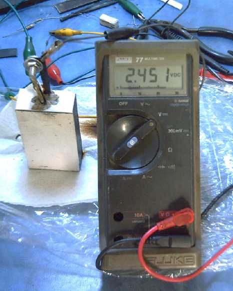
Yes the meter is accurate - it's a whole volt higher than most alkaline
cells.
No the cell isn't on charge. (It was a few minutes previously.)
Yes it's one single MnMn 'moderately alkaline' battery cell.
It seems best now to put the batteries on hold until the
3D printer arrives. Then things should become much easier to make.
Indeed the whole idea of 3D printing homemade battery parts (using any
alkaline type of chemistry) looks so much simpler as to probably amount
to a battery making revolution.
I also got the 'clutch' cable and slip control rope
assembly installed in the Sprint car. I hadn't been sure how I was
going to do this until I finally thought of using a small rope and
pulleys to go between spacially unrelated points 'A' (slip tension
rope) and 'B' (shift cable).
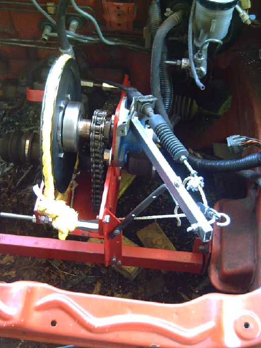
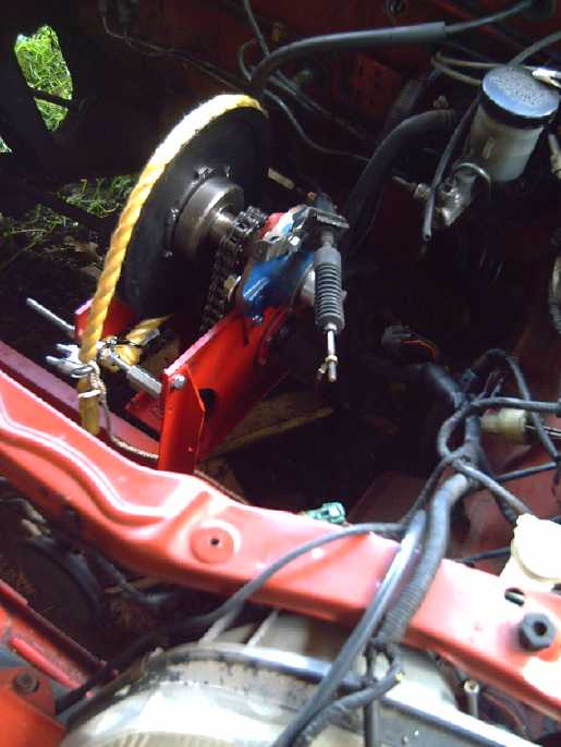
Control Clutch (ex gearshift) cable linkage to Slip Control V-Belt
pulley
via small rope & 2 small pulleys
(Yes, it could be tidied up. I wanna see it work first.)
With the car being now ready to test except for a motor,
controller and batteries, I finally got the stator plate drill template
worked out and drilled the holes in the waiting motor parts just before
month's end. I fooled around with CAD programs and "DXF to G-Code"
converters without much luck. Then I simply entered the text of the
main body of the G-code into spreadsheet cells appropriately
interspersed with the co-ordinate calculations, then just cut and
pasted it into the program file, eliminating most of the grunt work. At
last, a way to simplify it!
I need to put together at least a couple of motors and
controllers at this point. For a guy that wants to sell motor kits and
controllers, I sure don't seem to be producing them very fast!
In Passing
Incidental news, editorials
- Wanted: War on Greed, Corruption
&
Violence - Mercy is the way to peace & progress - Are Universities
Superfluous?
Without a serious enemy in the world, USA's
"leaders" are fond of declaring futile, never ending
wars. At home: "War on Drugs";
"War on Poverty"; "War on Terrorism". Abroad: bribes, threats,
assassinations and other "power plays", and trumped-up excuses for
invading, occupying and plundering weak
countries. For personal gain and power, they
have been
fabricating trouble and creating artificial problems to fight an
increasingly
effective undeclared war on the long cherished rights and freedoms of
their own
citizens.
This cancer has
been festering for a long time, and is now malignant, rapidly spreading
- the perpetraitors are now in almost complete control. They are intent
on turning America into everybody's
enemy, the global bully, enslaving their own citizens at home and
stirring up trouble all around the
world. Psychopathic "major scandal" level offenses by those in economic
and political control have
overwhelmed the defenses of law and order. Canada and
seemingly Britain and Europe are now trotting along beside the USA in
her path to ruin like Italy did
Germany in world war two, eager to outdo her in malicious malfeasance.
But it
would seem
they are all trotting along as the puppets of the
multinational banks
and other entrenched corporate evil empires - the ruling "cleptocracy"
as it's coming to be known.
The earnest attempts of citizens with ideas and ideals to bring about
justice, order and progress are ignored, even branded 'terrorism' and
maliciously suppressed, while far too many thoughtlessly while away the
hours watching entertainment TV, ignorant of the turbulent currents
swirling around them. Western
civilization as we know it has
apparently reached an evolutionary dead end.
With the new
interconnectedness of the internet,
people around the world are just starting to wake up to the fact that
everyone
everywhere is caught in plights to related to their own, and that
except for small agitating and greedy minorities everywhere (mostly in
control), they are
mostly
goodhearted people who have no evil plans for jihad against anybody
else. But no one is safe until everyone is safe. The most powerful
nation can't protect its people against someone who has nothing more to
lose with a homemade bomb strapped to his belt. At some point,
everybody, everywhere, including those pulling the
strings - or their children - will start to sicken of this fools' game
and turn long nurtured energies of fear, hatred and greed to love, to
the
bearing of fruits instead of thorns. There are small signs that
attitudes
are everywhere starting to change.
But even those ultra rich who already want change just
don't
know where to start. The way things
are going, seemingly from bad to worse to worser, what could possibly
trigger favorable outcomes? Unpleasant scenarios of conditions inimical
to progress like widespread rioting and mob actions come readily to
mind. "Those who make peaceful evolution impossible make violent
revolution inevitable." - John F. Kennedy
But the pendulum may
be reaching its maximum swing
because the global currency system seems about ready to crack. Many
analysts have been warning for several years of bank frauds and scams
on the global scale. A rapidly growing number of people have now joined
them in saying financial collapse, whether imminent or staved off until
later, is
now inevitable... and that it's a necessary evil. With western media being beholden to the
corrupt, the only news network covering this, seemingly the biggest
story in the world, is rt.com.
Those in control of the
biggest
banks are now openly manipulating everyone to economically pillage the
world,
stealing every fund including peoples' retirement savings and even from
their bank accounts,
and driving whole nations to economic servitude and ruin. (Canadian
bankers are evidently not innocent, BTW.) Having
acquired nearly all the fiat money for themselves and realizing that
this very fact is making it worthless while also dropping property
values, they're now trying to steal the last things likely to hold
their value - gold and silver. (They seem to have set their sights on
Greece's and Italy's gold now.) And they pay off the leading
politicians
- or in fact are doing what
the politicians want - so (except in Iceland) they aren't being
arrested or reined in. No banker will today invest in a productive
enterprise: stealing money is easier and more profitable.
If the banks close (AKA 'an extended bank holiday'), and
if fiat currency
collapses, along with many destabilizing and perhaps devastating
effects, all the entrenched vested interests will probably lose their
economic stranglehold. An unsettled and turbulent but potentially
fertile period
will likely ensue, when all sorts
of beneficial changes unimaginable under today's repressive conditions
can take place.
Then people can start working together, to
tackle the roots of the real problems: to
find and adopt sustainable social, political and economic systems that
citizens actually have effective control over.
If there are wars to be declared, they'll be "War on Greed", "War on
Corruption", and "War on Warmongering" - which "wars" will really
just be the long overdue corrective operation of the presently
dysfunctional wheels of government. If institutional and societal
changes create conditions
unfavorable to empowering rogue elements and draw most
everyone over to the same
side, working towards the same goals of a new, sustainable
civilization,
then the world will begin to draw together and become peaceful,
prosperous, and sustainable. The brotherhood of mankind will be
dawning.
The contribution of each individual defines the whole. For
the immediate future, in order to be in
a position to contribute rather than to be in personal or family need,
the advise
of those in the know is to have money in cash, put aside good
food and
other
necessities, and buy some silver and or gold. (eg: there are coin and
bullion dealers in every city, who sell 1 oz pure
silver coins, at about whatever silver is currently valued at plus some
mark up.) I don't
think anyone should do anything rash or irreversible, or panic, but the
more people who
are prepared to weather an initial shock of closed banks and disabled
or empty ATMs, with the likelihood of empty grocery stores, the better
for everyone. Ongoing major withdrawals - gradual
bank runs - are already on in Europe. At the moment, if confidence in
fiat currency
fails and suddenly the banks close, it appears likely to catch 99% of
the population by surprise.
I've heard it said that simply thinking about it and
withdrawing money to prepare will cause it to happen. If the world
banking system is that bankrupt, it can only affect the timing a bit,
and will seem poor logic later if you have nothing to eat.
I regret feeling the need to have written this piece, and
I'm aware that it may possibly be many months premature, or that things
now broken will get fixed and in a year or so I may look like an
overreactive fool. But having seen a glimpse of what appears to lie
ahead and may be triggered imminently, I need my conscience to be clear
if people are suffering for want of preparation, that I passed on the
warnings of many seemingly good judges of finance and economy as best I
could.
---
In the middle of the month, I heard rumors of grand plans to reorganize
the world's
money system when or if the banks shut down. When you bring
in your cash, you'll get to trade it in for the new money. But when you
bring in your six billion dollar bank account, questions will be
asked... like where did you get the money?, and, is it
a reasonable amount for you to possess? This is about the most hopeful
thing I've heard for some time.
If the rumor is true, it might help to explain why so
little seems
to be being done to combat the financial terrorism: many people
have decided that the sooner the whole system crashes, the sooner it
can be fixed. Such a plan, if it really exists, tho it could hardly be
implemented in a day or
a week, could do much to mitigate and shorten the unsettled
period, and to improve the likelihood of good outcomes.
But I fear it sounds like wishful thinking - too good to
be true.
---
Some Egyptians were demonstrating early in June, calling
for
vengeance
against Hosni Mubarak and his family and the people formerly involved
in running Egypt. Yet Mubarak simply 'inherited' dictatorial power when
Anwar Sadat was murdered. As far as I can tell from what little news
ever
reached the west, his long regime was pretty peaceful, even uneventful.
Egyptians who stayed home may be grateful to him for stepping down
peacefully instead
of fighting it out to the end - and maybe winning - with all the
bloodshed, turmoil and ruin that would have ensued.
Punishing Mubarak and those around him will only ensure
that others having power, all around the world, will never dare to step
down and will have to be removed, if at all, by ultimate force. The
protesters want more violence against him than he was willing to
unleash against them. It is the wrong signal to send. Mercy and
forgiveness - especially to those who surely have only tried their best
according to the lights given them - are the paths to peace, progress
and prosperity. "Blessed are the merciful, for they shall receive
mercy." "Blessed are the peacemakers, for they shall be called Sons of
God." - Jesus
Even the corrupt bankers and politicians who are bringing
down civilization are our erring brothers. If we "burn them at the
stake", they can make no repentance of value to the planet, but if we
are more merciful, perhaps many of them will reform, and being capable
people who know the problems from within, they will be glad to help
devise effective systems to counter the growth of such problems in the
future.
---
How to stop the Peace River Site C Dam
The best way to do something positive is to personally
reduce your own grid energy consumption. If your dwelling has no other
major waste of power, LED lighting will reduce the bill significantly.
With the present cost of LED lights, that may seem like more money than
it's worth, but if everyone in BC did it, we'd probably save
substantially more energy than Site C is to produce for far less money.
If the available bulbs aren't bright enough, a "Y" adapter lets you put
two "bulbs" in one socket, space permitting. And of course, I'll
happily sell my brighter LED light fixtures if anyone asks. (The
yellowish 800 lumen Phillips at Home Depot for 30$ are the brightest
LED "bulbs" I've seen locally. They were 20$ with a BC Hydro rebate for
a while.)
One person said he got an electric car and also put in LED
lighting, and his electricity bill went down - the LEDs
evidently save more than the car uses.
The next option is to produce energy yourself: install
solar panels or other green energy source, and or solar collectors for
hot water. Our often overcast west coast isn't the best place for PV,
but wide adoption would again reduce grid consumption more than Site C
will increase production.
And a small grid tie inverter for solar panels is
evidently now affordable, if not economic strictly in dollar payback
terms. (I must look into this - seems to me I was told you can get an
inverter that's on or off grid, so it can switched to power a separate
outlet(s) during a power failure.) With that and BC Hydro's new 'smart
meters', I think it should be pretty simple to put power out to the
grid to reduce your bill - or even get paid.
Perhaps I should look into that as an alternative to the
hot water tank "dump load" idea.
Of course, these things can only work if lots of people do
it, and
it seems a shame so little of that 8 billion dollars for Site C -
around
2000$ per every BC citizen - has been put into incentives to help
people accomplish this. But every bit helps, and if starting now
doesn't stop Site C, it might head off "Site D" or other megaproject.
Electric
Hubcap Motor System
Improved Outboard from Scratch Design (forget Honda conversion)
In considering how to fit the motor under the hood of the
Honda outboard, it occurred to me to mount it at an angle and put in a
U-joint... one from a 1/2" socket wrench set.
Then on the 3rd, it occurred to me that instead of having
a gear at the foot of the outboard, 2 or 3 or 4 U-joints in a string
could
make the 90º bend to the propeller shaft. This assembly, with no
gears or pulleys, could make for the narrowest outboard foot ever. In
fact, perhaps there need be no foot per se except a small bulge where
the prop
shaft comes out, for the seal. The leg would simply end just below the
prop with a skeg.
This started to make doing the "outboard from scratch" sound
easier than trying to fit the motor into the Honda... and it
should make a better outboard motor, eliminating the
unfavorable gear reduction at the foot of gas outboards, probably
with improved efficiency. Perhaps doing the Honda would be less
productive than forging ahead and making this new design, which, once
finished, can be produced. Since
I plan to do an outboard from scratch sometime anyway, eliminating the
Honda 'one-off' actually reduces the extent of the outboard projects
overall.
Once I started thinking about it, by the 4th design
details started coming clearer. A short piece of 12" culvert pipe would
(just) fit over the
Hubcap motor for a housing. Ventilation air would come in the front at
the top, and exit out the bottom near the front, which would be inboard
from the transom. (A splash guard around the outflow might still be a
good idea.) A broad
slot for intake air might also be the wiring entry, allowing the heavy
wires to twist inside for steering, rather than moving a long way side
to side where they entered at the front of the rim.
At the top of the
leg, a toilet flange I bought for an LED lamp base would glue into the
leg and make a good flat seat for the base of the motor compartment,
connecting it solidly to the leg.
If the drive shaft into the leg was made to drop into the
bottom end rather than affixed, the prop shaft assembly could be
lowered diagonally into the leg and then straightened as the shaft
poked out the hole, which could be a screw-on pipe fitting with the
shaft seal. Then the seal would be screwed on and the shaft would be
inserted from above.
The bottom of the leg would simply be glued shut (except
for a threaded in replaceable prop shaft seal/fitting), reducing the
chances of leaks. Oil for the lower unit could be poured in from the
top or a couple of screws could go through the wall in the traditional
manner.
The transom mounting bracket details were still fuzzy.
Potentially the round top end of the leg could simply twist inside
something of slightly large diameter. Or stainless steel clamps
around the pipe could hold a hinge pin at the front. Either way, the
mount would still
need to pivot up to lift the leg out of the water, presumably on a pin
at or above transom level. And there should be a 'straight ahead' latch
for rudder steering installations, and a catch for reverse to prevent
the leg rising up. Another thought was that the farther forward the
pivot was, the less the wiring would need to move for steering. I'll
probably opt for the front pin.
Perhaps the motor controller could optionally mount on the
front side of the transom mount. Optionally because that wouldn't be
the best for vessels using an outboard bracket - the controller should
be within the craft away from waves and spray.
Something that had been concerning me was that surely I'd
never get a long enough piece of PVC pipe in the oven to soften and
bend it. But when I measured against my boat, I found it only needed to
be
20" long. The oven would take 21-22" straight, and perhaps a bit longer
diagonally. Only the lower end gets bent to the streamlined 'teardrop'
profile, since the top is out of the water and also it has to mate with
the round ABS toilet flange. Furthermore, these tubes can be extended
with
another piece having a flange. If I only bolted the top to the leg
instead of gluing it, extension to make it a "long shaft" would require
only another (flanged) piece of PVC pipe and a longer driveshaft -
common 1/2" square steel rod.
The Hubcap motor for the top end is a given, so the first
step in all this, I think, is to create the 'foot' mechanism holding
the
prop shaft, bearings, U-joints, and the socket for the vertical
driveshaft. The size and shape of that unit will determine much of the
lower end geometry.
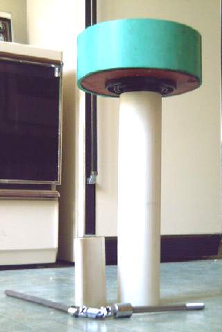
On the 6th I
put the outer pieces together in a 'mock-up'. Imagining a
domed cap to shed water, the wide, round top with the 4" 'stem' in the
center suggested a name: the Mushroom Outboard.
Also on that day, someone who didn't think highly of the U-joints idea
mentioned looking up "right angle drives". Later "homokinetic drives"
were mentioned. Amongst many ads and info
for beveled helical gears, worm drives, and couplings for misaligned
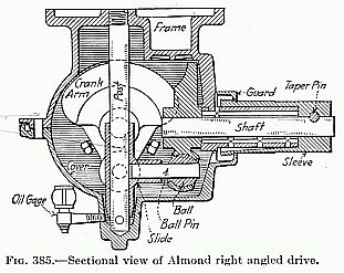
straight shafts, I found this, the "Almond" shaft coupling:
Taken from Wm. Griswold Smith's "Engineering Kinematics"1930.
The drive
shaft ends keyed to a ball joint with integral counterweight. [The ball
joint is similar to that of a rear sway bar end link]
A pin passes through the ball and into the 'trunk' of a "T" shaped
sleeve whose cross bar slides vertically on a fixed post.
The visible "T" actually has a 2nd "trunk" at a right angle to the 1st
[i.e., on the 'Z'axis ] which connects to the pin of the output shaft.
The motion of the pins is helical and reciprocal. The efficiency is
claimed to be 90-93%, [i.e., better than bevel gearing]
The description and diagram seemed clear as mud, so I did
a search on the
specific name, and came up with some you-tube videos showing the
'almond'
and a couple of other types of gearless right-angle shaft direction
changers.
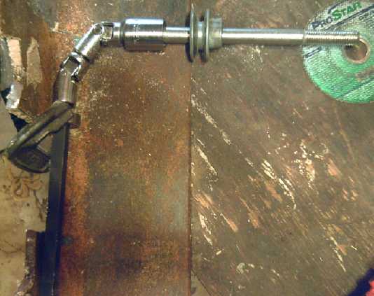 I still
thought the U-joint looked the most promising, but the discussion list
was skeptical. So I made a little test, with a bearing on the input
drive shaft (1/2" square, black), clamped down, and a 5/8" center
pulley "bearing" on the 5/8" propeller shaft (bolt).
I still
thought the U-joint looked the most promising, but the discussion list
was skeptical. So I made a little test, with a bearing on the input
drive shaft (1/2" square, black), clamped down, and a 5/8" center
pulley "bearing" on the 5/8" propeller shaft (bolt).
I simply held the pulley and the prop shaft with one hand
while I turned the drive shaft with the other. If I tried to angle it
more than 90º, eg 110º, the torque to turn it got noticably
"lumpy". But at 90º, it felt
pretty smooth, even when I put some resistance on the prop shaft.
So I think
two U-joints are both the best and the simplest idea. If the socket
set ones wear
out too rapidly,
I'll try to make something better along the same lines. (I can
visualize an 'ideal'. In essence similar, but the center would be a
single piece instead of two pieces pushed together, and the pins would
be beefed up and in line, perhaps with bronze bushings. But I'd rather
not try making it unless I have to.)
Saying it seemed to work well didn't convince everyone
either. A working outboard
might do it, but I'm not so sure - opinion was pretty averse.
On June 9th, I thought of a good way to put it together:
in a "sandwich" of aluminum plate bread. The bearings would sit upright
in rectangular grooves or holes in the the aluminum, like car tires in
potholes. When the two pieces were bolted together with a couple of
rectangular pieces between to hold them straight, the bearings would be
held rigidly in place.
This proved more difficult than expected because I
switched from ball bearings to sintered bronze bushings, and some of
the parts had a greater diameter than the bushings.
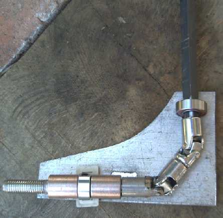 Then I
realized I could eliminate one of the moving
parts and make it more solid by making the prop shaft into the final
U-joint segment. (And there was no point continuing with the housing
without having a final shaft configuration.) This needed a stainless
steel pipe of the right inside dimension to slip over the bolt (whose
hex head was ground down to an indented rectangle), cut to end in two
"arms" as the end piece of the U-join. (In fact... all the pieces could
be replaced by 1/2" square rod and other off the shelf stuff.)
Then I
realized I could eliminate one of the moving
parts and make it more solid by making the prop shaft into the final
U-joint segment. (And there was no point continuing with the housing
without having a final shaft configuration.) This needed a stainless
steel pipe of the right inside dimension to slip over the bolt (whose
hex head was ground down to an indented rectangle), cut to end in two
"arms" as the end piece of the U-join. (In fact... all the pieces could
be replaced by 1/2" square rod and other off the shelf stuff.)
While I was working on that, my angle
grinder's right angle drive gear broke, with whole gear teeth going
through the remains of the drive gear. And this wasn't the first angle
grinder whose gears had failed. Hah! A beveled gears right angle drive
has its own
share of potential problems! I took spare pieces from previous angle
grinders to try and make a "new" one, but immediately had the same
problem. The next day I bought a new and somewhat more costly angle
grinder.
When I got this new U-joint arrangement far enough along
to try it, it seemed to turn quite smoothly. However, if the center
socket connection was uncoupled and one piece was turned 90º and
then they were recoupled, it didn't work right. As expected, the
unaligned cross pins had to be set to cancel each other between the two
sets, not reinforce.
Sprint car conversion
The transmission having been mounted, the linkage between the shift
lever cable and the torque converter slippage control rope (bearing no
particular positional relationship to each other) were connected via a
small rope and two pulleys, as described below.
Once a motor, controller and batteries are installed the
car should be ready to test drive.
New Motor Drill Templates
At first I
used a calculator to calculate X, Y drill co-ordinates from rotor
angles and radii. This grew thin after about the second time I modified
the rotor design. Then it occurred to me to use a spreadsheet, and to
cut and paste the numbers into the G-code drill program.
This month I played around with a CAD program, LibreCad,
which made 'standard' ".DXF" files. I did the design after a while, but
then I had little luck with "DXF to G-Code" converters. Then I simply
entered the text of the main body of
the G-code into spreadsheet cells appropriately interspersed with the
co-ordinate calculations, then just cut and pasted it into the program
file, eliminating most of the grunt work. At last, a way to simplify it!
On the 29th I finally got the stator plate drill template
worked out, drilled it,
and drilled the holes in the waiting motor parts. Using the template
and a hand drill is easier than setting up the CNC machine each time a
rotor or two is to be drilled. It also generally gets the holes better
aligned, since the line-up of template and part is easy to see before
holes are drilled, instead of after.
Planetary Gear Torque
Converter Project
Planetary Gear 'Torque Converters'
are
already in use(!)
It seems that Toyota Prius hybrid cars, and drive
systems from another company, already use planetary gears effectively
as torque converters. In both cases, electric motors or generators are
being used to control the slip - or instead, variable forward drive -
of the third element, in ways that aren't very clear to a casual
glance.
(http://prius.ecrostech.com/original/Understanding/ContinuouslyVariableTransmission.htm
[2001]) And it seems the GM Volt uses a planetary gear to connect two
motors to the wheels, each running at half speed above a certain
vehicle speed, to limit RPMs to the 3000's range instead of 6000's.
Although the Prius has been around for over a decade, I've
only been hearing that "2012 hybrid cars
are using CVT's" in recent months. Even then, the term "CVT" instead of
"torque
converter" made me think of
split pulleys and steel drive belts per typical past CVT's. The
difference in terminology kept me from checking very hard when I didn't
readily find any info on the web.
So it would seem my big planetary gear "Eureka!" is a
reinvention of something
already invented. At least it validates that the operating principle is
sound - it's in use. And sure
enough, the Prius's engine
is said to be only about 70% of the size it would be if the car had
step
gears, also validating my "2/3 the power" or "half again better"
estimate.
I wish I'd known about
these systems 3 years ago when I started the torque converter project.
It could have saved much of that time period - assuming I'd been able
to wrap
my head around the seemingly complex
implementations to understand the working principles. It seems
surprising that little
excitement ever seemed to be aroused about such a breakthrough
technology, and
that it isn't finding its way into all cars... except maybe that
improved
fuel performance probably may still not be what the oil barons want...
or maybe it's still not understood that it could be used with any
motive power: The more complex idea of driving two of the three gears
has distracted from the simpler one of simply allowing one gear to
slip - just set up the ratios accordingly.
My mechanical brake or
clutch idea for controlling the
slip still appears to be new, or at least a new implementation.
(...although at this point I wouldn't be surprised to learn something
like it had been done a century ago.) If it proves to work well - that
is, that the driver can control it easily and smoothly - then it's
surely the simplest way to do it.
"Clutch" tension linkage installation
 Something that
had been puzzling me for a couple of months
was how to get the gearshift cable to line up with the friction rope
around the V-belt pulley. The positions and angles were all wrong, and
the cable certainly wasn't very flexible. Towards the end of the month
I had the thought
that by clamping a small rope between the big rope and the shift cable,
and installing some strategic small rope pulleys, the positions and
directions of pull could be altered as convenient. Having a plan is so
much better than not that I got onto the job.
Something that
had been puzzling me for a couple of months
was how to get the gearshift cable to line up with the friction rope
around the V-belt pulley. The positions and angles were all wrong, and
the cable certainly wasn't very flexible. Towards the end of the month
I had the thought
that by clamping a small rope between the big rope and the shift cable,
and installing some strategic small rope pulleys, the positions and
directions of pull could be altered as convenient. Having a plan is so
much better than not that I got onto the job.
I came up with an
arrangement for the pulley end. Then I looked for my old stainless
steel boat hardware including some pulleys that should do the job...
and realized I must have given it away a few years ago when I thought I
had no use for
it. Sigh!
I also started to think that a foot pedal clutch might
be better than the hand operated "parking brake ratchet" idea. It would
be like the traditional manual clutch pedal, except that it would be
engaged and modulated by the foot for longer periods as the car gets
moving. But there'd be no gears to shift, so it was "hands free" and it
might actually be
easier. I decided to see about getting a clutch pedal and cable next
time I was near an auto wreckers, since my automatic car didn't have
them. On the 23rd I went there at 1:30 PM, only to find they close at
1 PM on Saturdays. Sigh!
By Monday I
had changed my mind again and decided to hook
up the gearshift lever as originally planned. It has the advantage that
it can be set to some intermediate tension and left there, which might
be best for low speed travel. I started to consider that the clutch
idea might prove to be a nuisance.
I bought a couple of pulleys and clamps to join the ropes
and shift cable. On the 26th, after some perplexing but imaginary
problems rectified by reinstalling the part of the cable inside the
car, the shift cable came out to near its original position under the
hood (gosh!), and I used its original fastening plate, slightly
modified, to fasten it to the new 'transmission' box.
I put one pulley under the V-belt pulley on the
'transmission' frame base. It seemed the pulley to the shift cable
would have to be mounted near the left headlight. This seemed fine and
I mounted a pulley there. Then I remembered that the frame of the car
wasn't rigid to the shock mounted transmission and motor assembly, so
the rope would tighten and loosen when going over bumps, jerking the
motor and mechanism. All the pulleys had to mount on the assembly. The
stiff cable stuck out past the assembly, so I'd have to make a big
tripod out of square steel tube or angle iron to have a place beyond it
to anchor the pulley to the cable - sigh!
I set to it and made the main piece of .5" x 1" square
tube. Then a support piece of 3/16" x .5" solid steel, twisted and bent
to fit, that was virtually in line with the direction the rope would
pull. I decided that was sufficient without a third leg unless proven
otherwise.
Of the various alternatives for how to make the slipping
gear mechanism work, I'm starting to think this may in fact be the best
of any of the simple ones, in spite of the manual tensioning lever. (If
it needs a new 2' rope every 6, 12 or 24 months, so be it.) The second
motor-generator system, under computer control, might be superior, but
at a much higher cost and with considerable development needed.
Solar Electricity Project
Wooden Collector Mountings
There was an aluminum frame mounting system that HES
evidently makes. Evidently it's a good one. I decided to save the money
and do a wooden mounting system. The four panels were to mount beside
each other in a single row. 14 foot 2"x4"s bolted to the steep roof
would be long enough. With the top one, I planned the collectors to
slightly overhang the peak of the roof to keep much of the water from
going under. The bottom one would give a bit of support for traversing
the steep roof while putting them up.
I didn't want to have to cross over any of the panels to
their far side during installation. The first one would have a 40 foot
drop inches from the far side. The rest would all have the previous
mounted panel in the way. So I came up with a hooking system by which
the "L" shaped panel edges would be swiveled into place, "clipping"
them on at the top corners and on the far side near the bottom, and a
lag bolt on an outward facing "L" bracket across from that would fasten
the fourth corner.
Solar Panel cross section:
_________________________
|_
_|
<--
inward
"L"
aluminum
angle
edges
Thus the panel could be maneuvered and twisted into place
and then bolted down at the bottom near corner, with a single lag bolt
and without having to cross the roof to the other side of the panel. I
didn't look at the aluminum bracket mounting system, but I bet you
couldn't do that with it! I could be wrong. The 2x4's and their
associated wooden "clips" were put together, and everything including
the wiring was tested for fit on the ground to give the best chance
that everything would go smoothly on the roof.
Hot Water Collector (What does this have to do with electricity?)
I figured if I was going to have a hot water preheater
tank, and since the shingles are wearing out and coming up just along
an edge of my roof where the wind evidently was catching them, I should
put up a solar hot water collector to cover that edge. (in spite of
some afternoon shade from trees.) One thought was to simply have fat
plastic pipes on the roof that would hold the hot water themselves. No
pump would be needed. The other idea would be to have an unpressurized
drain-down system that would pump water through a pipe in the preheater
tank. That did need a pump, but solved winter water freezing problems.
Either way, PVC pipes, not
available in 1980 when I
made my previous solar hot water collector system, would be cheaper and
easier to install than copper.
I went to a plumbing store
to check out options and
prices, and they suggested Van Isle Water Services. They had ready-made
collectors
of rubber mat with small tubes molded into it "for swimming pools". I
had first heard of this in
the early 1980s or so. There were two brands. One cost just 245$ for a
kit of
two 2' x 10' collectors, plastic rather than rubber. (I had only been
planning ~18" x 10'.) It didn't fit
any vision of what I'd been
thinking of, but as I drove home it dawned on me that it was the ideal
choice, and I bought it the next day. They'd make a lot of hot
water, and the plastic mats should make good roofing! The solar hot
water would save substantial electricity for a fraction of the cost of
equivalent solar PV panels... and help put off reroofing, hopefully by
a decade.
It seemed a natural to find a 12 or 24 volt pump and power
it
from the DC Grid Tie system. To control the pump, a 'differential
thermostat' would use two temperature sensors to see if the collector
was warmer than the tank, at least by a degree or two, with the outdoor
air above freezing. I made one of
these in about 1995 for someone else's solar water system. (LM339,
AD590's or LM335's) Whatever
collection was available could continue even in
winter, whether rarely or often.
And I'd have another useful module that can be added to
the
DC Grid Tie system!
I considered
garden and marine supply DC pumps, until the people pointed out that
most of these
weren't made for continuous operation, were less energy efficient than
AC, and
were all made for cold water, not hot. The higher flow rate and
pressure of the AC pump was also desirable, and to top it off, the one
I found had
three settings to find the best speed and flow after
installation. I could have found
a separate DHW pump and used my DC lawnmower motor with it. But the
quiet AC
pump should last many years with no maintenance. The differential
temperature unit would have to be just a switch to activate a solid
state relay (SSR ...or maybe could include a power MOSFET for 12 VDC
pumps regardless.)
An inverter can still run the pump off the DC unit
if desired, but I admit I'm becoming distressed by the number of simple
things I can't get for 12 or 24 volts, or which cost far more or don't
work as well. Such factors mitigate against adoption of low voltage DC
home systems and solar systems.
Turquoise Battery Project
I'm shortening my self made terms 'positrode' (positive electrode) and
'negatrode' (negative electrode) to 'posode' and 'negode'. I think they
have a better chance of catching on to replace the unintuitive and
ambiguous terms 'anode' and 'cathode', which reverse in meaning
depending on the direction of current flow.
3D Printers for Plastic Parts Production
Long ago when the first laser printers came out, I noticed
that they laid on so much PVC(?) toner that the printing could be felt
with the fingers. Others evidently noticed this too and took it to
another level: printing on top of printing, layer on layer, could make
a solid 3D object.
After visiting Camosun College's VICAMP prototyping
facility and seeing their equipment in May, I started to consider
that
3D-printing of ABS plastic would be uniquely suitable for making
perforated plastic pocket electrodes, because they could simply be made
with the perforations built in, instead of having to burn or punch them
out afterwards. In looking up these rather new (and various) 'additive
machining'
technologies on
Wikipedia, I found this insight about their general application:
"Three-dimensional printing makes it as
cheap to create single items as it is to produce thousands and thus
undermines economies of scale. It may have as profound an impact on the
world as the coming of the factory did....Just as nobody could have
predicted the impact of the steam engine in 1750—or the printing press
in 1450, or the transistor in 1950—it is impossible to foresee the
long-term impact of 3D printing. But the technology is coming, and it
is likely to disrupt every field it touches."
—The Economist, in a February 10, 2011 leader
The question was means. I figured I wasn't going to find
such a micro-factory on Used Victoria or eBay for an affordable price.
But as I
read on, to my surprise I found 3 digit prices mentioned for kits
instead of 5 or 6 digit,
so I
started checking them out. Sure enough, they were affordable. Their
revolutionary nature has had a huge
impact
on the machines themselves: their custom formed plastic parts are made
on other 3D printers, so they're easy to reproduce in
small quantities. If
they needed injection molds, we'd still be waiting for them to drop
under that 5 digit price barrier. The first manufactured item
"disrupted" by 3D printers is 3D printers!
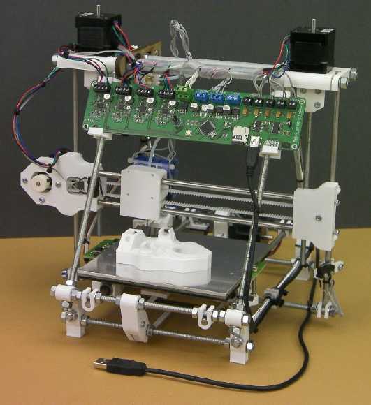
Instead, an open source 3D printer revolution was started
by a developer in London about 2007, and it started catching on.
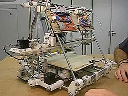
reprap mendel 3D ABS/PLA plastic extruder-printer
I also read about a plastic I hadn't heard of before,
"PLA" or "Poly Lactic Acid", made from plant material such as corn
starch, tapioca or sugar cane instead of petroleum products. The
machines I'm interested in can use either ABS or PLA.
SO! Forget injection molds entirely: the plastic parts for
my version of the Turquoise Battery can be made with 3D printing
technology. The writer in The Economist was right - certain
things that were hard until now have suddenly become a LOT easier.
Battery making may be the second thing revolutionized by 3D printers.
Regardless of chemistries, printing electrode containers
and other battery parts will make homemade batteries practical for the
first time. After all, a battery is just chemical powders, crammed into
"+" and "-" housings, with some sort of current collectors connecting
the chemicals and all immersed in or containing some sort of
electrolyte. Cramming chemicals is simple - appropriate structures and
current collectors to cram them into constitute the hard part.
In fact, the thing will have other uses as well: for
example, custom made LED light fixture bases for various styles of
diffusers would simplify LED light construction and they could be made
easy to screw into walls and ceilings without even removing the
diffuser. For another example, anchors and mounts for various things
like the terminal blocks in the motor controllers and in the "DC Grid
Tie" units.
On the 9th I ordered a complete kit for a somewhat smaller
model, www.REPRAPpro.com/Huxley . It's expected to ship July 20th. Work
area is 140 x 140 x 110 mm.
REPRAP Huxley as made in kit form by RepRapPro
I seem to usually be in the next-to avant guarde in
printer technology. Interestingly, The Huxley is similar in dollar
price to the first mass market dot matix printer, the Epson MX-80
(1981?), and to my first color inkjet, the original Epson Stylus Color
(1992?). And half the price of my first laser printer IBM4029, similar
to original HP Laserjet (1993?)
(My first color laser printer, the Samsung CLP-300, was much less than
any of the others above - I must have been late getting in.) Back then,
each dollar was worth
substantially more than it is now, so in effect, 3D printing is the
cheapest new printing technology yet - and look what it does!
There were also additional recent designs: the Ultimaker
(Holland) and the Solidoodle (USA). Ultimaker is evidently
faster but costs more, and it looked like Solidoodle (cheapest... and
pre assembled) isn't ready to ship yet.
3D printing can make parts that previously only injection molding could
- and more.
Electrode Pockets from VICAMP
Meanwhile, I had contacted VICAMP about making some
ABS electrode pockets with their machine, both as potential alternative
production and to get some soon instead of maybe by next fall. The
REPRAPs have a heated table. The VICAMP machine keeps the part in an
enclosed 'oven' space closer in temperature to where the plastic
softens, which makes parts that stick together better and warp less. It
can print polycarbonate and ?"ulton"? - similar to nylon) as
well as ABS and no doubt PLA. (Polycarbonate and Nylon... I start
thinking of planetary gear/torque converter parts!)
I had had the idea of making the pockets lying down, in
two halves to butt together and glue. (For that, the heated table
should
be sufficient.)
______
| |
|_____|
The VICAMP maker came up with a slightly more elaborate
design where ideal alignment was assured:
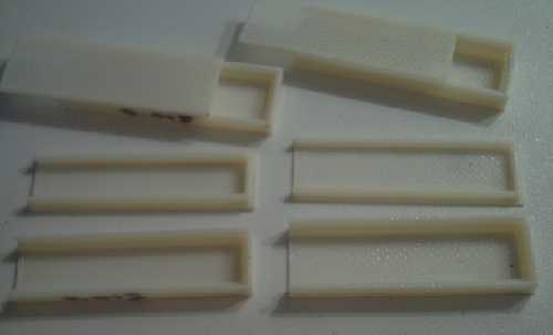
First batch of open ended "boxes with lips" pockets from VICAMP.
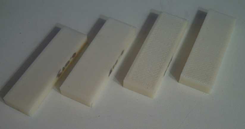
pocket 'boxes' as assembled showing closed bottom end.
The mesh of the ones on the right seemed too coarse - the chemicals
might come out.
Only the narrower one (@ 1/2" vs 3 @ 5/8") one on the left was stiff
enough to consider using.
From this design, I came up with the idea to have one half
fitting over the other:
______
| |
|____|
These would glue together along the 'verticals'. The sum
width of the adjoining vertical walls could still be strong even when
made narrower than the walls butted together or in the first 'box'
form, wasting less plastic and adding less size and weight to the cell.
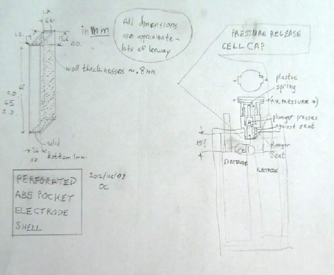
A second batch of pockets all looked usable, altho several
different patterns, wall thicknesses and internal thicknesses had been
created. The thin ones looked almost like my text drawing above.
I wrecked one of the boxes. I put too much methylene
chloride on to glue the halves together, and some spread onto the mesh.
The perforations in the mesh filled in, and simply touching the mesh
while it was wetted broke it and left two jagged holes. This however
led to
the realization that the slightly porous printed parts, to use them for
cases and pressure caps, could be sealed simply by a quick application
of, or a dunking in, methylene chloride.
I think the cases can be printed square "U" shaped bottom
and
ends, while the wide sides can simply be pieces of flat ABS sheet glued
to the "U"s. The fairly precise control of dimensions printing the "U"
and
the matching glue-on lid will make the cases relatively simple to
fabricate and assemble.
Or the whole open top case might be printed as a unit.
However if it needs to be saturated with methylene chloride to seal it,
it might not be as much easier as expectable. This might still be a
good place for an injection mold.
Next Mn Negode
Having obtained pockets for electrodes, zinc collector
plates, and manganese carbonate, I decided to to make the manganese
monoxide with heat:
MnCO3 → MnO + CO2 - at 200-260ºC.
As an aside, another way to convert the carbonate would be
by making the electrode and soaking it in [dangerous] NaOH or KOH. This
exchange reaction makes Mn(OH)2 + Na (or K) CO3 - a contaminated
electrolyte to dispose of. (as garden fertilizer?) The heat method is
preferable IMHO if it does an acceptable job.
The surprisingly low temperature can be had in a kitchen
oven set to 450ºF or 230ºC. The one problem with it is that
without an inert gas facility, the MnO readily absorbs oxygen from the
air to form
Mn3O4 or Mn2O3. That's at least less oxidized than MnO2, but I could
derive it from MnO2 with a higher temperature. I put it in a
crucible and put aluminum foil over the top. Perhaps the CO2 would
drive the oxygen out of the crucible?
I put 100g of MnCO3 [valence II] in the crucible. The
results should be indicated both by the color and the weight after the
CO2 is driven off:
MnCO3 - [II] light pink - 100g
MnO - [II] green or "dark colored" - 62g
Mn(OH)2 - [II] white - 77g
Mn3O4 - [2.33] red or brown - 66g
Mn2O3 - [III] dark brown or black - 69g
MnO2 - [IV] black - 76g
Short duration
heating in the kiln (on the 17th, 15 minutes?) with the powder in the
crucible and
aluminum foil over the top resulted in 97 grams with brownish powder
around the outside, still pink in most areas.
I decided to put it in a small stainless pot in the oven
at 425ºF/220ºC, still with aluminum over the top, for 90
minutes. It looked about the same and weighed 97 grams.
I tried again with the oven at 460ºF. This time, the
whole mix turned a medium-light brown - perhaps about right for Mn3O4.
But it still weighed 96.4 grams. Surely it should at least drop below
70!
Next try was at the oven's highest setting,
500ºF/260ºC. 260ºC is where it's supposed to start
forming Mn3O4 or Mn2O3 instead of stopping at MnO at all. But I'm
beginning to think the oven temperature is a little below the dial
setting, at least up near the high end. But the weight was still 95
grams.
On the 19th I tried putting it in the new crucible and
torching
it. (It was so windy on the 18th I waited a day.) The top glowed
red, but I realized it wasn't heating very deep in. So I dumped it out,
aimed the torch into the crucible, and started sprinkling the powder in
with a teaspoon. The torch not only heated the crucible, but also the
powder as it fell past the flame. This time the powder, still medium
brown, was down to 85 grams. I repeated the process and got about 72. I
repeated it a third time and it was down to 59 grams. I figure probably
about 2-4 grams was lost in all the handling and sprinkling. However,
in the reducing propane flame and seeing the low end range of the
product weight, I figure it probably formed either MnO or Mn3O4, or
some of each, rather than higher oxides. Or it may in fact even have
formed some metallic Mn. To my eyes it's medium-dark brown with no hint
of green, but I'll call it a success. (Would it turn white in
water, converting from MnO to Mn(OH)2)? Hmm... not in clear water.) I
was surprised that in all this torching, the torch flame didn't seem
to be blowing any notable amount of powder away from or out of the
crucible.
If I'm going to torch it anyway, I might as well be
starting with MnO2, which should also reduce to MnO in the torch flame.
With either substance, if this is how it's to be done, I should set up
a stand for the torch and some sort of funnel pouring system that'll
automatically drop out an 'hourglass' sort of fine sprinkle of powder.
Without 'clumps' of powder going by it'll probably just take a single
pass through the flame.
With that at last ready to go (on the 20th), the negode mix could be
formulated:
MnO active chemical - 80% (32g / 32.6)
Zn conductivity enhancer - 20% (8g / 9.4)
Sb2S3 hydrogen overvoltage raiser - 1% (.4g)
For the electrode pocket, I selected the (only) 4.5mm
thick one from batch 2, with .042" (1.05mm) thick faces, 4.65 grams. It
was quite stiff with little flex. The 'lid' sides were all the same
shape, but I forgot there were a couple of non-perforated ones until
after I'd glued it on. Nevertheless, it seemed to be 'microporous'
(evidently typical of printed ABS parts), which is probably good enough
-- maybe it's even better, saving the trouble of putting in a separator
sheet or spacers. I can hardly wait to get my own 3D printer to try out
variations.
 I had cut the
zinc current collector (2.25g) about the end of May;
now I made a 2mm thick aluminum spacer to put in while the first side
was filled. The next day I made the mix, wetted it, and stuffed it in.
I had no particular system set up, and it must have taken an hour of
dropping a bit of mix on the zinc plate and stuffing it in with a
'plunger', ad infinitum, then repeated for side two. The zinc current
collector 'tab' was bent a few times and the tip broke off in all the
stresses. The mixture, with no binding agents, was loose and not
amenable to good compaction. It mushed out around the plunger, even tho
it wasn't very wet. Zinc makes initially very fragile electrodes; this
seemed as bad or worse, and worse than the sintered one.
I had cut the
zinc current collector (2.25g) about the end of May;
now I made a 2mm thick aluminum spacer to put in while the first side
was filled. The next day I made the mix, wetted it, and stuffed it in.
I had no particular system set up, and it must have taken an hour of
dropping a bit of mix on the zinc plate and stuffing it in with a
'plunger', ad infinitum, then repeated for side two. The zinc current
collector 'tab' was bent a few times and the tip broke off in all the
stresses. The mixture, with no binding agents, was loose and not
amenable to good compaction. It mushed out around the plunger, even tho
it wasn't very wet. Zinc makes initially very fragile electrodes; this
seemed as bad or worse, and worse than the sintered one.
Starting with 10 grams, I had less than 2.5 remaining, so
about 7.5 must have gone in. The MnO was about 79% of that, so 5.9g of
MnO. The "O" dilutes pure Mn's .975 AH/g, yielding about 4.4 AH
theoretically. If the bulk of that proves accessible for discharge, it
should be quite good, but for production I'd like to see more Mn
compound and less extraneous structure if possible.
I put the electrode into the Changhong cell with its
nickel electodes, with a piece of watercolor paper folded over it. The
leed barely stuck through the top to make connection to, and that by
pulling it up a bit. Initial voltage was 1.7 something. After a few
hours charging at ~50mA, it sat at 1.84.
Charging voltage, instead of rising, started at 1.92 and
dropped to 1.905, and stayed around that level some hours even as the
off-charge voltage rose... then it dropped further to 1.895 with an
off-charge voltage of 1.85. Hopefully, that meant that the electrode
was building current bridges and oxide was becoming more conductive Mn
metal.
With a 2.2 ohm load, output dropped below about 1.2 volts;
1.25 volts after a few hours; then almost 1.3 when the day was done.
The next morning, it had improved to 1.87V open circuit
and 1.4V with the load. But I opened the cell and found an 'erupted'
pile of light gray material had oozed out of the electrode. Well, it
made sense that Mn(OH)2 should take up more room than MnO, and white
Mn(OH)2 would explain the light color. Perhaps I shouldn't compact it
much at all, and just let this swelling do its work? I scraped it off
and let it fall into the cell. I'd have liked to look at the whole
electrode to see if the sides were bulging or if it was also oozing out
the perforations, but that would have meant disrupting everything, and
I also dislike working with caustic KOH, so I left it for later, when I
would also change the electrolyte, since it might have a fair bit of
carbonate in it by now from any leftover MnCO3, plus the sludge on the
bottom. If any was oozing out, the paper I had put in should prevent
shorts. The nickel electrode was bubbling (oxygen) since it was already
charged and the charging current continued. The Mn side only bubbled a
bit.
After another couple of hours, the charging voltage
started going up, and I had to reduce the current to 50mA again. It
seemed much too soon. Was the zinc plate disintegrating? I had pulled
it out a bit when I inspected, and it came up disturbingly easily
through chemicals it was supposed to be in minute contact with. Would
this electrode deteriorate and become useless like so many others I'd
made? No load voltage was up to 1.87, and a 2.2Ω load test delivered
above 1.5 volts -- but dropped off with passing seconds, indicating
poor connections through the electrode. Probably disturbing the current
collector upset things?
1.88 volts seemed too high to be zinc [+.49 - -1.28 =
1.77V], but not really there yet for manganese [+.49 - -1.56 = 2.05V].
 On the 23rd I
opened the case and removed the electrodes. More mix had evidently
oozed out the top around the edges of the pieces of plastic I inserted
to prevent this, and seemingly also through the tiny perforations - but
only on the side with the intended perforations. The 'microporous' side
was clean. Evidently, the powders being very fine, microporous is the
way to go - and a good fitting glue-on lid would be a definite asset.
In fact, it seems to me Alkaline Storage Batteries mentions a
special Ni(OH)2 mix for flooded pocket electrode cells - I bet it's a
specially coarse mix to minimize oozing. And they do anyway. They have
to have it rinsed off before final assembly. Being able to print very,
very fine perforation - more like 'pores' - will be a definite 3D
printer technique asset over punching holes in solid pieces.
On the 23rd I
opened the case and removed the electrodes. More mix had evidently
oozed out the top around the edges of the pieces of plastic I inserted
to prevent this, and seemingly also through the tiny perforations - but
only on the side with the intended perforations. The 'microporous' side
was clean. Evidently, the powders being very fine, microporous is the
way to go - and a good fitting glue-on lid would be a definite asset.
In fact, it seems to me Alkaline Storage Batteries mentions a
special Ni(OH)2 mix for flooded pocket electrode cells - I bet it's a
specially coarse mix to minimize oozing. And they do anyway. They have
to have it rinsed off before final assembly. Being able to print very,
very fine perforation - more like 'pores' - will be a definite 3D
printer technique asset over punching holes in solid pieces.
After rinsing the electrodes and knocking the stuff off, I
put the battery back together. (I didn't change the electrolyte.)
Obviously this not so well compacted 'loose fill'
electrode was nothing like as conductive as the previous sintered
electrode, but it did gradually improve over the hours as it charged.
I'll be thinking of how to do this all better. The 'microporous'
plastic side may (just possibly) have limited ion flow to that side.
Perhaps a good way to make Mn(OH)2 would be electrical
reduction of MnO2 - to discharge it as a negative battery electrode
reaction, but stopping when it hit -.15 volts instead of trying to
charge it to -1.56. The Mn(OH)2 at least shouldn't expand after the
electrode is assembled.
I finally woke up to the fact that the 1.8 volts that
seems to be as high as wants to stay charged to is roughly the voltage
of NiZn, not NiMn. Reaching 1.9 volts can be done, but the Mn doesn't
stay charged and it drops back to 1.8.
At this point, I began to think that Mn negodes don't work
in KOH electrolyte because the voltage (-1.56) is too high even with
antimony sulfide added. They do seem to work in my 'moderately
alkaline' cells, perhaps because the voltage decreases more rapidly
than the alkalinity to -1.18V. (Zinc drops to under a volt in these
conditions. But NiOOH and KMnO4 both go up faster with falling pH, so
the overall voltage is higher.)
I also keep looking at that zinc pourbaix diagram that
shows no soluble state between pH 8 and 13 - the desired alkalinity
range. Accoring to theory, that should mean zinc won't form dendrites
at those pHes, in which case it would make a very good negode material
producing roughly 2 volts open circuit. I'm not convinced it would
actually work that way and make very long life electrodes... but it
looks like it on the chart, so it might.
That the Ni-Mn/KOH cell won't charge Mn to metal meant the
next step should be to make a complete Mn-Mn/KCl cell to repeat for
verification the successful chemical results of February, but with the
new current collectors/terminal leeds to hopefully get better
conductivity.
 I used
the KMnO4 posode from April (with one pocket nibbled off and tiewraps
to hold it closed) and the Mn negode pulled from the Changhong cell
(still oozing stuff). Another bit of the zinc terminal tab broke off
and I had to make do with such a short length that even coming close to
sealing the cell looked problematic. I did what I could.
I used
the KMnO4 posode from April (with one pocket nibbled off and tiewraps
to hold it closed) and the Mn negode pulled from the Changhong cell
(still oozing stuff). Another bit of the zinc terminal tab broke off
and I had to make do with such a short length that even coming close to
sealing the cell looked problematic. I did what I could.
Conductivity was very poor and the water turned purple
(sigh!), but sure enough, even with only 8mA charging current, in KCl
it immediately started charging to well over 2 volts, too high to be
accounted for by the permanganate-zinc (~+.95 - ~-1 = 1.95). Only
permanganate-manganese (~+.95 - -1.18 = 2.13) would explain the high
voltage. After a while it hit 2.25 volts. There was still some self
discharge, whereas it seems to me that in February I had pretty much
eliminated it.
Then it occurred to me that with the cell being poorly
sealed, oxygen would get in. If oxygen would discharge MnO to Mn3O4, it
would surely discharge wet Mn to MnO or Mn(OH)2 in spite of the
antimony. In fact, it discharges cadmium and metal hydride - that fact
is used to keep dry cells from bursting on overcharging or too rapid
charge. That probably explains all residual self discharge. It would
seem that alkaline cells must be essentially sealed to hold
their charge, with of course the high pressure release.
Evidently I've been wasting my time
thinking that Changhong could make the chemistry work with their
existing flooded KOH alkaline cell production line. It seems to need
the carbon parts, salt electrolyte... and likely a somewhat better
sealed case than theirs. Again it seems fortuitous that somehow I
didn't convince them to try it out. When I can send them a finished,
working battery I'll do that and see what they think.
It's probably time to set
the battery project aside until August or September when the 3D printer
arrives and is assembled (except maybe for a bit of preliminary 3D
electrode pocket computer modeling). Then I'll be able to easily do
things that have proven difficult - even problematic - so far: ideal
plastic pockets, and 'slight-pressure' cells with caps that don't
leak... or even cells that don't leak.
Conductive perforated plastic electrode pockets!
Since I had ordered the 3D printer, I started looking into
sources of ABS plastic. I was informed there was a conductive
ABS printing filament! I explained that it would have to be conductive
carbon or graphite based for the positive electrodes, or conductive
zinc
based for the negatives, and that nothing else would work.
It turned out the conductivity was based on carbon fiber!
This could revolutionize the position. Instead of grafpoxying a thin,
narrow 'sheet' of carbon fiber for each electrode and sticking it into
the middle, then having to compact powders on each side of each one
separately, the electrode can be printed as above but with a connection
tab to stick up through the case. Stuffing would be one simpler
operation instead of two more fiddly ones. In fact, a whole set of
pockets forming a plate with a tab could all be printed at once.
It would all depend on how conductive the ABS really is --
or could be made to be with toluene, osmium/aldehyde, grafpoxy or
whatever. Of course I put some on the order - it was just becoming
available, a new product. But it would probably arrive before the
printer.
In addition, the person said he would consider trying to
make conductive zinc ABS filament as well. This doubles the excitement!
Certainly one couldn't pull the terminal leed and disturb the
connections if the basket was the current collector. 3D
printing, with conductive printing filaments of the exact
formulations required, might just solve nearly all the battery
production problems at a stroke! However, I might have to pay something
up front as an inducement, and of course the endeavor might not
successfully produce a practical material.
The big advantages would be:
* The pockets would be printed automatically, sizes, shapes and
material as desired. This alone saves a heck of a lot of work. (If
printing 3D parts is too slow for production needs... get or make some
more printers!)
* The printed pockets would have attached printed terminal leeds
exactly sized and positioned for the holes in the lid of the cell, with
all the pieces liquifyable by methylene chloride. The cell would thus
be much simpler to assemble and to seal.
* The mass of these non-reacting 'extraneous supporting structures'
that reduce the energy density of the electrodes could (I'm sure) be
reduced somewhat.
* The electrodes would be easier to fill and compact the powders into
-- again saving a lot of labor.
Later he said that for all the hype, he had been unable to
get the conductive ABS from the supplier to make into filament. Now I'm
trying to think of other ways of accomplishing the same sort of thing.
2-piece pressure caps?
I had considered the pressure cap a being something that
would screw into the lid of the cell. As such, it would need a bottom
piece, a threaded-on top piece, and a 'plunger' or other shape of
sealing piece. But the bottom piece could be printed right into the lid
of the cell as part of the lid. The top piece would be unscrewed for
access to the cell. The main disadvantage I can think of offhand would
be that the plunger would need a much larger sealing seat to give a
sufficient hole for access.
Mn: a really economical, green battery chemical
Surprisingly I read:
"Together with manganese sulfate, MnO is a component of
fertilizer
and feed additives. Many thousands of tons are consumed annually for
this
purpose."
Surprisingly... because how - and why -
do they keep MnO from oxidizing to a higher oxide when it seems so hard
to prevent? I suspect a glitch in the writing here somewhere. Anyway,
such widespread, and agricultural, uses of manganese compounds indicate
both their economical and environmentally friendly character.
http://www.TurquoiseEnergy.com
Victoria BC