Turquoise
Energy Ltd. News #54
Victoria BC
Copyright 2012 Craig Carmichael - August 4th, 2012
www.TurquoiseEnergy.com
= www.ElectricHubcap.com
= www.ElectricWeel.com = www.MushroomOutboard.com
Hilights: Peltier Element 12V Refrigerator
Month In Brief (Summaries)
- Solar - thermo-electric fridge - Thermomagnetic theory supported by
ambient heat powered battery.
In Passing (Miscellaneous topics
and editorial comments)
* Machines have increasingly done the grunt work for decades. When will
labor saving devices finally start to shorten
everybody's working hours?
* "Normalcy Factor": populations caught by surprise in changing times.
* Solar PV Kickstart in Germany (next: Ontario Canada): paying
extra for solar power to grid has caused homeowner installations that
eliminate need for other new power plants.
Electric Hubcap System
* Plasticy primer prevents ilmenite coil coatings from flaking off
(yay, at last!)
Planetary Gear Torque Converter
Project
* EDM Machining of sun gear: keyslot made - can now get on with Sprint
car motor/converter installation.
Solar Electricity Project
* Power Price Point (probable power cost increases may soon make solar
economic)
* PV Solar Panel roof mounting, connecting - fuses, isolation diodes,
breaker.
* Spinoff project: Superinsulated Thermoelectric Fridge & Freezer
* Voltage: 24 volts would be great, but most appliances are 120VAC - or
else 12VDC.
* Max Power Point DC to DC converter/CV charge controller/dump load
driver unit?
* Cases for multiple voltages & 3D Printed Plastic 12V D Cell
battery cases?
Superinsulated Thermoelectric Fridge &
Freezer
* Shallow chest format with hinged lid (or lid sections)
* Peltier cooling elements & 12VDC cooler cooling module
* Peltiers in thermal series; peltier module heat pump/heater; two-stage
peltier
makes
frost in room temperature environment
* Exploring Insulation; Construction / Bill of Materials /
Tests during construction
* Conclusions & Product Possibilities: TE temp. control; TE 2-stage
peltier cooling unit; TE Fridges; TE Heat Pumps
LED Lighting Project
* Linear, low dropout voltage, constant current regulator gives supply
voltage flexibility.
* Circuit board production: laser printed artwork iron onto board;
novel etching solutions.
* New way to make printed circuits boards?: artwork is thin
layer of 3D plastic (or wax?), 3D printed
directly onto the PCB?
Turquoise Battery Project
* 3D Printer kit arrives - 3D Printer Software / Conductive ABS
printing filaments / Zinc flakes / Osmium
* Recharge with ambient heat energy?
No Project Reports on: Magnetic Motion Devices, Weel
motor, DSSC
solar cells, Pulsejet steel
plate cutter
Newsletters
Index/Highlights: http://www.TurquoiseEnergy.com/news/index.html
Construction Manuals and information:
-
Electric Hubcap Motor - Turquoise Motor
Controller - 36 Volt Electric
Fan-Heater
- Nanocrystalline glass to enhance Solar
Cell performance - Ersatz 'powder coating' home process for
protecting/painting metal
Products Catalog:
- Electric Hubcap Motor Kit
- Sodium Sulfate - Lead-Acid battery longevity/renewal
- NiMH Handy Battery Sticks, Dry Cells
- LED Light Fixtures
Motor Building
Workshops
...all at: http://www.TurquoiseEnergy.com/
(orders: e-mail craig@saers.com)
July in Brief
Near the start of the month, I finally found a plasticy
'undercoating' for the motor coils
that the ilmenite in sodium silicate doesn't readily flake off of. I
then thought to put together a couple of motors and controllers and get
the Sprint car going and be ready to power the Mushroom Outboard, but
only one motor got partly done.
I soon got enthused about
the idea of a 12 volt
superinsulated 'shallow chest' fridge using a peltier module for
cooling. The fact that
there are few home products like fridges and freezers made to operate
on low voltage DC is doubtless hindering adoption of off-grid and low
voltage solar energy systems. This would begin an exploration of this
area and the products that might be created to fill the gaps.
Telling
myself that I already had more projects on the go than I could complete
didn't help. I figured it
would be a short project. It won't drag on for years, but it did occupy
much of the rest of the month after the solar panels were up, and it
still isn't finished. I ended up with a camping cooler peltier unit
complete with fans, as it looked tricky to outfit a peltier cooler from
basic parts. Over a few
days I got as far as buying the main ingredients and cutting styrofoam
insulation pieces (R5 per inch) to form the main body. I got
polyurethane foam mix for the inner inch, as it has about the highest R
value (R6-R7) of anything except a couple of unobtainables: vacuum
(R30-R50)
or aerogel ("solidified smoke" - R10). It took much longer than I
expected to foam it in, and if I was to do it again I'd probably stick
with premade sheets and just get one can of polyurethane spray foam to
glue the pieces together. In spite of the great insulation, I could
only get the 4.5 cubic foot space down to 9ºc. This got to be a
puzzle as adding insulation didn't help. It finally proved it was the
cooling unit that would only drop the temperature by about 13 or
14ºc
regardless of what it was mounted in including the original cooler. I
needed to buy or make something better. On the 31st I tried setting up
a 2-stage peltier unit, and It made frost on the coldest part, right in
the warm room. So the temperature is attainable, and the question is
simply how big a unit using how many watts will be needed to cool the
whole fridge - it might need up to 100 instead of 60 or 70.
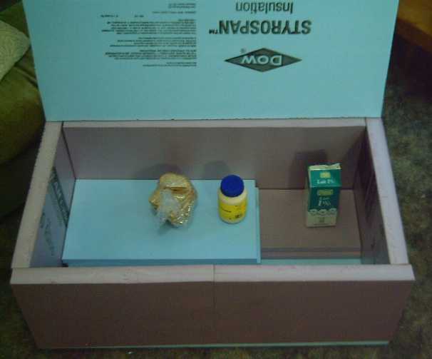
Fridge with lid and coverings removed, showing the 3+" insulated walls
and floor
The solar panels put out
thirty-odd volts (presumably at up to about 30 amps). On the 14th I was
loaned a 20-48V to 14V DC to DC
converter. The next day I got one of the panels wired up, adjusted the
converter to 13.8 volts, and tried it out with a NiMH battery that
needed charging.
It worked fine as long as the solar panel wasn't
overloaded. It wasn't putting out much power in the overcast, and
pressed beyond its maximum power point, its voltage dropped off. Then
the converter started making scary noises and actually started drawing
heavy currents from the battery. Then I realized that for sure
I wanted to make a flexible, multi-purpose unit specifically for solar
panels that would properly handle all situations. I think that would be
great merchandise, and relatively simple to put together. (There's even
a machine shop near here that is looking for products to assemble,
which is getting into electronics assembly... hmm!)
Further considering solar and battery power for homes
brought me back to LED lighting. My units are very simple, but they
work at exactly 12.0 volts. Battery power can vary from a little less
than that to over 14, which would blow the fuses in the LED lights. I
came up with a simple linear circuit (just one
transistor!) to provide constant current to the LEDs for any voltage
from about 12 up to 15 or 16. At almost 13 volts it's still about 90%
efficient,
which is better than most 120VAC switching power adapters.
That got me going on making
PCBs. I now wanted several simple ones for various things, along with
the more complex ones for motor controllers.
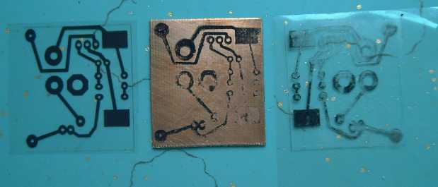
I hadn't done a photo PCB board in 25 or 30 years, and I
had no intention of getting back into that laborious process. I had
heard of printing the artwork on a laser printer and then ironing it
onto the PCB. The first try was crap. The second one, after more
carefully cleaning the copper with solvent, made a somewhat workable
board and I etched it.
Then I got the idea
to try printing etch resist artwork directly onto
printed circuit board copper with a 3D printer. Assuming it works, it
should be a reliable, repeatable in-house board production technique --
unlike anything else I've found
so far.
An e-mail on the
22nd advised me my RaprapPro[.com] Mendel
3D
printer had been shipped. It arrived the next afternoon. It is of
course a fairly
complex kit, yet to be assembled. Once it is, I should be able to start
improving my methods of making various things, starting with alkaline
batteries and circuit boards.
Bases for LED lights, complete with vent holes and
mounting bits for everything, would also be a great simplification and
I could charge less for the lights.
Evidently my theory of "thermomagnetism", that magnet
machines can self power from nothing more than the ambient heat within
the
magnets, has a parallel. Ambient heat in a solution has apparently
been used to make a self powering battery. The vibration of molecules
in the solid magnet is replaced by the travels of copper++ ions in the
solution.
Six cells in series will light an LED, suggesting they're about 1/3 of
a volt each. However, the article leaves much unexplained, and the
author
is somewhat skeptical:
http://www.technologyreview.com/view/427140/graphene-battery-turns-ambient-heat-into-electric/
Graphene Battery Turns Ambient Heat Into Electric Current
"Physicists have built a graphene battery that harvests energy from the
thermal movement of ions in solution"
<snip>
"So the energy generated by this device comes from ambient heat. These
guys say there were able to increase the current by heating the
solution and also by accelerating the copper ions with ultrasound. They
even claim to have kept their graphene battery running for 20 days on
nothing but ambient heat."
Some of the comments underneath the
article showed some keen thought by readers.
For example, "Yes it breaks the laws of thermodynamics but those
laws
may break down
at atomic scales, just as newtonian physics breaks down approaching the
speed of light."
Interestingly, the graphene may be
comparable to my doped graphite positrode current collectors, and I can
easily add copper chloride (their magic electrolyte) to my cells. It's
left over from etching printed circuit boards. Might that make them
charge themselves or give off current even when supposedly discharged?
Intriguing!
In spite of the little time spent working on the Sprint
car, motor and torque converter, another hurdle (besides the ilmenite)
was overcome. The sun gear of my planetary gear set had no splines,
keyslot or other mounting devices - just a 1.064" shaft hole. At a
Saturday brunch I learned someone near me had an EDM machine. That
meant nothing to me. Then, conversing on a list, I learned EDM can
machine case hardened parts such as my sun gear. I took the gear to the
shop at the end of the month and had a keyslot cut into it. I can now
proceed with getting it mounted on the motor shaft and putting the
motor together, and getting the car going.
In Passing
Incidental news, editorials
Shorter Working Hours
I have advocated shorter working hours for almost my whole
career. It has always seemed to me that there are two categories of
people: those who are unemployed and have no money, and those who are
who have no spare time to relax and enjoy the fruits of their labors,
be with family,
or engage in creative endeavors. I've been at both extremes. Where is
the middle ground? Why do we
live these unbalanced lives?
In an advancing age of machines that do more and more of
our "grunt" work for us, we should be actively seeking to address this
imbalance by shortening the work day, perhaps to 6 or 5 hours - maybe
even 4, while we absorb the unemployed but employable into the ranks of
the working. The "unemployable" group is bound to shrink when we
aren't pushing everyone like slaves into working such long days, and
worker productivity per hour over five hours will doubtless be
substantially higher than when people are forced to work eight or
more. Even in the 1970's at my first job, it seemed to me machinery and
technology were liberating people from drudgery, and that it was silly
to be working long hours when there was less of it to do. Every passing
decade has made that more true.
Many grumble that they wouldn't be able to afford to live
if they worked a shorter day. Aside from an aside comment that many
people
seem to live more wastefully than is good for them - often to the limit
of their means when times are best for them, which sets them up for
trouble at the first income glitch - consider that if everyone
is
working shorter hours, then everyone can afford about the same
lifestyle as everybody else. House and other 'big ticket items' prices
will adjust. Taxes will go down when more are contributing and fewer
need assistance.
People will have more leisure time to devote to family, to
creative
endeavors, or to contribute in many ways to an advancing society. We'd
all be much better
off.
Are we there yet?
"To enjoy privilege without abuse, to have liberty without license, to
possess power and steadfastly refuse to use it for self-aggrandizement
— these are the marks of high civilization." - the Urantia Book
The "normalcy factor"
A video on you-tube mentioned something called the
"normalcy factor" or "normalcy effect". When some crisis that hasn't
happened in living memory is looming people tend to say "that's
ridiculous", since it "never has before", or is
something "from history". "Today things are different - it can't
happen." So they don't prepare, and they suffer
needlessly for that lack of preparedness.
The movie gave as an example the sufferings of the jews in
nazi Germany. Of 450,000 jews in Germany in 1933 when Hitler came to
power, 100,000 fled by 1935. Even in the face of everything, the rest
thought it was a glitch, and that everything would surely soon return
to normal. It was impossible Hitler wanted them, good germans all,
dead, or that such a thing would be allowed. It defied 'normalcy'. It
was the factor that kept them from taking timely measures for self
preservation.
Preparing for a fiat currency crisis and grocery store
lineups is much easier than fleeing your homeland, and need not disrupt
normal life. If nothing happens, you've done nothing harmful or
disruptive. If things return to "normal" after a relatively brief
crisis, you've saved yourself from temporary hardship. If 'abnormalcy'
becomes long extended, your preparation buys you time to make new plans
and help work out some new techniques of making a living and doing
business before you're desperate.
The future isn't usually for us to see very far or clearly
into, but
dramatic financial trouble appears imminent and it's said it was just
staved off in 2008. Some European
nations are already falling into a pit. Greece in particular has fallen
under harsh occupation by the IMF and is being pillaged, its assets
stripped for pennies on the dollar, by "financial weapons of mass
destruction". (Steve Forbes was seen there in June, cashing in.) It's
no longer a nation with power to control its own destiny. And the
banksters are working on Spain,
Italy, and Ireland. Even here in cities like Victoria, Canada, it looks
like politicians have been bribed by banksters to facilitate pillage of
local populations via needless "sewage treatment" projects in a manner
similar to Jefferson county, Alabama, which had to declare bankruptcy
last year, and where residents can't afford to turn on their taps or
flush their toilets. Corruption, collusion and fraud at the highest
levels has become rampant and everything is now heading inexorably in
the same direction. Former British PM Tony Blair is now a JP Morgan
Bank executive. Who then will arrest the banksters and reverse this
tide? How can the dam not break? What happens after that is much
less
clear.
From another perspective, societies are as strong as their
families, and family life has been breaking down for decades. Why would
societies remain 'normal'?
Subsidies kickstart conversion to solar energy
(As told to me, later affirmed by a second person...) It
seems Germany has been subsidizing adoption of solar energy by paying
homeowners 10 times the going rate for solar generated electricity. I
don't know the exact details, but evidently the offer has caused so
many conversions that there's now the equivalent of two nuclear power
plants operating on German city roofs. And evidently Ontario Hydro is
now adopting the same incentive scheme. Perhaps BC should do the same
instead of spending 8+ billion dollars (2000+ $/person) on the Peace
River Site C dam?
Electric
Hubcap Motor System
Longstanding motor making problem solved: 'Plastic Dip' "primer
coat" prevents flaking of the ilmenite in sodium silicate
paramagnetic coil coating
The motor coils, after all this time, still needed the
paramagnetic coating to adhere and not flake off. I put small,
occasional efforts into the problem - whenever I put a new motor
together, which was rarely. Since I need at least a couple of motors,
here was another occasion.
Industrial Plastics had a rubbery plastic dip or spray. I
have no idea what it is - maybe some sort of PVC. It stinks of toluene
solvent. I
bought a can of the dip on the 5th and dipped a coil in it. It was too
thick (IMHO)
and made quite a thick, globby coating on the coil, where I wanted a
thin primer coat to paint the silicate onto. I wiped some off while it
was
wet, and it came out pretty nicely. (My main objection to 'thick' is
that it's extra thermal insulation to cause the coil to get hotter
under
load.)
Then I mixed some ilmenite and sodium silicate and painted
it on. It beaded up, just about like on the epoxied wire and the coil
core. Unlike on them, it stayed attached after it dried.
Then I started to think... the general ceramic
recipe is
nanocrystalline magnetic particles suspended in a glassy substrate -
hence the sodium silicate "water glass" substrate. But was it just a
neutral medium for the powder, or was it part of the reason it worked?
If the former, wasn't rubbery plastic also a neutral medium? And the
rubber looked like it was staying on the coil.
So I mixed some ilmenite into some of the dip, thinned it
with toluene, and painted
this "plasticized ilmenite" onto a coil. I liked brushing better than
dipping - no fat blobs. (I rolled the brush up inside a plastic bag and
put it in the freezer to keep it soft, since I knew I'd need it again
soon. It worked for a few days.) I wasn't confident the magnetic effect
would work, or
work as
well, as with the sodium silicate, and I wasn't willing to divert into
motor performance testing to find out at this time. It looked good and
wouldn't
flake off, but the next morning I painted a coat
of ilmenite in sodium silicate on top of it. This beaded up, but
somewhat less.
Then I painted a coil with the plasticized
ilmenite, hung it by its wires inside the bag of remaining
ilmenite, closed the top of the bag, and shook it around. Now I had a
coil painted with the plasticized ilmenite and with a dry powdery
ilmenite coating.
Some of the dry particles would be stuck to the plastic but sticking
out,
for the sodium silicate to adhere to. That way, the ilmenite particles
would create a bond between the plastic layer and the silicate layer. I
painted it with the silicate in the afternoon, and it went on very
nicely - no beading or gaps.
Meanwhile, altho the silicate had beaded up on the
previous one, the
coverage was better, and on none of them (even the plastic with no
ilmenite) did the silicate layer tend to flake off. I gave the second
one another coat of silicate, and by evening they were both dry and it
was evident I had two good coils.
So I put another coat of silicate on the first coil as
well. It still beaded up and wouldn't cover. Oh well.
The most intractable problem with making the motors
appears to be solved. There may be any number of good 'primers' that I
haven't tried, but the 'rubbery' plastic coating with ilmenite mixed
in, then preferably dusted with ilmenite powder while it's wet, seems
to work. I'll take it!
Planetary Gear Torque
Converter Project
EDM Machining for Case Hardened Gear
I'd been wondering how I'd get the converter's case
hardened sun gear mounted on the motor shaft. It had only a shaft hole:
no keyslot or set screw holes. It was one reason for "procrastinating"
on getting the Sprint car going.
Then I found out a machine shop near me had
'electromagnetic discharge machining', EDM, which meant nothing to me.
Still later someone told me EDM was the way to modify case hardened
parts.
After e-mailing at the end of July, I took the gear in
August first and had a keyslot machined into it. I swallowed the
machine shop price since it's the most practical way I've found to
solve the dilemma.
Solar Electricity Project
Power-Price Point
In North America, and especially here in BC, we've become
used to reliable, affordable electric power. Whether a backup system
seems justified on grounds of potential power interruptions depends on
your location and your confidence or lack thereof that this good
situation will continue.
And at BC's electricity rates (residential ~9¢/KWH,
to simplify a complex rate setup), 'going solar' (with only 1000 hours
of
sunlight a year) or 'off grid' appears to make little immediate
economic sense. But other jurisdictions pay substantially more for
electricity, and some get twice the sun. In such situations, a solar
system might already be good economy. Furthermore, the widespread fraud
and trouble in the financial sector which has led to so much poverty
and
high unemployment may well 'spill over' as higher electric rates, as
revenue starved governments grasp at any potential source of funds.
6¢/KWH here became 9¢ overnight, and 9¢ could as
suddenly become 15¢, 25¢, or even 50¢. Electric bills
could potentially skyrocket.
With its abundant hydroelectricity, hopefully BC isn't
likely to face prolonged power outages. But at 40¢/KWH, today's
outlook of a 20 year payback to 'go solar' in Victoria becomes 5 years.
My LED lights, new chemistry batteries, "DC Grid Tie", low power fridge
(below) and other potential products might then be coming along at just
the right time to meet an increasing demand.
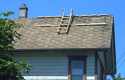
Collector Mounting & Installation
 Harder than every other aspect
of the work
specifically
for my installation was getting the collectors onto my roof. After a
couple more work sessions and trips to the hardware store, the mounting
boards were finally ready to go, and in an exhausting three hour
session on the 8th my renter and I bolted them onto the roof. The
upper board had four eye bolts spaced along it for clipping the lanyard
of the body harness to, so once it was attached, things got safer. The
ladder I made to hook over the roof ridge was, as I expected,
indispensable for installing the lower board, as were a couple of 'jig'
boards to hold it up and set the spacing between the upper and lower
mounts.
Harder than every other aspect
of the work
specifically
for my installation was getting the collectors onto my roof. After a
couple more work sessions and trips to the hardware store, the mounting
boards were finally ready to go, and in an exhausting three hour
session on the 8th my renter and I bolted them onto the roof. The
upper board had four eye bolts spaced along it for clipping the lanyard
of the body harness to, so once it was attached, things got safer. The
ladder I made to hook over the roof ridge was, as I expected,
indispensable for installing the lower board, as were a couple of 'jig'
boards to hold it up and set the spacing between the upper and lower
mounts.
The next day, we set up a 30 foot ladder and collected the
socket wrench and a small board from a gutter, and cleaned the
full-to-the-brim and more gutters. While up there, I got an idea for
winching up the collectors.
 Short of rope,
I went back on the roof on the
10th and
threw 1/2 of a 100' extension cord down each side. Then I set up the
2000# winch on the ground on the north side and tied the cord to the
winch cable. At the peak of the roof the mounting board would prevent
digging into the shingles. I tied the first collector to the end on the
south side of the house. We set up a 32' ladder there (it reached the
eves, but was rather steep). My renter did nearly all the climbing and
got all the shingle burns that day. We got one collector up.
Short of rope,
I went back on the roof on the
10th and
threw 1/2 of a 100' extension cord down each side. Then I set up the
2000# winch on the ground on the north side and tied the cord to the
winch cable. At the peak of the roof the mounting board would prevent
digging into the shingles. I tied the first collector to the end on the
south side of the house. We set up a 32' ladder there (it reached the
eves, but was rather steep). My renter did nearly all the climbing and
got all the shingle burns that day. We got one collector up.
The next day the extension cord "rope" jammed somewhere
and the power of the winch broke it. The second collector fell from the
eaves to the lawn and broke - a zillion little bits of safety glass,
mostly still stuck to the collector surface as a single sheet. There
was a collector with a badly bent up
frame at HES, and I got it for a good discount. I also bought a thick
rope. We got the collector up, but at one point the rope jammed and I
think if it had been the extension cord we'd have lost that one too.
Unfortunately it didn't match the first collector, so instead of two
pairs, there are three types. Beggars can't be choosers.
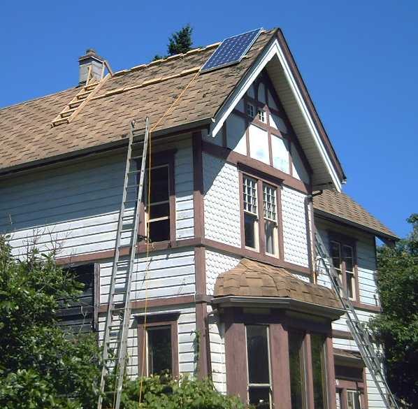
The next day we were getting
closer to the
point we climb
to the roof from. At the same time, the fig tree was in the way of
winching up the last two (slightly smaller) collectors, and we
decided we could manhandle them up. We got them into place.
In spite of all the prep, the top board didn't sit flat
and so various things didn't fit as intended and had to be reworked on
the spot, on
the roof. One corner of one collector wouldn't quite latch properly
into
place... I think it'll hold in a gale. We couldn't get at it.
Now I could only wish the collectors' glass surfaces were
covered with my titanium dioxide nanocrystalline borosilicate glass
"lenses" to effectively gather 25-40% more sunlight over the course of
each day. The four collectors would be the equivalent of five to almost
six, gathering more energy earlier in the morning, and especially in
the later afternoon before the batteries have to take over for the
night and house lighting.
(I wonder if there's anything I can do with the broken
collector? It still puts out voltage - so far. Maybe sandwiching it
between two pieces of plexiglass (a clear one on top) can keep it from
disintegrating for a few years of some sort of productive use?)
Connections
I spent the afternoon of the 17th wiring up the
collectors, all four in parallel. Where the wire for each collector
came through the roof, I put in a 12 amp in-line AGC fuse holder at the
attic
ceiling. It must be remembered that solar panels generate electricity -
they're live circuits all day and can't be turned off (except by
working at night). And as it turned out, I had to pull the fuses out
not only to do the wiring.
The common connection seemed to be putting out the
voltage of the two slightly lower voltage units, and I surmised that
the two
higher voltage ones must be feeding power into the lower. I removed the
fuses from the higher voltage ones until I could check it out. Someone
confirmed the next day that they should all be tied together with
blocking diodes. My first, smaller, collector had two diodes, built in
in the box underneath. It was only on examining the 'sealed' box on the
broken collector I realized these large panels didn't have any. Thus I
spent the evening of the 18th making an aluminum box and mounting two
30 amp bridge rectifiers with some attached wires inside. On the 19th I
went back in the ucky, fiberglass-dusty attic one more time, ripped out
the wiring box, and put in the new box with diode bridges, using two
diodes from each bridge.
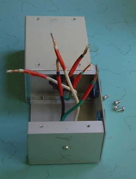
Solar panel junction box with 30 amp diode bridges
Homemade Thermoelectric Fridge & Freezer
I had been lamenting the lack of suitable low voltage DC
appliances at affordable prices. In particular, fridge and freezer are
indispensable items that always have to be on, and consume considerable
energy. It's a big issue for
off-grid and solar living. Plus I've never cared for the
compressor noise of fridges - they make most every kitchen an
unpleasant living
space IMHO, and
the idea of adding a big inverter with a noisy
fan seems much worse.
I tried out the 750 watt inverter with a 12V, 30 AH NiMH D
cells battery, on my countertop apartment size refrigerator. (A 400
watt inverter tripped off on overload
just as the fridge came on.) It
worked, drawing just 12 amps from the batteries and using 120
AC watts. But in addition to the continual howl of the fan, the
converter continued
to draw .6 amps
when the fridge was off. Furthermore, if power is interrupted, the
inverter turns itself off until manually reset - not the best for
running a
fridge or freezer!
It was a setup that could keep some food cold in a pinch,
but I
could hardly see it as a satisfactory long term solution. Low voltage
DC fridges cost a fortune. Sunfrost was recommended, but where a 120VAC
fridge could be had for 300$, I found they were listed at 3000.
I had heard of thermoelectric cooling, but I had been
advised that it
was inefficient and good for not much more than camping cold drink
coolers.
Now I found some low cost fridges that were small, indeed intended for
campers
or boats. One 'Koolatron' unit said it could be fridge or freezer. It
was unique in
using refrigerant pipes on the outside, heated to gas by the outside of
the peltier element and cooled by recondensation. This kept the outside
element cooler for a similarly cooler inside temperature. The units
were also only
around 50 to 75 watts, and not too costly. I could buy one,
or
perhaps two. But they wouldn't hold much food.
Then I had the thought that one could buy the elements
alone, and make a
larger 24 volt fridge of 80 to 150 watts or so. Tripling the size only
doubles the surface area and power requirements, and I started
to think that a decent size fridge might not use more power than a
compressor based fridge after all -- if it was really well
insulated.
Regardless of actual efficiency, the Peltier module fridge seemed like
the only practical fridge one could make at home. I decided to
consider making a project of it - hopefully a short
duration one compared to my other long drawn out works - started
looking into it, and was
quickly immersed in it. Perhaps there was potential for salable
products - certainly I wanted one myself. (Project writeup below under
its own title.)
Voltage
If I had a completely free choice, I'd probably go with
about 30 to
36 volts DC. It's low enough to be virtually safe from electrocution
hazard, but currents are only 1/3 of those for 12 volt systems, saving
substantial copper to wire a house.
But large solar
collectors are made for 24 volts - actually putting out about 35 open
circuit and 30 at maximum power, so maybe 24 isn't an unreasonable
limit, indicating a nominal
battery voltage of under about 26 volts. Collectors for 12 volt systems
can be had (at least here)
only at a very stiff premium. I don't understand why this should be,
but unless I get back to the DSSC solar cell project, I'm stuck with it
- along with everybody else.
There's no simple way to get to either 36 volts or 12 volts,
where either would be trivial with 12V collectors.
24 volts should be
a good level to use,
but 12 volt loads are common for automotive, boat and RV use, and other
voltage appliances including 24 are relatively hard to find. 12 volt
LED lighting and 12 volt fridges and coolers are examples. 120 VAC
inverters too are mostly made for 12 VDC input in spite of the high
currents
often necessary. (Eg, 1500W means over 125 amps at 12 V.)
So a 12V distribution is, at least, simple, whereas both
24 and 36
volts are hard to find appliances for.
Perhaps the simplest way to get from 24 volt collectors to
12V is to
have +12, ground, and -12, with two sets of batteries in series. But if
all the appliances are 12 volts, what good is having 24 at all? It just
makes
balancing the two sets of batteries necessary, pretty much manually.
Surely it's better to have all the batteries in parallel and equally
sharing the load. Having just one voltage is a good simplification.
24 V & Other Voltages - NiMH - Cordless Mower - Plastic 12V NiMH
Enclosures
On the 22nd a friend brought me a cordless lawnmower whose
lead-acid batteries (tho one was less than a year old) evidently
weren't holding
a lot of charge. It was 24 volts. Also handicapped scooters are usually
24 volts. These might be charged directly from a 24 volt system. Hmm...
there's probably enough call for a dual voltage system after all. At
least for a 24V solar charging circuit even if the house voltage is 12.
And 36 volts if I want to charge an electric car from it - triple
voltage. Plus of course, there's the inverters to get 120V for power
tools, small kitchen appliances, and other, hopefully temporary use,
loads.
I replaced the 20 AH lead-acids with 40 NiMH D cells to
attain
the same ratings, a 400$ job (~300$ for the actual cells) in trade for
the work he had done and would do to renovate my web site, even tho in
a year and a half we didn't have it up yet. At 6.6Kg they were less
than 1/2 the weight (of 14Kg), and they would outperform the PbPb's -
and last for many years. I did a soldered together pack, because the
"battery stick" pipes made a battery that wouldn't quite fit in the box.
Charging still needs to be set up. I have a feeling the
original charger as is would fry the NiMHs.
It occurs to me as I finish this newsletter up that I can
probably make 10 D cell (2 cells x 5 rows) plastic battery enclosures
with the 3D printer. That should pretty much solve all the problems and
make making battery packs a snap.
DC to DC Converters
I began to realize I should be either buying or making
converters for solar power for both the 12 VDC house and for 36 VDC
cars. (Maybe solar panel makers get kickbacks from DC-DC converter
makers to make the panels 24 volts? Conspiracy is a much copied and
highly successful business model. More money can be squeezed out of
customers to pay for things they shouldn't want or need. Well, that's
probably not it in this case.)
But a single 24 to 13.8 V converter/battery charge
controller on the collectors could make the entire system 12V.
(delivering up
to 13.8 with sunlight and charged batteries.)
I looked on the HesHomeEnergy.com website and found there
was something available closer to what I wanted than I expected.
Specifically, there were Schneider Electric charge controllers for 24
volt collectors for 200-300$ that had 'adjustable' settings for NiCd
(same voltage as NiMH), low voltage cutoff, and a dump load ("eg, an
electric water heater") to make use of any excess power while the sun
was shining. Apparently some of my planned "DC Grid Tie" features are
already commercial. That could simplify my parts. But did the NiCd
charger work the way I want? I've already seen that my 13.8 V "constant
float voltage" charging does a better job than commercial chargers that
charge to 14.2 and then shut off. The cells seem to have more charge,
and they probably will last
longer. And what if I get my MnMn
batteries going and the
'adjustable' charge voltage doesn't quite fit?
What it boils down
to is that I don't trust the present generation of commercial
solar-electronic products. The commercial charge controller I got last
year should have worked great in theory with a diode to drop its 14.4
volts to 13.8. In fact, it had to be tricked to put out anything with
the diode there, and then it put out a high pulsed
voltage averaging 14.4 that would soon have fried my NiMH
cells. I put a
filter capacitor on it to smooth it out, and then the controller itself
soon quit working. Wasting money on crap doesn't help the cause! Then
there's the inverter I got that went up in smoke when momentarily
overloaded instead of shutting
off. It was still within its
supposed momentary overload rating. (I have had better results with
other inverters.)
I tentatively decided to make a buck converter. The
formulae for determining the component values looked complicated.
Then someone loaned me a commercial 18-48V to 14V DC to DC
converter. It used a
control circuit I'd seen on the web with two 555 timers. I was however
impressed with
the number of components and the physical size and heavy wires of the
inductor, tho it
was
only around 15 uH. I can do it with fewer power components, and
otherwise copy the salient features such as the general size and weight
of the coil. But this one did
unpleasant things if the solar panel wasn't putting out enough power.
The specs sounded great, but in practice it just wasn't made for use
with solar panels
in unattended operation - just the reason I want to design my own to be
sure it behaves optimally in all conditions.
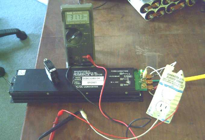
31.7 volts from solar collectors through individual fuses, isolation
diodes, yellow wire from attic,
and switch (later replaced by circuit breaker switch [sitting on top]
and ATO fuse)
into Zahn 18-48 V DC to DC converter, putting out 14.1 volts (direct)
or 13.8 volts to charge NiMH batteries (through Schottky diode to
prevent discharging through converter).
80 amp unit should handle up to 30 amps from collectors, delivering
about 60 amps at the lower voltage.
Key features of what I want:
* An enclosed wiring chassis.
* Terminal strips with fuses to connect several solar panels.
* An input circuit breaker/power switch.
* If Vin gets much above MPPt, current goes to the dump load (Hot Water
Preheat Tank) output to bring it down.
* While Vin is at or above MPPt, battery charge Vout is a constant, eg
13.8 volts. (Adjustable ~
11-16V.)
* If Vin drops below MPPt, Vout is reduced to keep it up. Thus Vout
becomes a constant current source putting out as much as it's able to.
* Additionally, if Iout is above its (broadly adjustable) max setpoint,
Vout is reduced to keep it within limits.
* If Vin falls below the minimum required for proper operation, the
output is turned off. There should be a considerable voltage hysteresis
to
help prevent on-off-on-off looping.
* If the converter output is turned off, it draws no current back from
the load. (ie
from the batteries.)
The batteries then must supply current to the house. If the voltage is
a constant 12 volts, the LED lighting doesn't need fancy power
supplies, just a current limiting resistor. Furthermore, if a DC to DC
converter feeds the house, the batteries could be much higher than 12
volts. But a low dropout linear regulator to go from 13.8 volts to 12
might be just fine, too.
Then again, feeding the house straight from the batteries
yields maximum efficiency, and that's probably what I'll do.
Superinsulated Thermoelectric Fridge & Freezer
[This is really long. I was going to do a major hacking and slashing,
but it's the 3rd of August and I want to get this newsletter out, so
you get it as is, with a few pictures added.]
Cooling(?) to the idea of making a peltier effect
thermoelectric fridge on July 2nd, I
realized design options were more flexible than for a
compressor fridge. Instead of a traditional upright shape, one could
make a shallow chest style with a lightweight lid. That wouldn't lose
as much cold when the
door (lid) was opened, and the food would be generally easier to find
and pull out. By
the 5th my head was spinning with ideas for shapes, insulations,
multi sectional lids and internal dividers, pullout cold drawers, and
other design ideas.
Design ideas
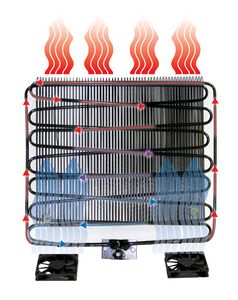
A substantial aluminum outer heat sink could spread the
heat from the warm end of the modules, and an inner one would spread
the cold around inside. I thought these should be effective enough to
be
efficient while eliminating the need for a fan.
The outside walls that weren't aluminum might be a light
wood, which would be good extra insulation, or plywood, perhaps with a
melamine 'countertop' lid. The inside surfaces could
be made from rigid plastic sheets of some sort, or PP-epoxy. Custom
smaller inside plastic pieces
might be made by 3D printer. The whole chest could be made heavily
insulated with good stuff, to minimize running time and power
requirements. Perhaps 2, 3 or even 4" of high density styrofoam. (It
would be a bonus to use styrofoam packaging material being thrown out,
but that
rarely has any straight sides. Unless some process were developed, it
would be a nuisance trying to fit it.)
It might be built as a fat table, or as a 'counter' with
drawers underneath. A
freezer could be pretty much the same with a lower temperature setting.
Perhaps they could be dual purpose units - as indeed one of the small
commercial ones was.
Control
A temperature probe coupled
to an LM339 could turn on a
low side MOSFET to supply power when the unit was above temperature.
More exact temperature control could be achieved than with a compressor
fridge. A
light might be superfluous, or it could be an LED light in the lid...
perhaps with a mercury/gravity switch to activate it when the lid was
tilted (open).
Peltier Cooling Modules
The same night I thought of the idea, I went to
Digikey.com and found "Peltier Modules" of various voltages, currents
and wattages. From one manufacturer they were all under 20$. They all
seemed proportional: the more
power, the more cooling. These were probably what the fridges used. I
ordered two 12 volt, 6 amp modules (~72 watts) each capable of
delivering about 40 watts of cooling at Victoria BC room temperature
(18ºC) & refrigerator temperature (2ºC).
And I started thinking about how they'd work and how to
set things up. My intent was to
put them in series for 24 volt operation, or it might be 12/24 with a
plug/jumper or two. That would give about twice the cooling power of
the
little camper/boat fridges... and I'd only spent 50$. If it's excess
cooling I could use it for a freezer and get a couple of smaller ones
for
a fridge, but I suspected it'd take substantial insulation just to get
it refrigerating well.
The power and controls should be pretty straightforward,
so the main concern is to make a nice box that keeps the cold in, and
that one will feel good about putting one's food in. I'd be proud to
have the only homemade fridge and freezer on the block! And they'd
probably save 15-20 $/month of electricity over my present units when
it's sunny; maybe 1/2 that when grid power is needed. It would be more
where electricity costs more than 10¢/KWH.
 On the third I thought about the refrigerant
"heat pipes"
of one
commercial peltier fridge/freezer. I probably couldn't do that... but
what
about
attaching the
outside heatsink to a main cold water pipe coming into the house to
keep it cooler, or even 'cold' in winter? That would do even more to
improve the efficiency, for free! That would improve efficiency and
reduce electricity consumption - especially in winter for a fridge!
On the third I thought about the refrigerant
"heat pipes"
of one
commercial peltier fridge/freezer. I probably couldn't do that... but
what
about
attaching the
outside heatsink to a main cold water pipe coming into the house to
keep it cooler, or even 'cold' in winter? That would do even more to
improve the efficiency, for free! That would improve efficiency and
reduce electricity consumption - especially in winter for a fridge!
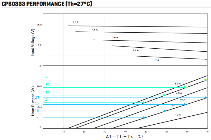
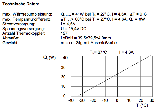
Performance data for the peltier modules
From the graphs, assuming about 13.8 (27.6) volts from the
batteries and 75 watts in, efficiency is double for a fridge in winter
with cold water cooling than for a freezer in summer without it:
0º difference (winter cold water - fridge): ~49 W cooling
power
15º (typical for fridge in air; or freezer with winter cold
water): ~38 W
30º (freezer, summer air): ~27 W
And that's for typical Victoria weather - efficiency will be
worse where
it's hot. 75 watts in yielding 49 watts out is about 65% efficiency. I
believe this rivals compressor fridges, but I seem unable to find any
definite figures. 25 watts out for 75 in is only 33%. This means double
the power for the same cooling effect, and much more than double the
power overall because a greater temperature difference must be
maintained.
The upshot is that
if the heatsink can be coupled to a cold copper water pipe, it seems to
be worth doing so, and indeed it looks like at good way to get at least
acceptable efficiency from a peltier module freezer.
I was also said that the efficiency drops as the power
rises.
When the peltier
modules arrived, I hooked one up to a
power supply. In
about one second one face was quite cold and the other was almost too
hot to touch. A passive heatsink for this was going to need massive
quantities
of aluminum, starting with big cubes of it to get the heat out past the
insulation. If cold water was used, it would have to be flowing.
Peltier Elements in Series (Thermally)
Breaking the narrative sequence, on the 25th, I got an
idea for possibly making the units more efficient. The smaller the
temperature difference between the hot and cold sides, the more cooling
watts they produce per watt of power consumed. (See my yellow lines on
the graph.) For a 30º difference, it pumps only 1/2 as much heat
per amp as for 0º. If instead two peltier units were
placed thermally in series, they'd only be pumping across 15º
each. Then they'd each make 1.5 times as much cooling. They'd use
almost the same amount of power, each, so 2x power, but 3.0x cooling.
With 3 peltiers across 30º, 10º each, efficiency improvement
would be 39/24 = 1.625. The total power could be brought back down by
buying lower current elements drawing 1/2 or 1/3 the amps.
For a 20º temperature drop it's less amazing, but
still significant, two 1/2 current peltiers being 22% improved over
one. A secondary effect would be doubling the thickness and hence the
insulation value at and around the peltier module.
Obvious questions: Why wasn't this being done? Was it
being done but nobody's mentioned it? So I looked for references. As it
seemed when I tried one out with my fingers, the hot side got hotter
than the cold side got cold. This is because it has also to dissipate
the heat of the electricity being used as well as that transferred from
the cold side. This is more
extra watts to cool than the amount saved. (That also explains the
cooler's outside heat sink and fan being bigger than the inside one.)
Peltier Element Heat Pump/Electric Heater
An interesting aspect to this is that peltier modules
could be used as electric heaters, and if the cool side went to a
fridge or outside, they'd make more heat in the house than the amount
of electricity used. Ten 60 watt peltiers, suitably arranged, could
make a heater/heat pump delivering about 850 to 1000 watts of heat into
the house while using only 600 watts of electricity.
That certainly isn't as good as a compressor based heat
pump, but it's a fair improvement over a plain electric heater.
Considering the cost of electricity, the peltier elements might pay for
themselves in one heating season. The heater could be mounted in a
double hung window, or a hole could be made in a wall for some sort of
heat exchange pipes. Since it's a small heater, a hole for a "ground
source heat pump" pipe might be dug in the ground with a shovel. All
depending on climate of course. Here we're typically heating by
10-15ºc much of the time.
Experimenting anyway...
On the 31st, frustration with trying to get enough cooling
led me to try the two-stage thermal series arrangement anyway. I
decided to have the outer peltier running at full power, and the inner
one at maybe 1/4 power (with series resistors), so its resistive heat
wouldn't overpower the cooling of the outer unit. The cold side should
thus get colder - if it had enough power to cool the space it was in.
This time, in order to sense the temperature of the
aluminum block between the two peltiers, I took everything apart, and
held the warm side fan against the heat sink. Direct measurements -
minutes instead of hours to see how cold or warm things would get.
I had already found that the outer heat sink was getting
quite warm, as high as 40ºc. That meant the peltier itself wasn't
trying to cool from (eg) 22º, but from (eg) 35º. So it was
actually cooling by 26º to cool from 22º down to 9, rather
than just the 13º. Now things started to make sense. It cooled
quickly at first because the outer heatsink was still cool. Then that
started getting warm, making the job of the peltier harder. By the time
it hit 26º drop, it was operating in a less efficient range
altogether.
It was about 23º in the room. Neither the inner
heatsink nor the fan was attached to the inner, coldest block of
aluminum. The unit settled down to the following readings:
volts outer middle inner
heatsink
block block
11
34º
17º 0º
12
35
19 0
13 35
19
0
This seemed more satisfying: at last I was seeing
fridge-like temperatures, if only on an aluminum cube. It was, however,
a bit disconcerting that 3/4 of the energy was going to provide a
starting point only a little below room temperature for the inner
element. It shows how much would be gained with cold tap water - or
even strongly circulating room temperature water.
The fan sped up with voltage, so the outer heatsink didn't
get much warmer with increasing voltage and power. The three 5 watt,
1.5 ohms resistors (=4.5Ω) limiting power to the inner element got
quite hot (but they were away from the cooling unit). Current to the
inner peltier was about 1.5 amps out of about 5.5 total. It was using
maybe 6 watts.
Obviously the original unit isn't good enough because the
warm side heats up too much. If that didn't happen, it would get down
to freezing. Instead of using extra power for a two stage cooler, a
self-circulating water system to keep the warm side of the peltier
element cool might be optimum. Aluminum is attractive, but copper can
be soldered, and is an even better heat conductor. And there's lots of
copper plumbing fittings and radiators available. If the warm side of
the single peltier could be kept down even to 30º instead of 35,
the cooling limit would be about 4º - within acceptable fridge
range - instead of 9.
A water cooling system plus a two stage peltier should
give sufficient temperature drop for warmer climates, or to make a
freezer. But as I write this it's the end of the of the month and I
have yet to try out the two-stage unit in a cooler or fridge. The
second peltier uses only around 25% additional power, and I can play
around with how much power gives the best results. It might work great
as-is with only a slight power penalty - if the second peltier, running
at 1/4 power, delivers enough cooling watts for the space. If not,
total power will have to rise, maybe to 100 or more watts.
Peltiers in Series (Electrically) - sort of
On looking at the graphs again, I noticed that the watts
of cooling apparently depended on the current input, not the power
input. 4.8 amps with a 20º drop needed 12 volts, which is 57.6
watts. 2.4 amps with a 20º drop needed a little over 6 volts -
only about 15 watts. That's 1/4 as much power, but giving 1/2 as many
watts of cooling, or twice the cooling per watt of electricity. Two
parallel pairs in series would give twice the cooling for the same
power input. Was this for real, or was there something non-obvious that
would negate this supposed effect? Why wouldn't the electric cooler and
fridge makers make use of this? How could such a thing possibly be
overlooked? Were they simply all too cheap to put in two peltier
elements instead of one, in order to cut the power almost in half?
If the theory was correct, twice the cooling could be had
for 2/3 the power with two banks of three peltiers. The ratios are
however temperature dependent, and the peltiers aren't cheap when you
start talking about a half dozen or more. At some point, peltiers
thermally in series might also be employable to advantage, especially
in a freezer.
I decided to try the 2 identical peltiers I had,
physically in parallel, electrically in series. That would, according
to my reading of the charts, be half the electrical power but probably
about the same cooling power at 20º drop. If this worked, then two
more peltiers should give twice the cooling power with the same amount
of electricity.
Reality cut in when I tried it. It seemed this arrangement
provided about 1/2 as much cooling for 1/2 the power, as the cooler
dropped by 7 degrees instead of 13. That figures.
Commercial Thermoelectric Cooler
Meanwhile back on the third, I had coffee with a friend,
and he told me
there were thermoelectric coolers at Canadian Tire. I thought I might
as well look. There were 35 litre ones for 130$ and a 45 litre one with
wheels, almost the size of the small fridge I'd looked at on the web,
for 160$. These were the height for my shallow tray idea, albeit 1/4
the capacity overall and not as well insulated. I bought the
large one. It draws 5 amps (x12v = 60 watts), is supposed to cool by
"up to 20ºc", and has no
thermostatic control. Would this replace making my own?
I tried it out. It cooled glacially slowly to about
4ºc. The 120V
power
adapter drew .55 A. (x120v = 66w) and got very hot. The regular
countertop fridge drew
1.2 A (x120v = 144 V-A) but it has twice the capacity, and it only runs
maybe 1/4 of the time. (And since it's a motor, the V-A may be higher
than the actual watts.)
As the inside got
cooler - very gradually - the outside surfaces also started to seem
cool. Was it
just my imagination, or was this
thing not very well insulated?
Maybe making the larger but better insulated and thermostatically
controlled fridge was still a good idea - but using this pre-made
peltier cooling unit.
The cooler uses 60 watts. If it ran full time, it would
use 44 KWH per month. If I'm not being too optimistic, hopefully it
would run 1/2 the time and use 22... or even less. My present fridge
says it uses 75. Newer more energy efficient ones claim as little as 35.
So even if it does it by super insulation and smaller
shallow chest layout, I think a peltier fridge might be energy
competitive (or even save energy) rather than, as is commonly said, be
too inefficient to consider for anything bigger than a cooler.
On the 23rd I took the unit apart to have a look. The
outer fan pulled air though a duct shrouding a considerable heatsink
with about 3/8" thick alumimum where it contacted the peltier element.
The inner fan blew air through a lesser heatsink, which, being just
used, still had condensation where the element was beneath. I was
wondering if that one should have had more fins to blow the cool away
faster. It was plain that my originally envisioned arrangements for the
loose peltier elements I bought would have been quite inadequate -
except maybe for the idea of having cooling water. Even that would have
needed to be flowing water, or to circulate well. The beauty of
I tried to remove the heatsinks, but even with the screw
out they wouldn't budge. I suspect they were glued to the peltier
element. I really wanted to see in there, but I considered that the
peltier element itself might rip apart before the glue came loose, so I
quit while I was ahead.
Later it developed that this cooling unit would only cool
by 13 or 14ºc, regardless of what it was mounted in. I took it
apart again, this time completely. I couldn't fault the design or
construction. There was a temperature sensor in the cold side. I pulled
it out of its hole and simply set it in the warm side so it wouldn't
decide the unit was too cool, and put it back together with just a few
screws. That didn't seem to help. (It probably simply shuts the unit
off, at a temperature it never reaches.)
But I wrote down the number off the peltier, and now
looked it up. It didn't seem as good as the ones I'd bought from
Digikey. With null temperature difference, it delivered only 41 watts
of cooling for 71 watts of electricity, where the others put out about
48 watts for about 65 watts in. The apparently improved specs
looked like a good reason to replace the one in the cooler. However,
there's theory and reality, and the new element seemed to work about
the same.
Form of the Fridge
To make a fridge using
the
pre-made
module of this cooler with its fans and all as the cooling unit
started to look more promising than my passive heatsink design.
I
could also copy a couple of the cooler's ideas: first, make the lid in
2 or 3 separate sections. And to further refine
that, put vertical dividers at the joins to limit air into the closed
section(s) when one is open. Second, make them open right to vertical
so they'll stay open (better than a prop), and lightweight so they
don't slam shut. That's very different from my old freezer that tries
to eat you when you stick your head in and slams shut hard if your
hands are too full to lower it gently.
Finally, a section needs to be 12" tall for tall
containers, but the whole thing doesn't need to be so tall. If that was
a small section with only 3" insulation top and bottom, the next
section could be 10" with 4" insulation. The far end could either be
just 8" tall with 6" of insulation, or it could be a 4" tall pull-out
tray with a 6" space underneath.
A further sub option to this, if it could be done without
wrecking the insulating value or the seal, would be a 6" pull-out
drawer under the 4" section... or two drawers. I rather like that:
instead of "opening the fridge", one simply pulls open a "cold drawer"
to access small items. That might lose still less heat, as the back and
sides of the drawer could still pretty much close off the remainder of
the fridge
from the open drawer. Lid sections, however, would be simpler than a
drawer or drawers, any any air leak or insulation gaps around a drawer
would cause serious cold loss.
Insulation
So if the critical thing is insulation... how good was the
insulation on the cooler? The main body had no apparent way of opening,
but the lid pieces screwed together. I took the large side (with no
equipment) off and took it apart. The insulation was a chunk of
'extruded' styrofoam molded to shape and inserted between the plastic
faces. Except for a couple of thin spots around the power adapter
holding compartment, it was mostly about 1.25" to 2" thick. There
wasn't much
to criticize. The only big improvement could be thicker or better
insulation, and maybe "aluminum foiling".
I worked out that for 18 x 36 x 12", the inner surface
wall area was 2.2 times that of the cooler. I had got the cooler down
to 4ºc. The insulation needed to be over twice as good to attain
the same temperature.
So then, what insulation would be
best? R8 (per inch) would do in 2" what R4 would need over 4" for. Some
materials seem to degrade a little with age. I found a
couple of tables, of which this seems typical:
| Urea Terpolymer Foam |
R- 4.48 |
|
| Rigid Fiberglass (>
4lb/ft3) |
4.00 |
|
| Expanded Polystyrene
(beadboard) |
4.00 |
(I have lots... but it's only R4!)
|
| Extruded Polystyrene |
5.00 |
(~75$)
|
| Polyurethane
(foamed-in-place - or sheets) |
5.5-6.8
5.5-7
|
Sheets: 500$
enuf pour foam mix: >100$
|
Polyisocyanurate
(foil-faced) [AKA "polyiso"]
|
5.6-7.20 |
>100 $ per 2" sheet?
|
Aerogel
|
10
|
VERY costly - hard to get
|
Vacuum
|
30-50
|
costly - hard to get
|
From one source: "Polyisocyanurate
is an evolution
of polyurethane. It is stronger and has greater thermal resistance. In
fact, PIR offers the highest R-value of any material per thickness."
A vacuum would obviously be
best. But foaming in place a bunch of thermos bottle liners wasn't
going to give a lot of insulation value. Aerogel (AKA "solidified
smoke", made by NASA) probably couldn't be had for any price, and I'm
sure must be daunting to make. I'm sure square sheets of 1" vacuum
cubes, or else commercial aerogel panels, ought to be developed for
refrigeration uses, but I'm not gonna touch those myself. (Hmm...
actually, 2 sheets of plexiglass with reinforcing rods every 1" could
be evacuated...) That leaves 'foams', in order of preference by 'R'
value.
Contrary to the chart and statement above, Wikipedia rates
"polyiso" below polyurethane, and part of it's value is ascribed to the
foil face... One could
'foil face' polystyrene, too - would that make it a 5.5 or a 6? - and
it's
readily available at building supply stores.
What about kiln bricks? They weren't on any list (they're
not even mentioned on Wikipedia!), but they're
almost as light as foam and insulate kilns at well over 2000ºF. I
finally
found info (on the very last click as I was giving up): http://www.traditionaloven.com/articles/81/insulating-fire-bricks
"In
refractory
air
is
the
best
insulation
and
this
is
why
insulating
firebricks
have
excellent
insulating
properties.
Their
body
is
made
of
tiny
air
spaces
similar to honeycomb effect."
- Thermal Conductivity 300°C : 0.2 W/m.°K
- Thermal Conductivity 750°C : 0.28 W/m.°K
- Thermal Conductivity 1000°C : 0.32 W/m.°K
Guessing around .15 at room
temp, that's maybe 3-4x higher than
extruded polystyrene, making kiln bricks under R2/inch. I thought
they'd be
better. No magic bullet there!
Then I decided to check out paper... and found a great
table. Wikipedia had a similar table (if not the same one):
http://www.engineeringtoolbox.com/thermal-conductivity-d_429.html
"Cotton wool insulation" beat polystyrene by a
very slight margin. On the other hand, that
wouldn't be much of a backing for thin plastic, and how could one
ensure a consistent result? And where would you get it? On the market
it's been replaced by polyester fiberfill AFAIK.
The inside insulation is the most critical. The outside
dimensions get larger and larger as the R value drops, using
disproportionately more material for each added inch of insulation, at
the same time making the volume to be cooled larger. For
an 18" x 36" interior space, with 2" of insulation the exterior
dimensions are 22" x 40". With 4" of insulation, that becomes 26" x
44". And you have to lift a larger, heavier lid and lean over farther
to get food. (And that lid will be above lightswitch height if the
fridge
sits on a countertop.)
If even the inside
1/2" could be R10/inch instead of R5/inch (making R5), the fridge could
shrink an
inch on all sides and still retain cold better. More practically, R6-7
(with polyurethane foam), 20-40% better, is probably worth some extra
money for the
innermost inch or so. I checked the web site of industrial plastics and
found sheets of polyurethane, but on the phone found that even a 4' x
4' x 12mm sheet was 166$.
That's just 0.44 ft^3, and not enough area to cover the whole
inside. It seemed prohibitive.
I thought about that then called back and asked about
expanding polyurethane foam pouring mixes. Enough for nearly 2 cubic
feet was 70$. The rep thought it was R7/inch.
That was much better. It would do over an inch all around the inside.
And presumably it could be done solid, with no cracks except
at openings. I decided that was, after all, the way to go for best
insulation effect, inside a 2" or thicker polystyrene (1/3 the price)
box
to add thickness around the outside. (If one poured the foam stuff at
reduced air pressure, or in a vacuum, I wonder if it would be even
airier and higher R value? Maybe it would be as light as aerogel?)
By the time I had the main pieces and materials I'd spent
390$. This was well beyond what I'd intended, but I think it's breaking
new ground - not in terms of absolute invention or discovery, but in
attempting to produce an all around more efficient 'shallow chest'
fridge design, and in the use of peltier elements and the very best
insulations for a low power, low voltage home fridge - one especially
suitable for solar homes.
Size of the Fridge & Requirements
For interior size 18"w x 36"L x 12"t and with 3"
insulation all around
(R17), it appeared there'd be 6 cubic feet of insulation surrounding
4.5 cubic feet of food capacity. In practice, I'd add more insulation
pieces where there were shorter containers, so it would be even less
space and more insulation. A more cubic shape could improve the ratio,
but utilization of the space would doubtless be poorer unless food was
stacked on food or multiple pullout shelves were employed. Or if the
lower
area was in pull-out "cold drawers" - but I decided to avoid that
complication.
How big were my other fridges and freezer? I did some
measuring and came up with these approximations of cubic feet:
Unit
|
CF actual
|
CF usable
|
Main fridge
|
14
|
10
|
Countertop Fridge
|
4
|
3
|
TE Cooler
|
1.5
|
1*
|
Freezer
|
21
|
10
|
Proposed TE Fridge
|
~4.3
|
4
|
* For camping, things usually get stacked on top of each other and the
entire space is well utilized. This is awkward for everyday use.
Another fridge-freezer I checked has 15 cubic feet of
fridge (18"w x 27"d x 54"t), and while I would have said it wasn't all
conveniently usable, the owners certainly have it stuffed to the gills
much of the time.
In giving typical "usable space" figures, I don't mean
holding that many cubic feet of food items, just that there are some
spaces typically almost entirely unoccupied, where it's hard to put
anything. Shelves
usually have unused space above the food, or else it's too hard to
access the food at the back. If the freezer was half filled, you'd
never find - or get at - the stuff at the bottom, so in practice a
shallow chest
holds as much food as a deep chest. (I've seen a deep freezer fully
packed. I'm sure some of the food underneath had been in there almost
since it
was purchased.)
It's evident that better utilization is a good bonus.
Still, the new TE/solar fridge wouldn't have 1/2 the usable space of
the big fridge. But it could fill the essential need for ongoing cold
food storage.
Igloo cutting
 Eskimos take a
big knife and cut snow blocks to
make an
igloo. On the 9th, I took a couple of them (and a tape measure and a
carpenter square) and cut styrofoam blocks to make the fridge. Another
inch of polyurethane foam goes inside the 2" thick pieces of
polystyrene. Obviously it's much more than just a camping cooler. True
it's substantially smaller than a 'regular' fridge, but food can be
more efficiently packed in. It takes up more floor area, but
surprisingly only 12% more, being a foot broader but 6" less front to
back - in fact, regular counter width if the lids are hinged or pinned
for flush mounting. There's room for some storage underneath, cupboards
above, and in a narrow passage, the absence of a door swinging out
could be an advantage.
Eskimos take a
big knife and cut snow blocks to
make an
igloo. On the 9th, I took a couple of them (and a tape measure and a
carpenter square) and cut styrofoam blocks to make the fridge. Another
inch of polyurethane foam goes inside the 2" thick pieces of
polystyrene. Obviously it's much more than just a camping cooler. True
it's substantially smaller than a 'regular' fridge, but food can be
more efficiently packed in. It takes up more floor area, but
surprisingly only 12% more, being a foot broader but 6" less front to
back - in fact, regular counter width if the lids are hinged or pinned
for flush mounting. There's room for some storage underneath, cupboards
above, and in a narrow passage, the absence of a door swinging out
could be an advantage.
I was wondering how to attach the foam pieces. I was
thinking epoxy - yuk. Hmm, how bout white wood glue? I glued two scraps
together with it. It worked well, tho it took a long time to dry.
Freezer Compartment
Strangely, it didn't immediately occur to me I could be
making a combined unit, a fridge with a freezer compartment. This may
be because my regular fridge has nothing more than an ice cube
compartment. Perhaps I should set aside 9 or 12" of the 36" width for
one. And if I added another inch of urethane foam inside, it'd have 4"
and be R23 or R24.
It would necessitate a dual temperature control: If the
freezer needed cooling, the peltier unit would come on. If the fridge
needed cooling, a louver could open, or a fan could come on, between
the freezer and fridge compartments. (Someone who once worked in
appliance repair says he's seen old fridges with a bimetallic strip
louvre between the freezer and the fridge parts.) This is assuming, of
course, that the cooler's 60W peltier cooler would be adequate to the
job. It's asking a lot of it.
Construction
I had to let it sit for a week or two while I did other
things, but on the 18th and 19th I glued the main body of foam together
and carved out a hole to fit on the cooling unit, in the right side. I
left the glue to dry overnight with the left side still separate. It
still wasn't dry, but I couldn't resist trying it out, empty, with just
the 2" of styrofoam, not very well sealed. With the inner inch missing
on all sides, it was 6.2 cubic feet. I tried it out - see Tests,
a
ways
below.
Doing the Urethane Foam Insulation - Hindsight: urethane spray
can foam is
about the same price as the two part liquid, easier to use, better...
and a great glue for the polystyrene sheet joins.
 Applying the
urethane anything like evenly proved impossible. It starts frothing in
about 20 seconds while you're mixing it, and after about 45 seconds
total, it won't flow any more. I tried spreading it around by hand, but
it mostly stuck to my latex or vinyl glove. As a means to fill the many
voids, I bought a spray can of expanding urethane foam and started
filling them with little squirts of it.
Applying the
urethane anything like evenly proved impossible. It starts frothing in
about 20 seconds while you're mixing it, and after about 45 seconds
total, it won't flow any more. I tried spreading it around by hand, but
it mostly stuck to my latex or vinyl glove. As a means to fill the many
voids, I bought a spray can of expanding urethane foam and started
filling them with little squirts of it.
I think the liquid foam would best be
poured, a bit per application, between two walls that are held stiffly
in
place, ie, as into a mold. Surely there are 1/4" sheets of polystyrene
that could be used to be smooth inside walls? It'd pretty much need a
plywood frame inside to hold them stiff for PU foaming.
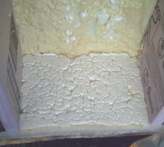
The "max expansion" spray urethane foam took far longer to
harden, and continued expanding and hardening a bit even overnight.
Every dip I filled became a bulge, and by the end I had sprayed the
whole first surface (the left end wall, bottom in image), and I put a
sheet of plywood and some
bricks on it to even it off. It ended up being 1.5" thick instead of
1", and probably an inch of that was from the spray can.
That being the case: the two part mix, supposedly enough
to do the whole interior over an inch thick, was 70$. The spray can did
almost 10% of it for under 7$. I think next time I might just go for
the spray cans and forget the two-part liquid mix.
The main concerns are: which has the higher R value?,
strength, and ease of use. The liquid mix definitely sets harder. No R
value is given for the spray cans, but they're far easier to use. Being
airier might mean higher R value. The liquid mix is almost problematic
it sets so fast.
Furthermore, one of the joins glued with wood glue popped
open. It had some stress and probably didn't dry undisturbed. I
re-glued it by spraying in a bit of the foam and clamping it for a few
hours. The spray foam proved to be the best glue, not only sticking the
pieces together well, but expanding to fill in any gaps in the join.
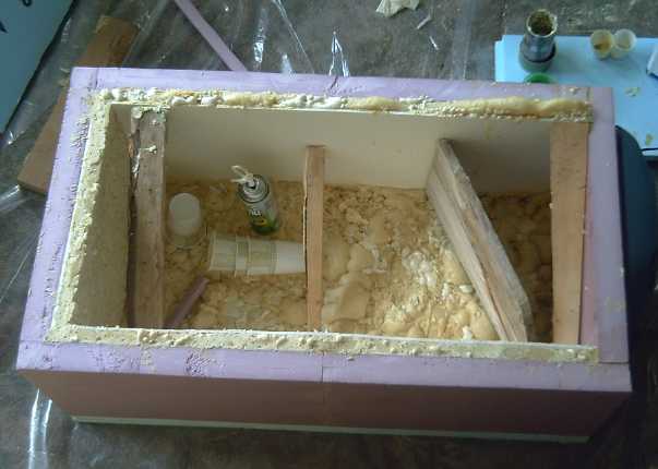 On the 22nd I
got "foamcore" at an art store -
thin
styrofoam with paper facing on both sides. I also got 'almond'
naugahyde (sort of matches my stove) for the outside front and sides,
more arborite, and a couple more cans of spray foam. The first one was
empty. I cut a piece of foamcore for the front inside, cut some pieces
of wood for props, and filled the 1" space in 6 or 7 passes with the
liquid mix. It was uneven and I finished up with the spray foam, which
ended up foaming up over the top in most places. At this point, half
the surfaces were foamed, but 2/3 of the mix was used up. I prefer the
spray cans more and more.
On the 22nd I
got "foamcore" at an art store -
thin
styrofoam with paper facing on both sides. I also got 'almond'
naugahyde (sort of matches my stove) for the outside front and sides,
more arborite, and a couple more cans of spray foam. The first one was
empty. I cut a piece of foamcore for the front inside, cut some pieces
of wood for props, and filled the 1" space in 6 or 7 passes with the
liquid mix. It was uneven and I finished up with the spray foam, which
ended up foaming up over the top in most places. At this point, half
the surfaces were foamed, but 2/3 of the mix was used up. I prefer the
spray cans more and more.
As I added insulation on the inside, it was obvious that
interior space was shrinking. And the top wasn't quite even - I found
myself wishing for a giant sanding block about 30" x 60" to square it
off with. The 18" x 16" ended up as about 17.5" x 34.75", and not
perfectly even. The floor looked like a mess of foam dog poop.
After doing each wall on separate days, on the 26th and
27th I did a floor of light coloured arborite after cutting down the
high spots and spraying foam in to fill in between them. On the second
half, I filled in with many small lumps of urethane foam cut from other
places. I still finished off the second can of urethane spray foam and
used the whole third one. The urethane foam was probably 1.5" thick and
better, for a total of 3.5+" of insulation.
semi-finished fridge box, open
and with lid with arborite, & naugahyde sides
An aluminum skin had been mentioned in connection with
polyisocyanurate foam insulation. I was ambivalent about trying to put
aluminum foil in somewhere. Then my friend who had mentioned the
coolers earlier now mentioned that the dollar store
had "space blankets": strong, lightweight, aluminized plastic. He
thought they'd be best covering the outside. They were cheap, and I
decided to put in three
layers of it, under the naugahyde. It would doubtless have helped in
the tests where the sun was shining on the unit.
The cooling tests weren't looking promising, but something
would surely work, so construction
proceeded apace. On the 30th I sewed up the naugahyde skin.
Bill of Materials
The materials cost added up surprisingly quickly. The
electric cooler, the urethane foam, and the extruded polystyrene were
the costly items.
* 1 - Peltier Cooling Module, eg from an electric camping cooler [are
there used ones?]
* 2 - sheets of extruded styrofoam, 24" x 96" x 2"
* 1 - 40" x 60" x 3/16" 'foamcore' sign board [art supply?]
*10 - 12 oz (g) spray cans (120 oz/g) of polyurethane foam "max
expansion"
* 1 - piece 2m x 1.4m 'naugahyde' for outer walls, floor
* 2 - pieces 24" x 48" arborite/formica/melamine "countertop": lid top,
floor
* 4 - space blankets
Tests
To make a long story short, the peltier cooler element,
advertised to be a 20º (all temperatures Celsius) temperature
drop, frustratingly only cooled by 13 or
14º no matter what, whether in my fridge or in the original
cooler. The cooler had got down to 4º when I first bought it, but
later only hit 8 or 9. Then I realized the difference was that at the
start of July when I bought and first tried the cooler, the temperature
was quite cool, maybe 18º, but that later it was more like summer,
22 or 23º. It didn't cool by 20º, which was about the minimum
requirement.
It turned out all this was because the outer heatsink got
up to about 35º. I was going to have to improve it or come up with
something better, and by month's end I did, getting frost on the cold
side of a two-stage peltier unit.
The many tests below show the frustration of putting in
more and more insulation yet getting no lower temperatures.
Current was 4.4 amps at 13.5 volts. That's 59.4W,
drawing 2.4 amps at 30.1 volts or 72 watts through the DC to DC
converter from the solar collector. 62W/72W=86% efficiency. (14% loss
on heavy loads is
why I don't want to regulate the house battery/solar supply at the
batteries. 59.6/62: The other 2.6 watts was lost as .6 volts drop in
the skinny alligator clip leads I hooked up the fridge with.) For
simplicity I used the cheap voltmeter temperature probe with unit
ºC figures. At 11:40 the increasing overcast caused the converter
to
crap out and I had to switch to wall power, which the temperature rose.
After I had two walls and the floor done with polyurethane
(23rd) I
ran a second test to see what the improvement would be. I set a clock
to 10:45 to get the same times. It was somewhat warmer and the sun
shone on the fridge.
The results from a number of tests show my frustration and
puzzlement that there was no improvement as more insulation was added,
before I realized it was the cooling element that just didn't have what
it takes.
On at
~10:45
|
ºC
20
|
ºC
22
|
ºC
22/24
|
ºC
22/19
|
ºC
21
|
ºC
23/21
|
ºC
21/17
|
10:55
|
15
|
18
|
21
|
|
18
|
19
|
13
|
11:00
|
14
|
16
|
20
|
16
|
17
|
18
|
12
|
11:10
|
13
|
14
|
18
|
15
|
15
|
18
|
11
|
11:15
|
12
|
|
17
|
14
|
14
|
|
|
11:20
|
|
13
|
17
|
|
|
17
|
|
11:25
|
11
|
13
|
16
|
13
|
14
|
|
10
|
11:30
|
|
12
|
15
|
|
13
|
16
|
|
11:40
|
10
|
12
(Room
23)
|
(I
went
out)
|
|
12
|
16
|
9->11
5' defrost
|
11:53
|
12
(Lost power)
|
11
|
|
12
|
12
|
|
10
|
12:00
|
11
|
11
|
|
|
11
|
|
10 stt 15'
defrost
|
12:10
|
10
|
10
|
12
|
11
|
11
|
|
12
|
12:15
|
|
|
11
|
11
|
10
|
14
|
13
|
12:30
|
9
|
10
|
11
|
|
9 barely
(Off)
|
|
10
|
12:31
12:32
12:36
|
|
|
|
|
10
11
12
|
|
|
| 12:40 |
|
|
10 |
|
|
|
|
12:42
12:49
~13:00
|
|
|
|
|
13
14
15
|
13
|
9
|
Off at
13:10
|
9
(Room
21)
|
went to lunch
|
9
|
|
still
15
|
|
|
13:11
13:13
13:15
13:18
13:21
13:24
13:30
|
10
11
12
13
14
15
16
|
|
(room 22º
throughout
this test.)
|
|
|
|
|
13:36
|
17 (end)
|
|
|
|
16-
17
|
|
|
13:55
|
|
|
8 (added
1" PS on top
|
|
|
|
|
Off at
14:05
|
|
8
(room
22)
|
|
|
|
|
|
14:07
14:09
14:13
14:17
14:22
|
|
9
10
11
12
13
|
|
|
|
|
|
14:29
|
|
14
|
7
|
|
|
|
|
14:36
|
|
15
|
|
|
|
|
|
14:46
|
|
16
|
7 (Off)
|
|
|
|
|
14:49
14:51
14:57
|
|
|
8
9
10
|
|
|
|
|
14:58
|
|
17 (end)
|
10
|
~15:15
~15:22
~15:30
~15:33
~15:45
~16:00
|
|
|
12
13
13
14
15
16
|
~16:20
|
|
|
17 (end)
|
1. It's easy to cool
the air the first few degrees. Then the heat stored in the walls (and
food, usually) starts radiating back in. As the unit gets colder, more
heat from outside seeps in, and the temperature difference that can be
attained is
proportional to the strength of the cooling unit and the value of the
insulation, counting air leaks and all.
As the day wore on, the overcast thickened, and the
voltage from the collectors drooped to about 26.x volts. Turning the DC
to DC converter off and back on to check current, it wouldn't run
again and instead made strange noises. I had to start the
fridge going again with a power adapter. (The DC to DC converter would
still run a 1 amp LED light, with the collector voltage at 32.6.)
The fridge didn't get cold enough, and once the cooling
was off, it rapidly got warmer again. It could probably be better
sealed. More, higher R value insulation on the inside would definitely
help. How much more would it need?
If it turns
out to need 2" instead of 1" (total 4", about R23), it'll just be
smaller inside than I'd planned. And the more the insulation, the less
often it'll need to run and the less energy it'll use.
2. The results from the half PU foamed fridge seemed disappointing.
With the warmer room temperature they actually looked worse, but in
terms
of degrees cooled they were slightly better. Although I used the same
skinny wiring, voltage was 13.6 and it drew 4.6 amps. The sun being out
(later, light overcast), the
solar system and DC to DC converter had power to spare, and I charged
some NiMH batteries at the same time.
At about 12:00 FBT (Foney bogus time) I noticed there was
a bit of an air gap
under the lid near a corner. I stuck in a folded piece of paper (as I
had done on the first test from the start), and then went around
sticking more bits in anywhere they'd go. This probably helped a
little, but not dramatically.
After the cooling was turned off, the unit definitely held
temperatures a little cooler for somewhat longer, in spite of a
slightly higher room temperature.
At this point it certainly didn't look like the whole unit
could make it down below zero to use as a freezer, or that as a fridge
it would shut off very often and use less electricity. If I added a
second peltier module and it ran all the time, it just might be a
freezer, but it would use as much energy as my big fridge. Of course, a
small compartment should make it down below zero, at slight cost to
efficiency.
3. After doing the other two sides, all was foamed with PU except the
lid. Altho the room was 22º, sun through the window
had heated the inside to 24º when I started the test, so it had
extra heat to overcome. After the first 1/2 hour the sun had pretty
much moved off it, but still the unit seemed to cool much more slowly.
That seemed puzzling. One factor was that the tops weren't very flat or
even, so some extra air might have been leaking in. But stuffing folded
papers in the cracks didn't seem to help. Did the "foamcore" or the PU
have far more thermal inertia than the PS? If that was the case, it
should warm up more slowly, too.
At 13:10 FBT, exhaust air seemed quite warm. The
temperature having dropped only to 9, I realized I had connected with
heavy wires instead of the previous light ones that were losing 1/2 a
volt. The unit's cord would be getting the full 14.1 volts. I
reconnected with skinny wires and through a diode, getting 4.3A at
13.2V. Perhaps it worked better with a lower voltage? It didn't make
any noticable difference.
It didn't look like it would get below 8º. I added a
1" thick piece of polystyrene on top of the 2" lid. It finally dropped
to 7, but not for 1/2 an hour.
But after I turned it off, it took over twice as long for
the temperature to rise as the previous time. The insulation was surely
much better, yet it didn't get much colder. It seemed more like the
cooler module that simply didn't want to get colder, rather than the
fridge. Even its original small cooler barely got under 5º.
By this time, I was starting to regret that I hadn't
started the first test right on an hour.
4. I turned the unit back on (the same day, 25th) and casually ran my
hand around the cooling unit. It felt cool there. I had planned on
adding some more shrouding around the unit but thought it was a minor
point. Could it be I was losing my cool? (happens easily when I get
frustrated.) So I made a sort of a shroud thing and turned it on for
another test. (2" lid) This time it started at 19º since I'd
already had it running. But it didn't seem to cool even as fast, so I
quit the test.
5. The same evening I put a short wall between the inner air intake and
outlet to force the cool air to flow farther into the fridge before
going back through the cooler, in case the cooler was working harder by
cooling extra in its own vicinity. All the insulation had made the
cooling air rather recessed.
This test was done after dark. It was disheartening how
fast about 4.5 amps seemed to drain a 30 AH battery of 120 AA cells. I
hooke a couple of 10 AH sticks in to back it up. Also, the voltage
started at about 12.4 and dropped over 90 minutes to 11.75, instead of
being 13.5, so there wasn't quite as much cooling power, and less as it
got colder. Still it beat the last two tests, just by a bit.
6. The floor was in. There were 5 bricks holding down the expanding
spray foam under the second half of it, since it expands for many hours
and I didn't want unexpected lumps in the floor. These of course made
for a lot more thermal inertia than on previous occasions, and
consequently it took much longer to cool and to reheat. A fridgefull of
new, room temperature food would take hours to cool. But even after
some hours, it only got down to 9º.
7. The results were not only disappointing, they were more and more
puzzling: with more and more insulation, there was no notable
improvement. Why not? It was a if the cooling unit itself wouldn't get
any cooler. The cooling unit had been on the top of the cooler. I put
it on the side of the fridge. The fridge was still cool from test 6.
Now I up-ended it so the cooling unit was on top, its original
orientation. It seemed hard to imagine what difference that might make
to a solid state unit, but the temperature started dropping rapidly to
about 12 instead of 15. Orientation seemed to matter!
I hazarded a guess why: when I took the unit apart, there
was a little remaining condensation on the cool side heatsink. If the
unit is on top, the condensation will run down the fins of the heatsink
and be evaporated or blown off. With the unit on its side, it would
tend to stay at the base of the heatsink and build up. When the cold
air gets to maybe 13, 12, 11 or 10 and the peltier then cools it, the
condensation will start to freeze, tending to isolate the heatsink and
the peltier element from the airstream. The peltier element would have
to get colder and colder to have the same cooling effect as the ice
builds up. So the initially rapid cooling tapers off to nothing and the
fridge gets no colder.
But ice might build up regardless. In each test, it had
cooled a few degrees rapidly, then the cooling got more and more
sluggish.
With the fridge on again for an hour, it hit 9º, but
was again cooling slowly. I decided to try turning it off for 5 minutes
for a 'peltier defrost cycle', and then resume. It rose to 11º.
But it didn't cool any faster. Five minutes off just seemed to have set
back the cooling by 20 minutes. Maybe it wasn't off long enough to melt
the ice? (Furthermore, it would surely be best to turn the peltier off
but leave the inner fan running to blow air by to evaporate the ice.)
So I tried for about 10 minutes, taking it to the 1.5 hour mark and
13º.
Results were still disappointing. There was still the
possibility that, having had it the wrong way up, it needed a longer
rest than it got to get rid of the clogging ice and moisture. I decided
to turn it off for the night. There were also two end-up orientations
that might be tried, tho I suspect as-designed will prove best.
8. (no chart) With the cooling unit on the original cooler, I tried
putting two peltier elements electrically in parallel. That should give
twice the cooling power. It drew 7 amps. The air coming out was quite
warm, and it didn't seem to cool at all - the interior just stayed at
20-21. Evidently the double power overpowered the capacity of the outer
heat dissipation system, and with the warm side at perhaps 30 or
35º, the cool side stayed at room temperature.
9. (no chart) I tried putting the two peltier elements electrically in
series, as
the datasheet charts showed cooling power was proportional to current
in, not to power in. Thus two in series should draw 1/2 the current but
together supposedly would cool about as much. Was there some flaw in
this, or could it really cool just as much with only 1/2 the power?
This arrangement drew about 2.3 amps and the exhaust air felt cool. But
the temperature inside only dropped - very eventually - by 7 or
8ºc to 15, suggesting 1/2 power in had only 1/2 the cooling power.
10. (no chart) I put three icecream buckets of ice into the new fridge
with some
foam covering the peltier unit hole. Temperature dropped to about 6 or
7º in an hour or less, eventually to 3 or 4º, and stayed at 4
or 5º for almost two whole days, at which point I had to end the
experiment to continue working on the fridge. Only about 1/2 the ice
was melted, so it would probably have held the low temperatures for
almost 4 days. This was a good indication of the effectiveness of the
insulation, and showed that not much cooling power was required to keep
it cool. The aluminized space blankets (and the naugahyde cover) had
not yet been placed on the outside. The lid was 3" of extruded
polystyrene with three bricks on it, no hinges or edge sealing yet.
11. I put two peltiers in thermal series with a slab of aluminum
between them. The outer heatsink was about 25ºc, the middle slab
about 19º, and the inner aluminum block became frosty at 0º.
This drew only about 25% more current than the single element, and was
obviously more effective. A test August first showed the unit couldn't
cool the fridge sufficiently, so the arrangement needs a bit of beefing
up: improved adjustment, bigger heatsinks, and or higher power.
Conclusions
Contrary to advise that peltier units are good for nothing
bigger than a cold drink chiller or a small camping cooler, a fairly
small low voltage DC peltier
module fridge looks quite practical for a solar home or other DC or
off-grid use. The small "apartment size" food space is somewhat
compensated for by the fact that items are lifted out vertically and
nothing is in anything else's way for entry and exit. The lower
operating efficiency of the peltier cooling system is compensated for
by thick, high R value insulation and the shallow chest design. The
temperature can be more closely controlled and kept optimum (2ºc?)
than with a compressor fridge. A two-stage peltier cooling system is
employed.
A two day experiment
showed that the R17+ superinsulated 4.5 cubic foot fridge would
evidently stay at or under 5ºc for almost 4 days starting with
nothing but three icecream buckets of ice for cooling. The ease of
cooling it and keep it cold will save more electricity than the
additional needed to run a peltier unit as opposed to a more efficient
compressor or piped refrigerant system. I expect my 70 or 100 watt
fridge should
spend lots of time not running, and it has slightly more volume than my
125 watt countertop compressor fridge.
That the peltier cooler cooling unit I bought, as bought,
dropped the temperature
by only 13 or 14ºc, shows that a single peltier element is
evidently not a particularly effective refrigerator cooling system.
This is because having only a heatsink with fan to dissipate the heat
generated, the warm side of the peltier element rises to temperatures
(~35+ºc) that prevent the cool side from getting down to
acceptable fridge temperatures. It necessitates a 30+º drop across
the unit instead of just a 20º drop from room temperature.
But in experiments at the end of the month, a two-stage
peltier unit made frost on an aluminum cube sitting directly in
23º room air, and no attempt has been made yet to determine the
optimum adjustments. The two-stage cooling system as made uses only
about 25% more electricity than the single stage unit, but seems far
more effective. That's probably all that's required - must get some
lower wattage peltiers for the cold side to find optimum adjustments.
If a single stage unit is used, probably a system of
excellent heatsinking with water circulating by convection through a
copper radiator would make acceptable fridge temperatures with the
least amount of power. (If the unit could tap into cool/cold tap water,
that would be even better.) A water cooled, two stage unit would
probably make a good deep freezer.
Novel expedients such as making the fridge cylindrical,
eliptical,
or even with rounded corners for the walls, and or having a somewhat
domed floor and or lid, could minimize surface area per volume to
further
reduce heat load over a rectangular unit. I could see producing
something of an flattened egg
shape with a short vertical wall around the edges, domed lid, and
inverted dome floor with terraced floor levels inside: short items fit
out at the edges, tall ones in the middle.
For homemade, shapes
with straight sides are of course easier to cut from blocks of
foam. Using a urethane foam spray to glue blocks together with no voids
probably makes some sculpting practical. An octagon would be pretty
simple and would have most of the savings of the oval. (Rats... I
should have done that!)
Somewhere there must be professional foam spray equipment
that would allow making the curved surfaces in molds easily, and for a
lower cost than little spray cans. That might be optimum for a
production situation.
For the homemade job, doing an inch of polyurethane foam
took far too long, and cost too much, but the inner inch of insulation
is the most valuable. If I was to do another homemade unit, I might
just use 3" or
4" thickness of styrofoam, and just get one can of urethane foam spray
for gluing the seams. And small tho it is, if I did that I might make
it still smaller for easier cooling
- maybe 12" x 18" x 30". That's only 3.75 cubic feet. Or I might go for
at least some of those cool curves or the octagon.
Incidental Findings
Peltier units could make an electric heater/heat pump
that's more than 100% efficient, combining the electrical heat with the
heat pumped. A 30 to 60% improvement might be expected, depending on
outdoor temperatures and design. This would of course require
connection to the outside air or to a ground source heat exchanger. (An
effective ground source heat exchanger for a small heater might be
small enough to dig with a shovel, greatly decreasing the usually
intimidating scope of the project.) Although the initial cost for a
number of peltier elements and the other fittings would be high, it
would be little compared to installing a compressor heat pump, and the
cost of straight electric heat suggests that this investment would be
repaid within one heating season.
Another side conclusion I reached was that if I put 3 or 4
inches of styrofoam in the bottom of my large freezer of 30 years, it
would
probably use considerably less electricity and pay for the foam within
a year, and (better still) the food in the bottom would be easier to
reach. (In fact,
3 or 4 inches of the lightweight "beady" foam long sitting out on the
back porch would do it for free.) I've had a blue 1" extruded foam
piece
taped to the lid for many years, which has doubtless long since paid
for itself.
I acted on this idea on the 30th. I pulled out the food.
Some
buried at the bottom looked unfamiliar. (I used up some Y2K
blackberries in a pie.) I put
down 2 layers of
the surplus beady styrofoam (using most of the biggest pieces) and then
a 1" piece of extruded that I
hadn't used for the TE fridge, for a total of 2.5" and R11. On that I
put some left over arborite -- the same type of floor as the new
fridge, but no glue. I've
done some stocking up in case international financial troubles lead to
shortages at the grocery
stores, and while there's still lots of room, there was more
"stuffed" space than I expected when everything was back in,
with the freezer being 2-1/2" shallower.
Later I checked the temperature. I've never done that before. It was
about -10 to -11ºc. The freezer will now run less to keep it
there, and stay cold longer if there's a lengthy power failure. Cooling
coils run around all the sides, so only the floor and lid - and maybe a
few inches of the sides at the bottom - can be improved.
Product Possibilities
From what seemed like a month long digression from "real"
projects, an apparently viable solid state peltier element fridge was
partly developed, three times larger in volume than any I've seen on
the web and adequate for a kitchen if somewhat minimal. The lack of
such a fridge has been making off-grid and solar power systems less
viable than they could be and the market is probably ready for them.
The following product possibilities come to mind:
* Solid state temperature control for Peltier fridge or freezer
(electronic product for DIY fridge makers)
* Two stage peltier element cooling unit (electronic & mechanical.
3D printer can be employed to good effect for intricate air ducted
housings. Also for DIY fridge makers.) For perhaps 100$ in parts (less
in bulk), these could be sold for double that or better.
* Entire "solid state" Peltier Element fridges and freezers. These
appear somewhat costly to make in low volume, but might fetch 750-1000
$. For anyone needing a low voltage, low power DC fridge.
* Peltier based Electric heat-pump heaters. These would be mass-market
except for the requirement to access outside air or ground source. This
might be reduced to a single hole through a wall, or a window mounted
unit. They could save an awful lot of grid electricity.
LED Lighting Project
If I'm making a unit to power houses with 12 volt
batteries, the question arises: should the house voltage be regulated
to 12.0 volts, or should the batteries be directly tied to the load,
potentially varying from about 11 to 15 volts?
I designed my 12 volts LED lights for exactly that
voltage, with a small ohm 5 watt resistor to limit the current. That's
very voltage dependent. Something that's always nagged at me is that
they'll draw too much current if supplied with, eg, 13.8 volts coming
from batteries being charged by a solar collector. They'll run rather
hot, use extra power, and usually blow their fuse.
But if the house voltage were regulated to exactly 12
volts, that would be an extra DC to DC power supply for high amps, and
some appliances probably run better at the slightly higher
voltage anyway. Best to avoid the extra inefficiency. It does, however,
shift potential complexity down onto each appliance to do its own
voltage regulation.
On the 16th I sat down and drew up a low dropout voltage
regulator to bring the LED supply voltage down to 12 if it was up to
maybe 16 or so. It needed almost a dozen parts including an opamp. Then
I tried modifying the idea. If a current passing resistor was placed in
the emitter supply, it became a current sensing resistor with a .6 volt
drop and a constant current supply - even better! And it was simple -
just a PNP transistor, two diodes, a resistor, and an RF bypass
capacitor for the transistor. Or it could be positive ground with an
NPN transistor - better still since I had some. I designed it that way.
Here is the circuit:
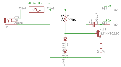

PCB size is correct printed at 600 DPI. (Please contact me for Eagle
PCB CAD
files.)
I realized later that I had neglected to include an onboard
(bright-off-dim?) switch. A PCB mounted switch mounted through the side
could potentially mount the whole circuit board to the side of the
light base with no other mounting screws.
If necessary for lowest voltages, a schottky diode
instead of one of the 1N4148
signal diodes would make about .9V forward drop instead of 1.2,
reducing the voltage across the sense resistor from .6 to .3 volts. But
then, too-low voltages will only result in dimmer light anyway, which
helps conserve the last of the battery power. If 11.5 volts doesn't
quite give full
brightness, I'll still be happy.
It turned out that even with a 360Ω bias resistor, 12
volts didn't give full brightness. I started with 4.7K. Okay, I admit I
didn't even think about the beta of the transistor. (BCIT was 1975.
That's, um, a while back.) Three diodes (or a zener - around 1.5 to 2
volts) and a darlington would be more stable with voltage changes, and
I'll try that in the next unit. The circuit as is is essentially
adequate and prevents serious problems with an unregulated supply.
Brightness still varies somewhat by voltage. That's not entirely bad in
a solar/battery setup: as the battery voltages drop, the lights dim to
retain the remaining charge longer.
Since it's
just a simple single sided PCB, and
since I
also need simple single sided boards for the motors, I decided that
after 25 years it was time to make my own boards again. A 'dremmel',
then expensive - now cheap, is a faster hand drill for tiny PCB
component holes than a drill press was.
I'd heard it
was simple to apply the artwork using a laser printer and ironing the
toner from transparency sheets straight onto the PCB, so I checked out
some instructions on the web. Perhaps the most detailed ones were from www.qsl.net/vk5cu/ , which
included a procedure for exporting the PCB artwork from Eagle PCB to a
"paint" program for convenient printing. That was fortunate, because
I'd never
have figured that one out myself. And in the paint program (Graphic
Converter) I drew circles around the too-small pads and filled them
using 'paint', to get larger pads more suited for single sided boards.
For etching it seems that ammonium persulfate has replaced
ferric chloride in the intervening years.
But one Australian had a
unique system with hydrochloric acid. I guessed the other ingredient
before I read it. Hydrochloric acid won't react with copper, but it
will with copper oxide. And copper can be oxidized with hydrogen
peroxide. Sure enough, that was the other ingredient. So: regular
hardware store hydrochloric acid (~33%) and regular drugstore hydrogen
peroxide (3%). He said with a 1 to 1 mix, it would etch a board in one
minute! (common is 10-30.) I'll try this when my 30 year old container
of ferric chloride runs out.
In fact, I already know it works - I used it to make
copper into copper chloride as an experimental battery electrolyte
chemical. But I
never connected it with circuit board etching!
Someone says salt and vinegar also works. Now there's a
safe etchant! You have to leave the board in overnight. (Would that
make copper acetate instead of copper chloride?... or sodium acetate
and copper chloride?)
I bought acetate transparency sheets and printed out the
PCB, then
ironed the toner onto the copper side of the PCB. It didn't fuse well
to the board, mushed around, and basically was crap. A second try
produced
only somewhat better results. But I etched it. It took an hour -
perhaps my ferric chloride from about 1983 is already pretty much
spent, or somehow it deteriorates over the years. I'd be ashamed to put
the board into anything I would sell, but at least it was a quick,
cheap first prototype. There were others unimpressed with the results
of iron-on toner artwork, but some boards looked pretty good. Perhaps I
should try thinner glossy magazine paper (as some recommended) instead
of acetate transparency sheets.
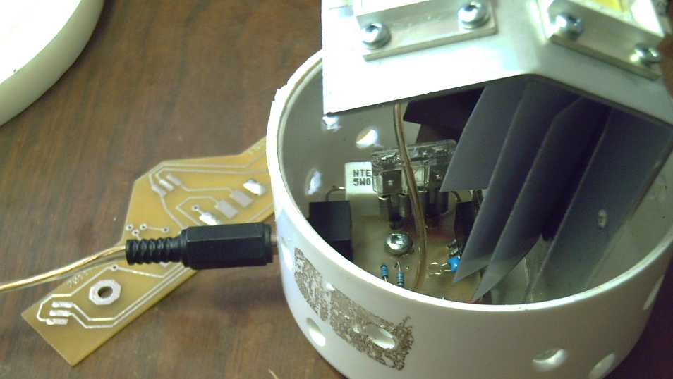
LED Circuit board populated and mounted in LED globe light base.
(To left is Electric Hubcap Motor magnet sensor PCB -
another of several simple boards it would be nice to do myself.)
With a small but
growing list of products needing simple circuit boards, they're best
made here as needed, and I have
another idea: I think a 3D printer might print just one or two layers
of plastic right onto the circuit board as thick etchant resist. If it
adheres, it should repeatably, easily and reliably make boards that
will etch very nicely - consistent production
quality if somewhat coarse in resolution. If it doesn't fuse onto the
copper very well initially, it probably will if heated above melting
point of the
plastic after printing.
If the plastic won't
come off easily afterwards, it can be dissolved off with methylene
chloride. ...Or
maybe left on as a mask except where solder goes.
I'm surprised that I can't find any mention of this idea
on the web. No one doing PCBs or 3D printing at the Maker Fair on the
29th had heard of it, either. Given what a great idea it sounds like,
somebody should at
least mention if it doesn't work well.
So!, 3D printed PCB artwork, and custom 3D printed globe
bases with all desired vent holes and mounting protrusions premade!
With clearer plastic, perhaps even globes could be printed. I might be
able to make LED lights economical enough to get customers after all.
Turquoise Battery Project
Work on this project is essentially on hold until I
assemble
the 3D printer. Then I still need to get familiar with the software to
run it, packages such as TinkerCAD (3D CAD - STL files), Slicer (breaks
it onto "n" 2D layers to print), and Pronterface (makes it into G-Code).
Of course I continue to consider how to make conductive
plastic electrode pockets. I
found a source of conductive ABS printing filament on line
(repraper.com) and ordered 2 Kg of it. But the contact and internal
resistance is so high as to make it seem almost useless for batteries.
I'm thinking that a local plastic place could probably
churn out zinc powder conductive filament... the question is how big a
batch they'd want me to take to do so. Another option is there seem to
be some new desktop machines for making 'scrap plastic' into filament.
This is likely to prove more practical if anything is.
I got on the web again, looking for "filamentary zinc
powder", thinking a smaller amount of filaments in plastic - or in an
Mn negode itself - would conduct better than the same concentration of
small "dimensionless" granules. I didn't find any, but I found and
ordered some fine "zinc flake powder", which also has the 2D attribute.
Perhaps zinc flakes or carbon fibers could simply be
sprinkled onto the plastic, then a heat gun could melt them in to make
them stick. It's something to try, anyway.
I thought I'd also look into osmium powder again, since
osmium
doped acetaldehyde painted on the graphite/grafpoxy seems to make
higher conductivity. Last time the best I could find was 90$ + about
65$ shipping for a gram from a chemical supply company. This time, I
looked for the metal, and found a company RGBco
(www.element-collection.com), with pellets of it: 5g for about 180$
plus 15$ shipping from the UK.
They were on holidays, and when I got tired of waiting I
found a USA place with similar prices and ordered some.
Lastly, someone claims to have made a battery that
harvests energy from ambient temperature heat - the same nuclear energy
source I suspect magnet machines use. If a technique can work at the
individual atom level, "entropy" can be modified if not reversed, since
the 'laws' of thermodynamics are based on average transference of heat
between atoms in a system. For a well known example, heat can be pumped
from a cold place to a warm one using less energy than the amount of
thermal energy transferred.
Details were scarce, but the battery uses graphene
electrode contacts and copper chloride electrolyte somehow. Copper ions
evidently reach high thermal speeds within the solution, and the energy
of this motion can move two electrons from/to the graphene and hence
through an external circuit. Six such cells lit an LED, so they were
probably about 1/3 of a volt each.
Here I am doing cells with doped graphite based current
collectors for the positive electrodes and a chloride based
electrolyte. Copper chloride should be compatible. I should see if I
can find more details. I suspect that even if the principle works, and
even if it can be employed in my cells, it would take a long time to
get a decent charge... but a battery that gradually charges itself
instead of gradually losing charge would be, to say the least, amazing.
http://www.TurquoiseEnergy.com
Victoria BC