Turquoise
Energy Ltd. News #56
Victoria BC
Copyright 2012 Craig Carmichael - October 2nd, 2012
www.TurquoiseEnergy.com
= www.ElectricHubcap.com
= www.ElectricWeel.com = www.MushroomOutboard.com
Hilights: Car Moves with Planetary Gear Torque Converter:
variable conversion principle proven!
12 Volt DC "CAT" Standard Plugs and Receptacles: a specification defined (RFC - request for comments?)
Month In Brief (Summaries)
- Just in time torque converter - my BCIT/VEVA talk on my projects
including torque converter - heat pumping - 12 VDC wiring and plug & receptacle specification "CAT" defined - 3D printer almost ready
In Passing (Miscellaneous topics
and editorial comments)
- Iran - NAM summit - Financial collapse to free world from dead-end grip of corrupt kleptocracy
Electric Hubcap System
* External PWM for Motor Controller in Sprint car
* IR2133-V2 motor controller woes (-V1 worked great throughout tests!)
Planetary Gear Torque Converter
Project
* Torque converter mods & tests #2 to #5, Sept. 6, 8, 10, 12: No go.
* #6, Sept. 14th: Doubtful "last chance" rope balancing idea gets
car moving nicely, proves PGTC idea is a viable variable transmission.
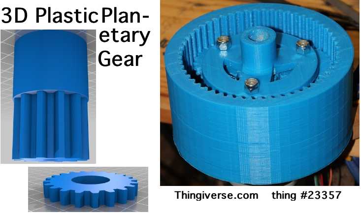
* Next plan: 3D print a plastic planetary gear to order, with drive belt pulley on the outside rim.
Solar Electricity Project
* "Smart" fridge control
eliminates use of backup batteries
or grid power to run solar powered fridges: sensing supply voltage and
allowing slight overnight temperature rises should almost eliminate
running superinsulated solar fridge except when sun is shining.
* 12VDC Main Breaker Box
* 12VDC Standard receptacle & plug definition
Superinsulated Thermoelectric Fridge &
Freezer - Peltier Module Heat Pumping
* Further fridge construction work
* Stronger Peltier module
* Melting ice as overnight cold storage with 'smart' solar fridge control
Magnetic Heat Pumping
* Designs and materials
* Attaining strongest field from permanent supermagnets
* Test on first "stack of [2] boxes" discloses design problem: Cu magnetic
heating. Changes are required.
No Project Reports on: Magnetic Motion Devices, Weel
motor, DSSC
solar cells, LED Lighting, Pulsejet steel
plate cutter, MnMn Turquoise Battery project
Newsletters
Index/Highlights: http://www.TurquoiseEnergy.com/news/index.html
Construction Manuals and information:
-
Electric Hubcap Motor - Turquoise Motor
Controller - 36 Volt Electric
Fan-Heater
- Nanocrystalline glaze to enhance Solar
Cell performance - Ersatz 'powder coating' home process for
protecting/painting metal
Products Catalog:
- Electric Hubcap Motor Kit
- Sodium Sulfate - Lead-Acid battery longevity/renewal
- NiMH Handy Battery Sticks, Dry Cells
- LED Light Fixtures
Motor Building
Workshops
...all at: http://www.TurquoiseEnergy.com/
(orders: e-mail craig@saers.com)
September in Brief
In two days the Sprint planetary gear torque converter
tests #1 video on youtube, posted September 3rd, hit 100 views, not without some publicizing.
Looks
like people are interested. Of course, I was eager to modify the motor
controller and try again. I put together and installed an external PWM
board on the 5th, and tried it out on the 6th. And on the 8th. And on
the 10th. It seemed like a vicious circle, but I gradually figured out
the repeatedly exploding motor controller and the mechanical twisting,
binding gears problems.
A couple of observers of the test on the 10th said things
seemed to be twisting and binding. For the test on the 13th, I cut a
big hole in the middle of the pulley so it fit right over the ring
gear (_just_ made it), and I remounted it on the other side of
the flange on spacers so it was right in the center of the gear teeth
instead of off to one side. No more twisting! But it didn't work any
better.
I started thinking: the planets assembly was poorly supported - it had no bearings
at all. It just floated between the sun gear and the ring gear. If the
forces weren't entirely balanced around the axis, could it shift far
enough to one side that the teeth didn't mesh right? That seemed a
little far fetched. But there was one more thing I could think of try: having one tension rope
go around under the pulley and one over it to roughly balance the
forces.
I got this partly assembled on the morning of the 14th,
but a bracket at the front tied to the shift-clutch lever would take a
while to make... for an idea that didn't seem very likely to work
anyway. I came out late in the afternoon and looked at it... what if I
used the test control at the hood (in spite of it allowing the motor to
easily stall) and just grabbed the ropes with my hand like I did on
test 1? This resulted in quick success. When I had the ropes held
right, the car eagerly started to move and seemed to almost jump ahead!
At long last, this proved that the slipping planetary gear torque
conversion principle works. I had set up my cellfone as a camcorder, so I got a video of this brief event.
Subsequent measurements
showed only around 40-50 foot-pounds of torque to the wheels with 35-45
amps on the motor. But that was at least double what it had before, and
the two shafts were only nominally aligned. It was likely things were
still binding in there - just less than previously. I'm pretty sure
there should be plenty of torque
to put it on the road with adjustments. And I hope to 3D print a
plastic custom planetary gear made for the purpose, large and with more
planet gears to spread the loads out. This would mount on one shaft
with independent bearings on planet assembly and ring gear, and need no
fine adjustments.
Like proving the battery chemistry before my Ideawave talk
in February, this success was pretty much in the nick of time, as I had
accepted an invitation to talk about my projects, with emphasis on the
torque converter, at the VEVA [Vancouver Electric Vehicles Association]
meeting at BCIT in Burnaby on the 19th. The talk was well received, and
one person seemed eager to start making/producing my new chemistry
batteries. I'll assist that process every way I can. When my 3D printer is ready I can start working out production details
myself.
 Having the whole drive assembly out of the car
because I'd taken it to show at my talk, I resolved to switch it to
belt drive instead of chain, and to make a cover to keep out road dust.
I spent a couple of days looking for parts for toothed belt drives, but didn't come up with a
satisfactory set - just one nice surplus motorcycle wheel pulley that I
probably couldn't get a belt for, of the length I needed.
Having the whole drive assembly out of the car
because I'd taken it to show at my talk, I resolved to switch it to
belt drive instead of chain, and to make a cover to keep out road dust.
I spent a couple of days looking for parts for toothed belt drives, but didn't come up with a
satisfactory set - just one nice surplus motorcycle wheel pulley that I
probably couldn't get a belt for, of the length I needed.
I finally decided that the way to go was to set it aside
for the moment, order an appropriate belt, and 3D print matching custom plastic
parts to fit the Sprint. I found a whole batch of "parametric pulleys"
on thingiverse.com including the desirable 8mm HTD tooth pulley
(deeper, rounded teeth), designed for me in OpenSCad. It could be
modified to have any width, number of teeth, shaft hole diameter, etc.
Meanwhile, I figured out how to get more magnetic flux
from supermagnets in order to change the temperature of the gadolinium
more, and I found some suitable materials and mocked up a stack of
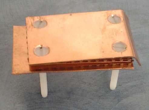
gadolinium powder mini-boxes with real copper and plastic pieces.
Someone suggested I use plastic machine screws instead of metal to
prevent them transferring heat from the hot to the cold side. Great
idea!
 When I tested it, the whole box got warmer. Then I
realized the magnets were running across copper and of course
stirring the electrons in it and heating it up. This overpowered the
magnetocaloric effect.
When I tested it, the whole box got warmer. Then I
realized the magnets were running across copper and of course
stirring the electrons in it and heating it up. This overpowered the
magnetocaloric effect.
The magnets and copper can of course be brought together
without sliding them across each other. It'll just take a new, more
mechanically complicated plan.
But with magnetic heat pumping looking less promising of
immediate results, and needing a stronger fridge cooler for a smart
solar fridge control
and winter coming on, I decided to order a dozen
peltier modules and parts to make fridge coolers and a home
heat pump, or perhaps an electric car heat pump. Somehow, my mind wants
to
prove the straightforward peltier module heat pumping concepts even tho
the magnetic heat pumping would be far more effective. Belatedly after
placing this 200$ order, I shopped around and found some places with
Peltier modules for 1/2 Digikey's price. That makes the heat pump ideas
much more affordable, since the Peltier units are the bulk of the cost.
The Digikey price greatly lengthens the payback period.
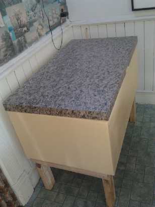

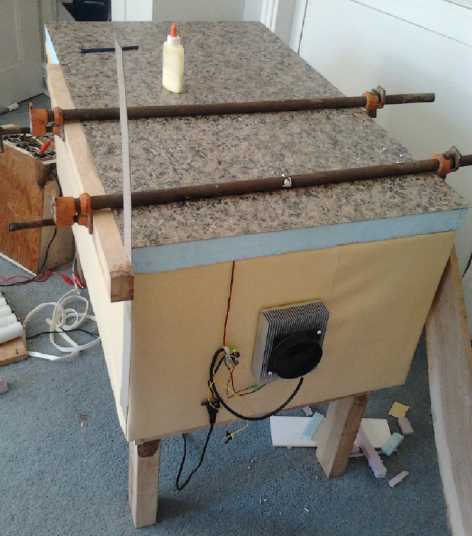
The solar powered 12 volt Superinsulated Peltier fridge in the kitchen.
The top is 2" extruded styrofoam (R5 per inch); the rest is 3+" with an inch of polyurethane (R7 per inch) added inside.
(Okay, it could use a few finishing touches.)
Finishing the basic fridge construction and moving it to the
kitchen immediately brought on the DC house wiring issues -- of finding
or creating some sort of 12 V DC standard plugs and receptacles,
and
creating some sort of standard Main DC Power Panel. Such
creations seemed to call for
making plastic parts with the 3D printer, yet such parts wouldn't have much tolerance for heat.
12 Volt DC Plugs and Receptacles - Proposed "CAT" Standard (RFC)
The closest thing I know of to a
'standard' 12 volt plug & receptacle is presently the car cigarette
lighter type, which bulky design was never intended for such a purpose.
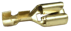 My proposed CAT (Connector-AT) standard for plugs and receptacles is
based on the ATC/ATO automotive fuse system, with the same 5mm wide
blades and common 'universal' sockets (commonly available - see image)
making the connections and with the same 9 to 9.5mm blade center
spacing, but with the negative terminal turned sideways. Turning one
blade sideways ensures the correct polarity, puts sufficient space
between the two pins, and ensures a fuse can't be mistakenly plugged
into a power receptacle or vise versa. That ATO fuses are available up
to 40 amps suggests the contacts are good for considerable currents. As
it is intended for battery power circuits which are only nominally 12
volts, my spec tentatively says the voltage range can be 11.0 to 14.5
volts, and equipment should be designed to handle this range. (Ideally
heavy loads should turn themselves off below 11 volts to conserve
batteries.)
My proposed CAT (Connector-AT) standard for plugs and receptacles is
based on the ATC/ATO automotive fuse system, with the same 5mm wide
blades and common 'universal' sockets (commonly available - see image)
making the connections and with the same 9 to 9.5mm blade center
spacing, but with the negative terminal turned sideways. Turning one
blade sideways ensures the correct polarity, puts sufficient space
between the two pins, and ensures a fuse can't be mistakenly plugged
into a power receptacle or vise versa. That ATO fuses are available up
to 40 amps suggests the contacts are good for considerable currents. As
it is intended for battery power circuits which are only nominally 12
volts, my spec tentatively says the voltage range can be 11.0 to 14.5
volts, and equipment should be designed to handle this range. (Ideally
heavy loads should turn themselves off below 11 volts to conserve
batteries.)
Since the receptacle is smaller than the end of a
cigarette lighter plug, equipment manufacturers wishing to adopt the
standard but unsure whether the customer will have the socket to plug
into, need only supply a cigarette lighter adapter with the new
receptacle on it - even if no one else were to adopt the new standard.
The pressing need for a standard hitherto lacking and the ease of adoption should ensure rapid spread.
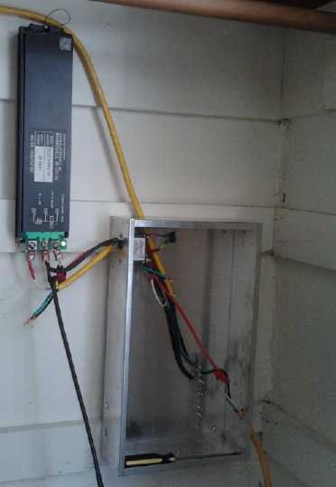
Starting the 12 VDC house wiring: DC to DC converter and unfinished main breaker panel in a second floor closet,
that conveniently has access to a crawl space between floors where wiring is easily run.
When I finally got back to it on the 28th, I
found it had been for over a month sitting just 2 hours away from
"Mechanical assembly is now complete." I also wired up the power
supply and mounted the PC board. That just leaves wiring it up and trying it out - and no doubt a bunch of small adjustments.
In Passing
Incidental news, editorial opinions
When I was a kid I read a one or two page comic in a MAD
magazine. The setting was a county fair or something with many people
sitting at outdoor tables having lunch. One lady says "There's that
awful Mrs. Chiquenphat! It wouldn't surprise me if she's doing..." I
can't remember the nasty things that were said, just the jist of it.
Another lady replies "Yes, and I'll bet she's..." The third lady chimes
in with another accusation, and the innuendo gets very thick. It ends
with the three ladies glaring, livid with rage, "Ooh that conniving
Mrs. Chiquenphat!", as Mrs. Chiquenphat sits oblivious at her table
sipping her tea. All the trouble originated in the minds of the three
ladies. The present jihad against Iran reminds me of this comic.
Iran has moved onto the world stage as a diplomatic player
by hosting the 16th NAM conference in Tehran, with representatives and
even leaders of 200 countries in attendance. Some have said NAM is the
real international community. Canada has responded shamefully by
closing its Iranian embassy and breaking off diplomatic relations,
without even a pretext, and is towing the USA line with warships in the
Persian Gulf. Canada's loss.
I don't know if Iran is building nuclear weapons, put it
has nuclear Pakistan, India and China to the East, nuclear ex-soviet
republics to the north, nuclear Israel uttering serious threats of
aggression not so far to the west, and nuclear USA occupying
Afghanistan and Iraq on either side as well as the Persian Gulf
(Iranian coastal waters) with naval forces, sponsoring a ruinous
embargo and also uttering serious threats. That leaves Turkey on the
north-west as the only "non nuclear" border state. For "surrounded by
nukes" Iran not to acquire its own nuclear weapons as a deterrent in
general and in response to explicit threats in particular might be
considered an act of considerable forbearance, and perhaps even
disregard for citizens' safety and national interests. What country
might Iran profitably scheme to attack? What would be her incentive to
build nuclear weapons if other nations weren't oppressing and
threatening her? The USA and Israel seem to be intent on creating the
nuclear armed hostile Iran they profess to fear, by their own hostility
and aggression.
We are all connected. We
are all one. And what has always been true at the spiritual level
almost
suddenly seems manifest at the sociopolitical level. Oppression,
tyranny,
and
economic and financial degeneration aren't isolated to any one country,
region, or continent,
but are manifested globally in various forms, and few lands are outside
its grip. And there are some few reprobates who work behind the scenes,
trying to turn the
whole world into a feudal slave camp. For them, destroying vast numbers
of
people is just a part of their agenda. Their chilling plans make
Stalin's purges and Hitler's holocaust look moderate and restrained.
Europe is coming apart at
the seams and populations under stress are taking to the streets. Half
the population in the USA now receive some form of government
assistance as the economy deteriorates unabated. It will surely implode
when the financial crisis hits home. China suddenly has great
masses of unemployed as trade dwindles. Other regions
are simply dragged in by what's happening in these major blocks. Canada
may well fare better than the
USA, but major
changes are clearly in the wind. How is it that even the Australian
government
seems caught up in tyrannizing its
own people? We are all connected. Only in a few small places or on
isolated issues have people managed to retain or regain a measure of
control over
their affairs.
How may things unfold? Rather than a sudden surprise
collapse in a few months, I now think we're in for another year or two
of
gradually worsening conditions, with escalating prices of food and
energy and consistently more bad news than good - then the financial
crisis will come almost as "well, that figures", logically following from everything preceding it.
Notwithstanding, I think far too many people won't realize the serious implications beforehand, and will be caught with bare
cupboards and no food gardens when the consequent disruptions to organized supply and
distribution ensue.
One can only watch as the
awesome divine plan for the eventual rescue, liberation and progress of our
"stuck" world begins
to
unfold, and do our best to be our best, to daily pray for guidance and
reflect quietly for a few minutes to discern any answers that may be
proffered, and to try to make
ourselves part of the solution rather than part of the problem. A
better world is made by better individuals, and that's the only way it
will be made. Be awake. Be open. Learn. Share. Live!
Electric
Hubcap Motor System
Magnetic Heat Pumping to Extend Winter Vehicle Range?
If magnetic heat pumping could make for better
refrigerators, low voltage DC refrigerators, and heat pumps for home
heating with less energy, it would be even more valuable in electric
cars where all the energy is stored on board, and the additional draw
of an electric heater notably reduces available driving range in winter.
Think of an 800 watt, 36 volt electric heater like the one
I made about 3 years ago (thinking I'd soon have a car running on
electricity - hah!), and then imagine a unit making the same heat with
200 or 300 watts. Instead of using a horsepower, it's 1/3 of one.
Thus the projects come full circle from electric transport
to solar energy to peltier refrigeration to magnetic heat pumping and
then back to a potential valuable use of that in electric transport.
And if it works out right, the heat pump car heater could double as an air
conditioner or a camping refrigerator in the summer.
PWM Motor Control
The August 30th tests showed that the 'CRM' type of
modulation allows the motor to be slowed and stalled much too easily,
because the current and hence torque doesn't rise with dropping speed
like with most motor control systems.
That could work well enough with some torque converter or
boat propeller where the load increases with speed, but it doesn't jibe
with the planetary gear converter where the load changes with rope
tension regardless of speed. The motor simply stops almost before you
can 'give it more gas'.
I decided to put a trimpot or fixed resistors on the
existing CRM voltage input to set the current limit, and modulate the
_MotorOn_ signal with an external, inverted, low frequency PWM. The CRM
would limit the current under all circumstances, regardless of RPM, and
the PWM would provide the more common sort of control, where the loaded
motor works harder and harder to keep spinning as it slows down.
This seemed advantageous over either system by itself.
CRM = current = torque
PWM = average voltage
CRM (fixed current setting) * PWM (avg.V) = power
Thinking back to 2008 and 2009, I thought I had made some
sort of PWM circuit board. A check of the shelves uncovered a 555 timer
based PWM generator on a proto-board. Just the thing - one piece of
work already done. And I found a schematic for it and made some
changes. It ended up like this:
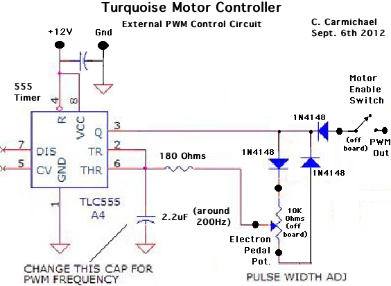
The 555 PWM circuit has
the interesting property of going
neither to 0% or 100% - there's some short time of charge or discharge
that limits it to perhaps 2% and 98%. After trying this, I decided it
was an advantage. The slight purring sound of the 2% modulation gives a
warning similar to the idling of a gas car. It warns the driver and
anyone nearby that everything's now live, and the car will start to
move
when the pedal is pressed. Potentially that's a lifesaver compared to a
silent car that suddenly starts moving with no warning. I actually find
that a bit unnerving, whether driving or standing nearby.
I built and installed it (hanging by its wires from the
terminal block under the dash) on the 5th and tried a second testing
on the 6th
with this PWM generator feeding the motor on-off switch, thus combining
CRM and PWM. The CRM was set to 50% control voltage by two equal 5K
resistors. The rope still worked to keep the motor from starting, or
from picking up much speed when it did. I remembered there was a
considerable 'dead band' offset voltage so that 1/2 voltage was
probably considerably less than 1/2 current. A good point however was
that the stopped motor no longer kept shutting off owing to loss of
charge on the active bootstrap capacitor.
I upped it to 4.7K/2.2K - 68%. That still didn't seem to
have a lot of power, and I changed it to 10K/2.2K - 82%. I finally
thought to hook up the DC amp probe and found it was only reading
around 40 amps (average). The car still didn't move, and I finally
upped it to full power, which I calculated last month as reaching about
160 amps (peak). This time when I floored the pedal it blew, just like
the last time I gave it full power.
And yet, this was puzzling. When I made the first IR2133
controller and tested it with a motor on the bench, I saw many
readings, however briefly as the unloaded motor rapidly accelerated, of
80 or 90 amps, even 100, and nothing blew. It worked fine. What was the
difference?
I decided I'd better limit current with the 10K/2.2K, and
also change the PWM so it didn't have more than 70% 'on' time even with
the pedal floored, in order to give the system a rest rather than
virtually continual operation. The duty cycle limiting was accomplished
by adding a 3.9K resistor between the upper side of the pot and its
diode.
Next time I feel adventurous I'll try full CRM power
again, but with the 70% max PWM instead of 95+%. I think
that'll work. Or the 10K/2.2K voltage divider and maybe 80-85% PWM duty
cycle. But obviously the controller can't handle 100% power and
(nearly) 100% duty cycle.
I decided I'd rather ignore the controller issues and try
and figure out why the car
won't move with whatever small amount of force is available. It was supposed
to be an infinitely variable torque converter, and I wasn't convinced
it was delivering the torque increase it's capable of. The car should
be
moving, even if it didn't get up much speed.
This proved to be a bad idea and the controller burned up
for the third time (phase B every time). Along with the blown mosfets,
I was replacing the 15$ IR2133 every time (it was socketed) because it just
wasn't worth having the controller blow again immediately when power
was applied if it was damaged, and this was the last one that didn't
have "?" penciled on the top. On the 8th I had continued the tests by
dragging out the IR2133-V1 controller. It seemed to work okay and it
didn't blow. What was the difference between V1 and V2? I remembered
that owing to the IR2133 (a 12 volt chip) not accepting 12 volt logic
signals, I had added a 5 volt regulator. Furthermore, I had used a
resistor pack, now tied to 5 volts instead of 12 volts. I looked at the
schematic and realized that the timing capacitor for the "fixed time
off" of the modulation that prevented disastrous currents would
discharge to logic low more quickly from the lower voltage. Owing to
the behavior of the logic with the 'overvoltage', there was probably no
simple mathematical relationship for the capacitor value, and I wanted
to get the car going, not get into detailed bench testing again. I
simply doubled it from .0022uF to .0044uF, and in the tests on the
10th, the controller didn't blow.
It also only got up to about 35 amps max, and that was
with the CRM set to max. I decided to remove the extra resistor from
the PWM and allow the "98% ON" full power setting again.
But the next day before I got to it I went to show the
system to someone, and the controller blew the first time I started the
motor in reverse, not even at full power. Later I discovered that the
current sense wire was loose. (How many times did I check that wire?
Apparently one less time than I took the controller apart and fixed it
again!) Now I don't know if the burnout was because the capacitor is
still too small, or if the wire lost contact - which certainly would
blow it. But I started thinking it should be clamped down separately,
rather than under one screw with 2 other wires.
In the tests on the 12th and 14th, I used the "V1"
controller
again. It put out 40-50 amps a couple of times. That made me very
nervous since 40+ was about where the newer "V2" started blowing, and I
tried not to push it too hard. But the V1 had put out 60, 70 or 80 amps
on the motorbike before and up to 100 on the bench, so why should I be nervous? It worked fine
throughout - unlike the torque converter.
On the 15th some smoke came off it in a more extended
test. I didn't hear a pop, and it hadn't quit. It seemed the thinner
wires I'd used to balance the currents between the transistors had
heated up and the insulation was smoking. The controller was otherwise
fine, and the transistors themselves were still cold. Now I know that two #18 wires is too small even in very short lengths.
Installation as of about September 10th, minus motor controller
Battery Plugs
On the 11th and 12th I also decided to make plugs for the
battery and put a cover on it, before I dropped a wrench across some
battery terminals or something. I used APP-70 amp connectors, same as
on the motor wires, and I 'plugged' the batteries and the power wires
of both motor controllers.
Next were three APP-30 amp plugs for the three 13.8-volt,
5-amp battery chargers. I prefer to charge each 12V section
independently. This is even more valuable for lead-acid, and vital if
they're not identical, since it prevents weakness, failure or
difference in capacity of one battery from affecting the others.
One thing I didn't think of, though I thought I had tested
carefully, was how hot wires get if there's heavy currents in them.
Evidently the third plug had the red tape on the wrong wire - and a
moment after plugging it in, the insulation melted, and it melted the
insulation of the next wire, causing more shorts. Luckily the wire was
only about #16, and three of four wires melted through, ending the
short circuits. I had to blow out the flames twice as the insulation burned. The chargers were
undamaged and the batteries didn't explode. Only the melted wiring was
there to remind me: "triple check next time."
An interesting basic video on Belt Drive Design:
http://www.youtube.com/watch?v=nMsB6Soz4Hc . unfortunately, I still
haven't found any info on what type and size of belts to use for how
much power at how much speed.
Planetary Gear Torque
Converter (PGTC) Project
I added a little piece in
the gear to block the pulley from shifting sideways and rubbing on the
housing, reinstalled the motor and controller, and then tried a second
testing on the 6th. The torque
wrench on the front wheel center nuts
disclosed that it took around 60-80 ft-pds to move the car either
direction from where
it sat on the rough lawn. The
rope still worked to keep the motor from starting to turn, and from
picking up a lot of speed when it did start. This friction, or pulling
the lever to add more friction, didn't seem to translate into moving
the car. At one point I felt it starting to budge, but that was all.
In the first tests, the successful roll forward and the
start of a roll backwards came when I disconnected one end of the rope,
started with it quite loose, and pulled it by hand. I thought I was
pulling pretty hard, but perhaps it was still less friction than it had
wrapped around the pulley, however loosely tensioned.
But this set of
tests became mostly trying variations of motor controller operation
with the new PWM circuit to try and get more current out of it. Where
I've been talking all along about
127 DC amps, it's only getting up to 40 without trouble. That's only 1440
watts/2 HP, instead of 4572 watts/6 HP. Of course, average amps
is substantially less than maximum amps - looks like maybe it's
only about 30% rather than 50%.
After blowing up the motor controller again trying to get
more current,
I took off the rope and figured out another way to attach it, with a
coat hanger wire, with less rope wrapped around the pulley, maybe 150
degrees instead of 180.
It still didn't allow free turning. Evidently that would
take running around the bottom of the pulley instead of over the top.
There it would hang down, instead of falling into the pulley's V slot.
But perhaps it was now slack enough.
I had the controller repaired on the 8th, but it almost
immediately blew again. This time I got out the other controller and
hooked it up. With exactly the
same hookup, it seemed to keep working fine. Later I determined that
with the change from 12V to 5V
logic, a capacitor value should have been increased to give similar
"fixed off time" in the modulation - it had been inadvertently
shortened. I doubled it from .0022uF to .0044uF.
With currents of 40-45 amps, it still only moved the car
forward, not backward, and only if the torque needed was 20 foot-pounds
or less. A couple of DIY people happened along. It was remarked that 40
amps times 36 volts was only somewhat over a kilowatt. I said that was
true, but I
thought that if everything was working right, a kilowatt should move
the car. The torque converter should be able to provide, eg, 100 to 1
torque advantage, and it should move. At that point, one checked out
the gear system. He said there seemed to be a lot of friction if it was
pushed even slightly sideways. Sure enough, this was true. It almost
locked up at some points.
The helical gears pushed the converter gear elements
strongly sideways at the same time as they turned it. There was nothing
that intrinsically held them together in proper position. In its
original transmission the forces must have been quite symmetrical
around the axis. But here, nothing was
locked laterally on the shaft, except to prevent the whole thing from
spreading apart, so the gear elements were moving and, evidently,
jamming. The
power of the motor was being wasted rubbing the gear elements together.
I took it all apart.
I started to long for that big plastic planetary gear with
its straight teeth. Nothing would twist in 2+" wide gears, and there'd
be no lateral forces. It was starting to look like the 3D printer was
the solution for this project as well as the others. I phoned someone
I'd met at the Victoria Maker Fair, and he told me about (a) a program,
OpenSCAD, for creating 3D objects from CAD drawings or by entering
numeric parameters (eg "cube([2,3,4])"), which seems very nice, and (b)
a website, "thingiverse.com", that is the main repository for 3D
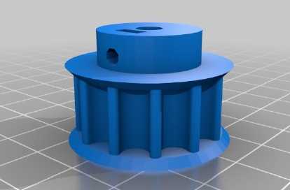
designs released to the public domain. I found planetary gears there.
Here's the one I liked best:
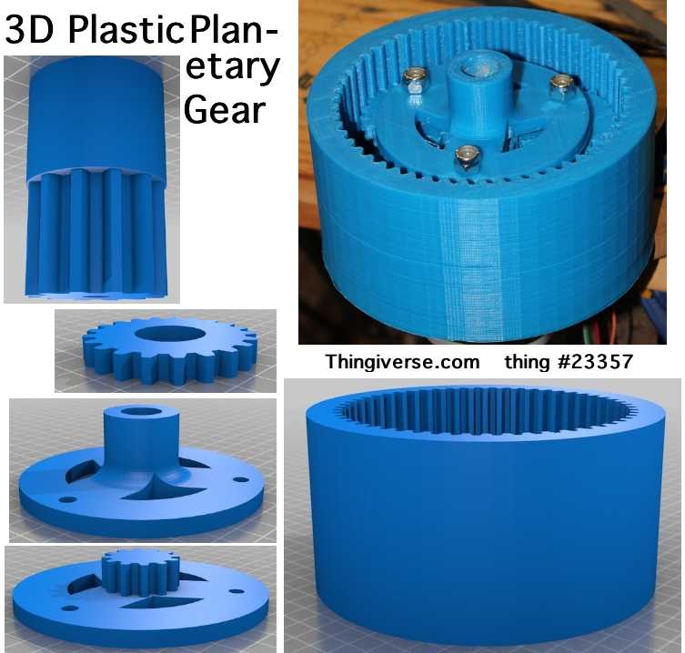 It was probably about 4" diameter. If that was
scaled to 5 or 6", it would probably look pretty "industrial".
It was probably about 4" diameter. If that was
scaled to 5 or 6", it would probably look pretty "industrial".
Then if the planet gears and the sun gear teeth were made
as wide as the teeth on the ring, about 2" wide, and if four or five
were used instead of three, the load would be spread lightly over a lot
of plastic. Scaling and dimension changes are simple parameter changes
in OpenSCAD.
This sun gear has a feature the metal one doesn't: a
shoulder that won't let the planet gear assembly slide out as it turns.
The next thing I'd add would be a flange/cover over one
end of the ring gear. This would be similar in form to the left image
2nd from the bottom, and would fit on a 1" round shaft with a key.
Better still, there could be teeth on the outside of the
ring gear for a toothed drive belt, maybe with .5" spaced belt teeth.
With the ring being its own belt pulley, the center of the flange would
be made to hold 1" I.D. bearings, as the shaft wouldn't have to turn
with the ring.
With this arrangement, the entire assembly could be
mounted on the motor shaft. In that case, I'd probably want to extend
the motor shaft to the far side of the enclosure and put a bearing
there, its exact position adjustable. There'd be one continuous solid
shaft through the motor, the PGTC and crossing the differential
position. That should form a pretty sturdy mounting for the drive belt
to the differential.
A "herringbone" tooth pattern (easy to do with 3D printed
gears - difficult with cut steel) was mentioned as a smoother running
alternative to straight teeth, but which didn't pull to one side like
helical. It has a serious drawback for a planetary gear however:
there's no way to put the gears together, unless the outer ring gear is
made in two halves or something.
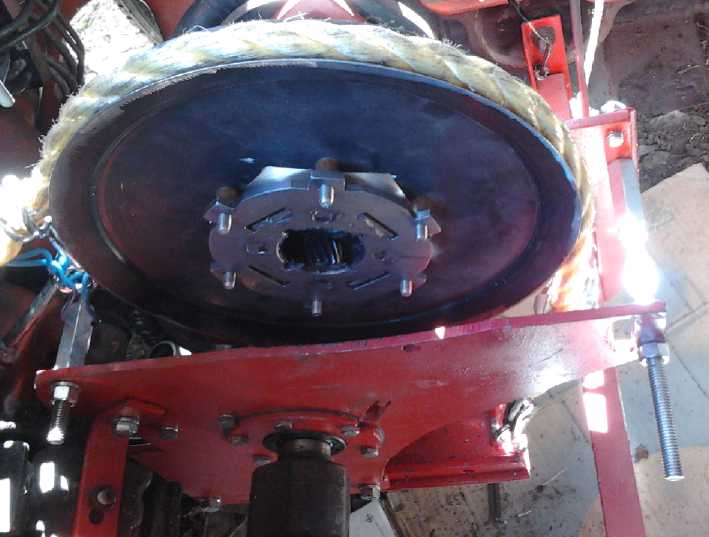
Meanwhile, back at the existing metal planetary gear, I
drilled holes in the end 'flange' on the ring gear and put in set
screws to prevent it from "sucking in" towards the motor on the shaft,
which could be what was pressing the planets against the sun gear even
in forward. The grooves already worn into my cludjy mild steel part
holding the planets assembly showed that the sideways forces were a
major concern.
The shoulder on the plastic sun gear gave me the idea to
put a fat "shoulder" washer behind this sun gear as a better way to
keep the planets from sliding sideways when in reverse. But as it
happened the spacing would have been wrong and the idea got complicated.
 I tried again on the 10th with just set screws to hold the
ring gear from sliding on the shaft. With max current adjustment, it
would still
only deliver up to about 30 or 35 amps, and it didn't blow a 40 amp
fuse. But mechanically things were pretty much the same.
I tried again on the 10th with just set screws to hold the
ring gear from sliding on the shaft. With max current adjustment, it
would still
only deliver up to about 30 or 35 amps, and it didn't blow a 40 amp
fuse. But mechanically things were pretty much the same.
I stared at it for a while. The forces were all balanced
-- weren't they? No, because the rope pushed down on the pulley but not
up. And
the pulley was at one end of the planets assembly, so with the rope
pushing, it was trying to twist the planets assembly, jamming things.
That might explain why the car seemed so reluctant to move.
I decided the best thing to do would be to cut the center
out of the pulley just inside the flange bolts, so it would fit right
over the whole ring gear, and mount it on the inside of the planets
flange instead of the outside, and with spacers to center it on the
actual planet (and ring) gears. Then the force would be straight down
on the gears. (unless the rope was pulling to one side.)
I cut out the pulley center on the 11th and tried it on
the 12th. I changed the rope to match the new position of the slip
pulley, and then again as it still seemed to be jamming the motor from
turning at times. Somehow, it
didn't seem any better.
There was one last trick I could think of to try. The slip
clutch rope was still an off-axis push, even if it wasn't twisting
the pulley/planets assembly now. I could have ropes going under the
pulley and over it, so the pull would be almost completely balanced.
This wasn't going to be very simple, and the chances of it making the
big difference that was still needed seemed slim.
Trying again on the 13th with no new ideas, I monitored
RPM and found out that it topped out right about 2000 RPM (the grease
in the gears has a lot of friction), so there was no need to worry
about over-revving. But results were no better.
Where were the
rates of slip hiding that would give those 50 or 500 to 1 reduction
ratios? There should be power to
move the car reliably on the lawn
with even 4 or 5 times speed reduction/torque increase in the torque
converter, but it seemed closer to
zero. What was I missing?
On the 14th I considered that the planetary gear
assembly
had no bearings - it just floated around between the sun and ring
gears. It was never intended that there be off-center forces. And this
one had only four planet gears instead of five, allowing it to be
shoved sideways more by unbalanced forces, where it might well bind. I
decided
to bite the bullet and make the balanced rope system. I got as far as
getting a longer rope, now needed, and making up a clamp and attaching
the middle of the rope at the back of the motor. I was then faced with
the need to make a somewhat complex bracket at the front... that might
well achieve nothing useful.
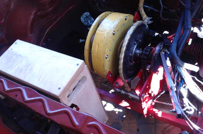
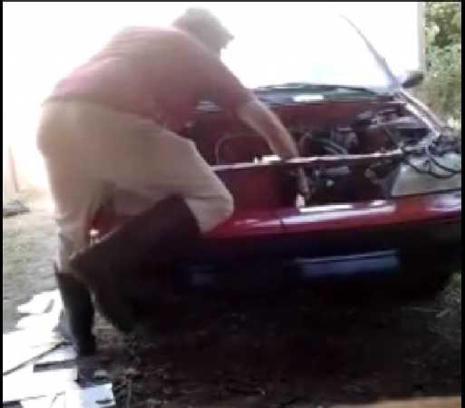
(Click picture for video)
 Later in the afternoon I came out and looked at it. Hmm...
What would happen if I used the test controls at the hood to turn the
motor and
just grabbed the ends of the rope with my hand? Perhaps I could at
least get an idea of whether there seemed to be any improvement?
Later in the afternoon I came out and looked at it. Hmm...
What would happen if I used the test controls at the hood to turn the
motor and
just grabbed the ends of the rope with my hand? Perhaps I could at
least get an idea of whether there seemed to be any improvement?
To my surprise, when everything was right and I tightened
the ropes, the car rolled forward quite easily! I had set up my
cellfone to "camcorder" to review anything interesting, propped up against a piece of wood on the bench, and thus I
captured this moment of 'hitting the jackpot'.
Further tests didn't get the car to roll back appreciably,
and it still had to be on a good spot to roll forward. But many spots
would now do, not just one where it was ready to roll forward by
itself. If it would do maybe 20 foot-pounds max before, now it was
maybe 40
or 50. The motor didn't have much of a flywheel effect, and if it
needed 80 foot-pounds, revving it up and 'letting the clutch out'
didn't
get it very far - it would start moving, the motor would come to a
stop, and it would roll back again.
Next was to complete the system and see how much more could be
had from it by careful adjustment and balancing of the two ropes. The
up and down ropes had doubled or tripled the torque, and if it was
doubled or tripled again (preferably more, of course...) it would be
drivable.
Let's see... springs on the ends of the ropes would help
to even the pull. Otherwise, things would have to be set very precisely.
Later, I thought: the sun gear was mounted on the motor
shaft, whereas the ring gear was on the output shaft. These two shafts
were probably not perfectly aligned. Thus, since the planet gears
obviously could bind by being off center... they were probably
doing so. Since the balanced rope force made such a difference, shaft
misalignment might explain the still limited torque increases.
Now, if a planetary gear was made for the torque converter
system, all three elements would be mounted on the motor shaft. The
sun gear would be affixed, and both the planets assembly and the ring
gear (ring gear/toothed belt pulley) would spin on it on fixed fixed
bearings. There'd be no need to carefully balance a 'freely
orbiting' planetary gear assembly to get it to work right.
Before I got any farther, I gave a talk on my green energy
projects, focusing mainly on the Electric Hubcap system, at BCIT in
Burnaby to VEVA, the Vancouver Electric Vehicles Association.
I had a couple of days, on the ferry and while waiting on
events, to think about the whole thing, and I went back to the 'torque
pulses' idea in a new form. It was almost 1/2 way there. It had 40 or
50 foot-pounds, but it needed at least triple that to put the car on
the street. The plastic planetary gear might or might not make the
difference. I could get the car to start moving when it needed more
torque, but with the motor having insufficient power or flywheel
effect, it would slow and the car would sink back to its start position.
If the slip rope "V-belt" pulley was shaped like a slight
ellipse instead of a circle, the ropes would tighten up when the long
axis lined up against the pull. The rope would slip less and it would
provide more torque at that point, and more slip with less torque at
other points around the rim.
Another way to accomplish pretty much the same thing might
be to pinch the "V" of the slip "V-belt" pulley at two opposite points
around the rim. The circular pulley would pull harder where those
points when through the maximum rope tensions, an not much for the rest of the circle.
Another 3 or 4 times speed reduction and torque increase
might well raise the force to the required levels. But after I thought
of the two probably not quite aligned shafts, I realized even higher
torque could probably be attained smoothly according to the original
plan, either by careful adjustments or with the single shaft idea. This would be something to try as a last resort.
I also wanted to try the belt drive, and to put a
cover over the whole thing to keep dust out, and I disassembled the
transmission unit, which I had removed from the car to show at the
talk, to see what I could do with it.
I had got some unsuitable looking toothed belt and pulley
part descriptions from Gates. I decided to try an auto wrecker. There
was one that specialized in Toyota 4-Runners, and I thought the large 4
cylinder engines might have a large enough timing belt pulley. They
proved to be too small, but it was suggested that I try a motorcycle
shop, as big Harleys were being made with belt drives. I had just heard
of this quite recently, but I guess it hadn't really sunk into my
brain. It was a brilliant idea - just the place to find the right sort
of parts, already being made for large motorbikes! There was a fat
catalog with pulleys and belt in it, which we glanced at. Then he gave
me a web address to look them up, RiveraEngineering.com . And I saw a
motorbike outside with the cover off the two belt drives. They seemed to be
exactly the right sort of thing.
On the 22nd I went to Victoria Motorcycle Salvage, the
"autowrecker of motorcycles", and they had one of the large rear
sprockets, with 12mm tooth spacing, 30mm wide, and about 7" in
diameter. This seemed pretty much ideal if I could get another one and
a proper belt the right length, which would be much shorter than a
motorcycle rear belt. But 12mm seemed to be an oddball tooth pitch.
=====
It looks like the PGTC is in principle a working torque converter.
I'm sure there are other good ways of making an 'infinitely variable'
torque converter, and that most of them wouldn't involve having the
driver operate a slip clutch lever. But after all this time and effort,
I'll just try and get this one going. I do have other projects, and
this one has occupied over 3 years.
I may at some time go back to the centrifugal clutch
torque converter ideas. They never did get properly built and tested.
Instead I diverted in mid stride, a couple of times, to magnetic
designs that seemed promising but didn't work well. The ones with
angled pieces striking slots in the rim of a drum seem quite
promising, especially if the drum and slots are at least a couple of
inches wide, and even more so in an installation like the Sprint where
there can be a further reduction, eg 2 or 3 to 1, in a belt drive to
the differential following the converter. (I suspect that with the
PGTC's built-in 1.8 to 1 reduction, the desired ratio of the belt drive
will prove to be about 1 to 1.)
For a wheel mounted motor, if the drum was a sufficiently
larger diameter than the motor, it could overlap it and keep the total
width to a minimum, maybe 5 inches plus the mounting brackets.
Solar Electricity Project
Fridge Smart Solar Control
It's hard to say whether to put this under "Fridge" or
"Solar", because it's a tie-in between the two - a "full system
solution". A superinsulated fridge full of food doesn't change
temperature very fast. Mine, with four ice cream buckets of ice, looked
like it would stay at about 5º for four days or so.
My solar electricity system has plenty of power for the
fridge and other loads on sunny days. At night, it depends on battery
power, greatly increasing the number of watt-hours of batteries
required.
But with unregulated battery voltage to the house, an
appliance can determine the state of charge of the batteries. For the
fridge, the temperature setting can be automatically adjusted to suit.
One could program 3 or 4 voltage zones, each with its own temperature
setpoint, eg:
* over 13.4 V - Charging; solar is on. Fridge Temperature Setpoint: 5º
* 12.5-13.4 V - batteries are well charged but solar isn't operating
(not to full capacity). Setpoint: 7º
* under 12.5 V - System is running off batteries or mains. Charge
should be preserved. Setpoint: 9º.
If the superinsulated fridge, with enough thermal mass of
food (use jugs of water if there isn't much food) is cooled to 4º
during the daytime, it's likely it won't pass 7º during the
evening or 9º at night (except briefly when the door is opened).
Thus, the storage of coldness in the fridge constitutes its own energy
storage and the fridge requires much less additional battery capacity. In
fact, if a small compartment freezes water to ice, the melting ice
along with the food will probably keep the temperature down to 5 or
6º for the better part of a whole day. I see here another product
of considerable value for the growing solar community.
Of course, my fridge as currently set up only gets down to
about 7 or 8º unless a divider reduces the cooled space. But the
collectors are quite capable of delivering more power, so (until and
unless I get magnetic heat pumping going) I can simply add another
peltier module, or perhaps put a higher rated element into the existing
one. (Later: The higher rated element doesn't seem to help very much, for some reason.)
If the fridge has an ice/freezer compartment that has to
be kept frozen, that would be an additional factor to consider. This
would be more than I'm presently asking of a peltier element fridge. In
lieu of magnetic cooling, one might need an extra solar panel to run a
peltier freezer, but (eg) -7º warming to -3º overnight should
also be workable without adding battery capacity.
On the night of the 19th, I turned the fridge off at 18:15
to test the theory. The temperature reading rose fairly quickly from
7º (sometimes flipping to 8) to 9, and to 10 or 11º before I
went to bed. Probably where I was measuring was cooler than the average
temperature. By 8:00 the next morning, the reading was flipping between
11 and 12, so really it probably went up 2 to 3º on the average.
(It read 10º again within 20 minutes of being turned back on.) If
that was 4 or 5º to 8 or 9, or perhaps 4 or 5º to 6 or 7 with a
melting ice compartment, and if it regained its coolness during the day
as it should, it certainly appeared to be feasible to leave it shut off
every night without ill effect.
Peltier Heating System
I realized that a peltier or magnetic heating system would
be better than straight electric heat not only in a house, but also in
an electric car. In the electric car it's even more valuable because
putting the heat on notably reduces the available driving range.
The magnetic system would be much the most efficient, but
the Peltier system is available now and is known to work with fairly
well defined parameters - with no major experimental questionmarks
involved in making a unit.
Looking at the most powerful Cui (cheapest at Digikey -
~18$ each) peltier element specs, it appeared the CP85438 might use
about 85 watts of electricity to pump 35-40 watts of heat.
(85+37)/85=144% compared to a straight electric heater. That would mean
that an 800 watt heater could be replaced by a 560 watt peltier
heater/heat pump.
Furthermore, that wattage could be attained with just 6 of
the elements, which could be flexibly configured as:
6x1= 12v, 41a
3x2= 24v, 20a
2x3= 36v, 14a
1x6= 72v, 7a
36 volts is my car motor voltage. One string could be turned off to
make a 270 watt unit putting 400 watts of heat into the car.
24 volts could be used with the solar system, but the 20
amp current drain would preclude leaving it on very long as a house
heater. For that a 120VAC unit would be required, or else a very heavy
power supply plugged into the wall. It would take a dozen peltier
elements in series to run off recified 120VAC, at a price of 200$ for
the elements... but then it could save that much in electricity in a
year.
Other options: At a 50% higher elements cost, one could use nine
CP60440 Peltier units. As 3x3 it could be set to 267, 533 or 800 watts.
Or 400/800/1200 watts of heat could be obtained for 765 watts of
electricity with nine of the CP85438 units.
Peltier heat pump projects
seem
simple enough, but they'd take time away from the magnetic heat
pumping project.
I bought 12 of the 8 amp, 12 volt peltier
modules from Digikey. Winter is coming, and
the electric car is coming along. I decided to try making a 5 peltier,
double hung window mounted, heat pump to run off a 50 volt, 5 amp
transformer I happen to have, in preference to needing a dozen peltiers
for a 120 volt powered unit. It should bring about 350 watts of heat
into a room for 250 watts of electricity.
Zahn DC-DC Converter
My opinion of the Zahn DCDC5580-14 converter as a unit for
solar use has gone up considerably since the first problems -- provided
that a heavy diode is placed in series with the output to prevent the
batteries from feeding voltage back into the unit.
It has a voltage adjustment trim potentiometer that allows
adjustment for a solar float charge voltage to various battery types,
it pulses on and off in low light to supply any bit of power it can
come up with, and it's been working fine for a couple of months now,
albeit the house circuits haven't been using anything like the current capacity of the collectors.
I still want to make a "complete" low voltage house feed
system, but the Zahn has removed any sense of urgency to get onto it. I
should still finish the main breaker box and run a few strategic
LED light and other circuits
before winter really sets in. (The wire to the peltier fridge is run, but still needs "proper" connections at both ends.)
Main DC Power Panel
Yellow top wire: from solar panels on roof
Black left wire: to/from batteries (on floor)
Bottom yellow wire: to fridge receptacle circuit
"Grid tie" will be battery chargers sitting on a shelf above the box.
Finishing the fridge construction and moving it to the
kitchen immediately brought on the DC house wiring issues -- of finding
or creating some sort of 12 V DC standard plugs and receptacles,
and
creating some sort of standard Main DC Power Panel.
Someone said he had been employed in solar for a while,
and he noted that so many things (especially electronics) run on low
voltage DC, mostly 12 volts, that he didn't see why houses weren't
wired with two separate systems, 120VAC and 12VDC. This seems like good
evidence that my low voltage solar "DC grid tie" system will be valued.
I decided to mount the panel in the closet of my office
room. It's a strategic spot, below the solar collectors and with access
through the floor to a convenient crawl space between floors for
running wires (where the 11 foot downstairs ceilings have been lowered).
I found an aluminum box for
the
main power panel. Later
electronic circuits can be added, but immediately it needs the main
breaker and fuse, wiring
connection busses and screws, and individual circuit fuses or breakers.
I wanted to opt for individual circuit fuses (ATC or ATO) rather than
breakers for economy and simplicity.
On the other hand, breakers are nicer. They're available
in many ratings at marine and RV supplies. One could doubtless employ
120VAC breakers for 12VDC circuits, but they're usually made to clip
onto a specifically shaped main buss bar in a specific panel. The DC
breakers usually are made to attach wires in and out.
The Zahn is an external DC to DC converter for the moment,
and the wires have to run in and out of the panel to it. I made a
couple of holes for this temporary arrangement, and I put the main 30
amp breaker at the top left, the closest corner.
The ground buss bar is a 1/4" x 1/2" bar of
aluminum bolted through from the back of the box. Holes were drilled
in the
1/2" face for each wire (every 1/2" in a 6" long piece), and meeting
that from the 1/4" face, a
threaded hole for a #8 screw to hold it down. I drilled out 4 of the 9
wire holes extra large to accommodate larger wires, making them 3/16" (5
holes), 7/32" (2) and 1/4" (2). Two threaded end holes hold the bar in
place from behind.
I didn't get to the distribution circuit "B+" buss, so I
just used a 'wire nut' to connect the fridge circuit for the moment.
And I plan to make plastic wire clamps for the box holes with the 3D
printer rather than use the clunky (IMHO) metal ones used for 120VAC
wiring, so the holes are presently bare.
With 12 volts, I've taken such liberties during construction,
that would be very inadvisable with a 120 volt system.
If I use breakers for
the individual circuits, a bar of copper might run down to connect the
input sides all together. The output sides of course go to each
separate branch wire.
12 VDC Plugs and Receptacles: "Connector-AT" or "CAT" Standard - RFC
My main thought for 12VDC plugs and receptacles is that
there is currently no viable standard, so one should be created. (Look
how everyone has adopted USB plugs and sockets as 5V power plugs in the
absence of any other common standard!)
The ATC/ATO low voltage fuse mounting system is
very simple: simple blade pins plug into "Universal" wire crimp or PC
board mounted sockets (that appear to have no distinct name - see
image), commonly available in electronics and other stores. The fuses
are available rated up to 40 amps, suggesting the limit for the plugs.
(with heavy wires!)
My proposal is to simply use the same arrangement and
spacing as the AGC/AGO fuses, but to turn the ground (negative) pin
sideways:
|
|
+
|
|
|
--
|
-
|
|
|
CAT 12 V Plug pins
|
|
ATO/ATC Fuse pins
|
Naturally the spec says
(tentatively - RFC) that the receptacles be recessed (~2mm),
with a non-conductive face over them them that prevents accidental
contact, and prevents a
fuse from being connected or a plug from making contact backwards. It
also says the voltage can be 11.0 to 14.5 volts, since it is after all
intended for battery powered systems. Preferably, a heavy load
appliance will shut itself off if the voltage goes below 11 volts.
Optionally a device can pick its own acceptable range and shut off
non-destructively if the supply is outside that range.
Ordinarily the negative terminal will be grounded. I see
no point to having three-wire plugs and sockets similar to the separate
grounds of AC equipment.
Something not addressed so far in this spec is battery and
other connections that may be live at both ends. Probably using the
same pins and spacing but with some sort of square cover over the plug
pins and a special mating receptacle is the simplest answer. Separating
the pins with a center wall in the 'shroud' would be highly desirable.
In lieu of injection molds, probably 12VDC receptacle and
plug non-contact parts would best be made with the 3D printer. If no
one has other ideas, I'll try to come up with some and post them to
thingiverse. Perhaps I'll do sockets to fit in standard electrical 1110
boxes with the standard plastic faceplates available everywhere.
Friction fit is great in the home, but for boats, RVs,
etc, it would be nice to make them with the option of clicking
into place, and requiring the plug to be squeezed to pull it out.
Perhaps click fit receptacles can be made, and a plug clip that fits
over any typical plug can be made, that clicks into such a receiver. Implementing this may
mean defining a standard plug body length and width. Tentatively,
perhaps 20mm for the length, and about 17mm across. Body thickness of
about 8mm is suggested by the 5mm negative blade width.
One other item will be an adapter from cigarette lighter
plug to the new type receptacle. These could retrofit into cars to give
them the new receptacle. Then hopefully we won't see any more of those
awful, huge cigarette lighter adapter things on appliances that just need a simple 12
volt plug.
Besides 12 volt plugs, it would be nice to define 24 volt
plugs. Best I can think of so far is to use the same arrangement except
with [just over] double the center spacing of the pins - 21mm. A 12/24
volt socket could have three pins. The reason for 21mm instead of 19 is
to separate the 12 and 24 volt pins a bit more, and also so that ATO
fuses won't fit between the 12 and 24 volt slots.
Then there's +12|Gnd|-12 and other possible arrangements
of 24 volts, and other voltages such as 36. Something universal would
be great. Ideas are welcome.
Superinsulated Thermoelectric Fridge & Freezer
Notwithstanding the somewhat disappointing performance of
the peltier cooling unit and fridge, it works well enough to put food
in, and I have. I had stocked up on tinned goods and whole wheat flour
in case food should become much more expensive or hard to get in the
coming months or year or so,
and these items last better if kept cool. (I can get migraine headaches
from canned food long before its "best before" date.)
I ran it on the solar collectors during the day, and,
finding it seemed to drain batteries inexplicably quickly at night, I
switched to a 12V, 5A power adapter each evening. This led to the idea
of allowing the temperature to rise a bit at night so it would mostly
run during the day and shut off at night: the Smart Solar Fridge
Control (see Solar Electricity Project) to reduce -
largely eliminate - the fridge's need for battery storage.
Fridge Construction Continued
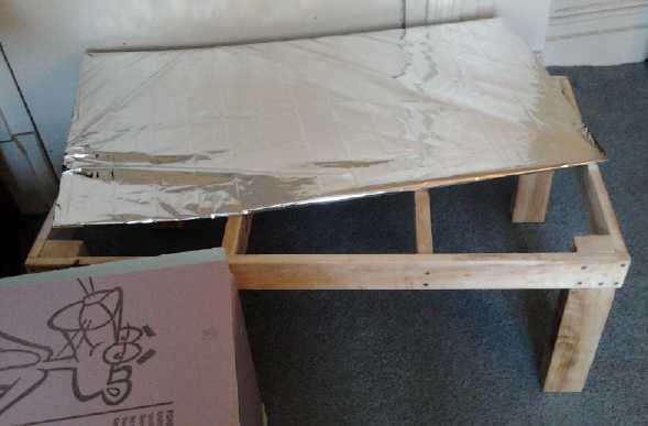 On the 13th (somewhat frustrated with progress on the
torque converter) I finally got back to work on the fridge: I made a
wooden stand for it. (figured lombardy poplar) I put an aluminized
"space blanket" around the "tabletop" (masonite) sheet, under the floor
of the fridge. With the fridge up on a stand,
it would be easier to put on the naugahyde, so I had put that off that
operation. And I still wasn't sure how to put on the space blankets and
still attach the fabric on top. Perhaps double sided tape was what was
needed? Finally I stapled it on, notwithstanding that staples barely
hold in styrofoam.
On the 13th (somewhat frustrated with progress on the
torque converter) I finally got back to work on the fridge: I made a
wooden stand for it. (figured lombardy poplar) I put an aluminized
"space blanket" around the "tabletop" (masonite) sheet, under the floor
of the fridge. With the fridge up on a stand,
it would be easier to put on the naugahyde, so I had put that off that
operation. And I still wasn't sure how to put on the space blankets and
still attach the fabric on top. Perhaps double sided tape was what was
needed? Finally I stapled it on, notwithstanding that staples barely
hold in styrofoam.
I got back to it again on the 24th, and lacking any other
inspiration, I stuck 3/4" cigar box nails through the naugahyde into
the foam to hold it on. It seemed to work okay and none are visible
with the lid shut. How durable they'll be is another matter.
The top cover is just 2" of extruded polystyrene. I'll probably glue a 1" sheet on the inside later to bring it up to 3".
(This will reduce the inside height by an inch.)
It's also a bit light so far to close firmly and could use magnetic catches or some more weight.
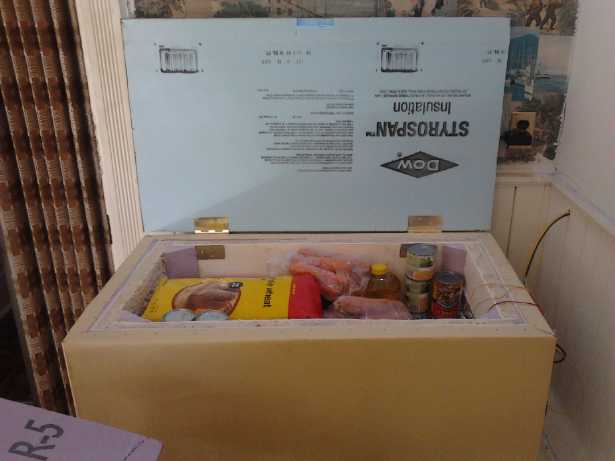
Long hinge bolts go through back wall from hinges outside to inner metal plates,
and from laminated plastic top through lid to new threaded holes in hinges.
A bit of the top was sliced to make the hinges, and the top, flush.
Bags of whole weat flour, tins, and a glut of carrots for juicing.
(A store near here has 50 pound bags of fat carrots or 5 pounds of skinny ones, and nothing between.)
At this point, the fridge is essentially finished except for a sound
muffling housing around the outer heatsink and fan and a few details -
and the "smart solar fridge control" plus "cooling ice tray". Under the
lid and maybe the inner walls could use some mac-tac or something, and
a square plastic funnel with a hose needs to be made to fit under
the inner heatsink to drain out defrost water. (A tray is collecting a
fair amount.) Presently, the overnight off time is plenty for a daily
defrosting.
On the wish list is an ice compartment or tray that will
hold more cold longer overnight as melting ice. Funny how a seemingly
simple project like a low voltage DC fridge can morf into a bunch more
projects: smart solar fridge control, design a melting ice compartment,
peltier heat pumps for "140% efficient" home or car heating, and a
whole new idea, magnetic heat pumping, with the promise of super energy
efficiency.
Peltier Fridge Cooling System
I wanted to try out a bigger heatsink inside the fridge
without a fan but didn't get to it. I also want to make some extra fridge cooling units
potentially to sell to people who want to make their own polystyrene fridge, with the "smart" solar fridge control. The main
ingredients are Peltier modules, fans (at least outside ones),
heatsinks, and a microcontroller based control setup.
The cool end of the fridge was getting down to about 6 or
7ºc. (Seemingly regardless of room temperature from 21 down to
about
16º, but very dependent on where the sensor was.) It didn't seem
to work quite as well after I attached the naugahyde, got the lid
hinged on and moved it to the kitchen. Huh? But I decided it
really needed a somewhat bigger Peltier unit,
or two of them, and I ordered an 8.5 amp Peltier module (the largest
economical one at Digikey) to replace the existing 6 amp unit.
After I
cut the 9 foot cord of skinny #16 or #18 wire down to 2 feet, the
voltage at the fridge was well over 12 volts instead of just 11, and
the current with
the new 8.5A Peltier module read 7.2 amps (up from 4.3/5.4 with the
old/new element and the long cord). The power cord... what an item for
a manufacturer to get cheap on! Maybe when I have "standard" plugs
designed and made, I'll just abandon their connector system and solder
a heavier power cord directly to the fridge PCB.
I couldn't find
extruded aluminum heatsinks that looked suitable for fridges, and the
prices for those I found were unworkable. So I guess I'll be creating
some arrangement
from aluminum sheet, chunks and maybe roof flashing.
The outer fan on
my present fridge is: Yate Loon Electronics, Y.L.Fan, D90SM-12, 12 V
(GP), .18 amps, about 3-5/8" square. The inner one is a 2-1/2" 'hamster
wheel' mini furnace blower: T & T, B9225L12S
ND1, 12 VDC, .18A.
I ordered 4 different square blow-through fans at Digikey
to try out. I hate fan noise and figured I'd probably pick the quietest
one(s)
rather than the best one(s). They were all much too loud, but I found
they could all be quieted by running them at lower voltages. The larger
8$ one was okay. The 5$ one seemed smoother than the two 3$ ones. I
picked it ("Q636-ND" per Digikey) for future fridges. The larger one is
maybe for the car or home heat pump.
When I put some resistors in series with the outer fan on
the fridge, it was quieter but the warmest temperature of the heatsink
rose from 38ºc to 42. I left it with an alligator clip jumpering
across the resistors.
On October first, the cooling ice melt idea, gradually
jelling became explicit. Melting ice absorbs a lot of heat before it'll
rise above zero degrees. Instead of a typical metal heatsink inside the
fridge, the cold side of the Peltier unit would be connected directly
to an enclosed metal tray of water. The water would cool and freeze
while the fridge was running, then gradually thaw overnight to keep the
fridge temperature from rising. The tray would have as many fins on the
sides as needed, and maybe a fan, to transfer the cold out to the
fridge. This is a lot cheaper than battery storage of cooling power as electricity - virtually free, in fact.
In
a test that day, a small open tray of water was placed in the fridge so
that the bottom of the heatsink (condensor, I guess is here the usual
name) was in the water. By evening, the water was mostly frozen. More
next month!
In considering the efficacy
of the Peltier cooling system,
I should figure that for about 8 months of the year, my kitchen is
cooler than is desirable, and heat is good. The inefficiency of the
Peltier as a cooler still makes it more than 100% efficient as a
heater, and of course I'm planning to make a Peltier heat pump to try
replacing an electric heater. So, what little heat the fridge makes for
house heating isn't
wasted for 2/3 of the year, and that should be factored in.
But it's also using about all the electricity collected by
one solar panel on a sunny day - 1/4 of the system and more when it's
cloudy. The magnetic cooling system would leave some of that panel for
other things.
Magnetic Heat Pumping
Slicing Gadolinium
I bought some new hacksaw blades and managed to cut a thin
slice off a piece of gadolinium, not in any brief time. Cutting steel
would probably have taken less time, or at any rate no more. However,
it was a good flat slice, weighing 4.3 grams. By contrast, the hacksaw
dust saved weighed 1.8 grams, so the slice (counting lost sawdust) was
about twice the thickness of the hacksaw kerf, measuring about
1.5mm/.06" thick. This is at least twice the thickness I want the
wafers to be, but it's about the best I can do. It's so hard I'm
reluctant to try running it through the jewelers rolling mill.
The 'wafer' didn't seem to heat and cool any more or any
faster. I was using an AD590 I.C. temperature sensor to read xxx.x
degrees K to 1/10th of a degree. I started to realize that the it
responded very slowly. Once the gadolinium changed temperature, that
had to filter through to the metal temperature sensor body and change
that, and then that had to filter through to the sensor semiconductor
itself, and then that would heat or cool the connection wires before a
stable reading was attained. This took a couple of minutes, during
which time, the Gd itself would be heading back towards room
temperature, especially with a thin wafer.
So I was reading about .3 or .4º change, but to
attain these readings, the Gd itself might be changing maybe .5, .6 or
.7º, or even more. On the other hand, it looked like each wafer
might only transfer .2 to .4 degrees in actual use for the same
reasons, which would mean a lot of stacks with a lot of boxes or layers
would be needed. 20º at 1/4 º/box = 80 layers. That would be
a lot of wafers, copper foil, plastic and effort. 80 boxes * 4
grams/box = 320 grams of gadolinium. And how much - or how little -
overall heating power in watts would be obtained with all that pricey
substance?
'Stardust' Design
I decided I'd try using a thin
layer of the Gd hacksaw dust instead of wafers. Provided it stays
reasonably spread out rather than clumping up in a corner, each flake
should contact the heatsinks, in total all across them, rather than
(theoretically) just at three points, and there'll be no need to make
the copper sheets and wafers flat flat flat for good thermal contact.
Nominally flat copper will do, and in very thin sheets. And it would
surely make maximum use of every milligram of gadolinium.
And perhaps to ensure the granules don't all collect in a
corner, I
should divide each box up into a bunch of mini boxes - or even into
little circles drilled or punched in a piece of plastic. If I could
find a thin molded plastic mesh with no gaps, each hole in the
mesh could be a little box with a copper top and bottom. (I do have a
molded plastic mesh - almost ideal, but it's too thick.)
So: Very thin sheets of copper with quite thin sheets of
plastic between them, full of holes, each hole filled 3/4 full of
gadolinium powder, all bolted together into a column of very thin
boxes. One might get 10 boxes in about .4" thickness, keeping the
substance pretty close to the supermagnets and needing only a few
columns. If there were holes punched in the copper where the bolts went
through, so they didn't touch the copper layers, they wouldn't transfer
(much) heat between the cold parts and the warm parts. For production,
the plastic pieces could be made on the 3D printer, and the holes in
the copper might be drilled on the CNC machine, or a bunch of sheets
could be screwed into a jig/drill template and all drilled at once.
Materials
This was starting
to sound much more makable! So I started getting materials. At Opus Art
Supplies I found thin copper sheet or foil, .15mm thick. This seemed
even thinner than was desirable, but then if each box was clamped
together with thick pieces top and bottom, all the thin copper and
flimsy plastic in the middle would have to lie flat. And the amount of
gadolinium powder wasn't going to fully change the temperature in one
pass anyway - at least not a thicker piece. It might as well be thin,
then!
At Michaels Crafts there was plastic mesh with little
boxes, about 3x3mm. It was thicker than I wanted, 1.2mm, and it looked
like each little box could use having its edges de-flashed. (Maybe I
could sand it thinner? Prospects seemed poor.) The 3D printer seems
like a promising solution for production.
These were the basic materials for the layers of each heat
pump column, other than the gadolinium powder to be added during
assembly. For the top and bottom I would use thicker copper that would
hold its flat shape. I already had some pieces of .8mm thick sheet. To
clamp the column together I would use two #6 flat head screws. The flat
heads wouldn't protrude towards the magnet rotor, allowing a small gap.
But on the bottom there was enough extra length to add nuts and bolt
the column to a mounting plate of some sort.
The column would be about 10mm tall. If I had .8mm thick
plastic boxes:
.8mm (top) + 10 x (.8 + .15 = .95)
= .8 + 9.5 = 10.3mm (we don't care how thick the bottom is)
and 10 boxes would fit. If each layer cooled .4ºc (hopefully) with
no thermal load, that'd be 4º, and 8 columns for a fridge would be
32º. Since the plastic was 1.2mm thick, adding the copper each
layer is 1.35mm, and only 7 layers will fit.
Well, if each layer cools more fewer total layers will be
needed. I decided I should look at the previous research again to see
how the magnetic field might be increased and deepened.
More Magnetism
 I went over the summary of magnetic
refrigeration paper to look for ways to get stronger magnetism. There
are ways with hallbach arrays to get a more intense field in a small
area, but none of them looked like they'd work for my design. Nor could
I put magnets above and below the stacks, since the design depended on
the magnets being above to lift the gadolinium into contact with the
upper heatsink.
I went over the summary of magnetic
refrigeration paper to look for ways to get stronger magnetism. There
are ways with hallbach arrays to get a more intense field in a small
area, but none of them looked like they'd work for my design. Nor could
I put magnets above and below the stacks, since the design depended on
the magnets being above to lift the gadolinium into contact with the
upper heatsink.
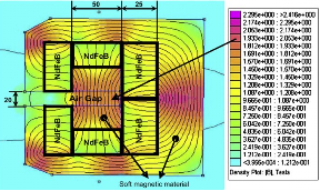
But one of the diagrams showed a concentration of flux in
an area behind the array between two side by side magnets (far right).
It seemed to have little to do with any of other four magnets. I
presumed one magnet faced each direction. If anything, in the diagram
the flux looked stronger than in the intended center area.
I put together four supermagnets - two deep of the
indicated arrangement. I had a hard time getting stable temperature
readings, with sun shining on the workbench and moving across. (At one
point the Gd heated .9º. Seemed fabulous... but it only cooled
.2º when the magnet was removed.) But I soon realized it didn't
matter: I could feel that the new arrangement was much more strongly
attracted to the chunk of gadolinium than the previous three half
supermagnets stack, and far more strongly than any single magnet. For
the actual rotor I'll use 3 deep - 6 magnets total. The extra flux
should save making a stack of boxes or two.
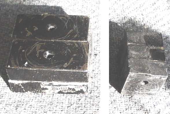
The taker arrangement (L) being derived from the back side of a
Hallbach array,
I think I'll just call it a "haul back" array.
The magnets will travel L-R, with the high flux join running along the
stacks.
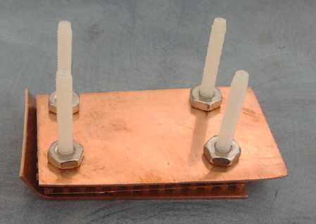
The interior copper sheets are thin - foil - while the outer ones are thick for stiffness.
On the 15th I put together a copper plate stack with just
two layers, complete with plastic mesh for boxes, .5 g of gadolinium
powder per layer, and plastic (thermally insulating) screws to clamp it
together. I ran my "hall-back" array of magnets back and forth past it.
The amount of attraction seemed about right, but I found only small
temperature rises - no cooling. Then I realized that the magnets would
generate electricity into the copper plates, heating them. Oops! The
theory of operation appeared to have a flaw.
There are remedies, but I didn't have time to get back to the project.
http://www.TurquoiseEnergy.com
Victoria BC