Turquoise
Energy Ltd. News #57
Victoria BC
Copyright 2012 Craig Carmichael - November 3rd, 2012
www.TurquoiseEnergy.com
= www.ElectricHubcap.com
= www.ElectricWeel.com = www.MushroomOutboard.com
Features: 12V Solar Fridge freezes ice during day; melting ice keeps it cool at night - reduces battery requirements - Magnet Machine Experiments - CNC Farming
Month In Brief (Summaries)
- 3D printer: Wow, it works!
Designed and made lots of stuff. - CAT Standard 12VDC plugs &
sockets, my "Green Drinks" video clip: http://mobilizinghope.com/2012/10/10/craig-carmichael-inventor/ - etc.
In Passing (Miscellaneous topics
and editorial comments)
-
Heat:
Units of Confusion - Geothermal green energy can't get investment: need
Dept. of Progress - Russian
food self sufficiency sponsored by government - Petroleum Dependency:
Electrify the
Railroads! - Electric & CNC Farming Machines - Electric
Fishing Boats - How much food reserve to have? - Visionary inventor
Ovshinsky dies at age 89.
Electric Hubcap System
* Sprint car: Flat Belt Drive and printed plastic flat belt pulleys
* Mushroom Outboard: Plastic Printed Foot?
* Mushroom Outboard: More efficient Propeller?
Planetary Gear Torque Converter
Project
* Plate to hold bearing to hold planets assembly centered (then rain, rain, rain :(
Mushroom Outboard Motor Project
* More Efficient Propeller
Solar Electricity Project
* Solar 12 VDC house wiring: Main circuits and distribution panel
* CAT 12 volt DC sockets, Plugs, wall plates
Superinsulated 12V Thermoelectric Fridge &
Freezer - Peltier Module Heat Pumping
* Melting Ice Chest + smart control keeps fridge cold overnight: uses power mostly in daytime
Turquoise Battery Project
* Printing Porous Electrode Pockets, Zinc
Magnetic Motion Machine Project
* 3D printed parts help do prototype
No Project Reports on: Weel
motor, DSSC
solar cells, LED Lighting, Pulsejet steel
plate cutter, Magnetic Heat Pumping
Newsletters
Index/Highlights: http://www.TurquoiseEnergy.com/news/index.html
Construction Manuals and information:
-
Electric Hubcap Motor - Turquoise Motor
Controller - 36 Volt Electric
Fan-Heater
- Nanocrystalline glaze to enhance Solar
Cell performance - Ersatz 'powder coating' home process for
protecting/painting metal
Products Catalog:
- Electric Hubcap Motor Kit
- Sodium Sulfate - Lead-Acid battery longevity/renewal
- NiMH Handy Battery Sticks, Dry Cells
- LED Light Fixtures
Motor Building
Workshops
...all at: http://www.TurquoiseEnergy.com/
(orders: e-mail craig@saers.com)
October in Brief
On the 3rd I finished
wiring, testing and adjusting the 3D printer and tried it out, with the
netbook computer and Pronterface.
There
was no smoke or flame when I plugged it in, and everything worked the
way it was supposed to. Wow! I downloaded a sample 3D STL file and
printed it in PLA plastic.
On the 4th and 5th I downloaded
OpenSCad, and designed a few
items and printed them: a sample ring, some
battery
electrode pockets of increasingly workable design, a trial mini model
of an LED globe or mushroom light fixture base, and some increasingly
effective attempts to make a CAT standard 12VDC socket for Pico "universal"
.205 inch blade sockets.
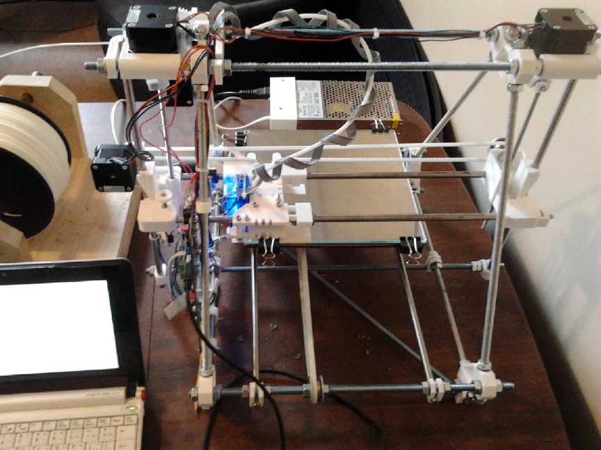 ReprapPro
[.com]
Mendel 3D Printer
(200x200x140mm heated glass bed build space, USB interface or standalone printing with mini SD card)
Left: Netbook to run it (Ubuntu - OpenSCad, Pronterface ...all freeware), spool of ABS plastic filament
Behind: power supply (12VDC). Printer's electronics board is edge-on at front-left.
 Having accumulated so many manufacturing plans for 3D
printing, much of the month then became devoted to designing and
printing various plastic objects wanted for several projects. The
weather split the month 1/2 way, suddenly going from sunny and warm to
rainy and cold. Just about the time I had bought and printed most of what I
needed for the Sprint car/torque converter/drivetrain project, it became much nicer to do indoor
things.
Having accumulated so many manufacturing plans for 3D
printing, much of the month then became devoted to designing and
printing various plastic objects wanted for several projects. The
weather split the month 1/2 way, suddenly going from sunny and warm to
rainy and cold. Just about the time I had bought and printed most of what I
needed for the Sprint car/torque converter/drivetrain project, it became much nicer to do indoor
things.
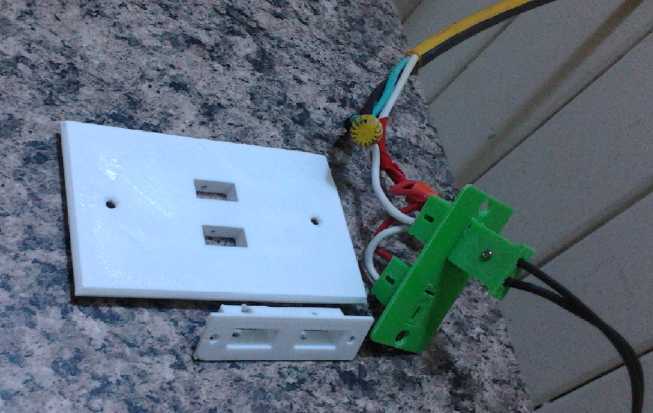
I printed
cover plates for panels and for electrical boxes to
hold the CAT sockets, CAT plugs to match the sockets, a 4 pocket set of
electrode
plates (to match the 68mm width of available sheet zinc 'roofing'
strips), glue-on caps for
those plates, 7" pulleys for a flat belt to fit the Sprint car
differential and a piece to hold a center bearing for the planets assembly, and a 3.25" LED
light/lamp base.
Porous plastic electrode pocket assemblies ready to add chemicals and glue into a battery cell
(except the positive current collector is only a sample and a filler/air block cap is still needed)
 I
started in on doing a series of short videos on battery making. I'm
sure a video would bring the whole thing to life in people's minds. But
I won't complete it until I have usable, working batteries myself.
I
started in on doing a series of short videos on battery making. I'm
sure a video would bring the whole thing to life in people's minds. But
I won't complete it until I have usable, working batteries myself.
Towards the end of the month I started designing a battery
holder for 10 D cells, to make 12V/10AH/30A long life, maintenance free
NiMH batteries, about 1.5" x 5" x 7". The ventilated design will be stackable to build
higher amp-hours or higher voltage. Thus for example one could have a
30AH NiMH car battery in 4.5 x 5 x 7 inches. Tentatively I hope to
manufacture these cases and sell them for about 10$ each.
Geometric object
designing with OpenSCad is pretty straightforward, tho a bit like
programming in C - overly structured and with lots of "{", ";", empty "()" and stuff. (More under "Turquoise Battery Project".)
It's a great relief to have the machine up and running
- and fascinating to watch it printing. If I'd
bought one assembled instead of the kit I might have had it a couple of
months sooner, but evidently I now have one of
the best current 3D desktop printers, and I saved hundreds of dollars.
I'm very glad I got the larger Mendel rather than the smaller Huxley. I
remember being on the site last spring to order, thinking mainly of
making porous battery electrodes and wondering whether to spring the
extra 100$. Even afterwards I couldn't remember if I had or not. Thankfully I did. The smaller size couldn't make some
of the things I've already made, or the battery case.
The
print head really zips around the bed, but
it takes quite a while to build up any substantial object by
squirting a fine bead of melted plastic out a tiny nozzle. A little CAT plug
takes 5 or 6 minutes. A 7" x 1-1/4" pulley takes 5 or 6 hours. I can
see wanting two or even several of them going at once if there are
customers waiting for
orders. Their total price would still be a very low cost for entry level
manufacturing.
 I went to get pins for the CAT socket plugs and ran into a
small snag: Pico doesn't make them - only the sockets! Apparently they make
that size socket solely for AT fuse sockets.
I went to get pins for the CAT socket plugs and ran into a
small snag: Pico doesn't make them - only the sockets! Apparently they make
that size socket solely for AT fuse sockets.
I started redesigning the system for the larger but more
common .33" x .250" x .030" blades and sockets, but when I printed a
plug, I didn't much like it. It seemed needlessly large, and Pico's
blades didn't lend themselves to being put in a shell anyway - they
should be a little longer to reach through the plastic front faces of
both the socket and the plug, about 2mm extra. I decided to stick with the
".205 inch" size. Blades are easy to make out of .025" sheet metal.
Manufacturers like Pico can catch up - probably with whole plugs and
sockets - when people are asking for them and they
realize what they're being used for.
I talked to a few people about the CAT plugs & sockets at Green Drinks on the 10th and ended up doing a little video blurb on them. http://mobilizinghope.com/2012/10/10/craig-carmichael-inventor/
. I see I showed the sockets but neglected to plug in a plug. After
doing some wiring with them, each time, I found my brain started
automatically going to the crossways blade as positive, when I had
decided that one would be the negative. I figured others would do the
same, so I reversed them. That'll also make
for slightly more compact 24 volt plugs and sockets, which I plan to do later, with perhaps 13mm blade center spacing:
- | ... 12V
- | ... 24V
- | | ... 12/24V
Official CAT Standard specs are in the "Solar
Electricity Project" section, as is more info on the 12VDC "Main Panel"
I've been configuring and wiring up:
12 Volt Main Panel
I turned for a short time to a project I've neglected for
the better part of a year: setting up to manufacture LED globe lights.
With the 3D printer I hoped to make some custom shapes for light bases
with mountings & vent holes built in, the simple PCB artwork needed
inside the lights, 12 VDC plugs and receptacles per my new "CAT"
standard that I hope everyone will adopt, CAT to "wall
wart" 120V power adapter socket cords, and car cigarette lighter to CAT
receptacle adapters. The lights would then be ready for 12 or 120 volt
usage with plugs for most common situations. After some earlier test
version bases, on the 17th I tried printing out globe bases for PCV
pipe lamps.
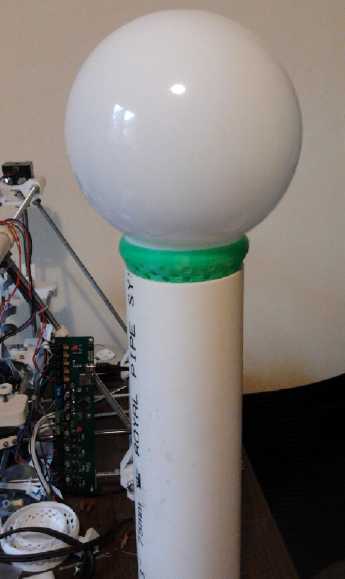
3D Printed LED fixture or lamp base [green]
Solar Fridge ice tray uncovered. The bottom bolts thermally connect the Peltier cold
side to the water via aluminum plates & pan. The water gets partly frozen during
the day while the sun powers the circuits, then the melting ice keeps the fridge
cool overnight with little (or potentially no) battery power.
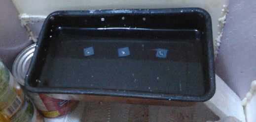 The 12 VDC superinsulated Peltier element fridge
design
got a boost with the idea of freezing a tray of ice during the day,
which would slowly melt, keeping the fridge cool overnight until the
solar collector(s) came on again in the morning. I put holes through
the bottom of the
pan to a thick plate to get better heat transfer, and over a day the fridge would
freeze 1/2 the
water or more in a pan holding 1 litre. Cold transfer from the tray to the fridge is
adjusted simply by how much foam surrounds the ice tray. More foam
allows the ice to last more hours, and with winter drawing on and
sunlight reduced to about 8 hours a day, to have it work "perfectly"
would require the ice to last at least 16 hours. In practice it seems
to need to run about 14 hours, using about 39KWH of mostly solar
electricity in a month.
The 12 VDC superinsulated Peltier element fridge
design
got a boost with the idea of freezing a tray of ice during the day,
which would slowly melt, keeping the fridge cool overnight until the
solar collector(s) came on again in the morning. I put holes through
the bottom of the
pan to a thick plate to get better heat transfer, and over a day the fridge would
freeze 1/2 the
water or more in a pan holding 1 litre. Cold transfer from the tray to the fridge is
adjusted simply by how much foam surrounds the ice tray. More foam
allows the ice to last more hours, and with winter drawing on and
sunlight reduced to about 8 hours a day, to have it work "perfectly"
would require the ice to last at least 16 hours. In practice it seems
to need to run about 14 hours, using about 39KWH of mostly solar
electricity in a month.
The Superinsulated 12VDC Peltier Cooled fridge is now about finished
except for the "Smart Solar Fridge Control".
Manually controling the fridge is wearing thin. It still
needs that 'smart solar fridge control'. I bought two
microcontrollers and development systems to try out for that: AT-Mega328 (Arduino
development kit) and TI's MSP430 (TI Launchpad development kit). They'll
be useful for other controls as well, eg, for the Peltier heat pump,
which I started putting together. The AT-Mega is currently popular (eg,
it's the 3D printer's brain) and far better designed than the old PIC chips. The
newer MSP430 has 16 bit general purpose
registers (PDP-11!) and looks like perhaps the nicer to program, and it's
cheapest... but of course
it's one thing to buy the pieces - more time consuming to become
familiar with them and start programming them, and then install them in
a circuit on a
board with all the parts. I'd rather be doing ARM chips, an excellent
'open source' 32 bit architecture that has been licensed to several
companies. But it's a bit overkill for a fridge. It would add a few
dollars to the cost and (worse) the surface mount chips would make the circuit board too complex for my simple PCB making idea.
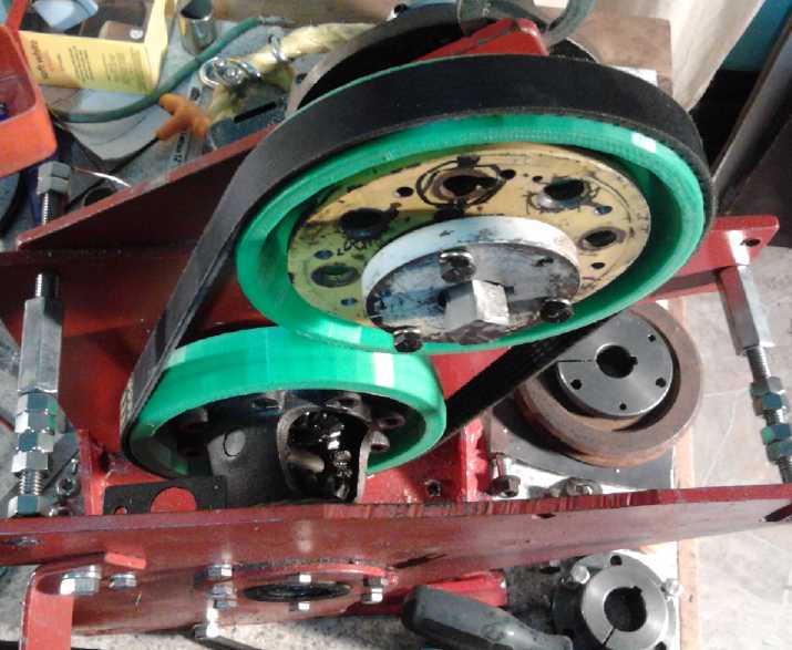 For the Sprint car, I started thinking: A flat belt will
slip on a small pulley, hence V-belts, toothed belts and other types.
But I was planning to use two large pulleys, so there'd be sufficient
grip surface on both.
I found one in my exact required length at Key2Parts.
It was only 20mm wide, but tough looking - and it was only 30$. Another
advantage of the flat belt is that the pulleys are 'barrel'
shaped and the belt centers itself. It can be slipped on from the side
with the pulley distance already adjusted.
For the Sprint car, I started thinking: A flat belt will
slip on a small pulley, hence V-belts, toothed belts and other types.
But I was planning to use two large pulleys, so there'd be sufficient
grip surface on both.
I found one in my exact required length at Key2Parts.
It was only 20mm wide, but tough looking - and it was only 30$. Another
advantage of the flat belt is that the pulleys are 'barrel'
shaped and the belt centers itself. It can be slipped on from the side
with the pulley distance already adjusted.
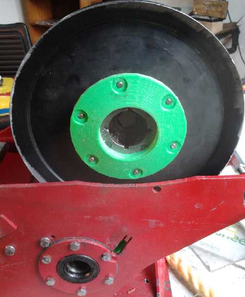
I decided to try this belt with two new 7" 3D printed
ABS plastic pulleys, each made to fit where it was going. If the pulley rim
surface wears out too quickly, I'll have to make some sort of aluminum
outer rim.
Along with that I beefed up the original
planetary gear, with a
plastic plate to center a single bearing on the motor shaft to help hold the
planets assembly centered. Perhaps that would eliminate the need to
make the plastic planetary gear with its dubious strength and
durability. In theory the existing gear set should have plenty of
torque if everything was on axis and supported.
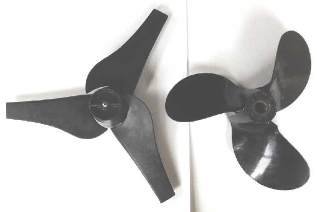
For the Mushroom Outboard, I explored propeller designs.
It seems boat and ship propellers were simply developed from posthole
augers, and that something more like an airplane or windplant
propeller, with a larger diameter, would be more efficient. I was given
just such a 12" plastic prop from a hand held scuba propulsion unit. It
seems ideal, and I hope tocast the blades in metal for a better outboard prop.
In writing "in Passing", I conceived of a whole new way to farm: the CNC Farming Machine! Read about it below.
I didn't get to doing anything with magnetic heat pumping,
except to order a whole kilogram of gadolinium, which it turned out had
dropped in price at HEFA, listing for 325$ instead of 450$(?) a couple of months ago.
In Passing
Incidental news, editorial opinions
Heating & Cooling: Confusing terms
"Murphy's Law" originally stated in about 1970 (among many other things)
that "Values shall be presented in the least usable, most obscure units: For example, a velocity might be given as 'Furlongs per
Fortnight'."
Some misleading units are US vs Imperial gallons, or
Avoirdupois(sp?) ounces versus Trojan ounces. (Troy fell. Its legacy
lives on, perhaps propagated by unscrupulous buyers of gold from
miners... "No, that's not an ounce! To get full price you need a..
a.. "Troy" ounce, yeh, yeh, that's the ticket, a "Troy" ounce!")
In refrigeration and heat pumping we see ratings of "tons
of capacity". This makes it almost impossible to compare with a simple
electric baseboard heater rated in watts. It turns out that a "ton" is
the amount of energy needed to freeze 2000 pounds of water to ice
overnight (or something like that). In equally obscure units, that turns out to be 12000
BTU/hour. BTUs evidently translate to .2931 watts/hour, so... if I have it
right... a "ton" capacity is about 3.5 KW.
Geothermal Energy
On the 25th I went to a Greentech Exchange seminar where the topic
was geothermal energy. While Canada has some ground source heat pumps
here and there, we're the only large country that's never made a
geothermal electric generating plant. It was about the same sad tale as for
the wave power, or tidal: BC Hydro is prohibited
by the government from investing in anything but river hydro, so people
are forced to form "IPP" (independent power producer) companies and beg for
funding from the likes of "angel investors" and "venture capital"
outfits, who prefer sure,
proven things. And for a high returns but capital intensive project
like digging a very deep
well to reach water above boiling point, venture investment isn't
enough.
It's the same thing as the
Site C Dam: if the BC premier says "let's do it", it gets done. Until
then, it doesn't. Imagine some startup "IPP" company looking for
venture capital to do something like Site C - Hah! But politicans feel
unqualified to judge the merits of such things. They couldn't be
bothered with "low budget" proposals, yet they don't authorise
subordinates who they place in positions of judgement to allocate
even small research or development funds. (For example, the BC government has
officials in charge of ocean energy, but they have no power to say,
"Yes we like that design best, let's figure out a budget and see if we
can get it going." What, then, is the point of having them?) And they
are too much afraid political capital
will be made of any 'failure', 'lagging schedule' or higher than
expected cost if any new plan with a higher budget is attempted. Two
times I can think of that heads of state authorized high budget
experimental projects in peacetime were Laurier for the Avro Arrow and
Kennedy for the Apollo space program. Those were a long time ago.
Again I commend the Department of Progress as an
essential arm of government. Since it's the department's business to
try out new things as investments in the future, poor results of an individual project wouldn't
reflect much on the government of the day, and it would be hard to
point any fingers at the politicians when the decisions are departmental. Overall,
such a department would by trying a number of things at any given time,
and some of them would work and pay unimagined dividends that dwarf the
losses from the failures.
Food Local Sustainability
I ran across a news article saying that Russians
currently grow much of their own food (nearly all their potatoes) in
home gardens and small farm plots of 2 to 6 acres. All in Russia's short northern growing seasons. The Russian
government has been encouraging this with free - including tax free - plots
of land for the purpose since 2003. (Rah for Putin!) Russia of course has already had its own
collapse with empty grocery stores in the late 1980s, and perhaps they learned
the value of local sustainability from that. I can't help but think Russians will weather
the coming financial collapse much better than North Americans, where
most of the food is grown on huge "agribiz" farms and few people grow
food gardens - and where lack of petroleum will mean lack of means to grow and to transport food.
As elsewhere, there are various local farms and sustainable food growing
movements on Vancouver Island as well as home gardens, and all of them are likely to take on a sudden importance.
One rumored source apparently connected to 'big oil' says
there'll be no shortage of food in the stores, but inflation
will make what's there unaffordable to many. But history shows that
when inflation reaches a critical point, people don't trust the money
any more or try to save any. The crisis finally becomes a sudden collapse of confidence. Hyperinflation takes hold and everyone
rushes to the stores to dump
their cash for food (or almost anything useful), since they know it will buy less tomorrow than today. This strips the grocery
shelves bare in hours.
But how much food is it useful to have on hand? Most
nutritional items go stale or bad - some sooner, some eventually. The
following sentences may provide some sort of rough guide.
A couple of people have estimated they eat 200 pounds of
grain in a year - rice, wheat (including bread), oatmeal... Someone on
youtube suggested one should have 6 months of food on hand in plastic
or metal containers. That's 100 pounds of grains with other things to
go with them per person. But the need will vary by location. Ideally I'd prefer
to have enough on hand to last until the next fall harvest for the
worst case: that it becomes necessary to grow much of one's own food
for a year or two.
A great crisis, however unwelcome and potentially dangerous, may
offer fantastic opportunities for individuals to make a difference, to contribute
to the future of the world. Winston Churchill wrote during world war 2
something to the effect that people shouldn't consider the years of the war
as lost years - that they would look back on them as the most exciting
period of their lives.
And now we're racing headlong into a different sort of world crisis.
(If you don't think so, look up "financial collapse" on youtube and
watch a few videos. Find out how our world's financial system "works"
and why it's a cancerous, dead-end system that has grown to dwarf and
finally to strangle the economy it's supposed to serve. ...and explore
other major stories that the mainstream "news" isn't permitted to
cover.) The
coming chaotic years and following decades will be an exciting, fascinating time
to be alive. They should see a
beginning - if only a beginning - of real progress towards socially
sustainable institutions, which all the other forms of sustainability
will flow from.
Petroleum Dependency - Electrify the railroads!
On the subject of petroleum, the California gasoline rationing and price spikes, tho
apparently caused by unusual regional events, shows how vulnerable the whole
transportation house of cards is to petroleum shortage. A variety of electric cars are finally starting to be made and sold ( http://electricandhybridcars.com/
). This is great (tho they're probably too little too late for large
scale immediate value), but it's only one aspect of the problem.
As the crisis
looms, the elementary step that I keep thinking would cushion the blow and probably save many
lives is: Electrify the Railroads! If
Europe can be almost all electric rail - and Japan -
and the Trans Siberian Railway - just what is our problem here? The
European electric rail system was ironically based on an early US
electric railroad, which was financially sabotaged by the Rockefellers
as it was being built, and never completed. But it hauled freight
across the rockies electrically for some decades, with the trains going down powering the
ones going up by regen braking. (At the same time, GM and affiliates
were tearing up the USA's beloved electric trolley systems, city after
city, with impunity. Some of these lines also ran between cities, at good speeds.)
Nothing is easier to electrify than railroads since fixed
overhead lines provide power without a need for electricity storage.
(Tho perhaps my idea for shorter range 'ULRT' ("Ultra Light Rail
Transport") for
Vancouver Island on the existing E & N rails could operate partly
on batteries, with only more strategic sections near existing power
lines having overhead wire for recharging them on the go. This could
reduce the capital cost.)
Electric & Computerized Farm Machinery
It seems to me also very important to start electrifying
farm machinery, especially with no workhorses around any
more. Otherwise, if farmers can't get fuel, there may not be a lot of food grown to transport. This
isn't as hard as electrifying cars since tractors on a field don't have
too far to go for recharging any time they're running low. The work may
be hampered by a frequent charging requirement, but it's doable --
nothing like trying to farm by hand.
But we could actually advance the whole way we farm, with CNC Farming.
A
tool carriage traverses back and forth under a truss bridge that spans
a field, having one rail on each side. This carries all the tools and
supplies and brings them
to any point on the field from above, like an X Y plotter or CNC
machine, to perform virtually every operation of farming, with low,
electric, energy use. ...It rototills - it plants - it waters - it weeds
- it harvests! (But wait, there's more! ....deer and raccoon spraying attachment at no extra charge!) There'd be no vehicle tracks left in the growing
area, and in some areas fields could be worked earlier in the spring when it's still too soggy for a tractor.
Different crops could easily be planted even in the same
field with different programming for each, avoiding crop monoculture.
Perhaps small rigs for narrow fields (or even for home vegetable gardens)
would be cheaper than a tractor. Special tracks at one end of each
field strip could move the rig sideways to the next field over.
I already want one just for my own garden! This
would seem to have great potential for a manufacturing enterprise.
The average age of
farmers in the USA is 58. An automated approach could appeal to a whole
new generation of growers who don't seem very interested in driving
belching tractors and combines. Such equipment, making optimal and
flexible use of farmland, might also make small farming more
attractive, to gradually displace mega-farming and giant agribiz.
Electric Fishing Boats
And if we want food from the sea, we should certainly be
working towards electrifying fishing boats. These at least have a
considerable capacity for holding batteries. Of course, my Mushroom
Outboard should work toward this end (must get on with it!), and more generally my
highly efficient Hubcap and Weel motors can be used for many mobile
electric purposes.
Stan Ovshinsky dies at 89
Self taught inventor
Stan Ovshinsky died on October 19th. On reading his obit (link below) I
discovered that he not only invented the practical nickel-metal
hydride battery that made the GM EV-1 and hybrid cars so good, but also
the 'glass transistors' that make our flat LCD video and TV screens
possible. Otherwise we might still be using picture tube displays. Also, in common with many inventors, he was an
idealistic visionary: "...his work was inspired by a vision of humanity freed of resource wars and climate change."
The potentially leading role of his NiMH batteries towards these ends was
squashed, except as small dry cells, by the gangsters who have run our
economy until now. They were economical,
long lived and relatively lightweight. They would have soon replaced lead-acid and
would have been available years before the more costly lithium types started coming on the market.
Ovshinsky's business abilities have been criticized, but for an
inventor to get as far as he did commercializing a product like
batteries that would upset "big oil's" transportation monopoly is in
fact remarkable. It seems a pity transportation and solar home size
NiMH's didn't make it into the big box
stores before being stomped out. On the other hand, MnMn is much better
and cheaper, and 3D printers will help ensure they become available. I
wouldn't have taken the time and trouble to work out a new battery chemistry and construction if
big NiMH's had been available... "All things work together for progress!"
http://www.globalpost.com/dispatch/news/science/121018/stanford-ovshinsky-battery-inventions-smartphones-toyota-prius-lcd-tvs-inventor-video
Electric
Hubcap Motor System
Sprint Car Drive Belt and Pulleys
I looked high and
low for toothed belts and pulleys, then I decided maybe I should try a
flat belt. Shouldn't that be the most efficient of all?
The reason for poly-V-belts and toothed belts is that a flat belt will
slip on a small pulley. But I wanted to let the torque converter do the
speed reduction and use two large pulleys for the final drive - so I
didn't
need a toothed belt! I phoned a
'farm equipment' company -- no, but he was sure Lordco would have them.
I
went to Lordco and they didn't. Since I was there I thought I might as
well try next
door at Key2Parts, and to my great surprise, they had a 38" flat belt
(my length) in stock - "Goodyear Gatorback 4060380 6PK965".
It was only 20mm wide (I was ideally hoping for 30+), but thick
and very tough looking, and it was the first
appropriate belt I'd even laid eyes on, so I bought it. And it was
only 30$ instead of 100 or more for a toothed one. (It had an odd
pattern on the inside, which I figured was texture for grip, but I
noticed later that the package said "Poly-V belt". It's still just as
usable for a flat belt.)
I keep hearing how strong newer belts are. Hanging from
it and yanking it didn't seem to phase it, so
obviously it could take 200+ pounds easily. I figured it would probably take 700
okay, which will be the maximum assuming 200 foot-pounds of
torque and a 7" diameter (3.5" radius) pulley. (200 FP * 12/3.5 = 686)
Besides the low price, an
advantage of the flat belt is that the pulleys are barrel shaped and
the belt centers itself as it turns. It can be slipped on from the side
with the
pulley distance already adjusted to get the desired tension. And as
long as it doesn't slip, it's tight enough, where the toothed belt has
to be 'just right' to mesh well and minimize wear.
Later in the month I started to consider that a 30mm
(1-1/4") wide belt would be better - stronger and with more gripping
surface. By then I had
printed the pulleys, and I'd made them wide enough for it. Finding the belt again becomes the problem.
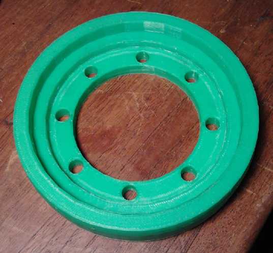 Actually printing the pulleys proved
unexpectedly challenging. After designing the part on the 10th, it took over an hour for the printer software
to process the data and turn it into G-Code, then 5 hours to print. I
aborted the first print after two layers of the 77 layer total (yet almost an hour) to check the
fit on the differential, and found it did indeed need small but crucial
adjustments. The printing of the "real" one messed up after 3 hours.
The unit had been trying to feed the ABS filament faster than it would
melt, and finally it stopped moving with a chunk out of the side facing
the drive gear. It didn't miss a lot initially, but some subsequent strands tried
to print in the air just above the missing material, and everything
turned into a mess, so I stopped it.
Actually printing the pulleys proved
unexpectedly challenging. After designing the part on the 10th, it took over an hour for the printer software
to process the data and turn it into G-Code, then 5 hours to print. I
aborted the first print after two layers of the 77 layer total (yet almost an hour) to check the
fit on the differential, and found it did indeed need small but crucial
adjustments. The printing of the "real" one messed up after 3 hours.
The unit had been trying to feed the ABS filament faster than it would
melt, and finally it stopped moving with a chunk out of the side facing
the drive gear. It didn't miss a lot initially, but some subsequent strands tried
to print in the air just above the missing material, and everything
turned into a mess, so I stopped it.
I had noticed that the printer kept setting the extruder
to 200ºc when it started to print, even after being manually
commanded to 250. 200 is to low for printing ABS, and I noticed I could
pull strands off the edges of small things I had printed - they weren't properly melted together. I changed settings
everywhere I could find, but it always went to 200º.
On the 17th I discovered that the 200º was being put
in in two places near the top of each g-code file, and that editing
both numbers (to "S250") and saving the modified file would
change the temperature. I also found that putting a few pieces of paper
on the bed while it was warming up allowed it to get up towards its
110º setpoint. It wouldn't hit 100 without it. After printing a
couple of small things in ABS with good results, I decided to have
another go at the pulley. It came out well except the critical fit over
the outside of the flange was slightly small. (As it didn't reach this
part until the pulley was around 2/3 printed, there was little point
doing another partial print test.) I scraped out a little plastic all
the way around with a chisel, and after a couple of goes of that, it went on.
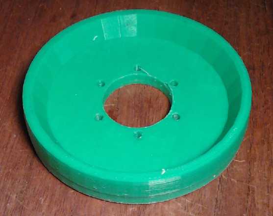 The other pulley being the same except for the center
mounting area, I designed it that evening after a couple of guests, who
took pictures and video of the printer in action, had left and the
first one was done. It too was a bit small in the center and needed quite a lot of scraping out of material.
The other pulley being the same except for the center
mounting area, I designed it that evening after a couple of guests, who
took pictures and video of the printer in action, had left and the
first one was done. It too was a bit small in the center and needed quite a lot of scraping out of material.
I have no idea how long the plastic pulleys will last, or
even if they'll work at all. My guests and I discussed the idea of
making a plastic part and using it for lost wax ("lost plastic") casting,
perhaps (in my view) of zinc-aluminum alloy ("pot metal") or aluminum.
Or perhaps an outer rim of aluminum might be the load bearing "tire" on
an otherwise plastic pulley. But trying it out by hand, trying to force
the pulleys to turn opposing directions using a wrench and a
screwdriver to pry them, I couldn't get the belt to slip and nothing broke.
Planetary Gear Torque
Converter (PGTC) Project
It's getting harder to
distinguish between the converter and other parts of the Sprint car
transmission as being separate projects. But the 1 to 1 ratio of the
belt drive to the differential is reasonable only because all of the
required speed reduction/torque increase should be readily attainable
in the converter.
 I figured I could put a plate on the planets assembly
that would hold a bearing
and hence hold the assembly more or less centered on the motor shaft.
(Two bearings would be the proper way, but there's no room.) That
should go a
long way towards preventing friction and binding owing to misalignments
caused by off-center forces (mainly the slip clutch rope). It seemed
well worth trying before replacing the metal planetary gear with
a large plastic one. That would necessitate further changes of
configuration, and it just might not be strong enough.
I figured I could put a plate on the planets assembly
that would hold a bearing
and hence hold the assembly more or less centered on the motor shaft.
(Two bearings would be the proper way, but there's no room.) That
should go a
long way towards preventing friction and binding owing to misalignments
caused by off-center forces (mainly the slip clutch rope). It seemed
well worth trying before replacing the metal planetary gear with
a large plastic one. That would necessitate further changes of
configuration, and it just might not be strong enough.
On the 21st I realized that a two piece trailer bearing
wouldn't be suitable, and I thought about where to get a 1-1/16" I.D.
bearing. In the end I didn't find one, but I found a 1-1/8" and made a
shim. I 3D printed the plate from plastic. It was hard to push it onto
the bolts, and since it can't come off once installed, nuts seemed
superfluous.
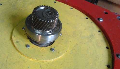
New bearing mounted behind the sun gear on the motor shaft.
Above-right: plastic flange fits closely around bearing to center planets assembly...
at least, to center one side of it on the motor shaft... but not on the output shaft/ring gear.
The one piece remaining to work out before trying the unit
in the car is the balanced clutch rope assembly. I didn't see a simple way to do it, the weather turned
cold and wet and then somehow I got onto other things.
Mushroom Outboard (Outboard Motor from Scratch) Project
If I haven't had time to
work on this so far, it's not without giving it a few thoughts now and then. It
occurred to me that the most troublesome piece, the foot, might be made
of ABS plastic: a plumbing pipe main piece plus some fitting pieces done on the 3D printer, to be glued
together and to the leg with methylene chloride.
 And
while I was thinking about that, the idea that a
propeller from a gas outboard, typically of about 9" diameter for a
small outboard, might not be optimum for efficiency came up on
"Electric Boats" list. It turned
out Ray Electric Outboards has their own 12.5" props cast 'for better
efficiency'. I thought I might order one of those and give it a try,
but right after I mentioned that, someone locally gave me a 12"
propeller - a handheld scuba propulsion unit missing some parts. I
removed the prop. It looked quite different from most outboard props.
Much more like [the mirror image of] a windplant prop. It was also a
substantially shallower pitch. It
appeared to be variable pitch with separately molded blades, but the
pitch was internally fixed with no adjustment mechanism - just a bit of
play.
And
while I was thinking about that, the idea that a
propeller from a gas outboard, typically of about 9" diameter for a
small outboard, might not be optimum for efficiency came up on
"Electric Boats" list. It turned
out Ray Electric Outboards has their own 12.5" props cast 'for better
efficiency'. I thought I might order one of those and give it a try,
but right after I mentioned that, someone locally gave me a 12"
propeller - a handheld scuba propulsion unit missing some parts. I
removed the prop. It looked quite different from most outboard props.
Much more like [the mirror image of] a windplant prop. It was also a
substantially shallower pitch. It
appeared to be variable pitch with separately molded blades, but the
pitch was internally fixed with no adjustment mechanism - just a bit of
play.
The pitch seemed rather shallow to get a small boat moving
too fast with 2000 RPM. I might be trading the gear reduction of the Honda conversion
for pitch reduction. On the other hand, it should push a larger boat
quite nicely at a lower speed. That's what the most customers would
want. On that note, it also passed by on the list that the optimum
efficiency (for a 'typical' prop) was with a forward push of 1.5 times the diameter per
rotation - a steep pitch. But then I looked up a link and found:
"HISTORY OF [boat] PROPELLERS - The modern day propeller was designed by accident. Trials of a
screw, much like a post hole auger, had been somewhat dismal until one
day the auger broke off close to its base and had much more power. Such
is the origins of our modern day propeller. What most people don’t know
is that propeller technology has kept evolving with the greatest
strides in efficiency in the last 10 years. Today’s propellers are far
more efficient than their historical counterparts."
It doesn't sound like boat propellers, which were after
all the first propellers, underwent the same sort of critical analyses
that airplane and windplant propellers did. They really were designed
from something made for hitting dirt and rocks! People simply latched
onto the first thing that worked. I'm going to guess that the scuba
unit prop is more or less optimally efficient - notably better.
But I wasn't impressed by the likely strength of the
plastic blades. With a strong motor, they might break. I decided the
thing to do would be to cast an aluminum or
'pot metal' (=Zn:Al) propeller in plaster of Paris using these blades
as the mold pattern?
(Hmm, who was that that I had just met who had had foundry experience?)
Or maybe I should look at some of the most recent boat props first, and
see if they now look more like the scuba unit one.
Solar Electricity Project
Low Voltage DC House Wiring: Main Circuits and Distribution Panel
When one goes to wire a house with 120/240 volts AC, one
goes down to an electrical parts supply store and simply buys the
various items, which are pretty familiar and well known. However, when
one goes to wire a house with 12/24 volts DC, it's hard to know where
to start. Many of the components are around, but no comprehensive way
of putting them together has been devised, and it's all a hodge-podge.
Ideas coming together and the 3D printer allowed me to
deal with one part of the problem: the lack of any standard 12 volt DC
plugs and sockets. I created the "CAT standard" sockets and plugs. This
is dealt with in more depth below. With my LED globe lights and the
peltier/ice chest cooling system, superinsulated fridge I had created
some fine 12 volt appliances. Other house wiring components needed
further elaboration.
In particular, AC systems have a cable into the house, a
watt meter to record energy usage, and a box with a main breaker and
branch circuit breakers. It's pretty simple.
The DC system needs some more items: solar collectors or
other source of energy, a regulator or DC to DC converter to charge
batteries or supply the loads from that source, battery storage for
"off" periods, a grid power supply to take the loads when more energy
is needed than is being supplied from other sources and storage has
been depleted, a "dump load" circuit (like a hot water preheater tank
or an electric heater) to make use of otherwise surplus energy, and
means for connecting all these into a workable system.
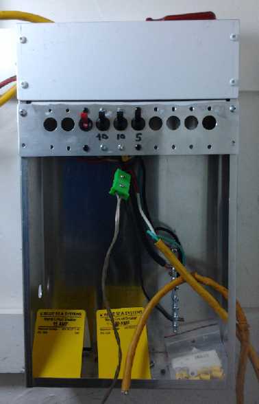
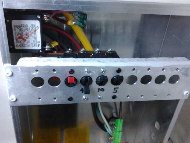
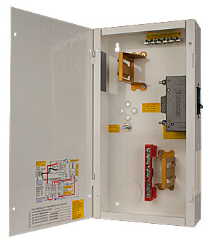
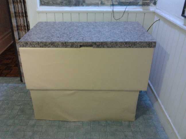
My 12VDC main circuit box
Top panel area is to get some main breakers, meters,
and some 'loose' components.
In September I mounted a 10" wide aluminum chassis box on
the wall in the convenient closet in my office room as the main box. An
external DC to DC converter fed the solar collectors into that, and I
ran a wire down to the kitchen for the peltier fridge.
On October 26th I made a 10" long by 3.25" wide plate and
drilled holes in it (by CNC drill) to mount up to 10 "Blue Sea Systems"
type low voltage DC circuit breakers across the face of the wall box.
This would be the branch circuit breakers. I tied the tops of all the
breakers together with a copper bar, 1/8" x 3/8" profile, the 'main 12
volt bus bar', which would be fed from the multiple sources. I tied a
10 amp breaker to the fridge circuit in the kitchen, and a 5 amp one to
a convenience outlet on (for now, hanging in) the box itself. This was
especially so I could plug an LED light in in the rather dark closet to see better to work there.
The 10" wide breaker "strip" in the 10" wide wall box
reminded me of old 19" electronic equipment racks,
and I decided to see if I could make all the modules fit the 10" box as
a sort of "standard size", at least for my solar electricity products.
Thus all the boxes I made would be 10" wide, with the height being
whatever was needed, and the components would fit that width. This would make for flexible arrangements.
There would be at least two more components in the box: a
DC to DC converter to reduce the ~30 volts from the solar collectors to
about 14 volts to charge batteries, and another panel with "main
breakers" for the solar panels, batteries, and the grid tie-in supply,
plus convenience outlet(s) on the box, perhaps a volt and maybe amp
meter, and a terminal block to hold wires and a few stray components
like diodes, to prevent one supply system from feeding into another or
draining batteries when it's 'off'. The aluminum box offers better heat dissipation from electronic components than a steel box.
Presently I'm using the borrowed Zahn external DC to DC
converter, but I hope to make my own, along very similar lines but
mounting in the 10" space and incorporating the dump load feature.
The 'central'
components I don't plan to fit into the box are batteries and the grid
power supply, which is presently a 12 amp battery charger. The
batteries will have to sit on the floor beneath or elsewhere, as I'm
sure is the usual case, and the charger can be on a ledge or shelf
above the box.
Branch circuit breakers and +12V copper bus bar (too short for 10 breakers but I already had it) feeding them.
Side
breaker (to be relocated to front - then panel can be recessed in a
wall) is the main solar panels breaker. (also fused for faster response)
A drawback to this type of breaker for the output wire is the screw terminals,
requiring a ring or 'fork' connector crimped or soldered onto the end of the wire,
or twisting the wire around the screw, to attach it.
The same type terminals make the copper bar input side simple.
MNDC250 Plus Mini DC Disconnects
(280$ - so far I've spent 100$ on 6 breakers.
My box might be worth 50-75$.)
 Someone
linked me to some available low voltage distribution boxes, but they
seem a bit costly, and they're less flexible. They don't do everything
that's needed, can't be recessed in a wall, and
they'd be hard to add components to.
Someone
linked me to some available low voltage distribution boxes, but they
seem a bit costly, and they're less flexible. They don't do everything
that's needed, can't be recessed in a wall, and
they'd be hard to add components to.
I had been buying circular
hole covers at Capital Iron store, but last time I looked, they didn't
have them any more, and the clerk didn't know what I was talking about.
Oh well - I'll make some hole covers and snap-in plastic wire
clamps with the 3D printer. The clamps will be in two pieces so they
can be inserted after the wire is installed without disconnecting it.
It occurs to me that perhaps the best way to wire for low voltage DC is
the same as with 120 VAC wiring: use the same #14 or #12 house wiring cable (if the
load isn't too heavy), and make connections inside a metal box for fire
safety in case of heat and sparks from shorts or loose connections. The
third wire is superfluous for 12 volts. The bare and negative wire can
be tied together to reduce voltage drop a bit. For 12/24 volts, all
three wires can be used.
I may do a CAT standard for 24 volts. I'm sort of thinking the +24V blade
would 13mm (centers) from the zero volts. That could also do for a dual purpose
12/24 volt
socket with three pins: "- | |".
12 Volt DC CAT Standard Plugs & Sockets System
As I mentioned last month, I had realized the need for
some sort of standard 12 volt DC sockets and plugs besides the
ugly and oversized "car cigarette lighter" type, which was never meant
for the job. As nothing existing looked promising, my proposal was to
base the system on the ATO & ATC
automotive fuse system, but with one blade (the positive blade in the final spec), turned sideways to
ensure correct polarity: the Connector-AT, or CAT Standard. With the 3D printer running, a 12 VDC mains
panel, and the fridge running, it seemed like a good time to get it
going, and at the same time to become familiar with the 3D CAD design
package, OpenSCad.
A first plug was simple: take a blown ATO fuse and twist
one of the pins sideways, then nibble off the top to expose the
contacts to solder a wire to.
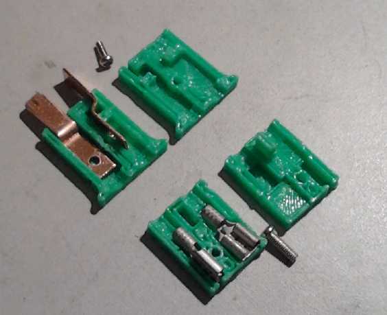
Sockets needed an appropriate housing to position two common blade sockets inside. The Pico part number of the "Universal" .205" blade sockets that seemed to fit the fuses best was 2453 CS. I bought a box of 100. 1853 CS,
which I had when I started, was the same except with a plastic top,
which I had to cut and pull off. I spent a couple of days making
increasingly sophisticated housings, adding an alignment pin &
hole, and finally printing - & + on the case near where the wires come out to help prevent mistakes.
I started with the cross blade being the "-" side. Each
time I went to wire one, I found a strong psychological preference for
thinking the cross side was the positive terminal. After doing just a
few I changed it. I've tried to change all references herein to avoid
causing confusion, and if I've succeeded, this paragraph, and in TE
News #56, are the only references to it the "wrong" way around except
the "+" and "-" signs printed on the first few parts.
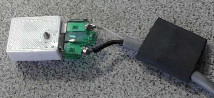
Up close:
The very first
CAT system 12 volt
socket (3D printer, Pico "universal" blade sockets with the plastic bits removed),
and first
plug (a blown ATO fuse with "+" blade twisted sideways and the top nibbled off to solder wires to).
(3/4" heatshrink on wire will shrink over green plug, covering solder joins.)
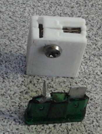
The socket halves could be glued together... after the wires are connected.
But I made a hole for a screw or rivet, too, and this is also how they're attached to covers.

The colored plastic insulators (if any) are pulled off - only the bare metal sockets are used.
Later I added an alignment post, which could if desired simply be melted
as a "plastic rivet" with a soldering iron. (ie, no bolt needed.)
And I made 'proper' plugs, with copper solder-on blades... and a little flange for easily pulling them out.
Here the protruding "alignment" post (barely visible) doubles to hold the horizontal pin in place.
(I'd like to find very small flat-head screws - they'd be flush on the outside.)
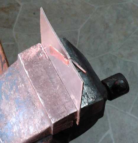
Bending copper to make a CAT plug blade.
The "jig" is just a piece of hard steel (about .040" thick) with a saw cut slit.
Finished plug (solar fridge power cord), sockets, and some cover plates
CAT Standard Plug & Socket Specifications
There's a fair tolerance for dimensions except for the .025" blade
thickness. A thicker metal such as .030" will expand the sockets,
bending the grips so regular thinner blades fit loosely. (Pico makes them - not my fault!) Bent blades
can also cause this problem. Pretty much anything else that fits okay
is fine.
Blade Center Spacing: 9.5mm (same as AT fuses).
Blade Orientation:
The negative connector blade is in line, that is, the same as an AT
fuse. The positive connector is crosswise to the AT fuse, that is,
facing the same way as a 120 VAC wall plug.
Blade Protrusion Dimensions: 5mm x 7mm x .63mm ~(.2" x .32" x .025") (a bit longer than AT fuse 6mm blades to account for socket plastic face)
Blade Sockets: Pico .205 inch type blade sockets (the size AT fuses plug into) or any equivalent or construction that works
Voltage: 12 -1 to +2.5 volts DC, or 11.0 to 14.5
volts -- the CAT spec is for unregulated 12 volts, essentially for
battery power supply. Battery chargers commonly output up to 14.4
volts. (A few chargers go even higher. Avoid those for wiring with CAT
plugs and sockets.) Any equipment having this plug should be made at
least to not self destruct if fed these voltages, up to 20% higher or 10%
lower than 12.0 volts.
Note that a couple of series diodes can reduce the voltage by about 1.2
volts, bringing it down to between 9.8 volts and 13.2 maximum. 13.2 is
just within 10% of 12 volts. +/-10% is the usual voltage tolerance
specification for digital equipment such as computers. (I'll probably
try running my own computers this way... starting with ones I don't
care much about - but I guarantee nothing! Try it at your own peril. I
may also make a low dropout +12V/+5V power supply for the purpose - but
I have a lot of other things to do.)
Superinsulated Thermoelectric Fridge & Freezer
The Shallow Chest 12V Foam Fridge
With less than a cup of
water in a little plastic tray in the fridge, wetting the bottom of the
heatsink on the wall, the water would mostly freeze during the day,
with some water always remaining around the edges and bottom. With the
fridge turned off about 6 PM, it finished melting about 12 PM, and then
the fridge gained a couple of degrees by 7 AM or so (despite the
increasingly cool kitchen temperatures as autumn progressed).
If it would freeze about 3 or 4 times as much water, it
should retain ice and stay pretty cool all night. With the "smart solar
fridge" control, the melting ice would be the overnight energy storage
for the fridge, instead of batteries.
I figured what I needed was something like an aluminum
bread pan to attach to the Peltier cold side in place of the finned
heatsink. Lo and behold, there was one in the drawer of my stove,
amongst several steel ones, all sitting there unused for decades. On the 8th I
mounted that on a vertical plate of 1/4" aluminum with the bolts up at
the top (above the water line). I fit it so the tray was up high on the
fridge wall, so the temperature wouldn't stratify the way it had been
doing, and bent the mounting side so it would sit level. I made a thin
aluminum cover for it so it wouldn't be open water.
This worked badly, the water not freezing, while the
aluminum from the Peltier element hit -9ºc and built up heavy frost. The
aluminum of the pan was too thin to spread the coldness very far with a
smallish contact area.
I tried again on the 9th, this time with the bread pan
sitting on a thick aluminum angle iron "shelf", about 3.5" wide, 1.75"
tall, and 7" long, bolted to the Peltier cold bar. I made holes in the
bottom of the pan and used rubber washers to try and avoid leaks. The
only drawback besides potential leaks was that the pan was too low on
the wall - with no inside fan, the temperature does stratify
considerably if the cold radiator isn't at the top. I may make a new
hole in the wall, higher up, and cover the original.
That worked much better. Half of the litre of water in the
pan froze. The temperature in the pan was thus 0ºc most of the
time, while the fridge was 7 to 9º (at pan height - 4 to 6 at the bottom), the aluminum cold bar from the
Peltier was about -5º, the Peltier outer side was 38º, and
the kitchen was a cool 17º. The ice still melted before morning. I
put a beady polystyrene cover over the pan, which also blocked airflow
between the pan and the wall. The ice lasted 10 hours or so and the fridge
stayed cold longer. I think it's just a matter of how much foam to use
to ensure the ice reserve doesn't all melt in most conditions.
The day after the initial success was foggy, and the
solar panels, reliable all summer and fall in mostly dry sunny weather,
did little collecting until late morning. If I hadn't turned on the
fridge on battery power, the ice would have finished melting and the
temperature risen. So enough insulation to make the ice last 16 or even 18
hours or more would be useful - presuming it would still keep the fridge
sufficiently cold.
Rather than allowing warmer temperatures, I've gone for
the '10 hour melt' and accepted that the mains are going to have to
supply some of the power in the winter. I may try a modification or two
to the Peltier system (losses in the heat transfer could be further
reduced). Magnetic refrigeration would much improve things, but this is
a working fridge.
Turquoise Battery Project
Designing 3D shapes for 3D printer with OpenSCad
Geometric object
designing with OpenSCad is pretty straightforward, tho a bit like
programming in C with lots of "{", ";", empty "()" and stuff. It has
operations in 3D like "translate" (move) and "rotate", and object
primitives like "cube", "sphere" and "cylinder". It can do operations
(all in millimeters) such as "union" and "difference". So a brick with
a hole through the middle might be defined as a 'cube' with a cylinder
subtracted from it:
difference {
cube([80,40,20]);
translate([40,-5,10]) { rotate([0,90,0]) { cylinder([h=90,r=5]); } }
}
I have one special criticism: It would be much easier
to work with if there were "uncube", "uncylinder" and "unsphere"
commands, which would work individually as "difference" shape
primitives, ie, they would be subtracted from the object without
invoking the structured "difference" command. As it is, having to nest
"union" and "difference" commands at multiple structure depth levels
gets needlessly convoluted and confusing. With the "un-" primitives,
everything could follow everything else in a simple linear sequence.
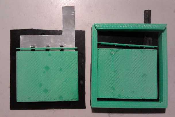
Printing Porous Electrode Pockets (Yay!)
I had a great, working chemistry in
February, then I got sample porous plastic electrode pockets 3D printed
at
VICAMP/Camosun College in the spring to test the idea. At last, getting
my own 3D printer working allows preparing to produce actual
batteries.
One problem was to find zinc for the negative electrode
current collectors. Snipping it off old "D" cells works, but is hardly
practical for long. Finally I thought that it might be used for roofing, to kill moss. Sure enough,
Rona building supply had it in 25 foot rolls, 68mm wide!
That width was too short for the battery height, so I
decided to design around that width, the height then being whatever length I cut off. An electrode plate of 4 pockets of
about 15mm wide with 3mm ribs between pockets would cover it. In the zinc I cut
three 4-5mm wide, 60mm long slits, dividing it up into 4 fingers to
insert into the 4 pockets, with a cross piece above, and a further
vertical piece to go up out of the cell for connections.
Since the carbon fiber 'posode' current collector widths
could be adjusted, it seemed reasonable to make all the pockets
identical. (If necessary the thickness could be tweaked to enclose the
right portion of amp-hours of chemical for each side.)
Although it seemed something of a waste of current
collector and plastic, I decided to make the porous pockets single
sided.
They could be glued to solid plastic backs and then stuffed with
chemicals. These could either be loose electrodes to insert into a
battery, or larger plastic backs themselves could form the faces of a
narrow
battery cell. These would then be glued to opposite faces of a 3D
printed "U" piece to form the bottom and sides of the cell. or, better,
to a four sided frame piece. (That just leaves the filler/air blocker
cap part.)
The pockets could of course be easily changed to double
sided simply by gluing two back to back. But it seems hard to keep
the current collector in the middle to fill both sides evenly. I'll keep it as a future possibility.
The plates could still be made double sided by gluing an electrode
pocket to each side of the solid piece. These could then be stacked as bipolar electrodes
to make any voltage battery as a single unit, having somewhat less
plastic than individual cells, or could have the same polarity on each
side, to be inserted as loose electrodes into a fatter cell with more
amp-hours.
I became worried about the ABS printing looking quite
good, and not at all porous on the bottom layer. But I learned that the
amount of plastic being put down per millimeter is controlled by a
command to the printer. If it's set low enough, the print was bound
to come out porous.
Eventually I worked out the following special practices
for printing electrode pockets. They apply specifically to the
ReprapPro Mendel 3D printer and may only be a rough guideline for
others:
1. Turn the Z axis stop adjust out about 1/3 to 1/2 of a turn. This puts the
first layer a little high, so the plastic comes out in more of a
cylindrical shape instead of being flattened against the glass into an
oval.
2. The amount of plastic in "pixels per millimeter" is set by a g-code
command. When the printer is turned on, it defaults to 980. Edit the
g-code file and set it to a lower value before any print commands with:
M92 E600 . This will print thinner filaments.
The plastic tends now not to stick to the glass, and lines may curl up.
Some finer adjustments of 1. and 2. may be necessary to get a good
first layer, yet with some gaps between the lines. Also get the bed
plenty hot, 100+ºc. I can't get mine up to 100 without putting
some sheets of paper on it to insulate it. I remove them just before I
hit "print". (No fires - so far!)
3. For the second and third layer (Find and insert after a "Z" move up
to the next layer), increase the density a little: M92 E700 .
4. For the fourth and subsequent layers, which are the walls around the
pockets, increase it to normal: M92 E980 (or whatever your 'normal'
seems to be). If you don't, the walls will be thin lines with gaps
between each line - not the best or strongest surface to glue.
Save the file, and if you've used an external editor, reload the g-code file in Pronterface. (The internal editor
in Pronterface seems to have no "Find" command so it's very hard to find the
"Z" axis moves - the start of each new layer.)
If you can hold the "plate" up to a light and see pinpricks of full
light, it's successful. If you can't blow or suck even a little air
through it, it's not porous. If powder comes out through the holes,
they're too big.

In many areas, light can be seen through this electrode, so the holes there are plenty big enough.
Where light can't be seen it's debatable. They got more consistent as I refined the techniques.
I'll upload the plate design to thingiverse.com . I made the
bottom thick enough that it prints three layers, which I felt
(literally) seemed strong enough. The top cover prints a little
lightly. It might be best to print top covers separately, or else to
locate which parts are the lids (Y co-ordinates > Ymin + 60) and
insert sufficient "M92 E980"/"M92 E700" commands in the first three
layers to print the right parts with the right density.
Stuffing the Pockets
First I decided to go for the basic idea of gluing the
pockets to the inside faces of a thin battery as illustrate. If I made a bad plate, I
could still cut the outsides off and have the good plate as a loose
plate to go inside another cell. So I glued two successful prints to 1/8" ABS sheets large enough for the purpose.
Then I considered that if I built the pockets into the
walls of the cell, I couldn't remove them for inspection. That's great
for production cells, but I want to remove them and see if any powder
has leaked out, and if so how much. So I decided to try again with the
plates glued to like size plastic sheets so they could be inserted into
a test cell, which I have yet to do.
I considered that if I just started cramming electrode
substance into the glued pockets, the pressure would probably cause
many to pop open or bulge too much. The thing to do seemed to be to
sandwich the plate between two pieces of steel and stuff them within
that. So I also need a jig for that.
Magnetic Motion Machine Project
I had been wanting to
get back to this project for months, since it could be such pivotal
technology if it can be made to work. Cloud cover was minimizing solar
collection, and 'thermomagnetism' might make a generator that didn't
depend on weather. (I'm starting to think, tho, that it's probably
actual atomic or nuclear energy that's harnessed via magnetism, not
simply the ambient thermal energy of the materials.)
The design from May (TE News #52)
was still untried. On the 27th I got out the round board I'd been
laying out the machines on, and decided the big block of wood in the
center had to go. In the center of the board was then a 1-5/8" hole I
had made with a hole saw. Since I wanted a bearing and vertical axle in
the center, it had to be filled in. Hmm... How about making a part both
to fill the hole and to hold the bearing, with the 3D printer? That
took
a couple of hours, but it was probably as fast as anything I could have
devised, and it did everything.
Then an assembly for the center magnet was needed, to fit
securely on the top of the center axle and to hold the 1" x 1" x 1"
magnet. I decided a thick floor would mount it on the axle, and to have
a box on that to exactly fit the magnet. In three quarters of the
rotation, magnetic forces would push the unit
forward (clockwise). Only in one quarter the magnets would try to twist
the wrong way, creating a backwards thrust. If I shorted out the
field on that side with a piece of steel, the arm magnet there would
attract to the steel and would have to be somewhat pulled away from it,
but the strong contrary twisting force would be
much reduced. There are other possible expedients which should reduce
the force even more, but this was the simplest one.
So I designed the assembly in OpenSCad and printed it on
the 3D printer as well. Again, it took no more time than any one-off
part I could have made, and it had all the bolt holes and everything,
machine perfect. (The printer then took over an hour forming this
little cube - but that was mainly its time, not mine.)
The magnets and steel piece fit well and the unit turned
freely. Whether the theory that it should turn held or not, at least it
had the benefit of being well made with machine precision, to give it
the best chance.
Then there were the stator magnets on arms with push-pull
rods to the center 'armature' unit. I decided I
would try just 3 magnets at 120º angles to give a balanced 3 phase
effect. In theory, at any point or time, two magnets would be pushing
forward, at least one strongly, while just one might be pushing
backwards,
hopefully rather weakly.
Let's see... three arm assemblies! This time it was
a no-brainer. If I used the 3D printer, I'd only have to design one,
then the printer could print it in triplicate. And if I decided it
should have five arms instead, there'd be no more work except
installation.
I played around with a couple of magnets (I only have 2
hands and the magnets won't stay put) around the central 'armature'. I didn't
really get much of a feel for what ought to happen, but it seemed to me
it might well work, and even as I designed the arm parts, I started
thinking of adding a pulley to the armature, for a belt to turn a small
electric motor/generator. Making a plastic pulley that glued to the
floor of the armature unit would be simple. Then - if it worked - it
could make a bit of real electricity.
Experimental machine with rotating center magnet and three arm
magnets that pivot back and forth. Magnetic attraction and repulsion
were to push the pivot around, but direct magnetic twisting forces are
stronger, suggesting modifications.
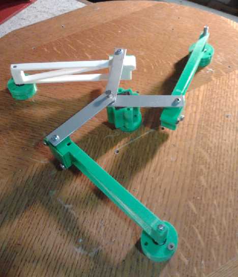 It didn't work. It swings through some spots, and come to a halt at
others. I found that a single arm would cause a swing of about 200
degrees or 230 derees, depending on the magnet arrangement. The rest of
the circle has reverse thrust. Rather than the way I originally had it
with the flats of the arm magnets facing the center, it works better
with the edges facing.
It didn't work. It swings through some spots, and come to a halt at
others. I found that a single arm would cause a swing of about 200
degrees or 230 derees, depending on the magnet arrangement. The rest of
the circle has reverse thrust. Rather than the way I originally had it
with the flats of the arm magnets facing the center, it works better
with the edges facing.
There are lots more things to try. I found that the direct
magnetic twisting force of the magnets seems stronger than the
mechanical twisting force gained from the attractive or repulsive force
pushing or pulling on the pivot. Thus, the pivots should be arranged so
as to bring the arms close when the magnets are twisting the right way
and push them away when they're twisting the wrong way. The pivot point
needs to be on a diagonal for that.
More arms with magnets should also help. With only three,
the angles are such that there are positions where two magnets are
resisting turning and only one helping. With four arms that would be 2
and 2, and more positions with 3 and just 1 resisting.
There may be interactions between the arms that I'm not
accounting for, too, and the more arms there are, the more strongly
they'll interact. And the arms could be made to mechanically interact,
too, by various linkages (and changes to the center linkages). An arm
that has moved into the forward twisting zone could shove one that is
entering its countertwisting zone away from the center magnet to reduce
its magnetic interaction, perhaps almost without friction.
Another thing that could help is a flywheel. Inertia could
carry the unit through resistive spots as long as the overall effect is
rotation in one direction, whereas now rotation comes to a quick stop
in regions of counter force.
October ended before such new ideas could be tried out very far.
http://www.TurquoiseEnergy.com
Victoria BC