Turquoise
Energy Ltd. News #58
Victoria BC
Copyright 2012 Craig Carmichael - December 4th, 2012
www.TurquoiseEnergy.com
= www.ElectricHubcap.com
= www.ElectricWeel.com = www.MushroomOutboard.com
Features: Peltier Element Heat Pump for
Home & EV Heating (see Month in Brief)
Month In (relatively) Brief
(Project Summaries... and many little things not warranting separate
report headings)
- 12V Peltier element Fridge is cold enuf: probe has been reading
2º
too high! - Peltier Element Heat Pump for home & EV heating - 3D
Printing: a 12V NiMH battery case - Battery Making - "Mini Electric
Hubcap" +
Bicycle Rim Motors - Mushroom Outboard: preparing for 'pot metal'
propeller
casting - aluminum casting
for heatsinks - Torque Converter & Sprint Conversion - Greentech
Exchange Solar Event, Cheap solar heater, & Crowd Funding.
In Passing (Miscellaneous topics
and editorial comments)
- Banking and the Fiscal Cliff: history and beyond it
Planetary Gear Torque Converter
Project
* Balanced ropes + 1 to 1 flat belt + trial with no great results
Mushroom Outboard Motor Project
* Preparing to cast the propeller
CNC Farming Machine Project
* How did I get onto another
project? Don't I have enough unfinished projects?
* 18' Wooden Ladder Gantry: easy to make into a
supported truss - wheels & tracks - motors - drive belts
Superinsulated 12VDC Peltier Element Fridge
Project
* Is colder than measured - cold enough to use
* Commercial & Homemade Aerogel possibilities
Large Format NiMH Batteries - Take 3
* 3D printed, ventilated, stackable 12 volt battery cases minimize size
and added weight.
Turquoise Battery Project
* First porous plastic electrode using my 3D printed electrode pockets
is...
* An iron electrode with improved current capacity, charge rate and
charge retention
* "Graphite Foil" & "Flexible Graphite" likely best solution for
posode current colletors (now on order)
No Project Reports on: Electric Hubcap System, Weel
motor, DSSC
solar cells, LED Lighting, Pulsejet steel
plate cutter, Magnetic Heat Pumping, Magnetic Motion Machine
Newsletters
Index/Highlights: http://www.TurquoiseEnergy.com/news/index.html
Construction Manuals and information:
-
Electric Hubcap Motor - Turquoise Motor
Controller - 36 Volt Electric
Fan-Heater
- Nanocrystalline glaze to enhance Solar
Cell performance - Ersatz 'powder coating' home process for
protecting/painting metal
Products Catalog:
- Electric Hubcap Motor Kit
- Sodium Sulfate - Lead-Acid battery longevity/renewal
- NiMH Handy Battery Sticks, Dry Cells
- LED Light Fixtures
Motor Building
Workshops
...all at: http://www.TurquoiseEnergy.com/
(orders: e-mail craig@saers.com)
November in Brief
My September 19th, 2012 Talk at VEVA
(@ BCIT, Burnaby BC)
The Vancouver Electric Vehicles Association
video of my talk at the meeting was
uploaded in October. (I'm just late getting around to some of my
e-mails.)
Craig Carmichael of Victoria BC presents his alternate energy
inventions
Part 1 - http://youtu.be/MPaP8pnRukw
Part 2 - http://youtu.be/a5d3azR8O8Y
Part 3 - http://youtu.be/F_fx4AoLMEE
I confess... I haven't watched it yet.
Solar 12V House Wiring and Equipage
I used the 12 volt plugs and sockets for a convenience
outlet in the main panel (for an LED light to illuminate the dark
closet)
and for the Peltier/solar fridge. They work. I didn't cut a box into
the wall near the fridge yet, so the wire is just hanging there. I keep
thinking there must be some smaller box than an 1110 electrical box, to
cut a smaller hole. Or a surface mount box. Since
I haven't had time to make more LED lights, I bought some sample LED
bulbs at Deal Extreme. One 'cool white' (6500K) one I especially liked
and soon ordered a few more. According to the figures given, it's just
10 watts and 1100 lumens - fabulous efficiency. I haven't measured the
power, but the brightness is there. Some reviewers at DX.com said it
was equivalent to 75, 100 or even 140 watts tungsten. One of the
samples burned out instantly. Later I printed out my order and found
that it was a 12 volt bulb, with a standard "E27" 120 volt base. Rats,
I wrecked the one for the solar power!
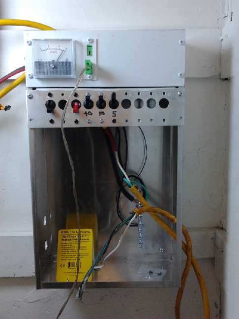
The main panel by month's end.
Not much progress, but the voltmeter looks nice
and the 12VDC convenience outlet for the light is the first one
properly installed.
An ampmeter would be a good complement to the voltmeter, but my
matching
one goes to 5 amps instead of 50. (They were bought for testing wave
power.)
The 12V Peltier element fridge
is better
than I thought. The multimeter thermocouple probe was reading
about 1.5 to 2º
too high. When the meter read 8º, it was really 6 or 6.5º. At
the floor near the ice tray, it apparently hovers
around 3 or 4 and gets as low as 2. This was more in line with
expectations
considering the nearby ice tray and the 3" foam insulation.
With temperatures now seeming cold enough, I started
using the fridge for some day to day things. It's unexpectedly nice
to use. The light 3" foam lid opens with a touch, and then you just
drop it the last few inches. It closes itself really quickly, with a
'whuff' of air cushion at the end. Everything is
accessible just as I'd envisioned. Since you're not reaching behind
things to get other things, the time the lid is open is usually very
brief, with little heat gain. And the cold air doesn't dive out the
bottom when it's open like a front door fridge.
I still need find time to make and program the smart solar
control and do
the drain
funnel for under the ice tray.
Main hot side plate, cold side angle aluminums.
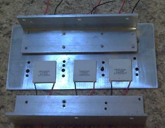 But on the
25th, I got my nephew to cut and drill holes in
the pieces I'd selected for an experimental peltier element heat pump.
It has 6 peltiers at up to about 100 watts (input) each, in two rows of
three. In operation at full power, each peltier cold side could be
expected to
cool with about 40 watts, and the hot side to heat with 100 + 40 = 140
watts. Thus the total potential was 600 watts input yielding 840 watts
of heat on the hot side.
But on the
25th, I got my nephew to cut and drill holes in
the pieces I'd selected for an experimental peltier element heat pump.
It has 6 peltiers at up to about 100 watts (input) each, in two rows of
three. In operation at full power, each peltier cold side could be
expected to
cool with about 40 watts, and the hot side to heat with 100 + 40 = 140
watts. Thus the total potential was 600 watts input yielding 840 watts
of heat on the hot side.
The EV is the most interesting installation here, as the
heating power has to be supplied by the same batteries that power the
motor, and in winter, driving range is substantially reduced by the
heater/defroster. A heater delivering any extra heat for the power is
thus
highly attractive.
However, a reduction in power bills would mean a peltier
heat pump is also economic for home heating versus electric baseboard
heat. All else being equal (mostly assuming peltier elements have
decently long service life), the power savings will rapidly eclipse a
higher unit cost.
Outside heatsink fins
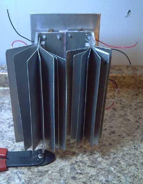
In my unit, the heatsink fins go vertically. I'm hoping
the outdoor cooling side can be convection reheated. (Should work on
windy days, anyway. In a car, the car is moving.) The inside will have
a fan. It
could be window mounted (or in my case placed in an existing hole I had
made long ago
in the wall for a passive "Trombe Wall" solar collector, now long
gone), or
installed in a car. I would hedge the bets: for experimentation and
initial use it would use the wall hole and run on a 50 volt, 5 amp
transformer with 5 elements of the 6 in series, to draw just 5 amps for
a 250 watt input, yielding 350 watts of heating power. But with minor
rewiring of the elements into two banks of three, it would become a 36
volt, 300/600 watt car heater (with 420/840 watts of heating).
On the 26th and 27th I started putting it together. The
details of the hole drilling weren't very well thought out and holes
didn't work out or even line up. The warm side heatsink fins were hard
to fit on and then they didn't conduct the heat very well - a critical
problem. I made notes for next time. (I should have had my nephew
assemble it. He'd surely plan out and execute the job much more
carefully next time.)
I also began to realize that some of the "aluminum" fins
were probably some sort of alloy - they weren't attracted to magnets,
but they seemed much harder to bend than aluminum. It has to be pure to
conduct heat well.
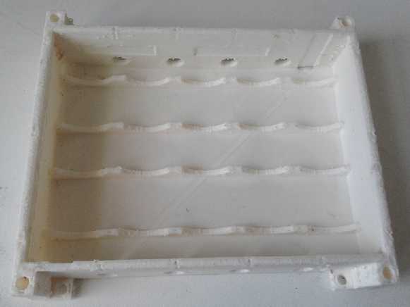
3D Printing - 12V NiMH D Cell Battery Holder - out of order
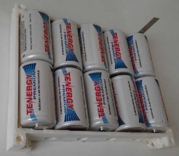 On the 5th I was
printing a D cell 12V battery holder. About 3 hours into the 5 hour
print, things came to a sudden stop and there was smoke coming from the
printer.
On the 5th I was
printing a D cell 12V battery holder. About 3 hours into the 5 hour
print, things came to a sudden stop and there was smoke coming from the
printer.
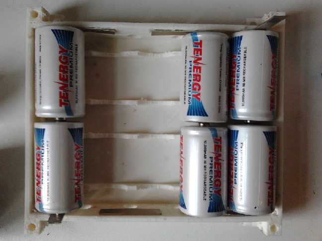
There was enough printed to put in some batteries and try
it out. It works. Complete cases will be stackable to create large NiMH
batteries in multiples of 12V and 10AH.
For the printer, I had visions of fried circuits, having
to order a new circuit
board, major rebuilding to do, and delays getting projects done.
I had tried successively higher temperatures to get better
results printing ABS, and this one was the hottest try yet, 270ºc.
Fresh plastic lines sagged too much covering over holes and I wouldn't
have gone quite so hot again. Probably 250º as suggested some
places was about right. I was trying to insert bits of cardboard
'insulation' to minimize warping, and evidently I hit the extruder
temperature sensing thermistor wire when the carriage moved towards me.
(Duh
- the printer can be paused!) Somehow this must have shorted
something out - the thermistor blew apart and the
insulation of its wire was scorched all the way along the ribbon cable.
Bad
temperature readings is probably what stopped the printer. It turned
out
that the thermistor and its wire seemed to be the only problems -
otherwise,
everything still seemed to work. Digikey was out of those thermistors
and I had
to back order. (and now they're to be further delayed!) Sigh! With the
3D printer out of order, I turned to
other
things. The magnetic motion machine was out too, as I wanted to print 3
more magnet arms for it.
Battery Making
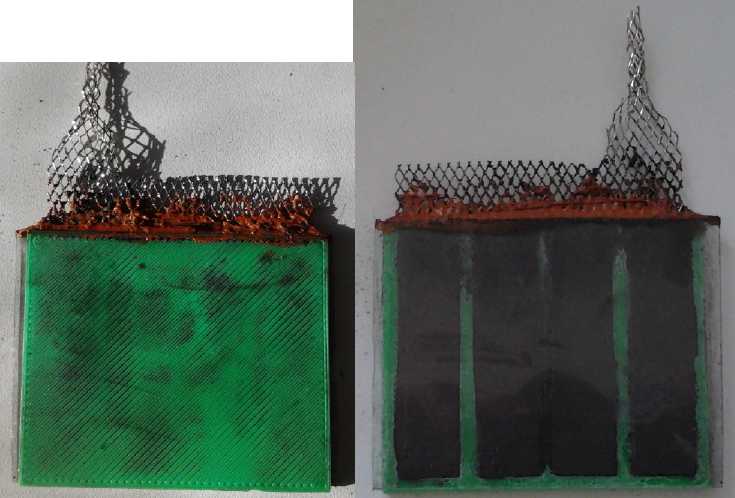
A porous plastic electrode. See-through plexiglass
backing plate shows the active chemicals.
Fine powder on green face leaked through the coarse pores.
Nickel plated copper mesh current collector; RTV silicone to
seal the top (unsuccessful - it turned to goo in the electrolyte).
 I took porous ABS electrode
pocket covers I'd
already
printed and made 3 electrodes. Two attempts to make a monel electrode
with the monel mix I made in 2008 plus some graphite were failures.
Only later did I remember that metallic nickel has the unusual property
of not oxidizing in strong alkaline solution. Duh! It should work okay
in my
"moderately alkaline" electrolyte, but the point here was to make a
single electrode and test it in a Changhong Ni-Fe cell with the
original nickel 'posodes', where everything but the test electrode
would be a known, working quantity.
I took porous ABS electrode
pocket covers I'd
already
printed and made 3 electrodes. Two attempts to make a monel electrode
with the monel mix I made in 2008 plus some graphite were failures.
Only later did I remember that metallic nickel has the unusual property
of not oxidizing in strong alkaline solution. Duh! It should work okay
in my
"moderately alkaline" electrolyte, but the point here was to make a
single electrode and test it in a Changhong Ni-Fe cell with the
original nickel 'posodes', where everything but the test electrode
would be a known, working quantity.
The third attempt was a successful iron 'negode'. It
contained 25g of coarse ferrous oxide "sand", 10g of monel
alloy, and .35g of antimony sulfide, and had a copper foil current
collector. I used the coarse powder because the nano powders in the
first two had been leaking through the pores in the plastic. I still
put a piece of watercolor paper across the face when I installed it in
case any came out. Scaled for size, it seems to work a little better
current-wise than the original iron electrodes, despite being twice as
thick relative to the current collector. Theoretically it's 17
amp-hours worth of iron, but it looks like it's attaining around just 2
or 3%
utilization. This is probably because the coarse grit has low surface
area for its volume - most of the Fe is in the interior of the grit
particles where the electrolyte can't reach it. But it has the
following theoretical improvements:
* The monel makes it more conductive. This leads to ability to take
charge faster or more efficiently, and to drive heavier loads with
lower losses. Pure copper powder should be as good or better, but
monel (Ni:Cu ~~67:33% alloy) is what I had. The concentration needed to
attain really good conductivity
needs experiment. Furthermore, I didn't get to see if the graphite
powder would have worked. From the voltages it seems it should, but I
heard from one source that it bubbles hydrogen and discharges the
electrode. The Sb2S3
stibnite just might make the difference to that problem if it
exists. But since Mn-Mn is a wholly
better chemistry, I'm not going to bother perfecting this one.
* The antimony sulfide raises the
hydrogen overvoltage. This reduces bubbling of hydrogen gas, which in
turn improves charging efficiency and charge retention, reducing if not
curing the most negative characteristics of typical nickel-iron cells.
(Hydrogen evolution may perhaps be reduced to the point where
nickel-iron dry
cells
become practical.)
* The plastic electrode body is cheaper than metal ones. Also it can
touch other electrodes without causing a short circuit, so they can be
more closely packed inside a cell.
All this has allowed me to make single electrodes to use
with existing nickel ones and compare against known iron ones. It's
good
practice, learning, and test of a couple of theories, and has refined
my cell design ideas and led to improvements such as sealing the top of
the electrode pockets with wax. But the similarly long life and higher
energy 2 volt manganese cells are still the main object.
I shot video footage as I made the electrodes, and I
"copied" them onto a Windows PC machine, then erased the camera to free
up the space. But it turned out the computer, despite long clips taking
quite a while to "transfer", had only made "aliases" - links to the
files on the
camera. I discovered this only when I went to edit it all into a
battery making video. Only the names of the file clips remained on the
computer, claiming they were the videos but with no data. Instead of
editing the video and getting it online, I made another electrode and
shot more footage. I didn't get around to making it into a presentable
video.
I read a new term "graphite foil" and on searching for
that found rolls of "flexible graphite" on line. Was this what I've
been missing all this time for positrode current collectors, for want
of which I've been doing carbon (graphite) fiber and the grafpoxy mix?
I ordered some and a large roll arrived December 4th just as I was
finishing up this newsletter. It looks like a thinner version of
"expanded graphite". (And I wish I'd ordered .010" instead of .020".)
But I'll try a few things - in particular chemical surface preparations
- and try it in plastic pocket electrodes, and see what I can do with
it. From their cycle life graphs, it appears Aquion got good results
and long life out of their "graphite foil".
Electric Hubcap Motors
A couple of people were interested in smaller motors for
converting small motorcycles and scooters to electric, as well as the
motor
controllers and new chemistry batteries. I had thought of a smaller
diameter "Electric Hubcap" motor, which would have 6 coils and 8
magnets instead of 9 and 12. To keep things simple, they'd be made much
the same way with the same components. They'd be 24 volts, ~3KW, 3000
RPM, 9" in diameter with about a 7.5" rotor, and ~22 pounds.
In looking at some youtube videos of motors for bicycles I
started to consider (tho not for the first time) a big "partial rim"
motor. This is made in two separate parts. On the wheel, well out
towards the rim (probably attached to the spokes) is a steel ring
mounting supermagnets. The larger the wheel, the more magnets are
required. The wheel becomes the motor's rotor. Attached to the frame
facing the magnets is an arc of coils, a "fender" to the side of the
wheel, rather than a complete circle. This drives whatever magnets
happen to be across from it at the time.
I think 3 "Electric Hubcap" coils might give a minimal
ride on level pavement, 6 would give a good ride, and 9 would
(probably) be overkill on a regular, lightweight bicycle. An
interesting feature is that for magnets at the rim of any wheel, a
small wheel will theoretically perform the same as a large one - the
torque available
is proportional to the torque required for the size.
Mushroom Outboard & Marine
The fisherman who wanted to troll electrically last spring
called again on the 10th, and I still haven't made an outboard. I still
have the Honda outboard leg, but my 'production' Electric Hubcap motors
still won't quite fit under the hood. I talked with Jim Harrington who
has converted a couple of outboards to electric. An appropriate motor
that would fit wasn't kicking around, so we decided to use a sealed 3
HP Leeson DC
motor and controller that he had surplus at AGO Environmental, and
hence available at low cost, and install it as an inboard to drive
his main propeller shaft with a V-belt and pulleys, in order to get him
going for next season.
I like the direction switch on the controller: when
flipped from forward or reverse, it stops at neutral. It can't be
flipped from one direction to the other without stopping and releasing
pressure on the switch at neutral. Where do I get these for electric
cars?
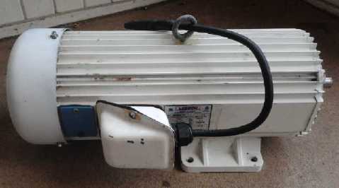
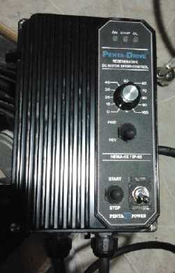
3 HP motor & controller for fishing troller inboard
Along with the battery making, I collected up supplies and
equipment to cast the extra-efficient looking propeller for outboard
motors. Not exactly an invention on its own, but perhaps a product in
itself. And the smaller, higher RPM motors would fit in the Honda
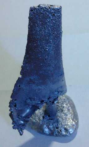
outboard leg, which could make that a good one-off product. In my first
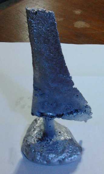
attempted casting on December 3rd, I realized in the nick of time that
zinc-aluminum alloy would doubtless corrode rapidly in salt water.
Melting pure aluminum on the stove worked
out badly, tho it did melt and I'll try it again, and I used the
mini-kiln. The first
propeller blade cast had air pockets and gaps. It wasn't usable.
(...fill the gaps with epoxy?) But since it was my first ever attempt
at metal casting, I sanded and polished up one face a bit for a
picture. I examined it with a friend with casting experience and we
discussed how to get better results.
Along with casting the zinc-aluminum alloy propeller (now
itself pure aluminum), I
started to think it might be nice to cast straight aluminum, perhaps
with fins: for
heatsinks. That had the potential to speed up making several items from
motor controllers to peltier element heat pumps. I was seeing various
ways people were melting aluminum and got so intrigued I forgot about
the
obvious one. I was dubious the hotplate would be practical. On the 25th
I tried melting some in a pottery crucible in the woodstove, but it
didn't get hot enough where I set it. A propane torch did the trick
eventually, but used a buck or two of propane. I read about making an
induction heater to melt aluminum. I
looked up the actual melting temperature (660ºc), and realized my
electric mini kiln could do it. Duh! Problem? No problem! On the 27th
in about an hour I successfully poured a small ingot of aluminum into a
muffin tin
hole, tho with lots of slag left over. It's doable. I couldn't clean
out the pottery crucible - the stuff was stuck
solid into the pores. Then I found one can melt aluminum on a kitchen
stove burner in a stainless steel pot. (See the "Mushroom Outboard"
project report for details.)
On December 1st I found a source of pure aluminum drill
shavings that had been just going into the garbage. I took a big but
pretty light box of them. If I do much casting I'll be back!
Electric Car & Torque Converter
I got the last piece of the new "balanced pull" slip
clutch tensioning system done on the 14th. On the 15th I put the 36
volt battery on charge and since it wasn't raining or too cold, I
started taking things out to the Sprint car and reinstalling them.
Before, I could hardly stop the rope from holding the pulley stopped.
Now it needed far too much pressure to get much drag on the pulley.
Maybe I'll try some kind of noose arrangement.
I didn't get the car to move. I think I was too optimistic
and should have stuck with the 4 to 1 chain reduction drive for now.
With the 1 to 1 belt drive, the converter could be putting out even
twice
the torque now, and still there'd be only 1/2 as much to the wheels.
Belatedly I thought about the elementary step of measuring
the torque on the shaft with the torque wrench, whether the car moves
or not, or even without connecting to them. After all, I ground a hex
shape into the end of the shaft for that very purpose. It proved pretty
useless for measuring pulsed torque, but I should have
been doing that from the beginning of the PGTC to measure results.
Greentech Exchange - Cheap solar heater
On the 29th, after spending the day on brochures and an
ad, I went to a Greentech Exchange Panel Presentation on Solar
Energy. One speaker who couldn't make it in person from Seattle
presented via Skype. His voice and projected face reminded me of
"Hollie" from the Red Dwarf TV show, but it worked.
His presentation was on having black metal with holes or
black cloth facing the sun on a south wall and drawing solar pre-heated
fresh air into the structure through it via a duct near the top. This
meets HVAC fresh air requirements with less energy when the sun is out.
It looked amazingly simple and cheap. I wonder how it would work with a
return air hole at the bottom and solid black material? It sounds so
simple I may just revive my old "Trombe Wall" from 30 years ago, but
needing no glass or transparent plastic on the front. (Of course, the
grape vine and other leaves would still shade it over except in early
spring.)
As invited, I set up some demos of solar 12 volt stuff and
the papers on one of several tables in the lobby. It sounded like most
of the
panelists could really use one or more of the things I've been
developing, and in the question period I said something about that and
to take my card if we couldn't find time to talk.
Rob MacGregor, the BC director of Sun Country Highways
spoke with me
afterwards about batteries. Sun country is building a network of EV
charging stations across Canada so that electric "transportation
appliance" drivers will have somewhere to go to recharge wherever they
are. This addresses the biggest fear about EVs: running out of power
somewhere.
(Someone is presently driving coast to coast, Newfoundland to Victoria,
in a Tesla. But there are many gaps still to be filled for shorter
range EVs.) The
second biggest complaint about EVs is the length of time it takes to
charge the batteries, so a cheap, very high rate cell would be an
excellent thing to have.
I also talked with three mechanical engineering students
who were about to graduate and mentioned my lagging torque converter
project. It seems likely that one of them will contact me after their
final exams.
Crowd Funding?
Something I've noted repeatedly in my inventive career is
that while I work on creating things to benefit everyone, almost no
particular person or body feels it should devolve upon them to
help foster or fund such projects when they are only one of the many
who would
benefit. In "R & D", Development has been the neglected little
brother of Research.
With some products now proven in principle and mainly
needing setup for production, and all these markets for them,
I may
look into "crowd funding", which
I've been hearing positive things about lately. People who wish to
create new
things are being funded not by rich "angel investors" or "venture
capitalists", but instead by a "crowd" of ordinary people who like the
idea and each contribute a small amount. Various terms and conditions
for the funding are specified in advance, so the proponent and
the payers are all clear what is expected.
Thus projects to benefit the many may be funded by the
many, each to a small extent. I could certainly have used something
like that for previous great (IMHO) projects that impressed people and
got good lip service, but went nowhere owing to
lack of investment! But the Crowd Funding idea and implementation
itself is a recent invention.
But there
may be other ways of funding, and there are often ways of setting up
smaller scale production that cost less and reduce or even eliminate
obligations incurred in order to get going.
In Passing
Incidental news, editorial opinions
Banking and the "Fiscal Cliff"
Like most people, I've never paid much attention to the
world of finance - until recently, when it started to look like
catastrophe is looming and lone lunatics predicting the end of the
world were joined by a rising chorus of variously qualified people
predicting such a
terrible financial collapse as might bring about the end of the
civilization we have known for many, many generations. Even the last Globe
and
Mail newspaper I saw had the term "fiscal cliff" in several
Business section articles. I started
to think I should at least try to understand why it's happening.
Youtube seemed like a place to see what "financial
collapse" was all about.
I think The best
overview explanation of hyperinflation and monetary system collapse
I've seen is a short two part video by Argentinian Adrian Salbuchi.
(Search youtube for that name.) He says the cycle of monetary collapse
is shorter in Argentina, and that they have gone through 3
hyperinflations and monetary collapses since the 1960s, whereas for us
in the "first world", all we know of the subject is old pictures from
the 1930s (yes, millions did die of starvation and poverty), and our
"normalcy bias" keeps us from believing such a thing
could happen again here. He held up an old Argentinian Peso and said it
would take trillions of them to buy what one would buy in 1964.
A lady named Ann Barnhardt said she closed her farm
commodities brokerage in 2011 because after MF Global and PG Best stole
all their customers' money ("and John Corzine still walks the streets a
free man!") and then court
decisions and new laws excused such theft, she decided that rule of law
is
gone and she could no longer
guarantee her farmer clients wouldn't suddenly have all their money
stolen.
She advised them all to "get out" and keep their money in cash or
precious metals. Her definition of what money is is worth hearing, too.
One person said that precious metals were an okay temporary
hedge, but that America was becoming a "third world" country and was
likely
to remain so for 5, 10, 15 or 20 years. He had lived in several of them
and thinks that the only real riches in that situation is to have the
means of producing something people need. Everybody needs food, and he
had put all his money into a piece of land, a farm that that he could
grow crops on.
And there are many other points of view on the "fiscal
cliff" and beyond on
Youtube.
Salbuchi's proposal to have the government directly
print money for
specific public works, tax earnings appropriately, and then (hopefully)
destroy any
excess if there's too much in circulation, sounds much better to me
than borrowing it from private banksters, to be repaid with interest.
Where is the money for
this interest to come from if the government can't print money? It has
to come form money already in circulation. And if money can only enter
circulation by a loan from a bank, it becomes a vicious circle of debt
and more debt.
Is it any wonder
then that debts grow and grow until
the Whole World owes far more money than exists, far more than can ever
be
paid 'back', and is now galloping full speed over the cliff of an
incredible financial catastrophe?
We must prepare with reserves of food and other needs, but
ever be mindful there's a tomorrow after that
collapse. The collapse will be a horrific event which may take many
years to straighten out, but the banks have outscammed all the corrupt
businesses through which a few families have controlled 80% of the
world's economy, and hyperinflation or national bank failures will
eliminate their vast monetary wealth. By the time things are
re-starting, the power base of the corrupt will have
been eliminated, and the world will be on a new, more sustainable and
more spiritual track. Many of the
fiscal cliff "prophets of doom" think the long term future will be much
brighter. "The sooner the better." they say. A global change in
consciousness can already be sensed.
A focused bit of American Financial History (an inevitably
slanted view)
There's nothing new in financial collapses, except for the
global extent and the
extraordinary degree of control the main banksters have attained over
governments everywhere and over
everyones' lives and fortunes - their ability to
extract the wealth from most everyone, everywhere, by fraud. They foist
worthless "credit derivatives", "credit default swaps" and
"collateralized debt obligations" - weapons of financial terrorism
rated "AAA investment" by the corrupt ratings agencies, who are
under their control - onto other banks, pension plan funds,
municipalities and other unsuspecting saps, running to trillions of
dollars. Where
in the early 1930's 1600 US bankers
went to
jail for their roles in causing the great depression, banksters and the
ruling "cleptocracy"
caused the 2008 crash with
impunity and continue merrily on
to bigger and worser things.
But the finance
problem was
understood centuries ago.
Britain grew its empire to cover 1/4 of the globe by a central bank
which provided vast sums of
credit to build a navy and army through fractional reserve financing,
which then enforced British rule at
the expense of the colonized people (including the Americans... and not
to mention the common British
people) to pay off the loans. The following is attributed to Thomas
Jefferson.
It seems it's not a real or single quote, but rather contains some of
Jefferson's thoughts and words from 1802 to 1816, liberally appended
to to sharpen and modernize the
points he made. It does well describe America today, especially with
millions
homeless while more dollars worth of foreclosed real estate is in the
hands
of the banks than is owned by homeowners (albeit the bank holdings are
doubtless 2007 inflated "real estate bubble" figures):
"If the American people ever allow private banks to
control the issue
of their currency, first by inflation, then by deflation, the banks and
corporations that will grow up around them will deprive the people of
all property until their children wake up homeless on the continent
their Fathers conquered...I believe that banking institutions are more
dangerous to our liberties than standing armies... The issuing power
should be taken from the banks and restored to the people, to whom it
properly belongs."
The indictments
of Andrew Jackson (US president 1829–1837) sum
up the problems so well they could almost have been written this year
(Wikipedia):
As President, Jackson worked to rescind the bank's federal charter.
In Jackson's veto message, the bank needed to be abolished because:
- It concentrated the nation's financial strength in a single
institution,
- It exposed the government to control by foreign interests,
- It served mainly to make the rich richer,
- It exercised too much control over members of Congress,
- It favored northeastern states over southern and western states,
- Banks are controlled by a few select families.
Following Jefferson, Jackson supported an "agricultural republic"
and felt the Bank improved the fortunes of an "elite circle" of
commercial and industrial entrepreneurs at the expense of farmers and
laborers. After a titanic struggle, Jackson succeeded in destroying the
Bank by vetoing its 1832 re-charter by Congress and by withdrawing U.S.
funds in 1833.
 Like
today,
the
bankers
of
1832
threatened
collapse
of
the
economy
if
they
didn't
get
their
way.
Jackson
replied that "You are a nest of vipers"
and to do their worst - he would see them off. (cartoon is from that
time) His veto of their
charter renewal solved the problem, AFAIK until 1913 when the "Federal
Reserve"
corporation was created and usurped the US treasury as the printer of
US dollars.
Like
today,
the
bankers
of
1832
threatened
collapse
of
the
economy
if
they
didn't
get
their
way.
Jackson
replied that "You are a nest of vipers"
and to do their worst - he would see them off. (cartoon is from that
time) His veto of their
charter renewal solved the problem, AFAIK until 1913 when the "Federal
Reserve"
corporation was created and usurped the US treasury as the printer of
US dollars.
Later (1834?), someone attempted the first
assassination of a US president, saying Jackson's banking policies were
keeping him poor.
(His two pistols both misfired but later both worked reliably.)
He was
pronounced insane, but a disgruntled banker or two may well have put
the
ideas
that Jackson
was to blame for his ills into his weak mind - and then given him the
pistols. It would seem likely that there's also nothing new about
bankers and other vested interests trying to eliminate leaders that
don't knuckle under to them.
I've mentioned that I think America might dissolve into
chaos and civil war after the collapse. Now hundreds of thousands from
many different
states have "requested that [their state] peacefully secede" via a
federal
government web site. Texas soon had over 100,000
who think they want it to be the lone star state again. (In fact it
went from
21,000 to 70,000 petitioners in a couple of days after RT[.com] did
a news article
on it. Do so many Americans get their news from RT?) Doubtless it's
largely people who didn't like the federal election results, but the
numbers and the Texas "Secede!" bumper stickers indicate considerable
disquiet. This movement
could gather momentum rapidly, as the central government seems to be
doing so little of real value for the wellbeing of its citizens and
seems so out of
control.
The USA is next door from here, has had great influence
over the world, and is well documented. What of the rest of the planet?
Every country and region is different and has different conditions, but
the more I see, the more it looks like the financial collapse will
leave no land untouched. For example, China's industrial economy
was partly built on selling goods to the west, which is now broke,
so suddenly vast unemployment and abandoned construction works are
spreading there too. Hyperinflation
and bank runs too keep rearing their ugly heads in surprising places.
Water is starting to gush through leaks all across the dam.
Over long time periods geography is the biggest determiner
of administrative regions. Might a looser
North American union of the entire continent eventually come into
being? with the component regions having more independence, being
better governed, and providing people more freedom, than exists today?
Of course, all intermediate regions including continents are of
relative value only insofar as they improve peoples' lives. The whole
planet will eventually
be unified in some way as best seen fit at the time - it's the final
way to end wars
and have true, complete human brotherhood. But I think I've said such
things before in Fundamental
Principles
of
Democratic
Government - Towards Utopian Systems of
Governance.
Planetary Gear Torque
Converter (PGTC) Project
I left the project for a
while, with the last piece being some way to attach the
clutch/tensioning rope so it could tension around the big pulley with
balanced forces.
I was trying to straighten a scrap piece that looked about right for
one side of some sort of bracket but was bent 90º, and it attained
a bit of an "S" shape. I thought that might be useful, so I took it and
I eyed everything up together. The
bend
put
the
end
in
about
the
right
position
relative
to
the pulley.
"Some sort of bracket" was thus reduced to this simple bar of steel
attached at one end with two bolts (instead of one and a separate
diagonal piece to keep it from twisting) with an eye bolt sticking out
to attach the rope to. If it bends in use, I'll use a still stiffer
piece.
At the other end of the pulley, I ended the friction rope
ends pretty short, clamping them to two thin ropes which go over two
smooth cylindrical 'slides' and then clamp together into one that goes
through two small pulleys to the gearshift/tension cable.
Originally, I could hardly stop the rope from locking up
the clutch-pulley. Now when I tried it out, I couldn't get enough
tension on the ropes to put much load on the motor - the pulley just
spun. I took a small grinding wheel and (at risk of considerably
shortening the life of the rope) roughened up the inner surface of the
pulley as best I could. This helped some, but somewhere it needs more
leverage. Maybe some kind of noose. A mechanical student I talked to
later asked about steel "bands" that have been used with planetary
gears, which I've heard referenced before. Perhaps I should look into
that.
I finally ended up
grabbing the clamps on the ends of the rope (with my fingers just too
close to the
pulley) to tighten it. The car didn't move regardless of heavily
loading down the motor. After some fiddling around
and trying variations, I gave up.
Evidently I was too optimistic about the torque it would
produce. I still don't see why it shouldn't be hundreds to one. But
with
the one to one belt drive, the converter now needed 4 times as much
torque as before. Even if it now had twice as much as before - surely
it has more than it did - it would now be 1/2 as much at the wheels and
might not move the car.
I took it all off the car again to disassemble and
re-install the 4 to 1 reduction chain drive. Better to have limited top
speed than none at all. If it moves, it can be tweaked. If it doesn't,
it's too hard to see what's happening.
...Come to think of it, I should be able to measure the torque on the
output shaft with the torque wrench regardless of how it attaches to
the drive shaft, or even if it's not attached at all. That's why I
ground a hex nut shape onto the end of that shaft. Duh! That would
be a good step. I wish I'd thought of it while everything was
assembled, and even more, for each trial from the beginning.
Another thing I should do is make a bigger 36 volt battery
than 20 amp-hours. This one will only supply 50 or 60 amps without
losing voltage, placing a limit on the torque of the motor. (Let's
see... 36V/30AH is: 3 * 3 = 9 battery cases at 5 hours each is 45 hours
of 3D printing. Up it to 70 AH and the Sprint should be able to run
around Esquimalt.)
But with the weather being mostly cold and wet, and having
lots of
indoor things to do, that's about all I got done on the car or torque
converter.
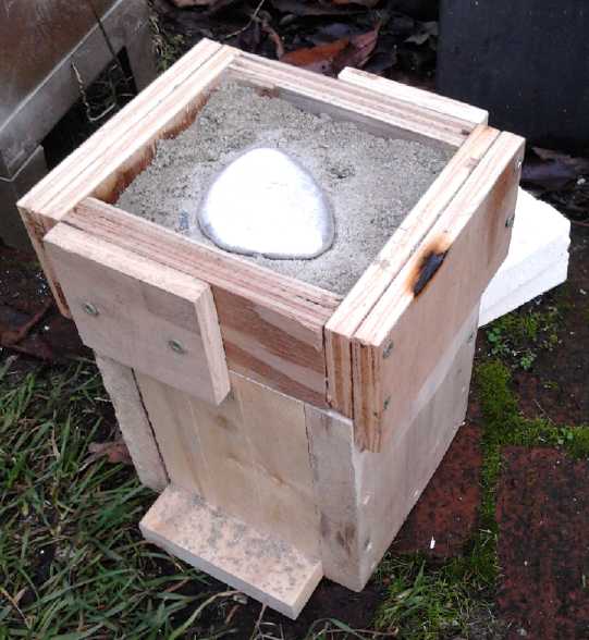
Mushroom Outboard (Outboard Motor from Scratch) Project
For the moment, this seems
to have become "The More Efficient Propeller Casting Project". I
started looking into
casting the plastic propeller blades in metal. It seems "sand casting",
as one might suspect, involves more than just sand, which would
obviously crumble. "regular" sand is mixed with very fine sand so the
pores are smaller. The simplest binder to hold the sand grains together
is bentonite clay. This is thoroughly mixed and water is added.
I thought a zinc-aluminum alloy would be easy to do
because it can be easily melted on a stove burner. I could get a good
hotplate
and do it all outdoors. A web page [www.baldwinmanufacturing.com/zinc_AL_alloy.html]
indicated
this
alloy
would
be
a
great
choice
for
more reasons than I
suspected. Another web page I mentioned before talked about the
zinc-aluminum "stovetop metalcasting". [www.gizmology.net/stovetop.htm]
On
that
site
is
the(?)
formula
for
ZA-27.
I
presume those are weight
%'s rather than volume %'s. He said:
I melted a handful of post-1982 (copper coated zinc) pennies.
Once the zinc melted, I dissolved a bit of aluminum into it, to produce
an
alloy similar to the various ZA alloys. ZA-27 (71% Zinc, 27% Aluminum,
and 2.2% Copper) is on par with cast iron for strength, but melts at a
much lower temperature and is only two-thirds as dense.
|
Gray Cast Iron |
ZA-27 |
ZA-12 |
ZA-8 |
| Compressive Yield Strength |
65,000 psi |
42,400 psi |
33,400 psi |
36,500 psi |
| Ultimate Tensile Strength |
40,000 psi |
60,900 psi |
39,900 psi |
54,200 psi |
| Density |
0.258 lb/in³ |
0.181 lb/in³ |
0.218 lb/in³ |
0.228 lb/in³ |
| Melting Point |
2795°F |
709-903°F |
711-810°F |
707-759°F |
I say the alloy I made is only similar to ZA-whatever
because I didn't measure anything - this run was just to see if it was
possible at all. To get a near perfect ZA-27 alloy would require $1.99
in post-1982 pennies, one pre-1982 penny, and 100 grams of aluminum.
This assumes that the copper on the pennies won't oxidize, which is a
stretch - to make sure there's enough copper, I'd add two pre-1982
pennies.
The pennies took about 15 minutes to melt from a cold start,
and the aluminum took perhaps another 15 minutes to dissolve. Then I
turned the burner off and let the blob cool.
I hoped I could stick the
propeller blades in a sand casting mold and simply pull them out,
leaving the cavity behind to pour molten metal into. Then I'd add a
cylinder on top as an
attachment piece, and
maybe a bit of a funnel to pour into above that.
I learned more
about "cope" and "drag" sections of a mold, slightly improving the odds
it'd work and learning vaguely known procedures. I bought sand,
fine sand and bentonite clay, the essentials for 'sand'
casting. On the 21st I made a small wooden box to pack the mix into. On
the 22nd I bought a 120V hotplate.
Then at a recycling place I got some old corroded pieces
of ship anode for a few pounds of zinc. The surface looked awful, but
inside was bright, shiny zinc. The corroded surface should just
become excess slag on top.
I could also see wanting to melt pure aluminum for casting
heatsinks, which could be easily molded. But to melt aluminum evidently
required
a lot of propane. I found a site with what look
like good instructions for making an induction heater: http://inductionheatertutorial.com/
Then I remembered my mini-kiln could melt it. I tried it
out. It took an hour - 15¢ of electricity - and I poured a little
ingot from a pottery crucible into a muffin tin. Gosh, liquid aluminum
- it actually works!
I tried to melt some in a pot on the hotplate, then on the
kitchen stove, but the thick bottomed pot turned out to be
laminated not solid. On the stove, the base layer detached and warped,
holding
the rest of the pot off the burner. Notwithstanding that the bottom of
the pot glowed dully red, none of the aluminum in it melted.
Later I watched a
youtube video of someone doing his own
first aluminum casting, and learned a few things to do and not to do,
improving my odds for success. (My wooden mold box had
to be remade.)
 When I went to
cast the prop on December 3rd, at the last moment I decided it should
be pure aluminum - wasn't zinc used as sacrificial anode? Why would I
think it would last in salt water? I pulled the zinc out of the thin
bottom stainless steel pot on the large stove burner before any melted,
and put in only aluminum - drill shavings and some fat chunks. It did
eventually melt the aluminum. But between the thin shavings of aluminum
(I had thought they'd disappear into the zinc) and I kept taking the
lid off the pot to check it, it ended up with more oxidized slag than
aluminum. Some bright aluminum was melted and would run across the
bottom of the pot under the slag if it was tipped. This demonstrated
that It Can Be Done! Then I made the fatal mistake of stirring it with
the tongs. This mixed the oxide into the liquid aluminum and everything
turned into mush that wouldn't run or pour. (Oxides melt at much higher
temperatures than pure metal.)
When I went to
cast the prop on December 3rd, at the last moment I decided it should
be pure aluminum - wasn't zinc used as sacrificial anode? Why would I
think it would last in salt water? I pulled the zinc out of the thin
bottom stainless steel pot on the large stove burner before any melted,
and put in only aluminum - drill shavings and some fat chunks. It did
eventually melt the aluminum. But between the thin shavings of aluminum
(I had thought they'd disappear into the zinc) and I kept taking the
lid off the pot to check it, it ended up with more oxidized slag than
aluminum. Some bright aluminum was melted and would run across the
bottom of the pot under the slag if it was tipped. This demonstrated
that It Can Be Done! Then I made the fatal mistake of stirring it with
the tongs. This mixed the oxide into the liquid aluminum and everything
turned into mush that wouldn't run or pour. (Oxides melt at much higher
temperatures than pure metal.)
I'll try melting
aluminum on an
electric stove again. Next time I'll pay
attention to the following points:
1. Use a big stove burner rather than a small one.
2. Use a flat bottom stainless steel pot with a lid that fits well. The
lid is all the more important as the aluminum is spread in a shallow
layer over a broad area, and thus is quite subject to oxidation.
3. Don't open the lid any more than necessary. It lets in oxygen as
well as letting heat escape. It'll probably take at least 1/2 or 3/4 of
an hour to
melt say 200 grams of aluminum, so frequent checks are pointless. (The
1500 watt mini-kiln takes an hour or more.)
4. Use big chunks of aluminum (eg, 1/4" or thicker pieces) rather than
drill shavings or thin sheet metal. The thin pieces end up mostly as
oxidized slag.
5. Don't put in borax flux. It's commonly used, but it seemed just to
be trouble both on the stove and in the kiln.
6. Put the mold close by on the stovetop, perhaps on another burner.
Lay out metal - perhaps cake pans or cookie sheets, anywhere the pot of
melted aluminum passes over. Be very careful. Always wear safety
glasses. A full face shield and leather gloves are better when you lift
the pot. Watch out your pot and lid handles aren't getting burned or
melted - especially, you wouldn't want to drop the pot. I'd much rather
do all this outdoors, but that's not where the stove is. The hotplate I
bought for that purpose
doesn't get hot enough. I don't think it has the 1000 watts it says on
it - seems more like 600 or 700. It was good for burning off some smoky
oils (or ?) on the aluminum outdoors before
bringing the pot into the kitchen, but that's all.
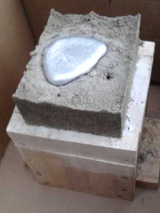
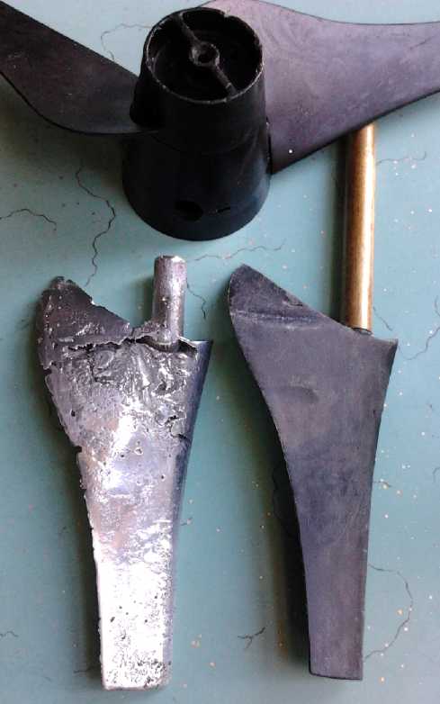
L: Removed top "cope" part of mold. (The little vent hole to the right
didn't flood with aluminum no matter how much I poured on.)
R: Breaking away the sand/clay mix
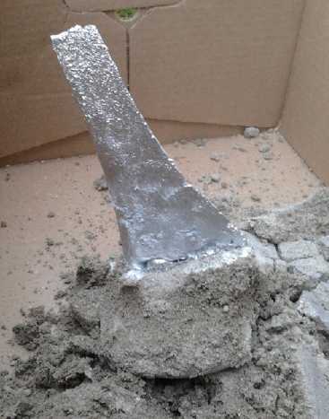
Prop freed of sand.
I poured in aluminum (melted in the kiln), to the extent
of making a big puddle of it on top. None came up out of the tiny air
vent where I expected it to. I
had an experienced friend over, who arrived just in time for the
pouring, who had a couple of misgivings about my mold and technique.
The bottom, the outer end of the blade,
filled nicely but seemed rather rough, and the tip (bottom) was quite
rough. The upper zone didn't fill completely and had some hollows and
gaps. It didn't appear to be appreciably smaller than the original part.
We discussed the probable reasons for this and what to do about them:
1. The roughness at the bottom was probably from pulling the prop out
essentially sideways to the surface. This may have roughened the sand
surface, and bits of sand probably fell into the bottom, explaining
some bottom voids. And I may not have tamped down the sand sufficiently
to press it well enough. (I did want to be able to pull out the blade!)
Other than to change the orientation of the mold entirely, I could try
oiling or greasing the surface of the prop so it (hopefully) slips out
with less disturbance, and tamping harder.
2. This is guessing... With the tiny air vent, made by strategically
poking in a wire, the aluminum quickly froze around the vent and
prevented air from coming out. This caused the aluminum to build up air
pressure and stop filling the upper area, causing the voids.
3. The aluminum may not have been hot enough, causing premature
freezing. But I'm not convinced this was the problem since I poured a
good puddle on top, and the aluminum in the crucible was still liquid
as I set it down, and after a few moments, thinking the pottery
crucible might crack from temperature strain (not to mention the wet
grass, soon burning), picked it up again with the tongs and put it back
into the kiln.
4. (I thought of this
afterwards) These factors didn't seem to completely explain it. It
wouldn't do to pour too slowly and have aluminum touching the wet clay
freezing up faster than the pouring, but think I poured too fast, and
aluminum slopped up into the air vent (and froze) before it should have
reached that height. I was surprised how fast the mold was full.
In fact, the cast blade weighed 76 grams and the puddle on top was 111
grams. The crucible full of melted chunks could easily have cast all
three blades for a prop.
5. I should have built up more of a
"funnel" in the sand at the top while forming the mold, so that the
puddle of aluminum would have more height to exert more pressure in the
top part of the mold. This is indeed the part that was full of gaps.
6. Once the prop (and a plastic funnel) were removed prior to casting,
I should have avoided disturbing the sand, as grains would tumble into
the mold. I might even turn the bottom half upside down to dump out any
loose grains.
These improvements I'll soon be trying and I'm optimistic
I can make a good propeller(s). I've thought of casting the entire prop
in one piece, but I'm not very confident about getting good results
from such a complex shape, so I think I'll stick to casting separate
blades and hub. As a bonus, the pitch will be adjustable.
I'll make a
hub with a 14mm hole and shear pin slot to fit my Honda outboard. When
I get some motor in that, I can test times, amperages and speeds
between
the shallow pitch prop, the steeper pitch prop, and this new propeller,
perhaps on a couple of different size boats. (Or maybe I can give it to
someone else to try out while I make molds to make the "mini-electric
hubcap" motor and do one to put in the Honda. Or make a whole "Mushroom
Outboard". Hmm!)
Notwithstanding that it doesn't look usable, I roughly sanded and
polished up my first ever metal casting.
CNC Farming Machine Project
A first thought for the
faming machine was to involve someone else, who has more experience
than me in both CNC and farming. He seemed less enthused than I
expected and had other ideas, citing the high cost of mechanical parts
for such an undertaking. But we might still accomplish some things
together.
The second thought was that I should do a small unit and
test things out on my own garden. And then, that an 18' wooden
extension
ladder section might make an admirable 'bridge' or gantry to go over
the
garden: Build a strong double "roof truss" shape out of more pieces of
wood. Screw it all to the inside of the rails, leaving the rails and
outside clear for the wheels
of the carriage (made of 3D printed plastic?).
This makes for a carriage that can roll from one side to
the other, with wheels on top and underneath the track so it can't come
off or tip. That should be sturdy
enough to hold a rototiller and run it back and forth through the soil.
I have two cordless lawnmowers someone gave me, and in fact three such
24 volt motors. These and optical position sensing devices might be
used in place of stepper motors for motive power. Other details are
more vague.
For rails, I considered that one could screw angle iron to
4x4 wooden beams as rails, similar to my sawmill rails, which use angle
iron and aluminum 3" x 3" tubes. (or even use my sawmill rails... hmm!)
I bought 2 wheels that run on angle iron edges. (The other side gets
plain wheels that run on the wood: only one side guides. Otherwise the
slightest misalignments between rails would cause trouble.)
This is another project for which I think flat drive belts
(with barrel shaped pulleys) would be ideal. They would have to be made
in custom lengths far longer than typical pre-made belts from a store.
This is really a traditional situation where flat belts would be chosen.
I'm trying to decide whether the gantry should operate at
a fixed height with the tools moving up and down, or should itself be
able to raise and lower. A low profile would be best for the stresses
of plowing, rototilling or raking, but passing over tall corn, or a few
other things, needs a lot of clearance... Okay, I think I just decided
the gantry needs the "Z" axis. A stepper motor at each end driving an
identical screw (like the Reprap 3D printer's Z axis) is probably a
simpler arrangement than linking two raise/lower screws mechanically
over such a long distance.
(My sawmill does 4 screws with bicycle gears and chain.) No lawnmower
motor for "Z"!
12 Volt Solid State Refrigerator Project
>It's Colder than I Thought!
The Peltier element fridge cools better than it seemed.
Belatedly
comparing the convenient multimeter probe I've been using all along, I
find its readings are too high. In a typical location it said 7º,
but two
regular thermometers in the same place said 4º and 4-1/2º.
Near the
top, it said 9 and the thermometers both said 6. Duh!
At the
floor near the ice tray, it apparently hovered
around 1 or 2. This seemed to be more in line with expectations
considering the nearby ice tray and the 3" foam insulation. Then I got
some more thermometers and started dipping them in the tray of ice and
water to calibrate them. It turned out the truth was somewhere in the
middle, about 1.5 or 2 degrees colder than the meter's reading. But
it's the difference between being nervous that things might spoil and
reasonable confidence.
It just goes to
show you shouldn't believe everything you read without verifying it,
even if it didn't come
from mainstream media. The floor near the ice tray is typically 2.5 or
3º to
4º.
Operation
I'm finding the fridge needs to run about 11 or 12 hours a
day.
Less and the ice completely melts and temperatures start to rise.
Otherwise, since the cooling is accomplished by an ice tray that's
always about 0ºc, the temperature is pretty constant, varying only
by a degree or so.
I still need to make
the smart solar control and the drain funnel for under the ice tray. I
now have what's needed and just need time to get to these details.
Use
With temperatures
inside now seeming to me to be just cold enough, I started using the
fridge for some day to day things. I put things most likely to spoil
near the ice tray end where it's coldest. Lettuce at the other end.
It's unexpectedly nice to
use. The
light 3" foam lid opens with a touch, and you can lean it open against
the wall if desired. After you lower it part way you just drop it. It
closes itself with a 'poof' of air cushion just before it hits.
Everything is very accessible
just as I'd envisioned. Since you're not reaching behind things to get
other things, the time the lid is open is usually very brief, with
little heat gain. And the cold air doesn't dive out the bottom when it
is open like with a front door fridge.
I think it's just as well I went for the simple single
hinged lid and didn't bother with multiple sections or compartment
drawers. They'd really have been superfluous as well as a nuisance.
Commercial Aerogel - Home Made Aerogel?
Aerogel at R10 is the best thermal insulation besides a
vacuum. But it hasn't been available. Now it comes in flexible matt
rolls
and in small strips for facing 2x4s in house walls, to reduce heat loss
through the wood itself. The structure of these products is to have
some
sort of solid or flexible web for strength (think perhaps of green
nylon pot scouring pads), and then fill in the space with highly
insulating but flimsy aerogel. The strips are costly; I didn't enquire
about the rolls and have apparently lost both URLs.
Then I got yet another link, to how to make aerogel: http://www.aerogel.org/?p=990
.
I don't think I'm about to follow up on aerogel insulation
myself at this point,
but it sounds exciting. An R20 fridge with 2" walls would be more
compact yet better insulated than R15 with 3" polystyrene foam. Or
larger inside with the same exterior
dimensions, eg 5.7 cubic feet instead of 4.125. A 4 or 5 amp peltier
element could replace
my ~7.2 amp one or it could run fewer hours during the day, reducing
electrical consumption.
Large NiMH Batteries - Take 3
The first basic type of large NiMH
battery, of necessity built up from small dry cells owing to
suppression
of the large sizes by corrupt interests, was soldered together cells
placed in plastic food containers. In cars, the solder joins tended to
eventually vibrate apart. The second design was to put them end to end
in PVC 1.25" (for D cells) irrigation system pipes. These work very
well, but are needlessly bulky and the sizes are often inconvenient.
The third
major variation is to 3D print custom ABS plastic cases to fit 10 D
cells (12V) in
minimal space. This of course is only possible now
that I have a 3D printer.
 I
decided to design the NiMH 12V D cells battery case
while I waited for another hour long printout. Hah! With all the
various intricate little desired features, it took the whole day. Then
it took the better part of an hour for Pronterface to make the g-code
file. Then it took 5 hours to print just one.
I
decided to design the NiMH 12V D cells battery case
while I waited for another hour long printout. Hah! With all the
various intricate little desired features, it took the whole day. Then
it took the better part of an hour for Pronterface to make the g-code
file. Then it took 5 hours to print just one.
In fact, the base layer alone took almost an hour.
Printing directly on the
glass is done very slowly in order that traces don't curl up as they
print. Since
for this object the base layers covering the entire area only make for
a solid side wall and aren't needed structurally, it would seem
reasonable to use a solid piece of plastic and glue the complex part of
the frame to it, to cut an hour off the printing time. Furthermore, the
corners warped up as it printed. If there was no bottom, might I hope
for less of that?
But it looked nice as one solid part. The top will be flat
plastic. It seemed obvious that it should be simply cut from a flat
piece. But to get the holes for the screws lined up by hand looked
tricky. It would be slow, but easier, to print even the flat tops!
...or maybe just make one flat top to use as a drill template.
 I
misjudged or mismeasured the
first one - it was 3mm too
short to hold two cells in series. The other dimensions and sizes were
perfect. Nevertheless, I found and scribbled out a half page of small
changes and
fixes. When I printed the second one, I tried stuffing some pieces of
cardboard around the partly printed object, hoping if it was kept
warmer with insulation it would warp less. A hot wire touched another
when I touched a wrong place with the cardboard. The printer instantly
stopped and started smoking. I pulled the plug. Enough of the holder
was printed to try it out and even to use it, as seen here. It seemed
only the thermistor
sensing the extruder temperature was fried, and a wire going to it, but
the printer was out of action until another could be found.
I
misjudged or mismeasured the
first one - it was 3mm too
short to hold two cells in series. The other dimensions and sizes were
perfect. Nevertheless, I found and scribbled out a half page of small
changes and
fixes. When I printed the second one, I tried stuffing some pieces of
cardboard around the partly printed object, hoping if it was kept
warmer with insulation it would warp less. A hot wire touched another
when I touched a wrong place with the cardboard. The printer instantly
stopped and started smoking. I pulled the plug. Enough of the holder
was printed to try it out and even to use it, as seen here. It seemed
only the thermistor
sensing the extruder temperature was fried, and a wire going to it, but
the printer was out of action until another could be found.
Then I read the the way to reduce or prevent warping is to
cool the bed temperature. But I've found that the white ABS
plastic,
specifically, has a tendency to break loose from the glass except at
the
highest bed temperatures. Next time I'll use another color for anything
large. Or PLA plastic. I ordered 6Kg of PLA plastic.
I'll try such battery holder design variations as mentioned when the
printer is running again.
Turquoise Battery Project
An Iron Electrode - Ni-Fe
I decided to try and
make an electrode this month after having printed several porous
plastic electrode pockets on the new 3D printer last month. I bonded a
porous plastic electrode plate cover to a solid ABS back piece to form
a plate with 4 porous ABS plastic electrode pockets, about 57 x 15 x
2.4 mm, porous only on one side. I cut out a flat copper
foil current
collector and fitted it in.
Nickel-iron
batteries keep coming up in discussions, and I decided to make an iron
electrode. I
thought of SAFT's making of highly conductive sintered copper-iron
'negodes' in the 1950s, as mentioned in Alkaline Storage Batteries.
I
didn't
have
any
fine
copper
powder,
but
I
had
monel
powder:
nickel
and
copper
alloy.
Both
elements are compatible with an iron
electrode, having lower reaction voltages.
Then again, I thought, why not make a nickel negode with
the monel
mix that I started with in 2008? To 30 grams of the monel mix I added
15g of
graphite powder to make it more conductive (15-20 ohm readings), and I
stuffed
it into the electrode, ramming it in with a little piece of plastic to
compact it. When
it was full I glued a printed plastic cover over the top. There was a
bit of a crack over each pocket, but I didn't think much about it.
The plan was simply to use it with a couple of Changhong
nickel hydroxide 'posode' plates in their NiFe cell case. It should be
1.21
volts open circuit. (= +.49 - -.72) I put it all together and filled
it.
It started out at .6 volts, but charged steadily. However, it didn't
pause long around 1.2 volts but continued up to 1.5 and started
bubbling audibly. Performance was poor and short lived. When I
disassembled the cell, I found that much of the substance of the
electrode had been percolated out of the little cracks at the top by
the bubbles. And a little powder had apparently also made it through
the perforations in the face of the pocket. Maybe I should have used a
little coarse iron oxide powder and made an iron electrode, after all.
Being stubborn, I tried again with the monel mix. This
time, I used
(nickel plated) expanded copper mesh for the current collector and
acryllic plastic for the back of the pocket plate. The powder inside
could now be seen through the back. I filled the pockets with powder,
ramming it in as
best I could, and it looked good through the plexi.
This time, I got out some
silicone RTV cement and caulked
the top shut. Now the only way out for the powder was through the
perforations or to burst something. In assembling the cell, I put a
piece of Arches 90# watercolor paper in front of the porous side -
between
it and the metal positive plate facing it.
To make a long story short, it was another failure. And on
disassembly, I found that the silicone had turned to gooey mush in the
potassium hydroxide solution.
Only later did I remember that metallic nickel is the one
metal that simply
won't oxidize in pH 14 alkaline solution, so the monel was never going
to work at that pH. Duh!
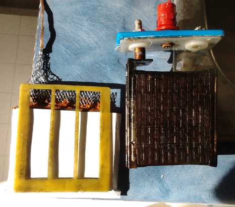
Installing with paper and plastic spacer,
with the Changhong nickel 'posodes'.
This time I went with 25g of the grainy
or 'sandy' Fe3O4 'black iron oxide' powder [pottery supply], 10g of
pure
monel powder
(not the mix) [micronmetals.com] - this time just to improve the
conductivity of the iron - and
.35g of Sb2S3 [american pyro supply]. Adding a bit of water I mixed and
pressed these together
in a press, dried the flat (but not very coherent if touched) 'cake',
then I torched it with a small propane torch for about 10 seconds to
sinter the powders together. (On the next one I torched it too long,
and there was a large patch of reddishness that would have been iron
oxidized to Fe2O3 - rust. This won't charge because it's an electrical
insulator.) Then I scraped the material (loose powder
again with a few crumbly clumps) into a small plastic container.
Resistance measurements were in
the megohms. That didn't seem very encouraging, but it wasn't open
circuit and I decided to try it anyway. (In fact, it worked better than
the original Fe 'trodes.) I wondered if the hydrogen
bubbling in the last two was caused by the graphite and didn't want to
add any this time.
I mixed in a few drops of sunlight dishsoap and water and
mixed again, then used it to refill the first electrode (which had been
removed and easily emptied by running water through it). It took
virtually all the material with hardly a gram left over.
This time, I sealed the top with sticky casting wax. Later
inspection showed this to be intact. Again
I used the art paper to mask the pocket perforations.
I calculated that
25g of Fe2O3 should have about 17 amp-hours. It turned out to be more
like .2 amp-hours - 1% utilization. This would be owing to the coarse
particle size having far less surface area for the volume than a
nano-powder.
After an hour to soak I
started charging slowly at 40mA. Since .04 * 24 = .96, that meant that
the number of days it took to charge was virtually the number of
amp-hours it had. It didn't take a day.
Yet it was soon evident that this electrode was working
better
than the previous attempts, as the voltage rise was gradual. At first,
it only
wanted to put 1/2V, 1/2A into a 1 ohm load. After a couple of hours,
that was up to 3/4 and it dropped much more slowly with the discharge.
Charging voltage rose from about 1.30V to 1.33V in that time, and the
rise or drop as the charge was put on or removed decreased from 50mV to
25mV: the resistance was dropping as the monel, somewhat oxidized by
the torching, charged back to metallic form.
But when the voltage hit 1.5 before bedtime (after 5
hours), I got nervous and took it off charge for the night. In the
morning it was 1.25 volts. I tried a load test. It put out over a volt
into a 10 ohm load (>100mA) for nearly 1/2 an hour and looked like
it would continue for hours at very gradually decreasing voltage just
under a volt. But I wanted to charge it further, not discharge it.
Probably 1.5 volts was a fine charging voltage since the theoretical
Ni-Fe is 1.43. The antimony sulfide should prevent
hydrogen gassing below maybe 1.7 volts. So I put it back on charge,
this time at 90mA until it got back up to 1.5V.
Towards the end of the day after 16 hours of charging, the
charge voltage was up to 1.6, and it would deliver over .9 amps for a
bit into 1 ohm, and almost 3 amps if momentarily short circuited. With
the
effective electrode surface/interface area being about 5.2 x 5.5 cm or
28.6 sq.cm, that was 31 mA/sq.cm current density for the 1 ohm load or
around 100 for the short. Scaled for 1/6 the interface surface area,
the short
circuit figure is better and the resistive load similar to an original
Changhong Ni-Fe cell. In evauating this, we must take into acoount that
the
electrodes are about 2mm thick instead of 1, with a current collector
of smooth, solid copper foil at the back rather than a mesh or with
holes or
coarseness to increase its surface area contact with the electrode
substance, and that it has quite low amp-hours capacity. Thus its
current performance seems considerably better than the original iron
electrodes.
I left it on charge overnight and in the morning I ran a
load test. For 1.5 hours it had a 10 ohm load. It ran most of that time
from about 1.1 volts down to .9 volts. I decreased the load to 20 ohms
and ran it another hour, after which it was again under .9 volts.
Doubtless it would have run somewhat longer at still lower voltages or
lighter loads. It was
working, but it didn't seem notably good or practical. But late in the
evening, after hours of recharging, I tried again (10 Ω) and it ran
over 1/2 hour above 1.3 volts/130mA. This was into real, practical
battery territory, and much better than the first discharge where it
sank under 1.3 volts before 2 minutes were up. It probably probably
shows why flooded batteries get cycled a few times when they're first
made.
I consider it's probably worth trying a straight monel
nickel negode again in a lower pH electrolyte just to prove it works.
Of course, the voltage will only be about -.65 volts at pH 12. If the
one I still have still doesn't work, I may try one with the pure stuff
and no graphite, and
torched to oxidize some and to fuse particles into larger
agglomerations. (With maybe a little nanocrystalline nickel oxide or
'fluffy' nickel hydroxide thrown in to up the surface area per volume.)
Nickel-iron batteries are known for their long cycle life, yet Fe3O4
gradually gets converted to Fe2O3 and the capacity gradually decreases
once there's less iron capacity than NiOOH capacity. Nickel may be .2
volts lower than iron, but it's more conductive - especially as monel
with its copper - so it loses less voltage under load. So the
difference may be less in practice than in theory. Plus the reactions
are reversable even if overdischarged, so it has indefinite life span
without loss of capacity. Still further, it's more dense than the Fe3O4
and so a lot of monel fits into a small electrode, making lots of
amp-hours in a small space.
All this wasn't getting my Mn-Mn chemie going, but it was
a simple way to assemble and test the plastic electrode construction on
single
electrodes, while trying out the copper and stibnite improvements for
Ni-Fe that nobody else was doing, just to prove the
point.
I learned the
need to seal the entire pocket plate very carefully and figured out to
seal the
top with wax but not with RTV silicone. In fact, I started to think
about new electrode and cell construction ideas and techniques.
I also used it as an opportunity to shoot some video about
battery making. Doing a video is something of a project in iteslf, but
it should really bring it to life for a lot of people who want to make
batteries but have no idea where to start or what to do - who seem to
be about where I was when I started in 2008. Unfortunately when I
"copied" the files from the camera to the PC, all it did was make an
alias/link to the camera files. But it cleverly took a long time,
longer for longer videos, to trick me into thinking the files were
being saved. Of course I didn't discover this until I went to make the
video. When I erased them off the camera to free up space, they were
gone, and I had to make another electrode and take videos all over
again. I had also planned to grab a few stills from the videos for this
newsletter, so there are few pictures here. But they're representative.
I took another look at the Fe Pourbaix diagram and noticed
that contrary to my previous belief, it in fact looks compatible with a
lower pH electrolyte. At pH 12 it's about -.82 volts. Since nickel
oxyhydroxide goes up to about +.65 at that pH, cell voltage for
Ni-Fe/pH 12 should be a little bit higher than in KOH/pH 14.
Next Steps?
The next 'negode' with Fe3O4 nano powders wasn't
successful. I tried painting the face with egg albumin, which I then
boiled, but the KOH electrolyte dissolved it, allowing powder to leak
out. Furthermore, the dissolved albumin caused rapid self discharge
even after briefly rinsing the
electrodes, putting paper in front of the iron one to catch leaking
powder, and replacing the electrolyte.
Either I need to get a 3D printer that does finer traces
and smaller pores, or stick with grainy powders, or find some other way
to make electrodes. Camosun's printer makes considerably finer pores,
but I certainly can't afford their prices. I've decided to stick with
porous plastic pocket electrodes for now since so many other
constructions I've
tried haven't worked, and with the grainy Fe powder for now, but to
crush it further with a hammer. It still wouldn't be nano and shouldn't
leak out much. Presently the pottery supply has only nano "black iron
oxide", but "granular magnetite" is close enough the same thing. I hope.
With the one working Fe 'negode' to test with, next is a
'posode' with a graphite current collector to work in the lower pH
electrolyte. Once both sides are working properly, I can work on
getting best amp-hours and performance, and then try out manganese
electrodes both '+' and '-'.
Posode Current Collectors: "Flexible Graphite Foil"!
I saw a youtube video on "Aquion" batteries and looked up
the site. To my surprise they had
a paper to download that described how their batteries worked. Their
chemistry (manganese, salt) and
philosophy has quite a bit in common with mine, tho their route was
somewhat different. For me the chemistry was mostly of passing
interest, but a term used perked my interest: Graphite Foil
current collectors. It turned out to be something the "Graphite Store"
website, the place I looked a couple of years ago for a carbon based
current collector solution, simply didn't have. But it's the stuff
people evidently have been using in various batteries (including the
very first design I ever looked at), that I could never find. As is
often the case, I just didn't know the name to look it up or ask for it.
And someone may well sell it for some unrelated purpose
(eg as
"gasket material") locally, but again I don't know where to look or who
to
ask. But I went on line and found it seems to be quite common. I
ordered
a roll of .020" x 5" x 108' of "flexible graphite" 'gasket material'
from www.minsealorder.com -
about
50$ list for 324 electrode plates worth.
Unless it has some problem (like the "expanded graphite"
gradually swelling up and decreasing in surface conductivity), it'll be
much better. Since this is what others seem to be using it is likely to
work fine, in which case all my work with carbon rods from dry cells,
carbon fiber, 'grafpoxy' and other graphitic materials may have been a
dead end, and added a year or two to the Turquoise Battery project
as a whole.
"Practical" Battery Production? (meaning: ability to make enough
for an EV or
solar installation in a reasonable time, instead of hours to make one
cell)
Finding my 3D printer's resolution is rather coarse for what I bought
it for - porous battery electrode pockets - I'm starting to think again
of other means of electrode and battery production. Squashing an
electrode flat from a face takes many tons of pressure. If the
electrode is very big at all, a 12 ton hydraulic press is inadequate.
Earlier efforts to compact the material from one end
resulted in mashing the mesh current collectors. Yet it seemed to work
reasonably well in a recent pocket electrode with copper mesh. Plus, a
sheet copper current collector seems to work well enough (so other
sheets should too, including 'flexible graphite' sheets).
(Potentially, small holes could also be punched in such sheets to
increase contact area.)
So then, a tall, narrow, well polished steel box as an
'electrode die',
with a funnel attached to hold the material, and a matching thin (~3mm)
punch could use a much smaller press such as the book press to compact
a solid electrode, in several plunges with more material dropping in
each time. The (bottomless) die would then be raised and the electrode
extruded down out of it. Any desired aspects of this could be
automated. The briquette can then be dried and torched whole, instead
of having to torch it and then crumble it and feed it into a plastic
electrode
pocket.
Next, a piece of plastic would be 3D printed that is
exactly
sized to the width of the cell cavity, perhaps a slightly widened
section with slots in the cell walls to accommodate it. Tho thin, this
is porous and it has channels to allow bubbles to rise to the surface.
And it has a lip around the edge. When a piece of paper is pushed
against it, the lip ensures there are no gaps around the edges. (With a
finer resolution of printer to make finer pores, perhaps the paper
might
be dispensed with.)
The cell is constructed: 1, 2. metal current collector,
pressed with negode, 3. a sheet of watercolor paper, 4. the plastic
divider, 5. a sheet of watercolor paper, and 6, 7. the posode pressed
with the graphite current collector. Since the thickness of each piece
can be carefully controlled, this whole assembly is made to fit exactly
into the cell cavity, and it is put together and pushed in from the
top. Wax is dripped in to cover the tops of the electrodes but not the
center vents.
It's a liquid filled battery, but there's very little
liquid in it except whatever reservoir is added above the tops of the
electrodes.
http://www.TurquoiseEnergy.com
Victoria BC