Turquoise
Energy Ltd. News #59
Victoria BC
Copyright 2013 Craig Carmichael - January 4th, 2013
www.TurquoiseEnergy.com
= www.ElectricHubcap.com
= www.ElectricWeel.com = www.MushroomOutboard.com
Features: New: The Mini Electric Hubcap
Motor
(see "Motor Systems")
Month In Brief
(Project Summaries... and little things not warranting separate
report headings)
- Mini motor, bike rim motor, 3D printing, battery construction, Simple
Ocean
Wave Power!
5 Years In Review (Miscellaneous
topics
and editorial comments)
- 5 years of green energy projects - The coming New Epoch.
Electric Hubcap Motor Systems
* New 6 coils "Mini Electric Hubcap" motor: 24V, 3KW,
0-3000 RPM, 9" O.D. x 4", ~17 pounds.
* Ceramic "Cup Magnets": Cheaper strong motor magnets?, Magnets for
bike "wheel arc" motors?
* Start of arc motor for bicycle
Planetary Gear Torque Converter &
Ultra-Efficient Vehicle Transmission
Project
* Torque Tests (Electric Hubcap is about 1.5 foot-pounds per 10 Amps.)
- Divide by Zero Error?
* An ideal flat drive belt?: Polypropylene or Nylon
Strapping
* Clutch system for Sprint: idler/belt tension wheel (of cast
aluminum), clutch pedal...
Turquoise Battery Project
* Conductive Porous pocket electrode plates
* Filler/airlock cap & complete Mn-Fe test cell
No Project Reports on: DSSC
solar cells, LED Lighting, Pulsejet steel
plate cutter, Magnetic Heat Pumping, Magnetic Motion Machine, Large
format NiMH batteries - take 3, Mushroom Outboard, CNC Farming Machine
(but see 'month in
brief'), Superinsulated 12VDC Peltier element fridge (finished except
for smart solar control... and stocked with food). In future 'Electric
Weel'
motor will be covered in "Electric Hubcap Motor Systems"
Newsletters
Index/Highlights: http://www.TurquoiseEnergy.com/news/index.html
Construction Manuals and information:
-
Electric Hubcap Motor - Turquoise Motor
Controller - 36 Volt Electric
Fan-Heater
- Nanocrystalline glaze to enhance Solar
Cell performance - Ersatz 'powder coating' home process for
protecting/painting metal
Products Catalog:
- Electric Hubcap Motor Kit
- Sodium Sulfate - Lead-Acid battery longevity/renewal
- NiMH Handy Battery Sticks, Dry Cells
- LED Light Fixtures
Motor Building
Workshops
...all at: http://www.TurquoiseEnergy.com/
(orders: e-mail craig@saers.com)
December in Brief
Christmas season occupied a notable fraction of the month.
Still, a new second type of motor, the "Mini Electric Hubcap", is well
under way and a few other things are inching ahead.
Electric Hubcap & Torque
Converter Torque Test
I ran some tests on the PGTC on the bench the 10th. To my
satisfaction, these happened to disclose that the Electric Hubcap motor
was putting out about 10 foot-pounds of torque for an input of maybe
60-70 amps, or 1.4 to 1.7 foot-pounds per 10 amps. Previously I'd been
guessing it was around 1 per 10.
The converter, however, only put out about 10 foot-pounds
with the slipping pulley system. In fact, it did better with about 22
from the locked rotor of the motor pulsed to full power. (This figure
divided by the gear ratio of about 2.2 to 1 gave the 10 for the motor.)
This seemed to fly in the face of the theory of operation
of the converter. I wondered if maybe great ratios were useless if the
car was stopped, since one was dividing by zero. It might work as
expected
once in motion - but it had to get into motion first. The way to do
that seemed to be the flat belt drive with an idler wheel to apply
tension to the belt: ie, with a clutch. I made the idler wheel and
bought a clutch pedal, but have not yet installed either.
Rim-Arc Bicycle Motor; small Electric Hubcap Motor
I decided that if I wasn't going to make the "Mini
Electric Hubcap" motor or the bicycle rim
motor
right away, I'd at least get all the parts lined up. Since I already
had a
steel wheel ring, coils, motor controllers, magnet sensors and
connectors, what was missing (besides minor hardware bits) that I'd
have to purchase boiled down to appropriate magnets. (Missing
components that I'll have to make: mold for arc stator, appropriate
shape magnet sensor board, various mountings and fittings.) It would
take
quite a few magnets to go around the big ring, which was 21.6875" O.D.
and 19" I.D., with the median circumference of the ring thus being
63.7".
After some figuring, 16 magnets would be just under 4"
apart. Since two magnet poles span 3 phases, that would mean the coils
would be 2.65" apart. 2"x1" magnets give the most bang for the buck,
but it's 1/2" of room for the usual 1/2" thickness is cutting the space
too fine. 3/8" should make it as long as the wheel is adjusted
properly, so 2" x 1" x 3/8" magnets. To ensure the coils don't hit the
magnets, I could put in a bearing that would ride on the ring or on the
wheel rim if the coils would otherwise contact.
Then I discovered ceramic "cup magnets" while I was on the
site. The 2.6" diameter ones might work out well for the bicycle wheels
for 1/2 the price of neos, and they'd be easier to use and mount. There
were also 2" cup magnets, and I thought they might be
good for Electric Hubcap motors. The motor might have a plastic rotor
instead of steel, since the cup magnets are already in steel cups that
complete their magnetic circuit without external steel.
I also decided that I would do the smaller 24V, 2.5 to 3
KW, 3000 RPM
"Mini Electric Hubcap" motor and I proceeded ordering parts for both
ideas. That
would make a motor that would fit in the Honda outboard leg, and I'm
pretty sure others will have many good uses for them as well. It's an
especially useful size and voltage for
marine transport that I suspect isn't
commonly found. It could also be used as a 12 steps per rotation
stepper motor for the CNC farming machine, with enough power to till
the soil.
After receiving most of the parts, I decided not to wait
for spring after all. I
made molds and drill jigs and made two complete "Mini Electric Hubcap"
motor bodies. I would have completed and tried out one, but I didn't
yet have the bearings (just one sample), and the waterjet place hadn't
yet cut my 7.5" steel magnet rotors. I also have yet to make a magnet
sensor board.
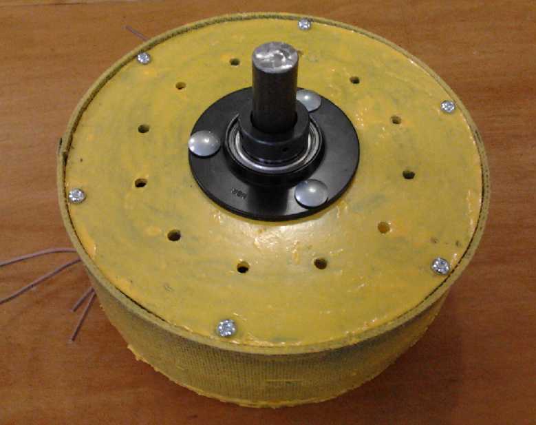
"Mini Electric Hubcap" BLDC motor test fit
24 V, 127 A = 3 KW, 9" O.D. x 4", 0-3000 RPM
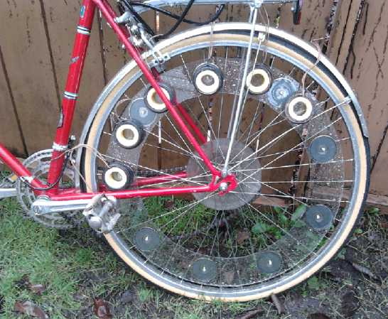
I started in on the bike wheel too. I didn't use the steel
ring and supermagnets. Instead I used the 2.6" cup magnets behind a
1/8" lexan sheet, to be attached with recessed flat heat bolts. If the
coils touched the wheel on bumps or from bad adjustment, they'd contact
the smooth lexan sheet instead of a row of lumpy magnets.
A unique feature of this motor is six unipolar permanent
magnets. Since the cup magnets are (mostly) all polarized in the same
direction, and since spoke spacings on the wheel proved contrary, the
south poles are skipped. This would appear to require optical rotation
sensors instead of magnet polarity switches. I tried several
arrangements with various problems, and I ended up with one with just 6
magnets, all of one polarity, and the 6 coils at 20º spacings. I
hope it provides enough torque not to need revisions.
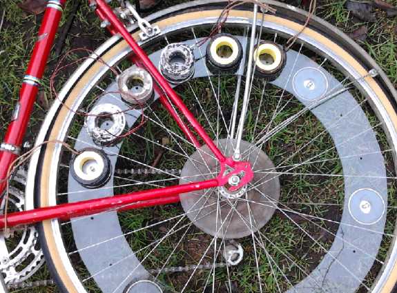
Magnet ring and coils for 27"x1.25" bike wheel - will probably fit many
bike wheels.
The coils will mount in an arc shaped housing with an indent for the
bike frame in the middle.
On the 12th the awaited thermistors came and I fixed the
3D printer the next day. Attempts to print things didn't go well. The
PLA plastic is easier to work with than ABS, melting at a lower
temperature, and I broke open my shipment of it, which I'd simply
placed in its carton in the closet. It didn't seem to print well, and
suddenly suspicious I found that all 6 spools were ABS instead of PLA.
I probably went to the wrong page when I ordered. The pictures of
spools of plastic look alike, and late in the evening one familiar TLA*
looks much the
same as another.
The ABS, D cell battery cases kept on warping. They'll
probably work in PLA. And trying to print porous battery electrode
pockets with smaller pores was making non-porous surfaces instead. Then
I thought I'd try a NiMH battery case with no bottom. If that
worked without warping, I'd glue a piece of stock ABS onto the bottom,
and it would cut an hour off the print time anyway. It didn't work. It
warped and the whole piece came loose from the bed while printing.
I decided the cases would have to wait for PLA plastic,
and it didn't arrive by month's end. The conductive ABS clogged up the
print head, and I decided I'd have to really want it before I'd use it
again. A new reason I would really want it: Hey! it's carbon fiber!
That makes it strong, desirable material for mechanical parts such as
gears and flat belt pulleys.
* TLA: Three Letter Acronym
CNC Gardening/Farming Machine
The CNC farming machine continues to evolve in my head.
Using polypropylene strapping as flat drive belts makes extremely long
drive belts seem feasible. In addition to providing a secure position
reference to the control computer, this would potentially allow the
main gantry moving motor(s) to mount in a fixed location at one end of
the
track, and the carriage moving motor to be fixed on the gantry instead
of placing it on the carriage, reducing the extent of long, flexing
wiring.
The "Mini Electric Hubcap" BLDC motor (or even the big
one) could be used as a
very large stepper motor. The magnet position sensors provide for exact
stepping to desired position, and at over 3 HP it has the power to plow
or till a field. The fact that it's 3 phase with 12 steps per rotation
can be accommodated in the hardware and software drivers. That should
beat the
cordless 1/3(?) HP brushed lawnmower motors all to pieces.
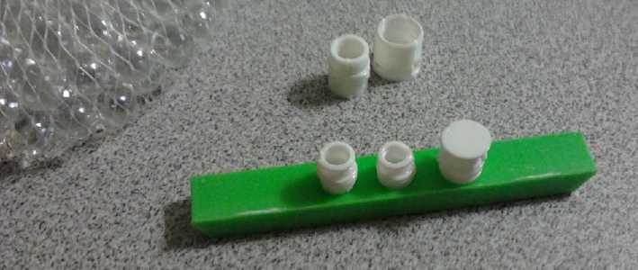
Battery Construction
After printing some conductive porous pocket plates, and
then some filler/airlock battery caps and finding some glass balls to
be the airlocks, I printed some parts and made a test cell. It's
getting close to a design or two that can be produced, perhaps
relatively easily. The
test cell has started with the Fe negode from last month, and a new Mn
(permanganate) posode. But the Mn electrode has low conductivity (not
enough graphite!) and will be improved or exchanged for another, and
then other minus sides - Zn and Mn - will be tried with a working plus.
(I'll probably also try a vanadium pentoxide posode with a Mn minus for
a lark sometime, to see a cell that should be well over 2.5 volts.)
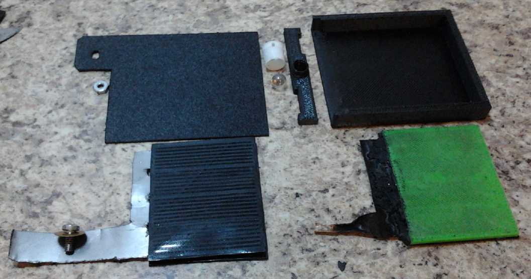
The components of the battery cell.
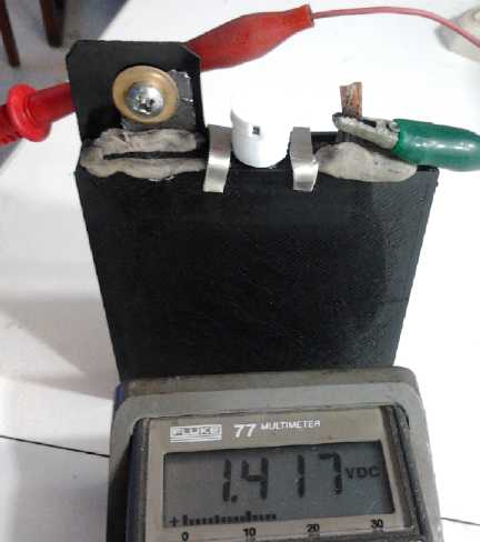
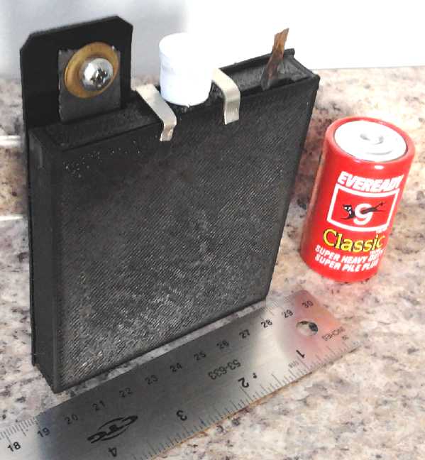
The working battery.
Since this one is for testing electrodes, I didn't glue the top on, or
seal the terminals with heat glue.
Simple! Ocean Wave Power Device
A friend sent me a link to a web/PDF book on free energy
devices: http://www.free-energy-info.co.uk/
. After Christmas I had a brief look. It has a wide variety of
interesting devices
including magnetic and coil energy machines, but one that struck me
almost instantly was
a simple device for extracting ocean wave power:
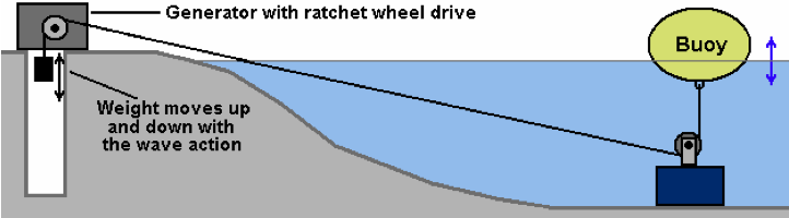
At a glance the diagram looks "Mickey Mouse" - a toy for a
theoretical demo. But the simplicity is pure genius! Each feature is
the essence of the matter boiled down to the simplest and most
effective form. First and foremost, a lightweight buoy with a concrete
anchor, pulley and rope are
the only pieces in
the corrosive salt water environment. (There would be a pulley on a
swivel at both ends of course.) Simple, robust parts can more easily be
designed
to withstand storms than more complex things. A foam filled float that
will submerge without lifting its anchor is hardly going to be damaged
by surging waves. The rest of the structure is on solid ground - and
thus isn't rocking adversely in the same waves the power capture float
is in. This makes for the best leverage on the waves.
Next, something has to
run from the device in the water to shore, and rope is cheap
compared to heavy wire cable, especially that made for sub-sea use.
Thus floats can be placed in deeper water farther from shore without
much extra cost. Waves have more power in deeper water before they
incur bottom friction. And they're 'more solid' in the deep before they
start to break.
Third, forget the hole in the ground: the shore
installation would be a tall, enclosed structure. (at least one tall
pole is
needed for the high voltage lines leading away anyway.) The weights
would have a
long range over which they could rise and fall from the overhead drive
shaft to the ground, so tides would be no problem. In fact, differing
tide levels will even out the back and forth pulley wear over different
parts of the rope.
Finally, the entire system uses just one large generator
and one-way "transmission" that ties
it to all the floats. Instead of a unit associated with each float,
there's just one large mechanism to be mounted, wired and
maintained. This is a huge economy. (Note: The 'ratchet drives' shaft
will have to be
considerably geared up to turn a generator at speeds it'll make power
at. It might well take a two-stage increase. Here again the nearly 99%
efficient flat belt drive with plastic pulleys would doubtless make the
best speed converter with the least friction.)
Naturally one would employ a set of floats offset
diagonally from each other and at different distances out to sea,
spanning at least a typical wave length, so that the drive shaft is
being continually driven by fresh waves. A flywheel could help smooth
out
bumps. The maximum power harnessed depends on the volume of the
flotation and the weight of the hanging weights. One person says
sizing the components to resonate with the typical wave frequency will
increase power gained. (I'm somewhat skeptical that the effect will be
pronounced owing to the damping caused by extracting the power, but
even a few percent improvement is an improvement.) My own improvement
idea would be what I've proposed before: longer, thinner, shallower
floats - oval shaped pipes perhaps - that would line up with the waves
to
optimally catch the topmost crests of the most linear meters of
wavefront. (Think of the buoy in
the diagram as being the cross section of a piece of pipe maybe 3 or 4
times as long as the width.)
Any system has its disadvantages as well as advantages.
The ropes would be going back and forth (well) overhead across the
beach instead of having buried electrical cables, and the tall base
structure wouldn't be intrinsically attractive except in the eyes of
the builders. (If the cables are too low overhead at the bottom of the
beach, an
additional tower will be needed down there to raise them, or the main
tower could be placed there.) But most any wave power system is going
to have some basic similarities -
floating components to transfer the power of the waves to a mechanical
or hydraulic system, some sort of shore installation, and power lines
heading for the grid somewhere.
I would think such simple installations could be created
for a
small fraction of the cost of either hydro dams or wind power, and
could indeed satisfy the bulk of our energy needs here
on Vancouver Island. A test installation should surely be tried out.
I'm not favorably situated to attempt the experiment.
5 Years In Review
Incidental news, editorial opinions
When I decided in
January 2008 to try to put a motor or motors on one or more wheels in
my car and make homemade batteries to run them, I little dreamed that 5
years later I still wouldn't have electrically hybridized cars on the
street and still wouldn't be producing batteries. No doubt it's just as
well we don't know such things in advance, or it would be very tempting
never to attempt them. However, ignoring or pushing aside good ideas
isn't the path to progress.
The 36V, 4.6 KW
motors and controllers have evolved into very good equipment, and I've
started a new smaller size 24 volt, 3KW motor that should be running
pretty soon and should prove useful for various applications.
The 2 volt Mn-Mn moderately alkaline battery chemistry has
been proven this year, and just as importantly, means for producing
working battery cells are finally being created, with parts made by 3D
printer such as
airlock caps playing a leading role. Along the way I
discovered sodium sulfate is a good renewer for supposedly 'spent'
lead-acid batteries, that 3 or more banks of 10 Ni-MH D cells make
fabulous, long life car starter batteries, and I devised several ways
to mount these D cells to make them into practical 12 volt batteries.
The fact that a motor that would fit on a wheel couldn't
have both enough torque to get a car moving and reasonable RPM at
highway speeds led to the variable torque converter project, which,
even up until now with the very promising planetary gear torque
converter system, has been the main hold up to getting
'ultra-efficient'
electric car drives onto the street for 3-1/2 years.
And a number of 'incidental' projects have been
undertaken. Some are more along the lines of research, such as the
paramagnetic coil coatings, nanocrystalline titanium dioxide
borosilicate glass to improve solar collector efficiency, and
experiments with diverse magnetic machine ideas besides regular motors,
including magnetic variable torque converters, magnetic "free energy"
designs, magnetic spacecraft propulsion and magnetic heat pumping.
Others projects are more of the nature of applying proven ideas to
development of novel new products, such as the low voltage solar energy
wiring and applicances (12 volt LED lights, 12 volt solid state
refrigerator, CAT standard 12 volt plugs & sockets...), various
applications for the motors and controllers, and the new Peltier
element heat pump. It was discovering the fabulous energy saving
potential of LED lighting that also got me started on installing a
solar PV system and trying to create better parts and equipment for
doing so.
2012 has seen a great increase in the variety of projects,
branching out from the electric transport and battery storage ideas
into other newly developing areas of energy production, conversion and
consumption.
At the start of 2008 I had just four projects: the wave
power machine, a car wheel motor, a motor controller for that, and to
make some sort of battery. I abandoned the wave power early on (which
is well since I've just run across a much better design), leaving just
the three related to electric transport.
A big reason progress is so slow on each of my projects
now is that I now have over a dozen "active" projects.
Of 30
days in a month, I try to do other things Sundays, and there are days
when various things just need attending. Shopping for various often
obscure parts and supplies for each project occupies considerable time.
Then I spend considerable time writing these
newsletters to pass on whatever value and inspiration my ideas and work
may have for others. This not only
takes time but also leads to dangerous new thoughts resulting in more
projects and sub-projects related to a main project... like magnet
machines... solar installations and low voltage
wiring... solid state fridges... light rail vehicles... and CNC
gardening machines.
So for actual work, that leaves maybe a day or a day and a half per
project per month, on average. Sometimes no matter what I'm doing, I
feel like I'm shirking something else. But it's not possible to work on
two things at once, and lately I've grown able to put that feeling
aside and concentrate on whatever I'm doing, without asking myself if
it's the best thing I could be doing once I've chosen something.
I'd like to target specific things and finish
them, but so
many projects seem so valuable or seem to have such technological or
commercial potential that it's hard to let anything lapse for too long.
While the value of putting an ultra-efficient electric car
or (especially) hybrid on the street to show the way can hardly be
overestimated, I
suspect that the best markets for small scale production are really
marine,
and gardening
and farming, rather
than things for cars and solar home equipment. But batteries have
rather universal application, and electric bikes appear to be rising in
popularity. This says that the
Mini Electric Hubcap motor,
the Mushroom Outboard and the CNC Farming Machine are probably the
things
to concentrate on. Then if I'm
making money,
perhaps I can
hire people to work on some of the other things. But naturally I want
to get the Sprint car
going and
do the solar DC wiring in my house, and the CAT plugs and sockets are
about ready to sell - after some more "beta testing", which ties into
my DC house wiring... when I find some time to continue it!
End of the Age - More on Banking
As time passes, I'm becoming aware that the
world is changing forever, at a rapidly accelerating pace. We have
arrived at the end of an age
and are poised at the start of the next. The transition will be
attended by fierce storms and upheavals, manmade and natural, some of
which are already starting to break. The "status quo" attempt to
maintain their positions while a few of the most powerful reprobates,
having attained the choice positions of economic and political power,
seek to enslave the whole of humanity and to destroy vast numbers of
people. Much of humanity sits about, oblivious - and many are deceived
by clever manipulations, or are even deprived of their health and
clearheaded thinking by the heinous food and drug poisons being foisted
on us by the
corrupt. But others in growing numbers are starting to perceive how
misled and enslaved we've been for so long, and are surging forward to
change the ways the world works. And some of the corrupted are
considering their value systems and changing their minds. These new
energies, coming up against the
lingering but ensconced contrary forces of opposition to change, are
bound to brew great storms.
When I started my green energy projects in 2006 with ocean
wave power, I knew little of all the adverse forces hiding in the
background
of what
I'd been taught was an orderly and well run society. But manipulations
that
have pulled the wool over peoples' eyes and been forgotten in past
times are becoming
obvious and persistent on the internet. It seemed things were
dysfunctional, but I
didn't really understand that individuals in strong positions actively
and effectively worked to prevent progress. By the time I'd got very
far on
the car
hybridizing as perhaps one of Canada's most accomplished inventors, and
even my member of parliament could find me no workable
funding source or program, I began to understand that no specific
useful help would be available from any quarter of the 'mainstream'
socio-economic-political system regardless of anything I accomplished
or proved - and that it was best to stay off the radar screens of the
wrong people.
But this long protracted situation is changing. No one
will take unhealthy notice of a new electric car system when big
automakers are themselves starting to make electric cars, and I should
think that what I'm doing is going to fit right in to the beginnings of
the new economy that will inevitably take shape when the storm clouds
lift.
As an addendum to last month's "American financial
history" mostly from the
early 1800's, I've found out a few more things. President John Adams
had a similar view to Jefferson and to Jackson, that there were two
ways to conquer a people: with armies or with debt. And I saw on
youtube that the bankers in Europe were horrified by Jackson's
nationalizing the printing of money, because they couldn't control it
and charge interest on it. And, that in 1906-07 the bankers
orchestrated a financial crisis, and it was this that led to the
"solution" that they proposed and that was adopted, the US federal
reserve act of 1913. Woodrow Wilson, after much political pressure,
signed it
in spite of evidently recognizing that it was a death warrant for
national liberty. Apparently he didn't have Jackson's fortitude. It
took 80 years, but the bankers got their way again. Since then, somehow
this pyramid scheme "financial system" has been forced on the whole
world - and sucked in the national wealth of many nations.
In the USA, congressman Ron Paul has been warning for over
a decade about the housing bubble that was being built up, the housing
bubble collapse, and the coming collapse of America and its "almighty
buck". He was laughed at and paid no more attention than Winston
Churchill during the 1930's, when he repeatedly warned parliament that
unless prudent
action was taken in good time, Germany was going to start another world
war.
The system almost
collapsed in 2008, and a worldwide collapse seems inevitable, most
likely this year, with far reaching consequences... including
freeing humanity from the clutches of all the dying, corrupt
institutions it fostered. That will prepare the way for the new age, to
be built on sustainable foundations.
"But you should be wise regarding the ripening of an age; you
should be
alert to discern the signs of the times. You know when the fig tree
shows its tender branches and puts forth its leaves that summer is
near. Likewise, when the world has passed through the long winter of
material-mindedness and you discern the coming of the spiritual
springtime
of a new dispensation,
should you know that the summertime of a new visitation draws near." -
Jesus
Electric
Hubcap Motor Systems
Mini-Electric Hubcap Motors
Along with rim-arc motors for bicycles, I decided to
proceed with 6 coil regular round "Mini" motors as an expansion of the
Electric Hubcap product line next spring and summer. I first decided to
order
parts to have them on hand for later... but when I'd collected enough I
decided
to start now and not wait for spring.
The Mini Hubcap uses a nominal 24 volts instead of 36, and
6 of the
same coils instead of 9, and the same motor controller with the same
nominal 127 amps max,
making it 3 KW. (Or it could be made 36V, 83A.) RPM is nominally 0-3000
instead of 0-2000.
Electromagnetically considered they are thus identical, with linear
magnet speeds similar to the existing Electric Hubcap motors. Barring
some novel manifestation of Murphy's law, there's no reason to think
they won't work flawlessly and virtually the same except for the RPM
range, at 2/3 the voltage (or 2/3 the current - and hence 2/3 the power
either way), which can only be
easier on the motor controllers.
Dimensions
are 9.25" O.D. and
about 4" long, with 7.5" rotors having 4 magnet poles (with eight
1"x2"x.375" magnets NNSSNNSS). I picked 7/8" shaft size as being
sufficient but not needlessly heavy (based simply on shaft sizes of
other multi-horsepower motors I'm familiar with), and I found nice
flange bearings
for that size at Princess Auto, which seemed to simplify the question
of how to
mount bearings and incidentally of how to adjust the shaft position and
the magnet gap: It can be done from the outside with the motor
assembled, with clamping pieces that come with the bearings. The
bearings in these flanges seem too wide to be roller bearings - they're
probably a better type, ie, roller or needle bearings. That's good
since
this isn't just some 1/4 horse motor.
A 24 volt supply is very attractive for battery
applications. It's definitely not going to electrocute anyone, and two
batteries (with two 12V chargers) makes the system an easy initial
hookup and capital outlay to get started and test.
I bought a length of 4140 HTSR (relatively hard tool
steel, heat treated, stress relieved) 7/8" machine shaft at Metal
Supermarket, and a lighter taper lock coupling than SD ("HX") at
Princess Auto. I took the plan and the HX
bushing to Island Waterjet to have the rotors cut. At the same time, by
planning in advance, motor face mounting flanges will be easily cut
from the pieces left over, as the outside curve of the rotor is also
the
ideal inside curve of the flange.
I ordered a batch of slightly thinner supermagnets, 1" x
2" x .375" instead of 1" x 2" x .5". I've long suspected those will
work just as well, with a slightly smaller magnetic gap and a thinner
rotor (.25"), and will make the motors about 1/4" thinner overall, or
even
5/16". At any rate, I was sure they were good enough for the bicycle
and smaller motors, and I suspect they'd be better for the big "Weel"
motor too, assuming I get back to that sometime. (I may also have some
new ideas for making the Weel's stator body in arc-pieces when I've
done a rim-arc bike motor or two. I'm increasingly apprehensive about
the plywood stator, which has no coil button moldings, which is one
reason I haven't gone any further on putting it together.)
While on the site, I looked around and found some ceramic
"cup magnets". The 2.6" diameter cup magnets had a listed pull of 50
pounds, which was far more than non-cupped ceramic magnets and only 10
pounds less than the supermagnets, and they were 1/2 the price. They
seemed like a good size for the bicycle wheel motors as they'd just fit
between the spokes. 2" diameter ones had 40 pounds of pull, which,
while quite a reduction from about 70 pounds with my usual 1" x 2" x
.5" supermagnets, still seemed like enough to make a good motor from
(with a thinner magnet gap) if the depth of field isn't ridiculously
thin.
A rotor might be made of cup magnets sandwiched between
two sheets of lexan instead of steel, which would make the motor both
lighter and cheaper to make.
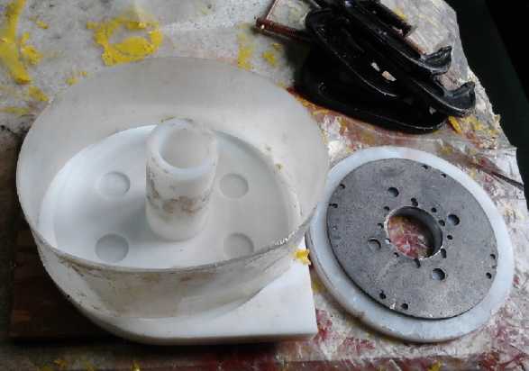
Mini Electric Hubcap motor body parts mold - ready to stuff.
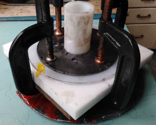
The C-clamped mold pressed the PP cloth and epoxy together while the
epoxy sets.
Here it's just come out of the oven, ready to release the new part.
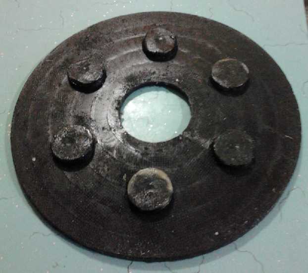 On the 15th I
routered out a mold base with the CNC
drill-router, then a top. Everything considered, it seemed that the one
mold was good enough for all three flat body pieces. The only notable
oddity would be having coil buttons on the rotor cover. I might even
minimize them by filling the button holes with... something.
On the 15th I
routered out a mold base with the CNC
drill-router, then a top. Everything considered, it seemed that the one
mold was good enough for all three flat body pieces. The only notable
oddity would be having coil buttons on the rotor cover. I might even
minimize them by filling the button holes with... something.
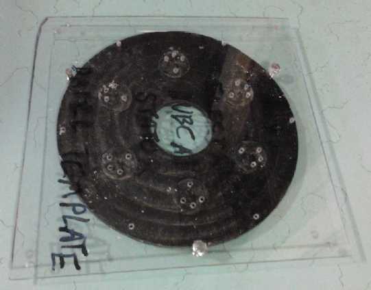
The same evening I did up the main g-code sequence for the
hole drilling template. Naturally, since I was using the same coils and
basic design, I was able to borrow heavily from the original Electric
Hubcap
motor spreadsheet and G-code design files.
Finally, before I went to bed I cast the first body piece.
I used 65g of polypropylene ("landscaping") cloth and 240g of epoxy
resin. I
departed from my usual technique when I found I had poured too much of
the resin too early and didn't have enough left for the remaining
cloth. So I kneaded it by hand. This mixing led to better overall
wetting of the fabric than I usually got, and tangled all the ripped up
scraps of cloth together better, which could only make the piece
stronger. The
result was good. I had vinyl one-use gloves this time, and unlike latex
they held together well in the gooey epoxy. The next morning I did
another one. They were both
hard to remove from the mold - then I remembered I usually wax the
molds. The next one I waxed... and then decided that having clean,
unwaxy parts was better than ease of removal.
I decided taller buttons would be better - the coil bolts
would screw into more thickness of plastic and hence be less likely to
strip. It's a bit of a conundrum that nuts up there would stick up into
the rotor compartment, or if flathead bolts put in from that side came
loose, they'd stick up, and either way, the metal would hit the rotor
magnets and chew things up as they spun by. So only the plastic is
available to screw into.
But once a part is removed from the CNC
machine, that's usually it - they can't be properly lined up again. But
I remembered that when I did the top mold, I had moved the "home"
position of the machine exactly .10" to the left, and it had finished
in home position... so this could be reversed and the previous 'home'
for the base mold regained. Then, if the mold was screwed back
down in the same screw holes, it should be in exactly the same position
it was before. I
decided to gamble on it. The buttons went from just 1/8" deep to 5/16",
and the position turned out to be only about .01 or .02" off.
I cast the third flat piece, and the coils pushed on with,
to say the least, no play to spare, since the buttons, already
carefully sized, were now just that bit bigger.
By the end of the 16th, just two days into the project,
the body assembly only needed the rotor rim... perhaps that could be
done without a mold, or with just a disk mold piece on the inside? Then
I thought to just staple a piece of polyethylene into the shape of a
ring the correct diameter - the body piece would keep it round.
 What else? The hole template wasn't made and the body
holes drilled. How to mount the bearings was unclear after it was found
the flanges wouldn't fit, the rotors were still waiting for Victoria
Waterjet to cut them, and a magnet sensor board needed to be designed.
What else? The hole template wasn't made and the body
holes drilled. How to mount the bearings was unclear after it was found
the flanges wouldn't fit, the rotors were still waiting for Victoria
Waterjet to cut them, and a magnet sensor board needed to be designed.
On the 17th I made the trek to Princess Auto and found
7/8" "pressed bearings". The pressed pieces fit the same better
type of bearings as the flanges. But there was only one in the store,
and when I asked I was told they
had been discontinued. I got the one to test fit, and wrote down the
number stamped on it (NBR, PF205) so I could order more via the web. I
was very lucky they had that the one left for me to see,
as it was the
only type I found that looked at all suitable, and I might not have
realized its suitability from a picture. It appeared about as
perfect for the job as anything likely to be found. Bad news for the
day was that the rotors wouldn't be cut until after Christmas - the
waterjet was cutting 3" and 1.5" thick steel, a big job that was
understandably proceeding painfully slowly. (I should have finished
that pulsejet steel plate cutter so as not to be dependent on another
shop's schedule.)
I made the drill jig. One set of 6 coil bolt holes was in
the wrong
place. Since I hadn't moved anything yet, I simply corrected the
program and redrilled. The extra holes can be ignored. Then I drilled
the holes in the
stator pieces. I then used a large drill bit to gouge out dips in the
body
where the inner wire end passed across the coil to get out. It's the
one annoying bit of wire that doesn't fit within the 1.0" height
of the coils because it has to cross over the rest. This arrangement
seemed satisfactory - better than making "foothills" around the coils
buttons on the outer side and
making the whole motor wider by one wire diameter, as per a recent mold
for the larger motor.
Being "on a roll" but unable to continue on the first Mini
Electric Hubcap motor without having all the parts, on the 20th and
21st I
molded the body for a second one. When I get the parts, that'll be one
for testing and one for the Honda outboard. Counting up time spent for
each ring, it seems to take 1/4 hour to rip up the fabric, 1/2 an hour
to mix epoxy, put in and jumble up the epoxy and cloth, clamp down the
mold, and get it in the oven to warm and set the epoxy. Then another
1/4 hour after it's set to get it out and trim it. Somehow that adds up
to 1/2 a day.
The rotor rim is a longer job that's done in two parts.
First two layers of the 3" wide outside fabric are painted with epoxy
and wrapped around the
center ring. (Evidently this 3" strapping is nylon, not polypropylene,
but it seems to work fine.) An inner circular form is used to hold the
shape, and the top of the mold is used underneath This extends down to
cover and protect part of the stator. (A good slot remains for
ventilation.) When it's hard, 1.5" wide PP strapping is painted with
epoxy and wound inside in the rotor compartment until a thickness of
about .5" is reached, which is 7 or 8 layers. Again an inner form is
used, this time pressing it outwards against the outer wall. This time
the mold top is placed over the top to form an exact circle of the
correct diameter.
The rotor end bell bolts go right through the thick wall
to the nuts on the stator side. This leaves the rotor compartment free
of obstructions, and with a very thick outer wall. With the potential
of rotor magnets flying off like bullets, this is necessary for
safety.
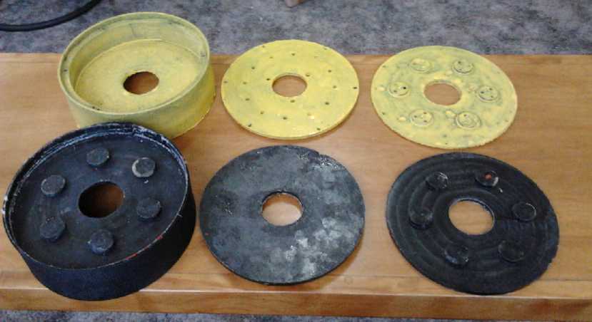
The body parts for two "Mini Electric Hubcap" motors,
one set drilled and painted with urethane, the other as cast.
On the 23rd I found a store on line that offered the
pressed bearings and I ordered 9 more, enough for 5 motors total. In
the last days of the month I slapped a few coats of polyurethane paint
on one set of body parts. On the 28th I got some 1/8" "starboard",
black HDPE, with which to form better centers to wrap the strapping
around.
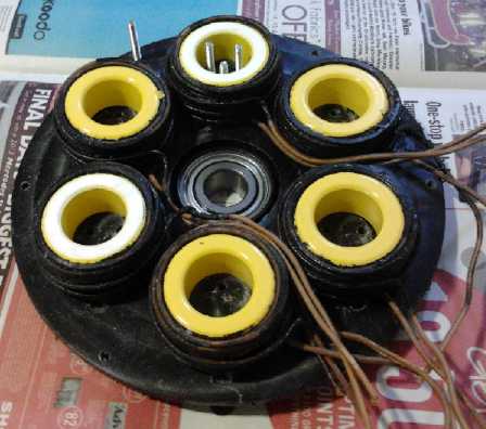
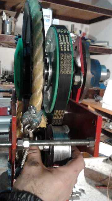
Fit of the coils
Checking the fits... all seems in order.
This is pretty much what it should look like when it's finished.
Cheaper Magnets?
I've been figuring for some time that the 1"x2"x.5"
supermagnets are probably thicker than what's really needed, and I
ordered some 1"x2"x.375" ones this time instead.
And in exploring the feasibility of using electric hubcap
motor coils to make a rim motor for bikes, where the coils only extend
in an arc on the upper side of the wheel but magnets go all the way
around the big bike wheel (18 for my bicycle - and that's leaving
every second space empty), the problem of cost of
supermagnets arose. They've come down substantially after their huge
jump in spring 2011, but are still by no means low cost. I found some
ceramic cup
magnets that seemed to have considerable strength on the active face,
and cost 1/2 as much as the smaller supermagnets:
Ceramic cup magnets are widely used in
industrial
applications such as fastening, holding, hanging or retrieving objects,
etc.
Ceramic Cup Magnets Size: 2.6"
Diameter x 0.37" thick with 0.23" hole
Magnet: Ceramic magnet ring
Cup Coating: Nickel
Magnetized through thickness, poles on the flat surface
Holding power: 50 lbs
Then I started considering whether this sort of magnet might also be
used inside regular Electric Hubcap type motors, and I ordered some
that could possibly replace them to try out. 8 slightly smaller ones
would just fit on the 7.5" "mini" Hubcap rotor and have good force.
Ceramic Cup Magnets Size: 2"
Diameter x 0.3" thick with 0.26" hole (OD 51.5 mm x ID 6.5mm x 7.7 mm)
Magnet: C8 Ceramic magnet ring
Cup Coating: Nickel
BrMax: 3850 gauss
Magnetized through thickness, poles on the flat surface
Holding power: 40 lbs
Note: holding power should be tested for your
specific application
I got 20 large for the bicycle wheel and 10 small for the
small
version Electric Hubcap. I was told they all come glued in with the
same polarity. I hoped I could unglue and
reverse 1/2 of them without breaking more than two of each. There was
also a 3" size and some smaller ones, but the sizes didn't seem as well
suited to 2" coil cores or the spaces available to put them.
When the magnets arrived, after finding the polarity on
most of the magnet was indeed the same (except that the smaller were
the reverse of the larger), I found out by a nasty surprise that four
of the larger magnets did have opposite polarity. Two that should have
repelled snapped together with enough force to give me a considerable
blood blister on a finger that was in the way. Don't believe everything
people tell you! I was being rather casual because they were "only"
ceramic magnets, not supermagnets.
The depth of field is certainly less than with the
supermagnets - the force decreases more rapidly with distance. This is
partly because they're weaker, and partly because they're also thinner.
The choice of sizes is quite limited. A smaller flux gap will help, but
the maximum torque of a motor using them will doubtless be lower. If
Victoria Waterjet doesn't have my steel rotors done soon the first
'mini' motor may have a lexan rotor with cup magnets.
Bike Arc Motors - a Start
On the 24th, I changed the ancient tire and tube on the
back wheel of my bicycle (making it actually fit to ride again
for the first time in some years) and layed out the 2.6" cup magnets to
check the fit. It appeared that if the magnets were placed at about
18-3/8" center diameter, every second magnet would just touch the spoke
ahead and the one behind. So I planned to mount them behind a lexan
ring of about 21.5" O.D. and 15.25" I.D, leaving a ~1/4" margin inside
and outside the magnets.
Spokes are a subject of special interest with hub motors -
often regular spokes wear out and break rather quickly, and thicker
spokes are desirable. The forces operate over the length of the spokes.
With this motor, the forces act out near the rim, which is what is
being driven. Obviously if they were at the rim or virtually there,
there should be no extra forces on the spokes. But pushing sideways in
the middle area just might be worst of all. How they'll hold out I
won't try to guess. The more even the forces the better, and I'll do
what I can to connect the lexan ring to each spoke on its side of the
wheel. If it's a serious problem, I might look for a way to attach it
to all the spokes, or more directly to the rim. For now, I may print
some special spoke-slot clips to screw the lexan securely onto the 18
spokes on its side.
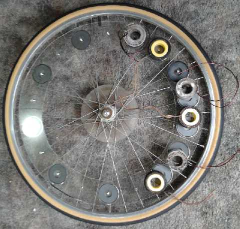
9 N and 9 S magnets didn't leave enough space for the coils, so they
had to be spread out.
Even with interleaving the two sets of 3 by reversal of polarity on one
set, it occupied more of the rim than I'd hoped.
Then I tried a different arrangement of 9 unipolar magnets, but the
coil spacing didn't change much.
It still stretched way back past the supporting frame, and I wasn't
keen on having a coil under a strut where it might not have room to
adjust properly.
I ended up with this arrangement of just 6 unipolar magnets, which
spacing resulted in the coil arrangement I wanted.
The question now is, will so few magnets so far apart have enough
magnetism to provide sufficient torque?
On the 21st, someone phoned about the Hubcap motors. He
hopes to convert a minivan with a blown engine, and has bigger plans
too.
Of course I had to say that while the motors and controllers are
operational, I still haven't created a successful variable transmission
and got a car going. Evidently he has considerable mechanical
experience and that didn't seem to phase him.
Planetary Gear Torque Converter (PGTC) Project
Toyota Prius Planetary Gear 'Torque
Converter'
Someone gave me this great
link to an interactive animation of how the Toyota Prius's "Power Split
Device", a sort of planetary gear torque converter that combines two
drive inputs with a third on the drive shaft. http://eahart.com/prius/psd/
Applying the animation to the PGTC is a little tricky. The
Electric Hubcap motor is in the position of "MG1" (sun gear), which
unfortunately
can't be moved directly. "ICE" is the amount of slip on the planets
assembly, governed by the slip-clutch-rope-pulley assembly. "MG2" is
the output drive shaft. Move "MG2" to -2 MPH (-130 RPM), and with no
slip (ICE=0), the motor (MG1) is doing 338 RPM. The slip ("ICE") can
only
be set either to 0 or above the top of the red line to 998 RPM (call it
1000). There, the motor ("MG1") is doing 3930 RPM to go that speed,
instead of 338. There's a reduction of almost 12 to 1 from the motor to
the output shaft.
This is actually a pretty high RPM for 2 MPH. The 130 RPM
of MG2 versus the car speed indicates that there's around a 4 or 5 to 1
gear reduction from MG2 to around 28 RPM on the wheels, depending on
the wheel diameter. So the total reduction is 338/28=12 to 1 with no
slip, or 3930/28=140 to 1 with 1000 RPM slip on the planets assembly.
Double the slip to 2000 and the motor will be at its maximum RPM
without hitting 2 MPH.
There's how it's supposed to work.
I also looked up some variable transmissions on youtube.
One called the "D" drive had a number of gears including planetary
gears, but I wasn't entirely convinced it did essentially more than my
PGTC, with a lot of extra complexity. On the other hand, my system
too appears to need a little more complexity to make it work as planned.
How not to test - Torque tested: yuk!
I (finally!) took the unit apart and restored the 4 to 1
chain drive for the time being. It took all of an hour. Then I thought
about putting the torque wrench on the converter output shaft. Then I
thought, "Why am I taking this thing out to the car and trying to move
the car at all, without knowing in advance how much torque it has? I
can simply C-clamp it to the bench and see what it puts out with the
torque wrench. If it doesn't have about 30 or more foot pounds to give
at least 120 at the wheels, there's little point installing it in the
car."
I guess when I started I had high hopes, and the obvious
thing was to connect the transmission to the gear shift lever to
tension the rope. Then I found I could tension it by hand at the unit,
but I just kept taking it out to the car and installing it to try out
each modification, repeating the pattern without thought.
So when I got the unit reassembled with the chain drive
(needlessly) reinstalled, I set it up on the bench. Even with all the
improvements, the PGTC didn't have 30 foot-pounds: it had 9 or 10
maximum. If I clamped the pulley for zero slip, the stalled motor gave
it about 22 foot-pounds, pulsed with what was probably 60 or 70 amps
for a second
or so. (With the planetary gear ratio being about 2.2 to 1, this
indicates about 10 foot pounds from the motor - somewhere around 1.4 to
1.7 foot-pounds per 10 amps. This is actually higher that the 1
foot-pound per 10 amps I had estimated. It shows the value of
definitive spec testing... that hasn't been attempted since early
prototype
motors and even then was never complete.)
What kind of a torque converter is putting out less torque
than the straight gear ratio? Do I have the whole theory all mixed up
in my head? Is this really better than the magnetic converter idea? At
least that one could conceivably be built up to quite high
torques
with enough magnets and copper.
Could it be a case of reduction "ratios" being somewhat
meaningless
when dividing by zero? - the whole operation doesn't work with the
wheels
stopped? Or from another viewpoint, power = torque * speed, and speed
was zero. Evidently lugging the motor more and more heavily with the
slip pulley
only reduced the motor speed.
I take some heart in the fact that on the occasion in
September when I got the car moving while standing at the hood, once it
started moving, it seemed to surge ahead unexpectedly strongly. At that
moment, I was sure I had it. In that case, how would I get the output
shaft turning before the car starts moving? This is starting to feel
like that old "catch 22" problem - you can get it moving if it's moving.
Final Drives: Flat Belt (99% efficiency)... and Clutch?
If the torque
converter doesn't work until everything is turning, perhaps what's
needed is a clutch? If the shaft has lots of torque once it's rotating,
it'll
definitely work - and even an idling speed gas
engine creating little torque will
start a car moving if the clutch is engaged slowly enough. It's
another sort of gearing down. If the clutch is popped quickly, even an
engine considerably revved up may stall.
So a second thought
was to put a clutch on the flat belt drive, using a loose drive belt
and
a roller that comes in from the side to put pressure on the belt to
gradually engage it. Of course it's a whole new complication to the
system and for the driver... but not ridiculously difficult or complex.
It might "do the trick".
(Another way to do the clutch could be to move one of the
two pulleys in and out to loosen or tighten the belt, with no 'idler'
pulley at all. This could be pretty easily arranged on my unit except
that the motor shaft wouldn't move with the output drive shaft, causing
misalignment in the planetary gear. Oh well!)
I did do a bit of experimenting with letting the belt slip
last month. But tho it tracked well if it didn't slip, it would run off
the side of the lower pulley if it did. It would seem the idler pulley
had best have side walls, and it might need another guide on the other
side, too. Come to think of it, it may need an idler wheel on
each side - for forward and reverse.
Another thing... if the PGTC output shaft has to be
turning to work, I can't use the torque wrench on it. I can only test
it by installing it in the car and seeing what happens... just like the
previous tests up to now. ...unless I can find things that fit in the
spline shaft sockets of the differential, lock one side, and connect
the other to the torque wrench.
I found this info about flat
belts. (I omit "irrelevant" sections. URL: http://machinedesign.com/BDE/mechanical/bdemech1/bdemech1_11.html
)
Flat belts
Recent developments
in flat-belt technology have overcome their previous drawbacks of high
tension and mistracking. New designs and advances in materials have
made both low and high-power transmission practical and cost efficient,
and at speeds that usually exceed other belt designs.
Higher power flat belts.
Developments here include sticky yet abrasion-resistant rubber
compounds that eliminate the need for high tension to grip pulleys.
These materials also allow lower shaft and bearing loads to transmit
significant power. The strongest flat belts now transmit over 100
hp/in. of belt width.
Different flat belt
surface patterns serve different transmission requirements. For
example, in high-power applications and outdoor installations,
longitudinal grooves in the belt surface reduce the air cushion that
flat belts generate when they run at speed onto a pulley. An air
cushion reduces friction between pulley and belt. In addition, the
longitudinal profile nearly eliminates the effect of dirt, dust, oil,
or grease. Furthermore, the grooves reduce the noise level of an
already quiet power transmission design even more.
Perhaps the most
significant advantage of flat belts is their high efficiency -- nearly
99%; about 2.5 to 3% better than V-belts. Three factors account for the
good efficiency: lower bending losses due to the thin cross section,
low creep because of special friction covers and high modulus of
elasticity traction layers, and no wedging into pulleys like V-belts.
Without the wedging action as in V-belts, flat-belt and pulley wear is
minimal.
Flat belts offer
greater design freedom than standardized designs because they are
available in most any width and length, in increments of 1/16 in. This
means drives can be sized closer to optimum rather than the next size
larger.
Pulley alignment is
equally important to flat belts as it is to other styles. Crowning at
least one pulley, usually the larger one, improves belt tracking. Flat
belts are forgiving of misalignment; however, proper alignment improves
belt life for any drive.
And by typing enough descriptive words, I finally started
to find places selling flat belts on the web, hidden between all the
hits on "Alibaba and the 40,000 fake hits" and many kindred search
results thieves. One place will make you any length and width of
urethane flat belt, in thickness from 1/16" to 1/8": http://ebelting.com/ . But the stretch
figures seemed high, several percent, and it turned out they were only
for low power use. So far, the one I got at the car parts place is the
best. What luck it was just the length I needed!
Besides it being the most efficient, and being amenable to
clutching, another reason for the 1 to 1
flat belt drive is that the motor RPMs through the planetary gear (with
no slip) will allow highway speeds. The 4 to 1
chain drive makes a useful test, but the motor would be revving too
high at too low a speed to be practical on the street. (My original
plan was to change the chain sprocket to get 3 to 1 or less once I had
something working, and then only drive it in town.)
Polypropylene or Nylon Strapping for Flat Belts?
After I wrapped polypropylene strapping around the rotor
compartment of the new Mini Electric Hubcap motor, I occurred to me
that PP strapping would make a fantastic flat belt. It's very strong
(like the yellow PP ropes), thin and so flexible it would go around the
smallest pulley virtually without frictional loss. The ends could be
melted, glued or sewn together to make a continuous belt. It comes in
long rolls in widths of .5", .75", 1", 1.5", 2", and 3" (and probably
more sizes). The narrower sizes are under a dollar a meter. My 1" x 38"
belt for the Chev Sprint would be around 1$.
If as seems likely the plastic proves too slippery, the
belt could be sprayed
or painted with urethane or some sort of rubbery substance having more
grip. Or the pulleys could be so coated. Or both.
In combination with printed plastic pulleys, here we have
potentially
not only the most efficient possible drive system, but the cheapest and
easiest to do belts for.
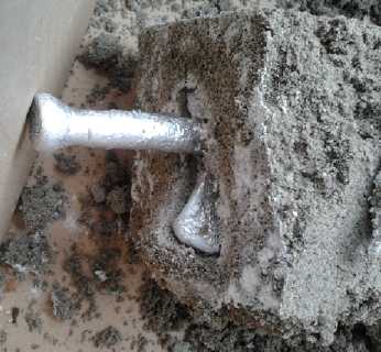
Clutch Mechanism
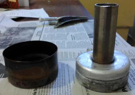
Salmon tin casting in two pours.
I had to cut off and then cut a slit in the remaining stainless pipe to
get it out. I won't do it that way again!
 On the 11th,
after deciding a clutch is probably what the
whole thing needs, I thought about the idler pulley. Could I find what
I wanted? Skeptical of that, I didn't try. Instead I cast an aluminum
pulley in a salmon tin (while I was casting an aluminum propeller
blade), and then machined it to shape on the lathe. (Much later,
someone pointed out that you can buy round aluminum stock in various
diameters.)
On the 11th,
after deciding a clutch is probably what the
whole thing needs, I thought about the idler pulley. Could I find what
I wanted? Skeptical of that, I didn't try. Instead I cast an aluminum
pulley in a salmon tin (while I was casting an aluminum propeller
blade), and then machined it to shape on the lathe. (Much later,
someone pointed out that you can buy round aluminum stock in various
diameters.)
The casting didn't go well. The aluminum didn't seem to
want to pour, and I didn't get the tin half full. So I did another
crucible of it and poured some more. It still didn't get it as full as
I wanted or expected. It's wide enough for the 20mm belt, but if I get
a
much fatter one, it's too thin. (It might manage 1" if I turn the
sidewalls really thin.) I thought the top pour would would stick to the
bottom half, but I had two
separate halves. Rather than do it over, I drilled holes and bolted
them together with flat head 1/4" bolts, recessed in for the machining.
Next time I'll use a stainless steel pot that holds more aluminum than
a small pumice pottery crucible.
It's the first aluminum thing
I've machined on a lathe, and I must say it's far easier to shape
than steel. With the thin and uneven casting, it has some defects -
pits and
voids - but it should suffice. I turned the center to fit two sealed
bearings I had in a drawer that I thought were for a 1/2" shaft, but
they turned out to be 14mm. Sigh - good luck finding metric bolts
around here! I did find some 15mm bearings with the same outer size,
which happens to fit a 5/8" bolt.
My Sprint had been an automatic. On the 12th I went out to
an auto wrecker and got a Sprint clutch pedal and cable. I
then considered that maybe the clutch could be activated by linking it
to the same lever as the PGTC slip pulley, since they did essentially
complementary things. Then I decided again to go for the pedal.
But by the end of the month I hadn't found any time to
start putting the pieces together.
Mushroom Outboard (Outboard Motor from Scratch) Project
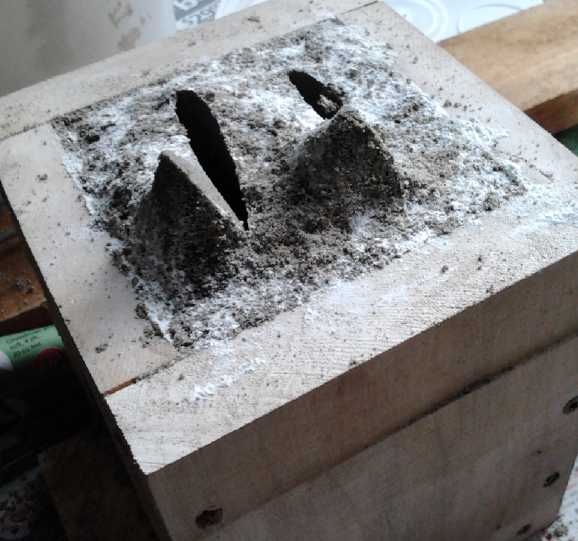
Bottom of prop sand (& clay) casting mold
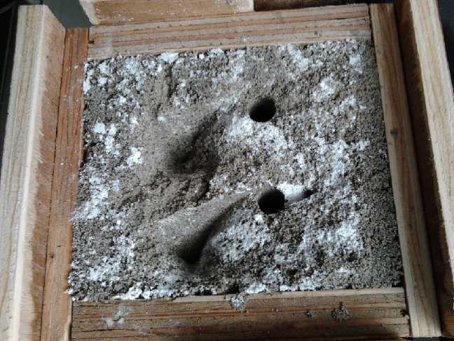
Top of mold
 The second propeller
casting, trying to do two blades at once, came close to disaster. I
guess I poured the
aluminum too fast, the sand was too wet, and the air vent was too
small. It got a steam bubble and blobs of molten aluminum erupted 2 or
3 feet into the air. By some small miracle, none of them hit me or
anything important. The burned pieces of wood on the sand casting form
are a reminder. The prop itself (nothing flowed into the second
chamber) was essentially hollow.
The second propeller
casting, trying to do two blades at once, came close to disaster. I
guess I poured the
aluminum too fast, the sand was too wet, and the air vent was too
small. It got a steam bubble and blobs of molten aluminum erupted 2 or
3 feet into the air. By some small miracle, none of them hit me or
anything important. The burned pieces of wood on the sand casting form
are a reminder. The prop itself (nothing flowed into the second
chamber) was essentially hollow.
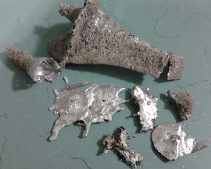
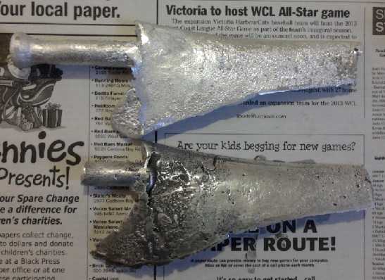
For the third casting on the 11th, I made a bigger air
vent to ensure it didn't get clogged, and I poured slowly and evenly.
This time, the result was mostly good, but the aluminum froze before
filling the thin trailing edge areas of the blade, so I must have
poured too slowly. And some lump of
sand must have fallen into the bottom because there was a large void at
the tip of the blade. (I also poured a pulley for the Sprint
transmission clutch in a salmon tin, and then switched to working on
that project.)
Breaking open the sand/bentonite clay mold.
First prop blade (lower - blackishness is polishing compound) &
third one.
Both 'close but no banana' so far.
Then I found on youtube
where someone did "lost PLA"
casting. He made the parts he wanted on his 3D printer, and used a
mixture of 50% sand and 50% plaster of paris (by weight or by volume
wasn't specified). He burned out the PLA plastic and then poured in
aluminum. The result was so good he didn't need to do any machining.
Instead of sand grain texture, the surface detail was so fine it showed
all the texture the 3D printer had put in the original plastic. Wow,
that's for me for the next try! I even have some plaster of paris.
When I have one good aluminum blade I'll probably use it
to form a
polyethylene mold to cast props in PP-epoxy. But for December, other
projects and Christmas intervened.
Turquoise Battery Project
A person who
contacted me about Hubcap motors was also interested in manufacturing
batteries. I told him about the Mn-Mn chemistry in moderately alkaline
solution. I also wrote a lengthy e-mail about battery construction to
the "Edison_NiFe_Batteries@yahoogroups.com" list in response to someone
who was trying to make a battery and had some fundamental flaws in his
design.
Few people seem to have have a good grasp of all the
essential principles of what makes a good battery, and then even those
who get it figured out need to find or create practical,
workable constructions and manufacturing techniques. And those who may
have all this don't seem to be sharing in a manner that might enlighten
most people. These hurdles have so far
stopped most everyone from making practical, marketable cells, ie
beyond experimental prototypes, and from expanding in new directions.
After starting with the common ignorance myself and having learned a
few necessary things about the subject over five years of time
consuming, hard won experience, I now hope to give others a head start.
When the printer was running again, I 3D printed a porous
electrode plate with the somewhat conductive ABS plastic. Regardless of
printer settings, I couldn't seem to make it porous. The problem with
all of them is that the first layer of plastic spreads out against the
glass and tends to join up with the bead next to it, and the carbon
fibers in the conductive type made it a little fuzzy, and the plastic
filled in everything even if printed quite thinly.
Coming back to the problem on the 23rd, I decided I should print
a first layer of vertical lines with spaces between them. The porous
front face would print on top of that. Then the 'pixels per mm' printer
setting should do a pretty good job of determining the porosity. The
exterior vertical line spaces would also be a passage for gas bubbles.
But when I went to do it I had a frustrating time. When it
was finally printing the bars, and then printing porous instead
of solid (by setting the print density from 980 down, down, down, down
to 300), the result was a globby piece instead of smooth and even, with
"pores" that were either filled in solid or gaping holes. Flexed
slightly, it started to break up. I thought I'd have to give up on the
conductive ABS, but further experiments the next day showed that a
setting of 430 gave decent results.
But again, the pores looked big enough to leak electrode
substance. Even as I worked, my thoughts drifted back to watercolor
paper or other microporous material being the right sort of consistency
for electrode separators. But if they were external to the pocket,
essentially one didn't have self contained electrodes any more. If they
were inserted inside, they'd surely be torn to mush as the electrode
substances were being compacted. That left putting the paper in its own
pocket between two porous plastic walls. In this case, the pores could
be very large, just fine enough to ensure the paper wouldn't rip during
construction. That would make the electrodes thicker and put more space
between them, increasing battery size and decreasing current capacity.
Even as I finally started getting conductive ABS
pocket plates that looked like they might be usable, I started thinking
again of abandoning the pocket electrode construction. But other types
have their own problems, and I hadn't been very successful with them so
far! In particular I have trouble making electrode briquettes that stay
together long enough to put them into a cell - that's the biggest
attraction of the pocket electrodes. Hmm... what about that stainless
steel form to feed in and compact stuff from the end with a press?
Note: Later I found that the carbon fibers of the conductive ABS had
clogged up the extruder head around the outside of the nozzle and the
teflon cone. That caused other filaments to stick to the head and ruin
each print, and it took disassembly and a considerable cleaning with
acetone, methylene chloride and several cotton 'Q-tips' to render it
useful again.
Filler/Airlock Caps
One thing needed for flooded cells regardless of inside
details is caps to fill the cell through, that will block air passage
once closed except to allow excess pressure to vent off. On the 27th
and 28th I designed and 3D printed a few attempts at making a two part
cap. I didn't however have little balls to put in them.
The base part of the bottom piece will insert and glue
into a hole in the top of the cell. A small ball is placed on this as a
sealing piece. The top piece is a friction fit over the bottom, and has
a small plastic spring to exert pressure on the ball to seal the cell
unless the pressure is too high.
I was thinking of some sort of twist lock, but the pieces
are a close fit, and they print slightly oval with forces on the
plastic. They "twist lock" together just fine without making anything
special for it.
I couldn't think of where or what I might use for sealing
balls. Ball bearings come immediately to mind, but I suspect they'd
quickly corrode and lose their seal. I'd think soft rubber ones would
be ideal, but where would they be found? More likely prospects would be
glass or plastic. I thought of some small size marbles I'd had when I
was a kid. Even those would have been larger than I wanted.
 The most
likely idea my brain could come up with was Michael's Crafts store, and
I swung by there en route to a Christmas social destination. They
indeed had small (~9mm) and cheap clear glass spheres, in bags of what
looked like a couple of hundred, for flower arranging. I'd found my
marbles! The surfaces weren't however flawless, with a few pits and
indented swirl patterns on the surface visible under a magnifying
glass. I decided they'd probably be good enough if the seat was well
done and matched the lower curve of the sphere. For that job, I'd
either heat the glass sphere and drop it into place to melt into the
seat a bit, find a router, drill or sanding wheel that would make the
right shape... or perhaps best, drop the glass sphere (or still better
a smooth ball bearing the same size) into place and drip some methylene
chloride on to soften and shape the plastic.
The most
likely idea my brain could come up with was Michael's Crafts store, and
I swung by there en route to a Christmas social destination. They
indeed had small (~9mm) and cheap clear glass spheres, in bags of what
looked like a couple of hundred, for flower arranging. I'd found my
marbles! The surfaces weren't however flawless, with a few pits and
indented swirl patterns on the surface visible under a magnifying
glass. I decided they'd probably be good enough if the seat was well
done and matched the lower curve of the sphere. For that job, I'd
either heat the glass sphere and drop it into place to melt into the
seat a bit, find a router, drill or sanding wheel that would make the
right shape... or perhaps best, drop the glass sphere (or still better
a smooth ball bearing the same size) into place and drip some methylene
chloride on to soften and shape the plastic.
The ball size was larger than my larger design. In fact
the larger diameter piece seemed just about right for use as the
smaller. So the size went up again, and got too large for the planned
thickness of the top of a cell. This could be accommodated with larger
pieces but with a smaller bottom stem that fit in a workable size hole.
Then I conceived that if I changed the cell top design a bit,
permitting an upright print orientation, I could print cell tops
complete with the lower filler cap as a single piece, allowing a bigger
hole and improving the 3D build accuracy, albeit adding a bit of
sanding or filing to flatten the faces that get glued.
After making caps to fit the glass balls, I had the thought that the
lower piece of the cap could be printed as a part of the cell cap
itself. So I made that, and tried to print a complete surround. But I
had trouble and (after cleaning the extruder) I finally printed a top
piece with integrated cap piece, and a cell surround complete with one
printed
face. I cut a piece of plastic for the other face, and I used a cap top
I'd already made. I put these together with the iron electrode that
worked, and a new one with conductive ABS and flexible graphite current
collector that had yet to be filled, to make a cell.
The components of a cell.
The flimsy flexible graphite gets pressed against the tab on the face
for connection.
The copper foil will be treated similarly in future.
The top edge will be modified with thinner stops at the terminal base
slots, to stop glue from running though into the cell.
1. glue the cap on and stack the internal pieces, then glue on the
second face.
2. glue on the second face, slip the components in from the top, then
glue the top on.
The second way is great for pocket electrodes. The first
way would be used to drop in current collectors, loose electrode
briquettes and separator components, then an expanding foam, forming a
stack.
After filling, heat glue is to be used to seal around the
terminal posts. (If it reacts, it may have to be wax or something.)
Electrolyte is added, and finally the ball covers the opening and the
cap covers and holds the ball.
The cell as it will appear before heat glue seals the terminal posts.
It's getting closer to what might be considered
reproducible, but now I think once I have working electrodes, even if
they're still pocket electrodes, they'll be glued directly to the cell
walls instead of being separate internal pieces, saving 3mm thickness
and some weight. So this 15mm thick unit is still a test cell and it
gets clips to hold the top of the walls together and modeling clay
instead of heat glue around the terminals.
But I'm thinking of a new, fast way to compact briquette
electrodes from one end, probably with a screw press such as the book
press. It's going to take many cells to do a solar installation, and
hundreds to do an
electric car, and any too-tedious steps to making them are going to
make them
impractical.
Finally on
January 2nd I decided I couldn't just leave it there almost
finished. I took a concoction of 25g KMnO4, 17.5 g graphite powder, a
gram of Ne2O3 and a gram of Sunlight dishsoap (that had been sitting
open on the counter for months), and added 10 g of nickel hydroxide and
a bit more dishsoap. Then a bit of water to make it into a dryish
paste, and I stuffed about 13 grams of it into the pocket plate with
the conductive ABS. I sealed the top with wax. I had a hard time
getting the sticky casting wax to stick. Finally I found the problem
was that the bristles of the paintbrush were pretty much dissolved or
melted off in the wax.
In the process of handling to fill and seal the electrode
some more of the terminal and another part broke off. Much more loss of
material would have been a problem, but everything still connected.
I then assembled the cell with a piece of watercolor paper
(hopefully) blocking the entire space between the two electrodes. The
top got some duct seal. It took about 40cc of electrolyte to fill the
cell with a 6 or 8 mm reservoir above the pocket plates. The color
turned purple from the permanganate.
The cell charged up but didn't seem to have a lot of
current drive. It could drive about 50mA without excessive voltage drop
(but preferred 25mA or less), and it put less than .4V/.4A into a 1Ω
load. Since the same Fe negode sourced over an amp in the Changhong
cell, the weakness is either the electrolyte or (much more likely) the
posode. For one thing, I should have added more graphite powder when I
added the nickel hydroxide. There seems to be a sort of "critical
concentration" of conductivity additive powders, around which the
resistance drops or rises rapidly with a relatively small increase or
dilution.
When the charge is removed, the cell begins a slow but
continuing discharge from 1.7X volts with no load, to 1.2X volts
overnight. (Theoretical voltage for the cell at pH 12 looks like about
1.55 volts from the pourbaix diagrams.) Either something touches,
there's something in the electrolyte causing discharge (perhaps an
impurity from the new electrode), or there's enough air leaking in the
top to do it. Some extra modeling clay around the top seemed to help...
or was it the additional charging since the last check?
A check the next morning revealed that the pH was low,
just 8. There might perhaps be some solubles forming and causing the
trouble. It seemed I hadn't added enough calcium hydroxide, or that it
had been consumed. In addition, the purple color had vanished and the
electrolyte was clear. The water level was also low, whether from
leaking or from internal consumption I don't know, and I had to add
some.
At any rate, the cell doesn't leak and liquid isn't
wicking up and out like with previous recent cases. The design seems
quite usable and is likely to be the final form except for dimensional
adjustments for electrode sizes and thicknesses. Except for the lid
with the tricky airlock/filler cap and the slots for the terminals, the
cell could be made equally easily from flat stock plastic or by 3D
printer. With a bit of crafting, the filler cap might be formed from
small ABS pipe or tubes with two telescoping sizes.
Soon I'll take the new electrode out, dry it out, put in
some toluene, and see how much dissolving the graphite and having it
resolidify as the toluene evaporates into random conductive forms of
nanotubes, lamilae and graphene, improves the conductivity. If it's
much better, great. If not, I'll add some graphite to the remaining mix
and make another electrode.
At the same time I can rinse both 'trodes and the case,
replace the electrolyte, and see if that stops the self discharging. If
it's still happening.
After an overnight charge, on the 4th I started a load
test. The cell had reached 2 volts, which was higher than it should
get, and was self discharging only very slowly from there. It didn't
need refilling and it maintained its low pH of 8 in spite of a bit of
added Ca(OH)2 on the 3rd. A 50Ω load brought it down to 1.6 volts in
about 5 minutes. It's likely that some of the initially dissolved
manganate migrated to the negative electrode, discharged to MnO2 and
continued on to metallic Mn, giving higher voltage but not much
substance of it for running a load. The effect wouldn't be noticed with
an Mn negative electrode, since it would just be a trivial addition of
more Mn.
By 2 hours it was below .75 volts, having delivered only
about 36mA hours. The iron electrode was better than that in the
Changhong cell, so once again the finger points at the plus side.
Hopefully it will improve with cycling or with toluene - I want to try
it with an Mn negode next.
My latest vision of a final cell is one that the componets
are stacked into place via the open side, with the top already glued
onto the other side and edges. First is a thin layer of heat glue on
the tabs. Then the graphite current collector is inserted with its
terminal tab through the lid slot, then the posode briquette, then a
piece of watercolor paper, are laid on top. Then a porous plastic
grille is pressed on, which is glued into place around the edges, or
sealed with wax. Solid edges of the grille prevent leaks around the
edges of the paper, avoiding the need for very careful fitting of the
paper or wrapping it around the electrode. This positive half is then
wetted with methyl benzene (toluene) to improve the conductivity of the
graphite. The grille is a special vertically oriented one to provide a
path for bubbles of gas to rise to the surface.
Assembly continues with another piece of art paper
(optional?), the negode briquette, and the negode current collector -
copper or zinc foil depending on the electrode substance. Then the
other side is glued on with methylene chloride and the cell is put in
the book press to clamp it together while that sets.
http://www.TurquoiseEnergy.com
Victoria BC