Turquoise Energy News
#6
Craig Carmichael August 4th
2008
I spent most of June working on the Electric
Hubcaptm car motor and controller, but it
was getting hot and it bounced around a lot. To my surprise making a
new "cooler" motor stator and and an improved mounting
system took most of July.
The new motor turns the car wheel, but the motor
controller needs some redesign to sync to the rotor position.
That's likely to occupy much of August.
Then I hope to give the new Ni-La (3.25v cells)
Turquoise batteriestm more attention. About
all I've done since May is acquire a couple of chemicals, added a new
"component", and done a couple of intermediate battery
chemie things. And I'm waiting for another chemical to arrive.
It occurs to me, having "wasted" June and
July, that if I just change a pulley the wave power unit's
generator will probably spin, and that summer is the best time to be
at the seashore. But I've dismounted the unit to use the trailer for
other things, and for now the car motor and batteries get
priority.
Much of my writing this month is about the motor,
with some fairly in depth (ie boring) details.
Topics Below:
Electric Hubcaptm Drive
Motor Changes - cooling & mounting mods
Revised Turquoise Motor Controller
Cross Section of the Turquoise Batterytm (as currently envisioned)
The Electric
HubcapTM Vehicle Drive Motor
I found these remarks, in harmony with what I've
been saying, on the web site of a company that makes "top end"
custom motors:
"New synchronous motor designs using
permanent magnets make it possible to have low speed and high torque
in one package, eliminating gearboxes and other mechanical
components.
"Eliminating the gearbox saves space
and installation costs, energy, and maintenance, and provides more
flexibility in production line and facility design."
Amen! Then, changing the common radial flux motor
layout to axial flux can provide these advantageous workings in just
three inches "length", thus the Electric Hubcap
design.
Motor Cooling
When I put the voltage up to 36 volts (also as much
as 36 amps - headed for two horsepower) and tested for a while, I
could smell hot polyester. It seemed evident that the motor was going
to overheat when used at full power - perhaps 60 to 72 volts - and so
I did some redesign. Not wanting the complication of a liquid cooling
system, I attacked the problem of better air cooling from every angle
and made a new motor stator.
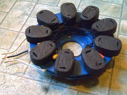
I discarded the solid cast stator. In its place are
individual cast epoxy coils that have no more cast plastic than
necessary to "pot" the copper coil with its iron strips and
two mounting bolts, into a solid mounting piece. Each coil, exposed to
the air on all sides, bolts individually onto the steel backing plate,
which is a disk brake rotor with heat dissipation vanes.
Washers on the mounting bolts hold the coils off the
backing plate's surface for all around air exposure, while the bolts
and washers carry heat and magnetism from the coil core into the
plate.
The front of a new fairing will have an air scoop so
the moving car blows air onto the motor.
An original cooling system feature remains: the
magnets on the rotor (the car wheel) act in principle as a centrifugal
fan to blow air across the coils, although the RPM is pretty low
except on the highway to move a lot of air. The magnets are mounted on
a solid steel disk bolted to the wheel, which may be expected to carry
off any heat buildup in the magnets.
Then, the coil wires have high temperature
insulation and the epoxy castings and flat black coating have very
high temperature ratings. The stator paint is engine enamel and the
rest is copper and steel, so the coils and stator can operate at
sizzling temperatures without damage.
Finally, depending on summer driving tests, if all
these "passive" cooling features seem insufficient or
marginal, an electric cooling fan - of whatever CFM rating seems
necessary - may be mounted. It would start if the motor temperature
gets too high, much like a radiator fan, to reinforce and provide
airflow even if the car is stopped. The fan's power would be
insignificant compared to the power of the large motor it cools.
It may be that a fan will be found necessary or
desirable but runs rarely -- at least in Victoria's mild
climate.
And again, having efficient motors with no gears
means less overall power and heat, and having two motors splits the
heat there is into two halves. Overall, prospects are excellent that
the motors will run a vehicle at trouble free temperatures in most
conditions. Fans should guarantee it.
An interesting feature of the new implementation is
the individual rather "generic" bolt-on coils. In theory,
they could be plugged into similar motors of various diameters and
ratings, from about 8 to 14 inches with perhaps 6, 9, 12 or 15 coils.
They can also be replaced individually if necessary.
July 19th: New Stator with better cooling
airflow completed.
Motor Mounting
After doing my best to stiffen the stator mounting
bracket, increasing the voltage still resulted in excessive vibration,
and finally I realized it would be very difficult to make a
sufficiently strong mounting for the stator in the available space,
with all the braces having to come around from behind the wheel.
The answer dawned on me on July 23rd: a thrust
plate with ball bearings to tie the rotor and stator together at
their centers. That way, the bracket from behind only needs to hold
the stator on and keep it from spinning. It doesn't need to be super
stiff. The thrust plate keeps everything aligned and sets the
stator-rotor air gap.
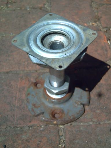
That evening and the next day, I puzzled with
various bits and pieces, piecing things together and seeing various
problems. Finally, some standard steel pipe end plates, a short pipe,
and a small "lazy Susan" ball bearing plate, brought it all
together.
A running test before supper showed this "platter" had
the desired effect. There was much less vibration, even though I only
had one of the two "arms" attached and it wasn't even bolted
solidly in place.
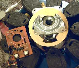
"Lazy Susan" thrust plate
assembly.
Standard pipe fittings have avoided the need
for custom machining.
The square end fits nicely between the four lug
bolts on the wheel.
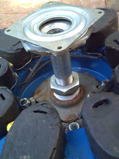
Thrust plate mounted. The length of the post
was just short, and a flat 5/16" plate placed on the end provides
3/16" gap between the stator coils and rotor magnets. A large air
gap increases efficiency and keeps the magnets from gradually being
demagnetized by coil flux and stator heat.
Another Voltage Possibility
Keeping to very low, and hence relatively safe
shock-wise, voltages, is less practical but not impractical. There are
nine coils in the motor, three per phase in series. If one wired them
separately, 24 volts would provide the same current per coil as 72
volts. They would also draw three times as much total current. (1/3
volts * 3x amps = same power.) One would replace each pair of 100+
volt, 100+ amp rated MOSFETs with three pairs of 50+ volt, 100+ amp
MOSFETs, one pair driving each of the nine coils. The total would be
18 MOSFETs instead of 6, and 9 heavy wires from the controller to the
motor instead of 3. To prevent the range from being cut by 2/3, one
would use 3 sets of 24 volt batteries, either connected in parallel or
perhaps one set per each three coils of phase A, B & C.
However, it would seem easier and more economical to
carefully make the 72 volt system as safe as possible. If the power
was such that it was difficult to drive with single solid state
devices, splitting the coils up with separate drivers might make good
sense.
Electric Hubcap Motor Factoids:
* Only the car's wheel turns. The only moving part in the motor
is a thrust plate centering the stator on the wheel.
* The virtually frictionless magnetic link to the wheel magnifies
useful power by transmitting it all directly to the wheel. There's no
losses from a transmission or gears, it requires no gear shifting or
other attention by the driver, and it's virtually silent.
* Permanent magnet synchronous motors also have the highest
intrinsic efficiency of all electric motor families, further
leveraging the efficient power transfer. As a guess, one might perhaps
expect up to 50% greater range than other electric motor systems from
the same energy, and correspondingly better performance for the same
kilowatts of electricity used by the motor.
* Installation requires no connections with or changes to the
car's existing mechanical components and systems.
* When not in use, the motor has no more effect on the car than
any other 35 pounds of luggage.
* The motor sticks out just 4" from the wheel or a couple of
inches past the fender, less protrusion than the outside rear view
mirror.
* The RPM with 13 inch wheels is about 10 per one kilometer per
hour of speed, that is, 450 RPM at 45 Km/Hour. Most electric motors
prefer much higher speeds, but the "Hubcap" has good low RPM
torque and power. 120 Km/hour is just 1200 RPM, a stately pace for
most electric motors but a good upper range for the
"Hubcap".
* The rotor is a 10 inch steel disk brake disk mounted on the
wheel lug bolts, 6 poles using 6, 12 or 18, .5" x 1" x 2"
NIB supermagnets, glued and-or bolted on.
* The stator is a similar 10 inch brake disk (but with cooling
vanes), with 9 epoxy cast coils bolted to it, each of 60 turns of #14
wire, in 3 phase "Y" configuration. Magnetic flux is
axial.
* A unique design breakthrough is that the stator coil iron is
strips of regular nail gun finishing nails in the coil cores instead
of custom die cut iron laminate sheets. With this and no axle or other
moving parts, the motor is simple enough to make at home, or the coils
could be wound by machine and cast, for super economical mass
production. Individual coils can be easily replaced.
* The motors dissipate their waste heat via air cooling, avoiding
the complexity of liquid cooling systems. There's maximal coil air
exposure and heat sinking with the magnets blowing air in front of
them, an air scoop on the front of the fairing and air guide vanes,
plus a temperature actuated electric fan in case all else is
insufficient at low motor RPMs that don't move much air and high power
(eg, climbing hills and mountains).
Turquoise Motor
Controller
I've been pleased that the solid state motor
controller with the high power MOSFETs actually drives the motor and
nothing blows up until I do something wrong. It's only been tested up
to 36 volts so far, but this testing has shown that lower voltages
should be used - perhaps 60 to 72 volts instead of 120 - so 36 volts
is actually at least half way (and 1/4+ of full power). Though heavier
wires are required for the same power, this allows choosing 100 volt,
120 amp MOSFET transistors, more economical than the 200 volt, 65 amp
parts. Bonus: the lower voltage is less likely to electrocute anyone,
though anything over about 40-50(?) volts or so must still be treated
as potentially dangerous.
However, I've finally realized that the "lumpy"
torque that leads to some of the vibration, and the "fragility"
of operation - a tendency to suddenly stall when the load gets a bit
too much - mean that the drive signals can't simply assume the motor
will synchronize to them: the driving power has to synchronze to the
actual magnet positions, somewhat like a DC motor with a
commutator.
Now that I'm addressing the issue, I see this can
actually simplify the controller circuit as the phases can be
generated simply by the optical shaft position sensors. But a slotted
disk, optical elements and additional wiring for them have to be added
to the motor itself, and the controller will of course need mods, so
the changes are likely to take up a good part of August.
Say, a cardboard cutout slotted disk should be
much easier to check for fit than a real metal one!
Will it slip on without disassembling the
thrust plate assembly?
Best to cut it so it will!
To the left: a convenient old mouse PCB with
four pairs of LED + phototransistor. This needs just three sets, one
per phase.
With the revised controller, which will have PWM
like most controllers, the gas pedal "must" (simplest) go
back from being a "speed select" pedal to a regular
"accelerator" pedal. In my view this is largely a negative
thing, but it's how we drive now anyway. And it does open the way for
a front wheel drive car to become an all wheel drive with electric
rear and gas/mechanical front drives, both on at the same time.
Speaking of which, a differential can let one wheel spin,
eg in mud or on ice, while the other is stopped and providing no
thrust. Both hubcap motors provide torque at all times: it's a better
two wheel drive.
Motor Controller Factoids:
The controller converts the DC power from the
battery to a variable frequency approximation of three phase AC power,
on three power wires that go to the motor to create a variable speed
rotating magnetic field in the stator, the motionless part of the
motor. That field pulls the permanent magnet rotor on the wheel around
with it and hence rotates the wheel.
Optical sensors tell the controller the
position of the magnets to time the pulses. The amount of torque is
controlled by pulse width modulation proportional to depression of the
accelerator pedal. Torque to slow the motor is provided by differently
timed pulses proportional to the depression of the brake pedal. A
reverse switch switches the signals to reverse the rotation of the
magnetic field.
In accelerating, the motor uses energy from the
battery. In decelerating, the motor generates energy, which goes back
into the batteries.
Turquoise
BatteryTM
Here's details of the Ni-La bipolar flat plate
battery cell as currently envisioned. There are some uncertainties
that may necessitate a change or two.
First, the cell in cross section:
1. Nickel-brass plate cell wall (AKA nickel-silver but actually
has no silver so the name is misleading). The current flows through
the thickness of this plate across its entire length and width
straight into the next cell, so it's good for zillions of amps. The
two ends of the battery are extra thick pieces with bolt terminals
silver soldered to them, which should handle, say, many hundreds to a
couple of thousand amps.
2. A conductive layer of zinc mixed with the positive electrode
powder. This zinc is not added but leached from the surface of the
nickel brass cell wall sheet by electrophoresis.
3. The positive electrode powder/paste. This is the familiar
nickel beta [oxy]hydroxide, with a bit of cobalt trioxide added
(becomes cobalt hydroxide on first charging) to improve conductivity.
Pretty much the same as in Ni-Fe, Ni-Cd, Ni-MH...
4. The electrode separator sheet.
5. Ferric oxide (or osmium) powder layer. Smeared onto the
separator sheet, this acts as a hydride to store protons, hydrogen
ions. Os should have better performance, but though only a bit is
needed, Os is very expensive. Note that that gives us the basics of a
Ni-MH battery cell. The difference is that this is just a thin mid
layer. It won't hold many protons, but they just pass through to the
negative half of the battery.
This layer is important because it splits the cell
voltage into two parts: the positive side (1.38 volts per Ni-MH usual)
and the negative side (-.83v MH - 2.90v La/La(OH)3 = 2.07v). Water
based electrolyte starts to break down above around two volts, which
is why lead-acid batteries (2.1v) are the highest voltage cells
besides lithiums, which use a non-water-based (but very slow)
electrolyte. So splitting or "ramping" the voltage permits
creating the Ni-La cell, of 3.45v theoretical voltage.
6. Zirconium silicate (zircon) or zirconium oxide (zirconia)
layer. This is an electrical insulator that freely passes ions. It
insulates the ferric oxide layer from the negative electrode powder
while letting the protons and hydroxide ions freely pass.
7. Another electrode separator sheet. I'm not sure I trust the
zirconium to have 100% coverage!
8. The negative electrode powder/paste. About 6mm thick. This is
a 3 to 1 mix of monel and lanthanum [hydroxide], with a little cobalt
chloride thrown in for better conductivity. These ingredients are
mixed in a bean paste to add thiamine mononitrate, rolled out thin,
dried, and fried until the bean paste catches fire and burns off.
(about 90 seconds. This is definitely an outdoor job - the smoke is
awful! I turned an electric barbecue into a special oven.) The
"sintered" amalgamated powder is scraped off the sheets into
containers for later use.
9. An aluminum grid next to the cell wall to improve
conductivity.
10. The cell wall of the next cell. There's only one wall between
cells.
There are also the ingredients that aren't bound by
the layers. The first of these is Lemon Fresh Sunlight dishsoap
(accept no substitutes), which is mixed with the electrode powders and
turn into semi solid pastes. The second is the electrolyte, which is
poured in as water with potassium chloride (sodium free table salt), a
"tincture" of methyl-ethyl-ketone (nasty solvent), and
acetyl ester (AKA ethyl acetate).
The chlorine ions and odd organic ingredients in the
electrolyte [should] allow the reversible La <===> La(OH)3
electrochemical reaction for charging and discharging the negative
side of the battery. I did see almost three volts in one test, but
that was without the rust or zircon layers and the water discharged it
quite quickly. (That continuous discharge, increasing rapidly with
voltage, is perhaps why it didn't get up to 3.45 V.)
I'm hoping for many hundreds of amps capacity, even
1000+, in a battery whose maximum actual drain/charge will be under
200 amps with two hubcap motors at full power. (Pushing things to
extremes, just think: a 50 amp-hour battery could be charged in just 3
minutes at 1000 amps, a 72 volt battery drawing around 300 amps at 240
VAC. How big is the main breaker on your house?)
Now I've told you all the secrets... so what do you need me for?
Well, maybe you should hold off until I've actually got one
working.
http://www.turquoiseenergy.com
Victoria BC