Turquoise Energy News
#7
Craig Carmichael September 3rd
2008
But the "lazy susan" ball bearing unit
wore out amazingly fast, and 60 volts didn't roll the car. Rats! The
coils hardly got warm, so 120 volts would be fine.
I'm becoming chary of such battery voltages, so I've
rewired the motor coil connections from series to parallel to use
around 40 volts in place of 120, at what looks like it might be a
couple of hundred amps max current. The motor controller will need
beefing up.
Hopefully I'll be able to give the new Ni-La
(3.25v cells) Turquoise batteriestm some
attention in September, having done but little on them since May. I
don't think a lot more is needed to get them going. (But then the
motor has seemed tanalizingly close since June, so you never know for
sure.) Just twelve cells would give the 40 volts, and they should -
theoretically - be good for the very high amperages that are going to
be needed.
The question of whether we want battery and-or motor
manufacturing here in the west, or just to give away the new
IP/technology and then import everything from China, is now looking
for decision - a Chinese battery maker is already potentially
interested.
In the obviously coming switch to plug-in cars, I
should think making things here would improve our balance of trade,
and getting into the market early would place Canada as a market and
technology leader in the field. It should be a fairly easy thing to
do, but in my experience it's paddling upstream to move anyone around
here who has power to make things happen, so dealing with the Chinese,
who want to play ball, might well be the best - or only - way to get
them into mass production.
Topics Below:
Electric Hubcaptm Car Motor:
a recap
Rerevised Motor Controller - the
"Opto-electronic commutator"
Submarine Motors Project?
Who Killed the Nickel-Metal Hydride Battery? - and a
battery comparison
Previous Issues TOC
The Electric
HubcapTM Vehicle Drive Motor
Recap
Apparently I've not explained the whole purpose of
the Electric Hubcap in recent issues for newer readers, so I'll recap:
it's an electric motor add-on system to change gas (or diesel,
propane...) vehicles into highly efficient plug-in electric hybrids
that normally run on home electricity, turning on the gas engine and
putting it in gear only on longer trips when the batteries have run
down.
For all its absurdly small size and light weight,
this powerful electric motor has the torque to turn the car wheels
directly, with no gears or transmission. Someday not so far off, all
vehicles will be propelled this way.
It has important advantages over any other electric
drive system.
First, the old ICE drive system and mechanics is
unaffected. The vehicle can run on either electricity or gasoline to
fulfill all driving needs, with much less pollution, fossil fuel
usage, and cost.
Second, because it is the most efficient type of
electric motor and because it turns the wheels magnetically with no
gears or transmission, it uses perhaps 50% less energy. It will also
have regenerative braking, which has been estimated to further extend
range 20-30% in city driving. Thus, the electricity goes farther,
minimizing the battery power required and the impact on the electrical
grid should people switch en masse.
The frugally used batteries need only power a
typical day's driving, eg 30-50 Km, beyond which the "regular"
gas engine is used. (Three deep cycle lead-acid batteries might total
perhaps the weight of an extra passenger, not half a ton. and will
repay their cost with only about six avoided gas fillups!) If the
Ni-La Turquoise Batteries complete as expected, even the weight and
long-term cost of lead-acid batteries will be cut by four-fifths. The
"regular" car battery under the hood will be about the size
of a couple of coffee mugs.
I plan to put in optional "battery charge while
driving" on gasoline, so on an extended highway trip one can
alternate between periods of gasoline and electric driving, which I
hope will reduce overall gasoline consumption somewhat even beyond
plug-in range.
Wiring changes: The Electric Hubcap system needs to
be enabled by the ignition key on "Acc" or "Run"
to prevent theft and accidental vehicle movement, and either the turn
signals must operate with the ignition key on "Acc", or an
additional switch needs to shut the gas engine system off even with
the key on "Run". These changes will not affect normal
gasoline operation.
For city dwellers who rarely do extended highway
travel, a gasoline additive to prevent the gasoline in the tank, fuel
line and carburetor or injection system from going "stale"
after six or more months may be advisable.
And now back to our regularly scheduled progress
report.
August Motor Works
I managed to clarify (never hurts) the new motor
control design over the first week or more, and then picked away at
making it bit by bit, and finally "went at it" to try out
the new system, ignoring most other things, about the 14th to 17th. It
worked great! By the 26th I had wired up a single box housing all the
parts for the back end of the car: a main breaker switch, spike filter
capacitors, motor controller, plug socket for the motor, and all the
connections between them, and I mounted it in the back of the car and
tested on the 28th.
But I found the car didn't roll even with 60 volts
of batteries, and going to 72 volts surely won't make the difference.
(Two motors *might* have, but I still expect one to move the car.)
Evidently my original estimates of using 120 volts were more
realistic, and I was misled by the stopped motor currents being higher
than I expected: the currents drop rapidly with RPM to the ranges I'd
originally anticipated. However, I've reconfigured the motor to use
around 40 volts (to be determined) at triple the current. It's much
harder to electrocute yourself with 36, 40 or 48 volts, and the
minimum number of batteries for operation is lower. The heavy wires
are very short, with cables less than two meters in all. Things seem
to be headed straight to the specs ranges of the commercial car motor
controllers: low voltages and hundreds of amps of current
capacity.
"It's amazing what a few
hundred more amps can do!"
- J B Straubel, chief
technology officer, Tesla Motors
Finer Point
It appears electrical braking terminology is more
finely defined than I realized:
Dynamic Braking: Braking by generating
electricity, but generally applying the electricity across resistors
to make heat that usually goes to waste.
Regenerative Braking: Braking by generating
electricity that becomes available again, by recharging the car
batteries, or by feeding it back into a power grid (eg trolley busses,
electric railways).
I was using the two terms interchangeably.
Motor Cooling
The new "open air" motor design (made in July) seems to
cool well. The coils haven't been more than a little warm in tests so
far. This bodes well for running it at substantially higher powers.
Temperatures will be monitored with a sensor on the motor over more
extensive operational trials.
Motor Mounting & Tests
The "Lazy Susan" thrust plate (July) did
the trick for stabilizing the stator mounting, but it didn't last
long. It was quite "fried" after only 15 or 20 minutes of
1000+ RPM motor testing. I made a better one from a car wheel hub and
bearing. Since the optics used a slotted disk mounted on the lazy
susan, I had to change all that too, grinding slots in the hub and
remounting the LEDs and phototransistors. I just finished making it
today.
Then I tried out the motor, again with the car wheel jacked
up. It ran great on 12 and 24 volts. The currents were lower than I
expected, but a 40 amp phase drive fuse blew at 24 volts, indicating
over 60 amps from the batteries. Starting gently prevented a
recurrance.
Electric Hubcap Motor Factoids:
* One small but powerful hubcap motor supplied with 40(?)
volts has the power to drive a motor vehicle to highway speeds instead
of using the gasoline or diesel engine.
* Most installations are expected to use two for
left-right wheel balance and better, balanced, regenerative
braking.
* Only the car's wheel turns. The only moving part in the
motor is a thrust plate helping to keep the stator centered on the
wheel.
* The virtually frictionless magnetic link to the wheel
magnifies useful power by transmitting it all directly to the wheel.
There's no losses from a transmission or gears, it requires no gear
shifting or other attention by the driver, and it's virtually
silent.
* Permanent magnet synchronous motors also have the
highest intrinsic efficiency of all electric motor families, further
leveraging the efficient power transfer. As a guess, one might perhaps
expect up to 50% greater range than other electric motor systems from
the same energy, and correspondingly better performance for the same
kilowatts of electricity used by the motor.
* Installation requires no connections with or changes to
the car's existing mechanical components and systems.
* When not in use, the motor has no more effect on the car
than any other 35 pounds of luggage.
* The motor sticks out just 4" from the wheel or a
couple of inches past the fender, less protrusion than the outside
rear view mirror.
* The RPM with 13 inch wheels is about 10 per one
kilometer per hour of speed, that is, 450 RPM at 45 Km/Hour. Most
electric motors prefer much higher speeds, but the "Hubcap"
has good low RPM torque and power. 120 Km/hour is just 1200 RPM, a
stately pace for most electric motors but a good upper range for the
"Hubcap".
* The rotor is a 10 inch steel disk brake disk mounted on
the wheel lug bolts, 6 poles using 6, 12 or 18, .5" x 1" x
2" NIB supermagnets, glued and-or bolted on.
* The stator is a similar 10 inch brake disk (but with
cooling vanes), with 9 epoxy cast coils bolted to it, each of 60 turns
of #14 wire, in 3 phase "Y" configuration. Magnetic flux is
axial.
* A unique design breakthrough is that the stator coil
iron is strips of regular nail gun finishing nails in the coil cores
instead of custom die cut iron laminate sheets. With this and no axle
or other moving parts, the motor is simple enough to make at home, or
the coils could be wound by machine and cast, for super economical
mass production. Individual coils can be easily replaced.
* The motors dissipate their waste heat via air cooling,
avoiding the complexity of liquid cooling systems. There's maximal
coil air exposure and heat sinking with the magnets blowing air in
front of them, an air scoop on the front of the fairing and air guide
vanes, plus a temperature actuated electric fan in case all else is
insufficient at low motor RPMs that don't move much air and high power
(eg, climbing hills and mountains).
Turquoise Motor
Controller
The first test of the new design (details below) was
on the bench on August 13th. This was evolved from the occasional
hours of study and R & D I could squeeze in here and there:
figuring out the timing and the design, remaking part of the motor
controller, assembly and testing of the optical system, and some
resistor ohms changes based on those tests.
In defiance of Murphy's law, it spun up great on the
first try! With 12 volts, despite a one inch air gap, in less than one
turn in 1/2 a second it would get moving so fast that the heavy but
unaffixed rotor slid askew by centrifugal force.
For the first time, there was the sense of the POW
of HorsePOWer! What could it not do with a 1/4" gap, a doubled up
magnets rotor, and 60 volts!?! That would have to be settled with the
motor properly mounted on the car and with a proper pulse width
modulator driving it, not jury rigged on a table with a simple on-off
switch.
After making and testing a PW modulator the next
day, August 14th, I put it on the car on the 15th, and it ran well but
needed adjustments. On the 17th I tried again. Timing is everything:
With the photo couplers at the right angle, the RPM rises and the
current drops. At 24 volts, the current dropped from about 25 amps
with the wheel stopped, or 20 amps labouring along with poor optics
alignment, to under 10 amps (240 watts, 1/3 HP) spinning away. I
finally ran it up to several hundred RPM with 36 volts supply, but
chickened out of going to 48 volts.
After some time away, on the 26th I completed an
8"x8"x4" "main box" containing a main breaker
switch (100 amps), physically large motor filter ("run")
capacitors, a "dryer" socket to plug the motor drive wires
into, the complete motor controller unit (relocated from its original
separate box), and all the heavy wires connecting everything up.
I removed some gate diodes recommended by
International Rectifier from the controller, that I was sure in this
design were just going to cause trouble in the form of exacerbated
switching voltage spikes. Any spike that exceeds maximum voltage
ratings will probably fry the motor controller, and I'm getting tired
of fixing it.
So I felt more confident about going up to 48 volts
and beyond, and I installed the box and tried operation at 48, then
60, volts on the 27th. The voltage spikes seemed acceptable. The
jacked up wheel spun up to over 1000 RPM, but on the ground again the
car, though it shifted a bit, wouldn't roll on the gravel. Doubling
the voltage again to 120 volts (to provide four times the power)
looked like it might tip the scale. A second motor would ensure
it.
But I've decided against high battery voltages for
electrical safety reasons and have reconnected the coils for 36-40
volts in place of 120, with maximum current of up of to perhaps as
much as 300 amps instead of 120 amps.
The "Opto-Electronic Commutator"
In typical "dumb" AC power installations
(as best I understand it), synchronous motors have to be nursed up to
speed, eg with another motor. They run synchronously with the AC power
frequency, but if the load is too great, they suddenly stall and stop.
I experienced this in the tests with the electric hupcap. It didn't
seem like a very good way to run a car!
Synchronizing the drive signals to the actual
positions of the magnets instead of assuming the magnets will follow
the drive signals, changes everything. The motor is "synchronous"
only with itself. Power and hence speed is easily regulated by pulse
width modulation (PWM), essentially rapidly turning the power on and
off. For more power, it's on more (wider pulse width), and for less,
it's off more of the time, with the ends of the range at always on or
off. A pulse width modulator to work with the driver chips can be made
with a few cheap components, including a potentiometer under the gas
pedal.
One could synchronize a drive signal to the shaft
position with a traditional commutator. In this case, the simplest
design could be three rings and five brushes, subject to wear and
arcing on a rotor that doesn't itself use electricity at all, but
making it operate like a "dumb" DC motor.
However, to provide this with pulse width
modulation, reversing, and regenerative braking still requires a solid
state power controller that would still need four power MOSFET
transistors - and heavier ones - in place of the six that are used in
the brushless solid state control.
Enter optical sensors and a slotted ring. With three
LED/phototransistor pairs spaced apart by the angle between coils, and
a simple on-off slotted disk turning with the rotor and running
between the LEDs and the phototransistors, the signal timing is
generated by the magnet positions. The new thrust plate fortuitously
provided a ready means of mounting the rotating disk and these optical
magnet position sensors.
To turn them into drive signals they're simply fed
into the IR2130 MOS gate driver which which turns the appropriate
outputs off and on, feeding the high power MOSFETs which drive the
actual motor coils.
This makes the motor controller, together with the
optical components in the motor, essentially into a subcomponent of
the motor, an "opto-electronic commutator" that can easily
be made to also handle PWM, forward-reverse, and regenerative braking.
Now it works very specifically with the Electric Hubcap motor that has
the matching optical sensors, and the motor will work with this
controller only. Perhaps it's as well I made my own controller instead
of buying one!
The controller is changed, having now three control inputs from
the front of the car: PWM for the amount of power, forward/reverse,
and brake (derived from the brake lights). For driving we recognize
four conditions: go ahead, stop, go back, stop going back. The motor
knows only two: accelerate clockwise and accelerate counterclockwise.
Regenerative braking is just trying to go the other way from the way
it's going. However, the "brake" signal feeds the controller
logic to keep the car from zooming off backwards after you brake to a
stop.
Now I need to make the driver's dash control box with two PWM's
(for gas & brake pedals), change the car's signal lights to work
on "Acc", tie in the brake lights... and actually make the
Brake handler inside the motor controller.
As an intermediate step to get things going... just
one PWM on the gas, and no dynamic braking.
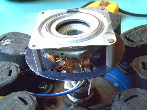
The "photo" end of the
"commutator". Optical sensor pairs
(LED<-->Phototransistor) protruding from thrust plate shaft.
These are alternately clear and blocked by the slotted disk that turns
with the thrust plate, magnet rotor and wheel - a most convenient
second function for the thrust plate!
After the testing, the lazy susan was worn right
out. So just a week after trying it out, I've had to make a new
"version 2" thrust plate with a car wheel hub and bearing.
Naturally, the optics mounting and board also had to be redone to
match.
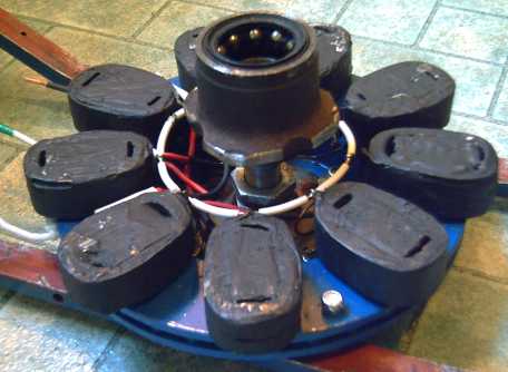
"Version 2" thrust plate with hacked
car wheel hub and bearings (optics weren't
mounted yet in this picture), in motor rewired in parallel for 1/3
voltage, aiming at 40v batteries (at 300 amps) instead of 120v (at 100
amps).
August 30th: Speaking of turfing cherished designs, it appears a
microcontroller might be a better choice than "simple"
standard logic chips after all. My latest design with regenerative
braking isn't bad, but a controller could reduce the 5 logic chips to
1, and 14 passive components to 5, at the small cost of adding a five
volt power supply. (The original logic ran at 12v battery voltage.)
That's quite a bit less PC board design and less soldering. It would
also provide more options such as operator displays for temperatures,
battery voltages, and so on.
Motor Controller Factoids:
The controller converts the DC power from the
battery to a variable frequency approximation of three phase AC power,
on three power wires that go to the motor to create a variable speed
rotating magnetic field in the stator, the motionless part of the
motor. That field pulls the permanent magnet rotor on the wheel around
with it and hence rotates the wheel.
Optical sensors tell the controller the
position of the magnets to time the drive pulses. The amount of torque
is controlled by pulse width modulation proportional to depression of
the accelerator pedal. Torque to slow the motor is provided by
differently timed pulses proportional to the depression of the brake
pedal. A reverse switch switches the signals to reverse the rotation
of the magnetic field.
In accelerating, the motor uses energy from the
battery. In decelerating, the motor generates energy, which goes back
into the batteries.
Submarine
Motors?
Funny, last month I quoted a blurb from a custom
motor manufacturer extolling the virtues of the permanent magnet
synchronous motor (PMSM), and one of their applications was large
submarine motors.
Now there's a possibility on the horizon of doing
two "electric hubcap" motors for a small, fast submarine,
driving counter-rotating propellers on concentric shafts.
In small subs, counter-rotating props are probably
the best way to keep the entire vessel from spinning around opposite
to the propeller rotation, but to have them both on one axis without
gears means the aft motor has to have a hole right down the middle for
the other shaft. As it happens, the hubcap can do that easily, and the
low RPM PMSM is especially suitable for subs. And it happens that two
"Hubcap" motors can also match the designer's target motor
input power.
Shafts, bearings and seals will be new engineering
considerations, but on the whole it looks quite doable.
The sub has appeal as an early custom project. It
does of course depend on the designer actually going ahead with the
submarine project.
Who
Killed
the Nickel-Metal Hydride
Battery?
Here's a quote from Wikipedia quoting from a book. Cutting
straight to the chase:
"It's
possible that Cobasys (Chevron) is squelching all access to large NiMH
batteries through its control of patent licenses in order to remove a
competitor to gasoline. Or it's possible that Cobasys simply wants the
market for itself and is waiting for a major automaker to start
producing plug-in hybrids or electric vehicles.*"
This is one of the main reasons I decided to try to
make batteries: Chevron et al seem to me to be abusing the whole
purpose of patents, buying it specifically to block access to the
technology, while manipulating the marketplace by buying up Cobasys,
the company that was all set up and raring to go to provide us en
masse with great Ni-MH car batteries. Instead of simply shutting down
the company, which could encourage a new company to start up, it would
appear they have cleverly limited access to Ni-MH batteries larger
than "D" cells and raised prices far above economic levels,
to delay as long as possible the advent of electric cars, and then
having done the world this service, to be ready to take as much
financial advantage of the batteries as possible.
"Ni-MH technology is good, but it's so expensive!"
they say. It would appear they've deliberately made it so, and that
they've managed thereby to steer everybody away from Ni-MH, by far the
most effective proven car battery technology so far, even though there
are other hydrides they don't have a patent for, including at least
one better one. Anyone else who now wants to start a new Ni-MH plant
must recon with the likelihood that Cobasys/Chevron/Texaco will
suddenly drop their prices to bankrupt them just when they're most
heavily committed for expansion. (and then raise the price
again)
I was originally going to make Ni-MH batteries on a
small scale, and I hoped to find a way to make them easily enough to
publish instructions on the web for any handy people to make them at
home.
Then I happened across the lanthanum-lanthanum
hydroxide reaction. A new and better chemistry, Ni-La, could change
the whole picture. (If it can be made at home, so much the better, but
it's looking like there are enough tricky things to do that not so
many people would care to tackle it.)
The well known nickel [oxy]hydroxide positive
electrode [+0.55 volts] that needs hydroxide ions to charge, may be
used with various negative electrode chemistries that all give off
hydroxide ions as the battery is charged:
(discharged) <===> (charged)
Iron: Fe(OH)2 + 2e-
<===> Fe + 2(OH)- [~ -0.8 v]
Cadmium: Cd(OH)2 + 2e- <===> Cd +
2(OH)- [~ -0.8 v]
Hydride: Metal + H2O + e- <===> MH + OH-
[ -0.83 v]
Lanthanum: La(OH)3 + 3e- <===> La + 3(OH)- [
-2.90 v]
The biggest practical difference between these
chemistries is the higher voltage with lanthanum. There are a few
other higher voltage elements. A factor in this type of chemistry is
that the material can only be recharged if its hydroxide conducts
electricity. Thus, aluminum [-2.3v] can be used in non-rechargable
batteries, but the Al(OH)3 is evidently an insulator, and so the
process can't be electrically reversed.
Another difference is construction. The big
nickel-iron cells are traditionally made quite differently to the
cadmium and metal hydride "AA" cells. Ni-Fe might be smaller
and lighter if packaged similarly to Ni-MH or Ni-Cd.
On the other hand, the bigger Ni-Fe cells with more
electrolyte are renowned for their robustness and decades of
longevity. Similarly, the big Cobasys Ni-MH batteries used in the GM
EV-1 looked like they might well outlast the cars. But the EV-1's
weren't on the road long enough for a definitive test.
But the lanthanum is where the real energy density
is! It just needs some extra tricks to make it work.
*Plug-in Hybrids: The Cars that Will
Recharge America, published in February 2007, Sherry
Boschert
http://www.turquoiseenergy.com
Victoria BC