Turquoise Energy
News #8
Craig
Carmichael
October 6th 2008
Contents:
The Month in
Brief
** Classes/Workshops: Battery
&
Electric Hubcap Motor Making
Electric
Hubcap Project Detailed
Report
rewiring; tests; new motor controller;
tests
Turquoise
Battery Project
Detailed Report
a bit of progress; Lead-acid: 1/4 cost
of gasoline
The Month in
Brief
Inventing and developing things would be so much
easier if you knew all about them from the beginning! Several
assumptions I made when I started proved, one at a time, to not apply
to PMSM motors, and I decided to strike out for a better battery
chemistry instead of simply copying known Ni-MH workings. The schedule
has been set back and back. I'm not driving on electricity yet and I
haven't had a chance to look a wave power for months, though a
successful test seems so close.
But if I have a talent, it's to stubbornly continue
to explore ways and means when I think I have a good idea, and to
recognize and admit to myself mistakes and do an about face. Some
important redesign and reworking followed the realization that an
ungeared direct drive motor on the car wheel or axle needs hefty
torque (hence high magnetism hence heavy current) to
start the car rolling, rather than power per se. The
Electric Hubcap direct drive concept thus needs a quite unusual
motor not only with low RPMs, but utilizing high currents and low
voltages.
I reconnected the motor coils for the high current
at low voltage, then designed a circuit and circuit board and made a
new 240 amp motor controller. Jacked up, the wheel spins with
seemingly great force, but on the ground, at 24 volts the car barely
moved. (Conclusion: cars are heavy!) Next I'll try some
"tweaking" for more performance before increasing the
voltage to 30 or 36 volts.
Looking ahead a bit, once the essential design and
construction details are worked out and the car is running on
electricity, the motor and controller will be essentially ready for
"beta testing" and refinement - and then perhaps limited
production. The question is, what comes once it's running and how do I
finance it, or better, start recouping some of my expenses and pay off
debt I've incurred? That's the topic of the next section.
I've also done a bit with the Turquoise
(nickel-lanthanum) Battery design. It doesn't charge up yet, but I've
finally figured out how to make an acetal ester "glue" for
the lanthanum, and I've gelled the negative electrode together with
agar agar. A complex job, done so easily for the positive electrode
simply with Sunlight dishsoap.
I also worked out that even using today's limited
life lead-acid batteries, it would appear that a car with a direct
drive "Electric Hubcap" type motor should cost about 1/4 as
much to drive per kilometer as with gasoline. And seemingly with much
less environmental impact - batteries are recycled and remade, but gas
exhaust goes straight into the air.
Classes
- Workshops
I've decided that the immediate goal once the
projects are up and running will be to train others, with (tax
deductible) classes and workshops. I've begun writing up instructional
manuals to explain the workings and construction details of both the
batteries and the motors. (Doing manuals may seem a bit premature, but
it also helps me organize and document my own thoughts.) For the
participants, the objective of the course will be to build their own
working motor project (hybrid or electric car, marine use...), or high
energy Ni-La batteries.
The Electric Hubcap Motor Making Workshop
will likely cost around $3000, which will include the parts to make
one motor. (Two motors for an extra cost. A deposit will be required
to cover parts.)
Successful participants are to end up with a working
high efficiency plug-in hybrid electric/gas vehicle, or other
completed electric motor project of their choice... and will know how
to make them and the theory behind them. They'll not only save on gas,
they'll be at the cutting edge of electric transportation technology.
Perhaps alternate configurations, mountings and design improvements
will emerge with multiple people engaged. Maximum 5
participants.
For the Turquoise Battery Making Workshop,
again I will order the requisite materials and chemicals so they are
on hand for the workshops, and will require a deposit to cover the
cost. The participant decides what size battery he wishes to make. (We
may start with a small 12v car battery for practice and then do bigger
ones.) Again, theory will accompany the actual making, and the
workshop will be limited to a small number of participants.
Both workshops will include some class time to
detail theory so the participant gains in depth knowledge of the
subject.
Please let me know what you think, or if you're
interested in attending a workshop! (This newsletter gives you advance
notice... I plan to put out ads if I don't find participants
readily.)
The Electric
HubcapTM Vehicle Drive Motor
September Detailed
Report
Voltage, Current, Power and Torque
When 60 volts, 60 amps, eating 4.8 horsepower in
electricity, didn't budge the car at the end of August, I did some
rethinking. A starter motor isn't very powerful, but it can move a car
in low gear because it's geared down about 20 to 1 to the engine, and
in low gear the engine is geared down again to the wheels. The force
it exerts is magnified (just for example) maybe 50 times. Even the
Tesla Roadster's motor is geared down, though much less. (4x?)
"El Hubcap" turns the wheel directly, one
to one, so it needs 50 times the torque of the starter motor. Its
static torque is proportional to coil magnetism interacting with the
supermagnet magnetism. Supermagnet magnetism depends on the number and
strength of the magnets and their physical layout. For a given coil
layout, coil magnetism depends precisely on the current flowing in the
coils, not on power or voltage.
The big question for September, since 60 amps didn't
do it, was: how much current was needed? I estimated 120 to 180 amps,
as a design guide for the next version of the motor controller. It was
made to withstand up to 240 amps.
Safety Feature
For safety I've always wanted the car to start braking somewhat
as soon as the driver's foot is off the gas, even before it reaches
the brake pedal. I've now realized that with the microcontroller in
the motor controller, a neutral pedal point can be chosen. At this
point the car will be freewheeling, and pressed farther, power will be
applied. However, the farther the gas pedal is above
"neutral", the stronger the regenerative braking action,
braking most strongly with the pedal fully up. The proportions of
these effects can be adjusted in software.
September Motor Works - an Acid Test
After frying a MOSFET or two in the old motor
controller, on the 8th I took a fresh approach to testing the motor.
After all, essentially the motor controller switches the battery
voltage across two of the three motor power leads at a time. Why not
forget the controller for a moment and just take out some batteries
and jumper cables, and touch the leads in sequence? Hitting the right
pair for the current rotor position should provide motive force. If
it's sufficient the car should move.
So I took three batteries out and placed the car
where the ground was about level. I got the following results:
1) A lot of big sparks, burned connections, hot wires, and
smoking coils. Amazing that the power MOSFET transistors take this
sort of abuse multiple times per second! This sort of motor would
likely not be practical with purely mechanical switching such as
commutator rings.
2) 12 volts didn't have enough force to move the car. 24 volts
turned the wheel, rather sluggishly - performance with one motor might
be marginal. (Verified later - the car only drove down a very shallow
grade, not up it.) 36 volts (probably over 200 amps) looked like it
would surely move the car, at least on level ground or up a shallow
slope, but without a lot of power. (30 or 36 volt driving test has
been delayed by rain. Maybe today.) Certainly no spinning
rubber.
3) 36 volts also looked like it would fry the coils in short
order. They got smoking hot quickly, even for the high temperature
epoxy. I'd rather not use 36 volts without limiting the current based
on the microcontroller reading the motor temperature.
4) The 10 gauge power wires into the motor got hot. 8 gauge or 6
or even 4, would be better. Luckily the power wires between the
controller and the motor are quite short. (I've changed the battery
cables to #4.)
5) One of the old batteries started sputtering out some acid.
This made it truly an "acid test"!
If the car starts rolling well, there is probably no
good reason it wouldn't accelerate to at least a decent city speed at
least on level ground. Torque generally drops with RPM. At 21 volts in
a free spinning test, the wheel started with a strong kick, but the
wheel stopped accelerating at only 680 RPM, 68 Km/Hr for my car
wheels. That doesn't bode well for the car attaining highway speeds as
now configured.
Ideas for Increasing the Torque
More torque is gained by increasing the magnetic
interaction between the rotor and the stator. Presumably, any increase
in magnetism, either the supermagnets on the rotor or the coils
(electromagnets) will increase the torque. Any or all of the following
could be helpful:
1) Two motors. I plan to put on left and right side motors anyway
for balance. But aside from this obvious measure...
2) Cram more poles into the existing size motor, meaning 12 coils
and 8 magnets instead of 9 and 6. If there's enough room, that would
be 33% extra magnetism (and 33% more current). If on the other hand
the components have to be made much smaller to fit, it might be
self-defeating.
3) By going to larger rotors, eg 11 inch diameter instead of 9.5,
one gains space to add more coils and magnets, eg 12 and 8 (+33%).
Also, it increases the distance of the pushing force from the center
of the wheel, giving more torque from the same magnetism - effectively
"gearing down" a bit. So maybe 50% more torque overall. That
size or even larger will certainly be the way to go for a larger
vehicle, if not this one.
4) Deepen the magnetic fields. The coils are an inch long. They
might be made 1.5 inches. That would probably turn 60 turns of wire
into 90 and 24 volts into 36 to keep the same current, and add maybe
25% or more to the torque.
5) Various magnet arrangements can (and will) be tried to
maximize the rotor's non-electrical torque contribution, deepening the
field by stacking two magnets, and-or broadening it by doubling or
tripling them around the rotor. Intuitively one would think of
increasing the size of the magnets, but 1" x 2" x .5"
seems to have become a standard and they cost much less. And it's a
hard enough size to handle safely - bigger would be worse.
6) The magnets I used are strength 35 or 37. I've seen up to 50
plus recently, and 42 or 43 are pretty common. 42/35 = 1.2 or 20%
stronger, adding perhaps 10% more torque.
Well... I think I've just talked myself into trying
more with the magnets before worrying further about the electrical end
of things!
I happened to open a fishing tackle box (I haven't
been fishing in about 20 years!) and found a 25 pound spring scale.
(Once my dad's... how did I get it?) I had been thinking of getting
one, to gauge the static torque to ascertain which arrangements are
actually the more effective. However, I hooked it to the wheel (at
about 5" radius) and the first zap of 12 volts to a coil
"instantly" rammed the spring to the far end beyond 25
pounds and broke off the ring that the scale hangs from! The ring flew
off somewhere - I can't find it. (That still doesn't mean the car
moves even with 24 volts.)
The voltage needed to get the current for the torque
is just waste power that heats the copper. To be able to supply the
same current at 1/5 the voltage is a definite power advantage, as far
as getting the car to start moving is concerned. With the coils now in
parallel instead of in series, only around 24 to 36 volts will be
needed instead of 120 to 180 volts, "wasting" 1/5 the
kilowatts.
With superconductors, one could supply whatever
current was needed at almost no volts and hence almost no wasted
power. The thought is of course academic until and unless someone
comes up with a "room-temperature" superconductor. Copper,
though element number two in electrical conductivity (slightly behind
silver, which is pricey), has resistance to overcome.
Direct drive of the wheels still seems to me to
be the way to propel a car, but I'm starting to see why people
who started with more knowledge than me intuitively rejected it and
opted for more familiar higher speed motors, geared down to the
wheels, with lighter torque and lower starting current. Once again, I
throw my ideas out the window: my thoughts of "higher voltages at
tens of amps" like typical grid powered motors gives way to
"hundreds of amps at as low a voltage as will push those amps
through the coils". The good news here is that I'm unlikely to
electrocute myself, and the car should run with just a few
batteries.
New Motor Controller
In order to do the beefed up motor controller, I
decided to make a proper PC board and eliminate my cluttered MOSFET
wiring, which was starting to look something like this:
My last PC board (an entire computer CPU board)
having been done in about 1987 with mylar peel-offs, donut pads, tape
and photographics, the first week was consumed figuring out up from
down in the freeware Eagle PBC Layout Light program.
Using a PIC microcontroller would save some board
layout work, space and soldering, so I designed it with one, and the
next step is to humbly learn how to program PICs in "C".
(I've already written more software than anyone should in one
lifetime, always working in assembly language.)
Many thanks to Ian Soutar for pointing me to the
Eagle Printed Circuit Board Layout program, and especially for
holding the PIC microcontroller workshops and inviting me
along.
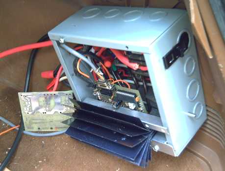
The new motor controller with "fan"
heatsink, 12 - 120 amp MOSFETs, PIC 16F690 microcontroller (socket)
and IR2130 MOS gate driver chip, mounted in the wiring box with 200
amp breaker, motor filter "run" capacitors, and... wires! A
bare motor controller PCB is to the left.
Of course, now that the PCB is done (and once the
software is done), the motor controllers can be duplicated pretty
easily.
Electric Hubcap Motor Factoids:
* One small but powerful hubcap motor supplied with 30(?)
volts has the power to drive a motor vehicle to city driving speeds
(up to 60-70 Km/H or so on level ground) instead of using the gasoline
or diesel engine.
* Most installations are expected to use two, for
left-right wheel balance and better, balanced, regenerative
braking.
* Only the car's wheel turns. The only moving part in the
motor is a thrust plate to keep the stator centered on the
wheel.
* The virtually frictionless magnetic link to the wheel
magnifies useful power by transmitting it all directly to the wheel.
There's no losses from a transmission or gears, it requires no gear
shifting or other attention by the driver, and it's
quiet.
* Permanent magnet synchronous motors also have the
highest intrinsic efficiency of all electric motor families, further
leveraging the efficient power transfer. As a guess, one might perhaps
expect up to 50% greater range than other (geared) electric motor
systems from the same energy, and correspondingly better performance
for the same kilowatts of electricity used by the motor.
* Installation requires no connections with or changes to
the car's existing mechanical components and systems.
* When not in use, the motor has no more effect on the car
than any other 35 pounds of luggage.
* The motor sticks out just 4" from the wheel or a
couple of inches past the fender, less protrusion than the outside
rear view mirror.
* The RPM with 13 inch wheels is about 10 per one
kilometer per hour of speed, that is, 450 RPM at 45 Km/Hour. Most
electric motors prefer much higher speeds, but the "Hubcap"
has good low RPM torque and power. 120 Km/hour is just 1200 RPM, a
stately pace for most electric motors but a good upper range for the
"Hubcap".
* The rotor is a 10 inch steel disk brake disk mounted on
the wheel lug bolts, 6 poles using 6, 12 or 18, .5" x 1" x
2" NIB supermagnets, glued and-or bolted on.
* The stator is a similar 10 inch brake disk (but with
cooling vanes), with 9 epoxy cast coils bolted to it, each of 60 turns
of #14 wire, in 3 phase "Y" configuration. Magnetic flux is
axial.
* A unique design breakthrough is that the stator coil
iron is strips of regular nail gun finishing nails in the coil cores
instead of custom die cut iron laminate sheets. With this and no axle
or other moving parts, the motor is simple enough to make at home, or
the coils could be wound by machine and cast, for super economical
mass production. Individual coils can be easily replaced.
* The motors dissipate their waste heat via air cooling,
avoiding the complexity of liquid cooling systems. There's maximal
coil air exposure and heat sinking with the magnets blowing air in
front of them, an air scoop on the front of the fairing and air guide
vanes, plus a temperature actuated electric fan in case all else is
insufficient at low motor RPMs that don't move much air and high power
(eg, climbing hills and mountains).
Motor Controller Factoids:
* The controller switches the DC power from the battery
onto three power wires that go to the motor's stationary magnet coils,
in a six state drive sequence timed to continually push/pull the
supermagnets on the rotor around in one direction.
* Three optical sensors looking through slots on the rotor
tell the controller the rotor magnet positions, to time the
switching.
* The amount of torque is controlled by pulse width
modulation of the power, proportional to depression of the accelerator
pedal beyond "neutral". Reverse torque to slow the motor
(regenerative braking) is provided by differently timed pulses
proportional to the release of the accelerator pedal above its
"neutral point".
* A reverse switch switches the signal polarities to
reverse the push on the magnets.
* In accelerating, the motor uses energy from the battery.
In decelerating, the motor generates energy, which goes back into the
batteries.
* The microcontroller chip in the motor controller is the
"brains" of the switching system, reading also motor
temperature, car speed and direction, and battery
voltage.
Turquoise
(Ni-La) Battery Project
September Detailed
Report
Once again I have had limited time to spend on the
batteries. There's progress but nothing definitive to report.
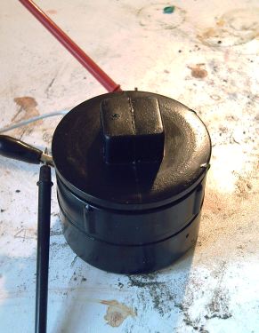
The most brilliant (and seemingly obvious) thing I
did do to simplify testing of new ideas was to make a small sealed
battery container of ABS pipe fittings, with a screw-on lid and the
terminal wires poking out the sides through tight fitting holes.
Theoretically I can now just dump out electrode formulations and try
others instead of making a whole new sealed battery every time.
Currently it's bubbling out at one of the wires, but the concept is
good.
A resealable test battery case,
wherein new formulations can be tried and then
dumped out.
And, it appears I've managed to change some
acetaldehyde (made last month) into an acetal ester. Lanthanum
chloride has good "lewis acid" properties that enable this
to happen, so I added some HCl to the negative electrode powder to
turn some of the La(OH)3 into La(Cl)3, then added the
acetaldehyde.
Then I added agar agar, stirred, cooked and then
refrigerated it to gel it. The intent is to "glue" the
negative electrode materials into an inert ion and electron conducting
"cheese" that one may hope won't deteriorate over many
charge-discharge cycles.
A study of "standard reduction potentials"
at http://www.webelements.com/compounds/ reveals that lanthanum seems
to have the most desirable electrochemical characteristics and price.
Furthermore, the lanthanum [as La chloride] can change the
acetaldehyde into acetal ester. I bought lanthanum originally with the
idea of simply copying Ni-MH batteries, but it seems to be the right
stuff for something better!
Battery KWH, Vehicle Range
and Cost per Km
(main stats in brief?... just read the bold
print.)
When attempting to anticipate vehicle range with any
given batteries, I've been using a GM EV-1 figure I saw somewhere that
showed the EV-1 as using 230-250 watt-hours per mile. I was assuming
that the EV-1 would have been somewhat lighter than a typical small
car, since it had no gas engine stuff and an aluminum frame. That
would somewhat counteract the higher efficiency of the Elactric Hubcap
motor, so I just used 250 WH/mile as a rough round figure.
However, I've looked up the actual EV-1 GVW and I
find it was originally 2900-3100 pounds with the lead-acid batteries,
which weighed 1200-1300 pounds. (Different web sites seem to have
varying figures.) The later Ni-MH gave it a longer range, but it was
only 200-300 pounds lighter, making the car around 2700 pounds.
This figure is around 500 pounds heavier than,
say... my Toyota Tercel Wagon. With 150 pounds of batteries (assuming
100 AH, 36 volts) and 50 pounds of motor and wiring in my car, call it
300 pounds lighter. If mileage is approximately inversely proportional
to weight, and if the low RPM Electric Hubcap PMSM is about 1.5 times
as efficient as a high RPM induction motor operating through a gear,
my mileage should be about 1.7 times that of the EV-1. Instead of 240
watt-hours per mile, it should use 145.
Thus, just three 100 amp-hour, 12v, deep cycle
lead acid batteries (=3.6 KWH, =150 pounds) should provide around 25
miles, or 40 Km, maximum electric range (though it's best not to
completely discharge lead-acid batteries). This is much better than
the 15 miles the EV-1 would get. Double the range with two sets if
desired. (300 pounds is still just two passengers worth of
weight.) With a very small car, even better figures could apply. Of
course, all this remains to be put to the test, but it looks
promising.
One can compare lead-acid battery operating costs
to gasoline. If the batteries got 400 cycles of life with about 25
Km driving per cycle, that's 10000 Km on a set of three batteries. Add
2/3 of a cent per kilometer for the actual electricity (@ 6 c/KWH):
$67. If those batteries cost $100 each, that's $357 for 10000 Km on
Pb-A batteries or 3 cents per kilometer. If the car on gas gets 10
Km/L and the gasoline is 1.40 $/L, gas for 10000 Km would cost
$1400 - over four times the overall cost of running on electricity
(excluding two oil changes and other gasoline engine periodic
maintenance, etc).
Environmentally it should be remembered that
although lead is toxic, recycling car batteries into new batteries is
standard practice - the lead doesn't end up in the environment.
Gasoline exhaust goes straight into the air. Thus, the idea that
lead-acid batteries are worse for the environment than gasoline seems
untrue. Perhaps cost per kilometer is a good indicator of
environmental impact as well as economic sensibility.
Similar or slightly better mileage figures should
apply to 100 amp-hour (or maybe better - up to 150 AH) Turquoise
batteries (6" x 6.5" x 12.5", 24 volts), except that
they'll cost more initially, weigh 1/4(?) as much, and running them
right down isn't expected to shorten their "indefinite" life
expectancy... in short, they should have no worries. Over
"indefinite" periods, cost with Ni-La or other
"ideal" batteries approaches $67 for 10000 Km.
I may be disillusioned if I actually try to run the
car with lead-acid batteries, but poor though they may be, as used in
a plug-in hybrid with limited electric range, and gasoline
"backup" for longer trips, the figures above indicate we'd
all save a lot of money by driving electrically.
A Stanford University report* shows over 75% of
trips as being under 20Km and 50% of all total daily driving as being
under 50Km. If the vehicle can be plugged in at the common usual
destinations (home, work...) then at least the bulk of one's driving
can be electric.
Nickel-lanthanum batteries could fill the bill for
an all-electric vehicle, almost tripling the range over nickel-metal
hydride -- with efficient direct drive wheel motors extending that by
a further 50%!
* Document: ev_battery_assessment.pdf ,
downloaded from somewhere or other.
http://www.turquoiseenergy.com
Victoria BC