Hi,
You're receiving this newsletter because you
asked to hear of updates or news of my "green" energy
projects in Victoria BC (ocean wave power, a motor system to make
"any old car" into a plug-in hybrid, and better large
batteries) or because I thought you'd be interested. If you don't want
any more, please reply and let me know. It isn't my intent to send
unwanted "spam".
Regards, Craig
Turquoise Energy
Ltd. News #9
Craig
Carmichael
November 1st 2008
Contents:
The Month in Brief
(overview... summary... the short version!)
Or, here's the Super Short
version!
* Electric Hubcap Motor Moves Car!
* Batteries start to Charge!
* Promising New Battery Chemicals!
BC's Goals? - an
editorial comment
Proposed First
Electric Hubcap
Motor Making Class/Workshop
(...January?)
Electric Hubcap Car Drive
Project, Long, Detailed Report
Turquoise Battery Project, Long,
Detailed Report
The Month in
Brief
Everything seemed
close to fruitition at the end of September and yet nothing much could
be claimed for results. October got better!
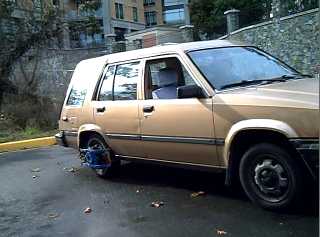
Car pulling out on 36 volts Electric
Hubcaptm
power
(movie URL below)
On the 6th, after
sending the September newsletter, I glued six more magnets onto the
car wheel rotor. It look quite impressive -
"industrial".
But it didn't
seem to increase the propulsion at 24 volts. Worse, the motor
controller burned up - again - when I tried to roll the car. That was
a bad moment.
I made a new motor
controller and a couple of mechanical improvements and on the 20th I
tried it out with 36 volts. The car moved on level pavement, if
only slowly.
Movie
Clips
At perhaps
1500-2000 RPM, this wheel has never before turned this
fast!
The pivotal
event!
(extra
footage - the remote's "Stop" didn't turn the camera off.)
The torque and power can and
will be improved, but it looks like "all wheel drive", four
motors, will probably be needed rather than just two, to have
satisfactory power for highway speeds and hills. The essential plan
for making "any old car" into a plug-in hybrid still
works.
Having recently
located pre-made parts for most items, the motors will be amazingly
easy to make! Most of the effort will instead be installing them,
including mounting brackets, wiring and controls.
The direct
drive concept, now shown to work, is easily the lightest and most
efficient possible means to propel a vehicle: 2/3 as much horsepower
is required and it'll have half again the electric range per battery
of everything else. That's better than anything you can buy today at
any price. It's the future of vehicle propulsion.
Also on the evening of
October 6th, I finally tried some things that worked - not exactly as
I'd envisioned them - and got a battery to charge.
Then on the 9th, I
tried making a "Ni-Ni" battery
[1.1v] as an experiment. That charged too! That chemistry would be
quite a simple battery to make at home, with energy density similar to
Ni-Cd or Ni-MH. Then I found calcined zinc
oxide. With a higher voltage than the others [1.6v+], Ni-CaZn cells are almost equally simple,
promise considerably better energy density, and will cost less. La-CaZn holds considerable promise for even
better density, but is more complex to make.
My batteries still
need much work.
BC's
Goals?
What does it say about
the effectiveness of our society if the will to go to sustainable
electric power runs from the premier on down, and yet there seems to
be provided no channel for action or practical support to nurture and
sustain vital breakthroughs in furtherance of our goals when once they
make their appearance? It seems the province is now offering
"savings of over $6000 on the purchase of a new fuel efficient
car", but not $6 assistance to develop a means for eliminating
the bulk of the fossil fuel usage of the entire province over the next
few years.
Most talented but
unpaid innovators give up and get a job. When by some miracle they
manage to develop a valuable product on their own puny resources, it
is grabbed and used by industry, usually without recompense. (Less
than 1% of inventors make good money off their inventions. Musicians
with original work are much better protected.) Is that the process of
energy innovation the premier is trying to promote?
The whole face of
transportation will be changed forever by better batteries, and by the
Electric Hubcap type of drive motor and what automakers will
eventually turn it into.
I put the wave power
on hold because it doesn't look like anybody will make the slightest
use of even a superb, practical demonstrated working unit - or even
permit it to be deployed and connected - even though west coast wave
power would be 1/2 the price of the Site C dam, environmentally
benign, and could be phased in incrementally.
Here are new
industries, new Boeings or Microsofts in potential. Who will grab them
and take the lead: BC where they were invented, or Europe or China? It
seems to me that currently we drift with no plan while everybody -
government, business, investors, and the public - waits for somebody
else to do everything for them.
First
Proposed Class - Workshop
When is a good time to offer workshops?...
The batteries are certainly not ready. On the other
hand, the prototype Electric Hubcaptm works,
the design will now have improvements based on the deficiencies and
strengths revealed in the tests, and it will be a very easy
motor to construct and to duplicate.
On balance I think it would be a good idea to hold
an Electric Hubcap making and installing workshop/class with a number
of sessions in the upcoming months, perhaps starting in January.
The Electric Hubcap is not a finished product. More
fabrication and trial of design variants would be of value. The
microprocessor controls aren't ready and motor operation will be quite
basic (drive power and forward/reverse, no regenerative braking or
displays...) until they are.
On the other hand, it would seem enough is known now
to make reliable, workable motors and run cars with them, and if I on
my own very meager resources try to get all the desired things tested
alone, it could take a year or more and meanwhile nobody's driving on
electricity, whereas if workshop participants each try a variant or
two, much would be learned before the sessions end, the participants
would have electric drive cars and know how to make them, and I would
have some funds to continue the R & D for the batteries and the
computer controls, which is otherwise about to go into very low gear.
(When ready the computer controls would be provided at cost to
workshop alumni.)
So if anyone is eager to electrify their vehicle,
please let me know! I'd be very pleased to run an early workshop
series when about 4 or 5 people are signed up. The motors made at the
workshop will certainly be better than my prototype, which has at
least moved the car!
Here is a description of the proposed program as I currently see
it, details subject to change:
Course
Overview
* Instruction session:
working principles of the Turquoise Energy Electric Hubcaptm
vehicle drive motor and its ancillary components, as applied to
creating a plug-in hybrid car and other useful
applications.
* Motor making workshops as required to
assemble the motors.
* Instruction session: motor controller
details; simple controls details.
* Workshops: assembling the motor controllers
and wiring boxes, and the simple controls.
* Instruction session: various aspects of
installing the motors, and the computer controls.
* Motor installing workshops as required to
get the cars going.
* Additional instruction and workshops as
required to complete projects.
* Followup session(s) when computer controls
are complete: install computer controls.
Participants should be
mechanically inclined. Experience with design, fabrication and
installation in any fields of metal working, mechanical, auto
mechanics, electrical and electronics are assets. Participants are
encouraged learn principles of construction during the workshops and
do work on their own if and as convenient. Work will be inspected and
discussed by me and by the other participants. Creative thought in
adaptation to specific vehicles and improvements to systems is
encouraged.
The object of this course is
twofold:
(a) to have the participant
create his or her own Electric Hubcap equipped super
efficient plug-in hybrid vehicle or other similar motor installation
of choice, and
(b) without obligation, to
provide a trained nucleus of people to who are familiar with this
exciting and promising new technology, the future of
propulsion. They'll not only save on gas,
they'll be engaged with the cutting edge of electric transportation
technology.
I haven't specified the number of workshops for each phase:
there's lots of new things here and it's hard to quantify how long the
jobs will take. We'll continue for one or as many sessions as it takes
to satisfy the class. Installating things in the car is the most time
consuming part, and is likely to vary considerably by vehicle.
There'll be three instructional manuals (or subjects
in one large manual) to accompany the workshop: Making the Electric
Hubcaptm Motor, Making the Electric
Hubcaptm Motor Controller, and
Installing the Electric Hubcaptm Drive System
in a Vehicle. Writing of these proceeds apace.
The tuition fee for the workshop program will be
$2000, and the parts cost will be $900 per motor. That includes most
everything: the motor, controller, wiring box, and cables. But (what
else is new?): batteries not included.
Unless they can be scaled up in diameter, magnets
and coils, four motors would seem the necessary number to
satisfactorily propel a typical smallish car.
I think I should order/buy the parts, paid for in
advance by the participants (at cost - but see below). That should
bring some quantity discounts, and the materials would all be on hand
when the workshop sessions commence. Perhaps the money for materials
(as well as the tuition fee of course) can be made tax deductable and
PST exempt - that would lower the costs for participants.
I was surprised the materials for each complete motor
installation cost so much when I added them all up. Anyone who wishes
to provide some of the supplies themself is certainly welcome to do
so. I will of course need to know what you are bringing before I order
the parts. Particular items to provide that can save money are listed
below.
Particular items to provide that can save money:
* car disk brake rotors - Honda Civic(?) rotors (10.25"
diameter with a hub of 5.5" inside diameter) appear to be
ideal for typical 4 lug bolt wheels. As rotors are perhaps $40 and two
are used per motor, that's $320 for four motors. Anywhere that does
auto brake repairs should have used rotors going into the garbage can.
They don't have to be in great condition, though a pretty flat face to
mount the magnets on is desirable.
* winding and casting or varnishing/baking your own coils. If the
coils are $20 (though that price is not ascertained yet) and you can
wind your own for $8, at 9 coils per motor that saves $432 for four
motors. It is however quite a time consuming operation that would have
to be mostly done outside workshop time after initial guidance and
practice.
* Finding your own heavy copper wire, 200 amp circuit breakers,
capacitors, wiring boxes and other electrical parts. Heavy #4 battery
cables and #6 or #4 "cab tire" cables to the motor cost in
the upper tens of dollars per motor. 200 amp breakers for the motor
controller boxes (preferably aluminum boxes for heat dissipation) all
add up.
The Electric
HubcapTM Vehicle Drive Motor
October Gory
Details
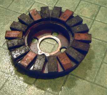
The first thing to try to get more torque was
obviously to fill the rotor with magnets. It had twelve, and I'd
spaced them so six more could be added between. The rotor stuffed with
magnets had a really "industrial" look that said "part
of a Motor"!
But then I tried it out. At 24 volts, the jacked up
car wheel spun vigorously up to 680 RPM, the same speed as before and
with about the same amps, and on the ground the car again didn't seem
to quite want to move. I started it slowly down the street with the
gas engine and turned on the juice, using a potentiometer on the
passenger seat instead of the one on the gas pedal. At
"max", one could feel vibration from the magnetic thrust,
creating a bit of propulsion, but after a few seconds at "max"
a transistor blew and burned the circuit board. Lots of smoke and
flame. There seems to be nothing to tell you when you're crossing into
the red zone until that sudden "BANG".
I must say that was a bad moment. I reflected that
perhaps after all I'd simply made everything just a bit too small and
underpowered to succeed, and that maybe I should just abandon the
whole motor project and leave the future of vehicle propulsion to
somebody with more resources.
But the motor was undamaged, I hadn't tried 36 volts
yet (it would have been the next test), and I had one more motor
controller circuit board and could soon rebuild the controller with a
few more transistors and (doubtless) a new MOSFET driver chip.
I had to give it a shot with 36 volts. If that would
at least budge the car on flat ground and not burn out, a second motor
should bring the power up to "driveable".
I limited the PWM duty cycle to 80% max hoping to prevent
another controller burn-out and made a couple of needed mechanical
improvements. I finally spun the jacked up car wheel on October 20th
after previous testing on the bench. With 36 volts, it spun up to what
seemed like 1500-2000 RPM. 2000 RPM would be 200 Km/Hr, though of
course the only load was the wheel. Accelerating, the motor may have
drawn 60-80 or more amps, and it seemed to drop to around 40 amps once
it was up to speed. (I suspect it was more on startup, probably well
over 100, but the meter was too slow responding to catch it.)
Then I took the car to a level cul-de-sac and tried
driving it. On level pavement there were a couple of non-starters -
until I remembered first to take the car out of gear... and then to
turn off the parking brake.
Then the car moved, though only slowly. One could
hear the coils buzzing with the PWM and feel the push and the sudden
small changes of force as the wheels turned and different groups of
coils turned on and off.
After driving just 3 or 4 car lengths (twice), I went outside and
felt the coils. They were very hot, some notably hotter than others.
Not smoking - yet - but obviously the wiring is too light. (#10 feed
wires & #14 coil windings - should increase those to about #6 &
#12 or #11.) Then I felt the heat sink and the transistors in the
motor controller, but they were only warm. The new MOSFETs certainly
seem to generate less heat. The car moved, nothing blew up or burned,
and I got a bit of footage! That was enough for one day!
What factors might have limited the performance?
1. the 80% PWM duty cycle.
2. a 6mm or so air gap. (It was supposed to have been 3mm -
something must have changed with the last ball bearing changes!)
3. The timing might not have been optimum. A bearing seal
(previously mutilated) fell out and ravaged the optics just at the end
of the spin-up tests. I had to replace a phototransistor and just
guessed at the timing/rotation when I replaced the optics board. Poor
timing makes higher currents and less effective force.
4. The light wiring cable to the motor (#10) probably had
significant voltage drop.
What might improve things in a notable way?
1. A thinner air gap between the magnets and coils. That may make
considerable improvement. I've heard you can run PMSM motors with
quite wide air gaps, but no doubt that really means 1/16th or 1/8th of
an inch instead of 5/1000ths, not the 1/4 inch the car moved with.
With the new trailer axle hardware for the future models, it will be
possible to set the gap very thin without danger of things hitting
each other, but a certain amount of gap improves electrical efficiency
and prevents the coils from gradually weakening the
supermagnets.
2. The computer controls, when they're done, will be set to
safely limit the maximum PRM duty cycle at the low RPMs that burn
things out, and allow 100% at higher speeds, so the power will
increase somewhat with speed.
3. Larger rotors. The rotor diameter provides the leverage radius
from the center of the wheel that the magnetic forces push from. Vis:
if you have a ten foot pole attached to the wheel, you can easily push
the end of the pole to turn the wheel and move the car. With a ten
inch pole instead, you may not be able to turn the wheel at all.
The rotor size is the biggest advantage of the axial
flux design - the effective magnetic diameter is almost three times
that of a comparable radial flux motor.
The new rotors for the "production" model
are 10-1/4" instead of the prototype's 9-1/2", for about a
ten percent torque increase.
A 12 inch or even larger diameter would provide room
for more sets of coils and magnets, acting at again a larger radius
from the center of the wheel. I would imagine this variant would be a
good size for a heavier vehicle -- or if one perhaps hopes to outfit a
smaller car with just two motors instead of four.
4. Electromagnet coils with larger iron cores, eg, 2" round
donut cores instead of 1" x 2" almost rectangular ones:
three square inches of iron facing the magnets instead of the two of
the prototype. With the marginally bigger new rotors there should be
enough room. Bigger cores should broaden the magnetic field to the
rotor magnets for more torque.
And one might perhaps deepen the coil cores
from 1 to 1.25 or 1.5 inches if it seems useful, to fit even heavier
wire (eg #10), for more magnetism with less heat.
I think the basis for optimum performance lies in
these details.
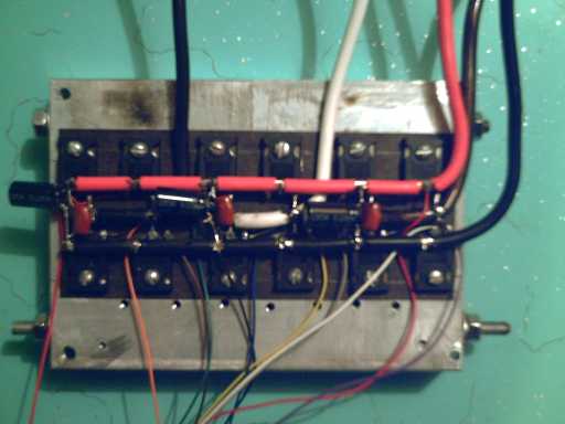
I didn't like the fact that the transistor had
burned a hole right through the circuit board in the 24 volt test. So
I started to rethink the layout. Again, why mount these high powered
components on a printed circuit board at all? I did it because the
original direct wiring was messy with six transistors, and would have
been a hodge-podge with 12. I cleared off the old heat sink, dumped
some of my new batch of MOSFETs on it, and started looking for an
intrinsically neater wiring layout. After some moving things around,
and finally bending and chopping leads to better visualize things, I
found one. The five heavy leads and connections (battery +, -, and the
three phase motor outputs) are short and direct. It's so simple you'd
think it was a natural, and indeed once I'd found it it was obvious,
but actually it took a lot of puzzling out. The backing insulation is
(ready for this?)... tarpaper. Cheap, takes heat, and makes good
contact without messy silicone heat conducting grease. How well does
it conduct heat? The most I can say so far is that the
transistors didn't feel warmer than the heatsink fairly soon after
moving the car.
The new MOSFETs are rated at 60 volts instead of 100
(still 120 amps) and have half the internal ON resistance (.0024
ohms). This means they generate half the heat.
The new rendition of the motor controller power
section. This moved the car.
The motor controller transistors are now doubled up,
which should theoretically be good for up to 240 amps and the circuit
breaker is 200 amps. But another transistor blowout attempting a test
on Halloween indicates the need either to further limit the maximum
power at low RPMs or else to at least triple the transistors. (or to
stay indoors on Halloween!) Since triple transistors and the same
power would probably result in soon blowing the breaker instead, the
first choice is probably the better.
I phoned an old electronics friend on the mainland
and I said I was doing a car motor. His first reaction was, "Oh,
popping MOSFETs, are you?" It would seem it's a given for this
sort of project.
Things will be eased when there's more than one
motor. Then the car should accelerate smoothly with moderate power
from each one, instead of painfully starting to roll slowly at full
power.
Also in one recent test, the three black filter
capacitors between the wires (photo above) popped, and have been
replaced by much heftier units from a motor shop. Across supposedly
steady DC lines, the transient spikes from the motor - which are after
all what the capacitors are there to filter - must have made enough
transient currents to blow the small ones.
Someone has an interesting idea for an all-electric
van: turf the gas engine, transmission et al, and mount the motors on
the inner ends of the CV axles. This has all the electromechanical
advantages of the direct drive approach, and it would have space for
multiple rotors and stators to gain any desired amount of power and
torque. In that case, the rotor and stator I made would be one of
perhaps two or even three for each wheel, essentially multiple motors
on one shaft. (One could perhaps even "stack" multiple
rotors and stators with no iron backing except at the end rotors, to
make a very light high powered motor: see my Turquoise Energy
MPMG generator stacked rotor-stator machine idea on the web at
http://www.sears.com/~craig .)
I'd visited Canadian Tire, Lordco and other auto
parts stores many times, and it's very frustrating. You know they have
lots of stuff, but it's in boxes in the back, and if you don't give
them a make and model of car, they have no way of looking it up, and
are mostly unwilling to even open any boxes. I was lucky to find the
brake rotors I did for the stator and rotor. Then, in the middle of
October, I found Thomcat Trailers in Langford, where there are various
axles, hubs, rotors and bearings right there where you can piece
things together. After some puzzling with what could work with what, I
worked out an excellent looking set of standard parts to make the
hubcap motors from.
A week later I was walking by an auto service center
and looked at disk brake rotors in their garbage drums. (dumpster
diving for R & D!) There were some four stud rotors that were a
virtually perfect size, much better than the ones I'd been buying.
They're 10.25" diameter instead of 9.5" (a better fit for
the magnets and a bit more leverage radius for the magnetic torque),
and the center hub is bigger, in fact a perfect fit for the trailer
axles.
The motors don't need perfect new rotors. The
mechanics thought these were probably from a Honda Civic... now we
know what to look for at Midas!
And, seeing some trailer electric brake coils at
Thomcat gave me the idea of looking for pre-made electromagnets for
the motor instead of having participants wind them during workshops.
Though these seemed a good size and shape, the wire was too fine with
too many turns. But that started a search for them. A hundred dollars
extra for coils is cheap if it saves you from winding your own! I
didn't find anything suitable "off the shelf", but it may be
that a local motor shop will be able to wind them in quantity for a
reasonable price per coil.
With fine pre-made parts, the motor itself will
pretty much bolt together like a mechano set, including securely
fixing the entire motor right onto the wheel, dead center, by an axle
and bearings. This is a great improvement! As far as mounting the
motor, that just leaves fitting the two brackets that bolt to the
brake drum housing and come around the wheel, ahead and behind, upper
and lower. These meet the arms on the stator, now merely to hold it so
it can't spin.
The other major parts of the installation are
mounting the motor controller, driver controls, batteries, and doing
the wiring.
Fuzzy Logic
Somewhere earlier there was some mental lapse in my
logic. 100 amps feeding three parallel coils splits into 33 amps per
coil, not 100 amps each, where 33 amps through series coils is again
33 amps per coil. Thus, the motor with the coils wired in series
should in fact have performed about the same at 108 volts as it now
does at 36 volts with parallel coils. Operation-wise, there was no
good reason to switch. It should have moved the car about the same.
The question is academic first because I never got up past 60 volts (5
batteries), and second because it's changed and I won't go back.
Safety alone is worth $100 and a few extra pounds of
copper in the car for fat low voltage wiring. It's much harder to be
electrocuted on a damp day by 36 volts than by 108 or 120 volts, and I
expect lots of people to be making and installing their own motors. (I
unthinkingly grabbed that 60 volt connection just once to disconnect
it. Nothing happened. At a higher voltage, or in the rain, one might
not get a second chance.)
But there's more: the low voltage MOSFETs generate
much less heat, and the minimum number of 12 volt batteries needed to
drive electrically goes from 9 to 3, an economical figure and a
smaller weight and bulk to put into the car. Having even 6 batteries
instead of 9 far more than makes up for the extra weight of copper
wire.
Electric Hubcap Motor Factoids:
* Two small but powerful hubcap motors supplied with 36
volts should have the power to drive a motor vehicle to city driving
speeds (up to 60-70 Km/H or so on level ground) instead of using the
car's engine. Four are needed for highway travel and steep
hills.
* The motors weigh about 50 pounds each.
* They are very easy to make.
* Most installations are expected to use two or four, even
numbers providing for left-right wheel balance and better, balanced,
regenerative braking.
* Only the car's wheel turns. The only moving part in the
motor is an extended axle that ties the stator firmly to the wheel.
Brackets extending around the wheel from behind prevent the stator
from spinning.
* The virtually frictionless magnetic link to the wheel
magnifies useful power by transmitting it all directly to the wheel.
There's no losses from a transmission or gears. It requires no gear
shifting or other attention by the driver, and it's
quiet.
* Permanent magnet synchronous motors also have the
highest intrinsic efficiency of all electric motor families, further
leveraging the efficient power transfer. Roughly, one might perhaps
expect up to 50% greater range than other (geared induction motor)
electric motor systems from the same energy, and correspondingly
better performance for the same kilowatts of electricity used by the
motor.
* Installation requires no connections with or changes to
the car's existing mechanical components and systems.
* When not in use, the motor has no more effect on the car
than any other 35 pounds of luggage.
* The motor sticks out just 4" from the wheel or a
couple of inches past the fender, less protrusion than the outside
rear view mirror.
* The RPM with 13 inch wheels is about 10 per one
kilometer per hour of speed, that is, 450 RPM at 45 Km/Hour. Most
electric motors prefer much higher speeds, but the "Hubcap"
has good low RPM torque and power. 120 Km/hour is just 1200 RPM, a
stately pace for most electric motors but a good upper range for the
"Hubcap".
* The rotor is a 10 inch steel disk brake disk mounted on
the wheel lug bolts, 6 poles using 6, 12 or 18, .5" x 1" x
2" NIB supermagnets, glued and-or bolted on.
* The stator is a similar 10 inch brake disk (but with
cooling vanes), with 9 epoxy cast coils bolted to it, each of 60 turns
of #14 wire, in 3 phase "Y" configuration. Magnetic flux is
axial.
* A unique design breakthrough is that the stator coil
iron is strips of regular nail gun finishing nails in the coil cores
instead of custom die cut iron laminate sheets. With this and no axle
or other moving parts, the motor is simple enough to make at home, or
the coils could be wound by machine and cast, for super economical
mass production. Individual coils can be easily replaced.
* The motors dissipate their waste heat via air cooling,
avoiding the complexity of liquid cooling systems. There's maximal
coil air exposure and heat sinking with the magnets blowing air in
front of them, an air scoop on the front of the fairing and air guide
vanes, plus a temperature actuated electric fan in case all else is
insufficient at low motor RPMs that don't move much air and high power
(eg, climbing hills and mountains).
Motor Controller Factoids:
* The controller switches the DC power from the battery
onto three power wires that go to the motor's stationary magnet coils,
in a six state drive sequence timed to continually push/pull the
supermagnets on the rotor around in one direction.
* Three optical sensors looking through slots on the rotor
tell the controller the rotor magnet positions, to time the
switching.
* The amount of torque is controlled by pulse width
modulation of the power, proportional to depression of the accelerator
pedal beyond "neutral". Reverse torque to slow the motor
(regenerative braking) is provided by differently timed pulses
proportional to the release of the accelerator pedal above its
"neutral point".
* A reverse switch switches the signals to reverse the
push on the magnets.
* In accelerating, the motor uses energy from the battery.
In decelerating, the motor generates energy, which goes back into the
batteries.
* The individual motors and controllers have minimal
digital logic and will run connected to controls having nothing more
than a 555 timer to generate the PWM signal (connected to the gas
pedal) and a forward/reverse switch, though connection to a
microcontroller "brain" at the front of the car is needed to
provide the more sophisticated features such as dynamic
braking.
* The microcontroller chip in the motor controller is the
"brains" of the switching system, reading also motor
temperature, car speed and direction, and battery
voltage.
Turquoise
Battery Project
October Gory
Details
I started this project in January knowing no more
electrochemistry than most people. But in the endeavor one learns, and
I'm gradually catching on and finding some very good ideas and
substances.
A Better Positive Electrode Material
The challenge: the low energy density of nickel
oxyhydroxide as a positive electrode limits the energy density of the
whole family of Ni-xx rechargeable alkaline batteries. Finding a
better oxidizing electrode material seems to need going beyond the
simplest reactions and the commonest elements.
I got enthusiastic about using lanthanum hydroxide
as a reducing (negative) electrode, as it wasn't too expensive and had
a -2.80 volts potential (or -2.90 depending where you look) and moves
3 electrons per molecule, promising higher voltage and higher
amp-hours cells. What I didn't know then was that water starts
separating into ions (H+ & OH-) and even into H2 and O2 gas at
this voltage level, so you can't use it in a water based electrolyte.
About two volts is the effective limit.
Then I thought I could separate the cell into two
halves with a graduated "voltage ramp" (dope the electrode
separator sheet with ferric oxide or osmium powder) so the water never
sees the whole voltage at any given point, but I finally realized that
each half still has to be under two volts. The ramp idea may reduce
self-discharge, and may provide the potential for cells up to four
volts instead of two, but under two volts on each side. Barring
figuring out some strange non-water based electrolyte, the energetic
lanthanum hydroxide to lanthanum reduction would seem to be out.
:(
But perhaps the lanthanum could instead be used in
an oxidizing (+) electrode.
I found many of the "rare earths" will
form a tetravalent oxide, LxO2, instead of Lx2O3. A lanthanum
hydroxide to this "overcharged" oxide should have a good
energy.
But this reaction wasn't listed for lanthanum
itself. Another reaction is lanthanum chloride to lanthanum
perchlorate, which should have very good energy. Complications arise
in that perchlorate is more reactive towards organic substances than
inorganics, so some organic catalysts are called for.
The first battery made up with this, with the
sintered monel-lanthanum powder gelled with agar agar in acetal ester
solution does seem to charge, but even with all the trouble I've gone
to the case has a leak, so the (promising) results are inconclusive so
far.
(Dysprosium should probably be better at oxidizing
than lanthanum, but I have the lanthanum.)
The
Nickel-Nickel Battery
and
Nickel-Calcium Zincate Battery
October
Experiments
In the process of working on the Ni-La battery, I
decided to discharge the cell by reversing the polarity. It charged up
backwards as La-Ni to over a volt, and supplied some useful current to
a load. That's when I started clueing in to lanthanum as a positive
electrode - and nickel hydroxide as a negative one. I looked up the
reduction reaction of nickel hydroxide and noticed it looked quite
similar to cadmium:
Ni(OH)2 + 2H+ + 2e-
<==> Ni + 2H2O [-0.72V]
This of course complements the nickel oxidation
reaction usually used:
Ni(OH)2 + 2OH- <==>
NiO(OH) + 2H2O [+0.52V]
Total would be 1.24 volts - call it 1.1 volts under
load.
Cadmium [hydroxide] is -0.824V, but cadmium is more
expensive than nickel and otherwise objectionable for such a small
gain.
Why, then, had no one made a nickel-nickel battery
simply using nickel hydroxide for both electrodes? It would seem an
obvious thing to try, but I couldn't find any mention of such a thing
on the web, including nothing explaining why it wouldn't work.
Perhaps companies start with the idea of replacement
"AA" and "D" cells, and decided 1.1 volts just
didn't quite cut it? Then because it wasn't mentioned anywhere, no one
thought of it for big batteries?
Having the chemicals et al on hand, I decided to try
it.
It started charging fine! But the usual bubbles on
my open experiment indicate the cell has to be sealed.
What would it cost? To make a long list of
calculations short, around 150 $/Kg for materials. That's not too much
more than for lead-acid, and (probably) would last for ages.
That was in early October. Then I found calcined
zinc oxide! Zinc has a higher voltage than nickel, 1.2v instead of
.72, and "calcium zincate" may be even higher. And, it's
half the price of nickel hydroxide!
1.6 volt Nickel-Zinc batteries have been made, but
when recharged, the zinc crystals tend to grow through the electrode
separator sheet and short out the battery, limiting the cycle life.
(This seems to be the usual fate of Ni-Cd's too, in my electronics
experience.)
I can see several ways or potential ways to prevent
this, and the calcium may possibly mitigate the process regardless.
Worst case, one makes the batteries so they can be dismantled and
serviced, eg, replacing the separator sheet with a clean one. This
would obviously be impractical for AA cells, but perhaps not for big
electric car batteries. But, I don't really expect that none of
the possible methods to avoid the problem in the first place will
work!
Even with a nickel positive electrode, the zincate
offers better energy density than Ni-MH and Ni-Cd owing to the higher
voltage of the reaction, and the cells are still under the two volt
ceiling even if the "voltage ramp" should prove
ineffective.
Again, the nickel-zincate battery should be an easy
one to make at home.
Now all we need are leak proof containers. The think
I may have the ansswer: I'm going to try stuffing the batteries into
small salad dressing or similar bottles, using rubber test tube
stoppers to seal the tops. These would have two holes, one for each
electrode terminal. The original caps will have the middles cut out
and will be screwed back on as compression rings to prevent the
stopper from working its way out or popping out under pressure. If the
batteries become very pressurized, or if they freeze, the sides will
simply bulge out.
And, they should certainly be cheap! (I can see
myself now, digging through blue boxes on the boulevards!)
http://www.turquoiseenergy.com
Craig Carmichael
250 384 2626
Victoria BC