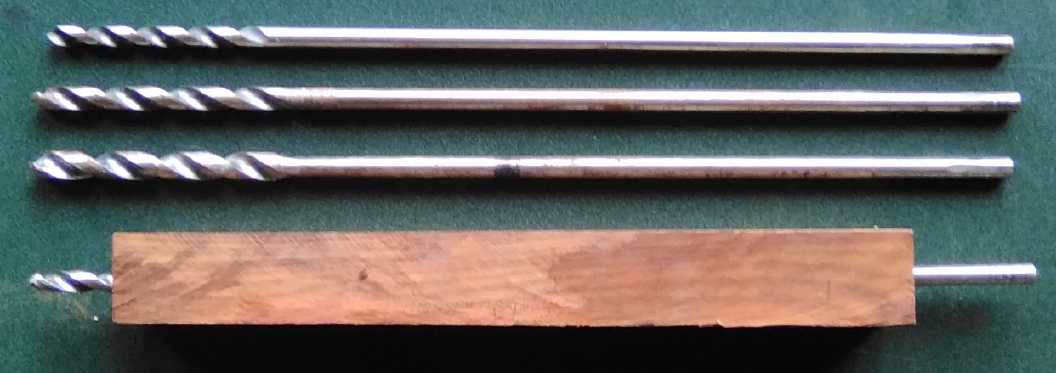
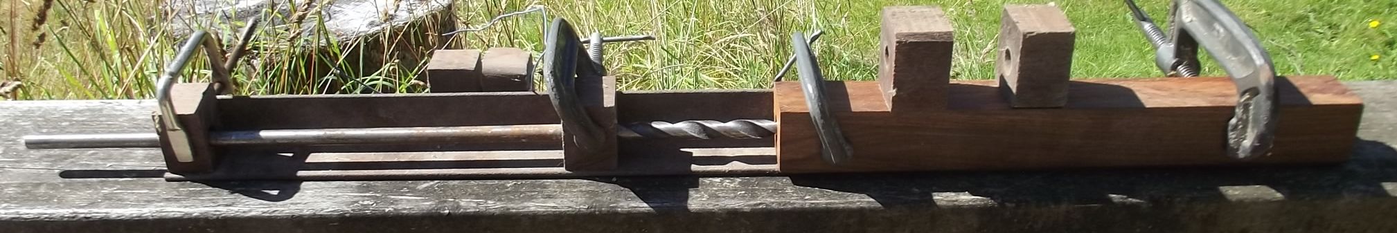
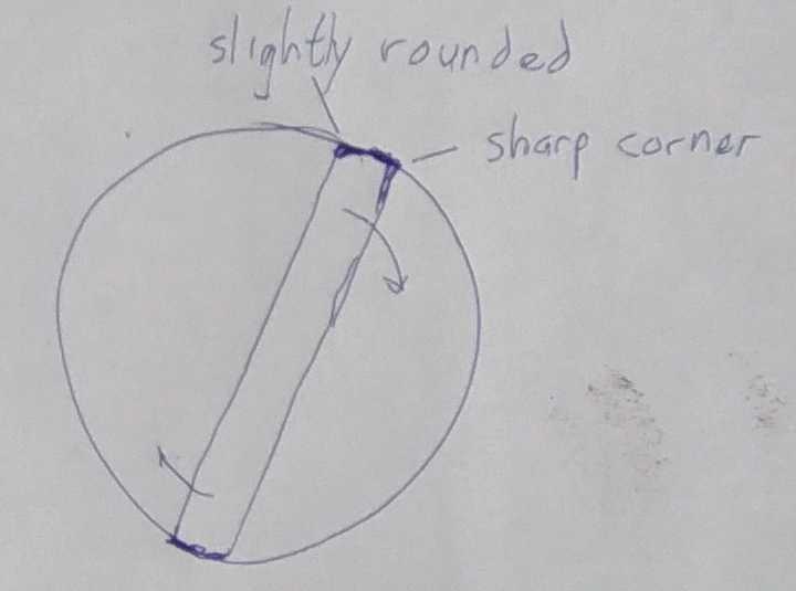
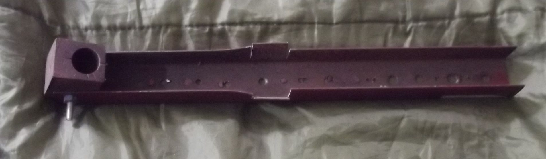
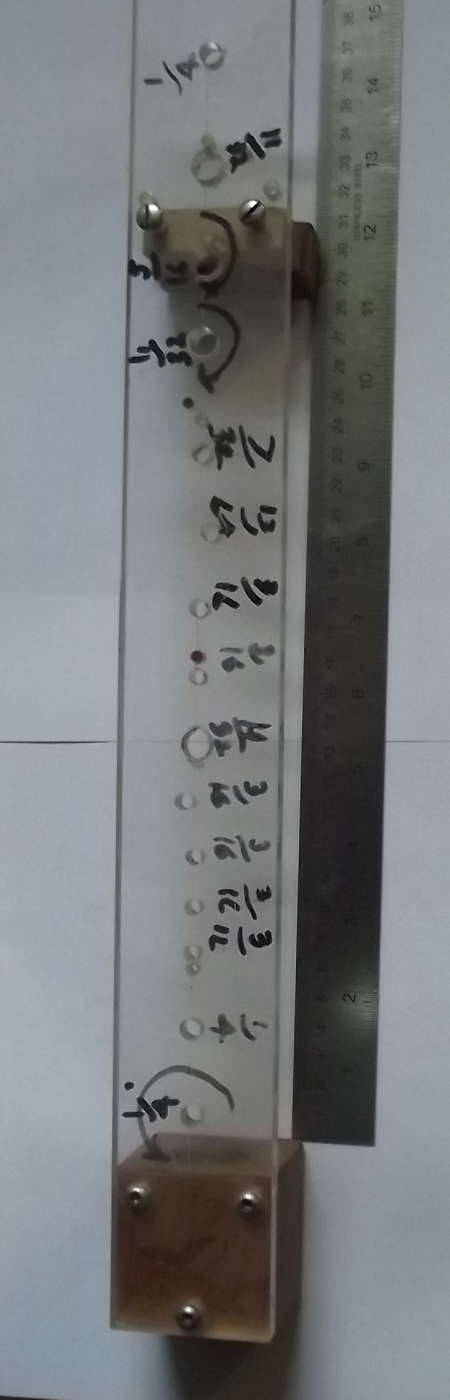
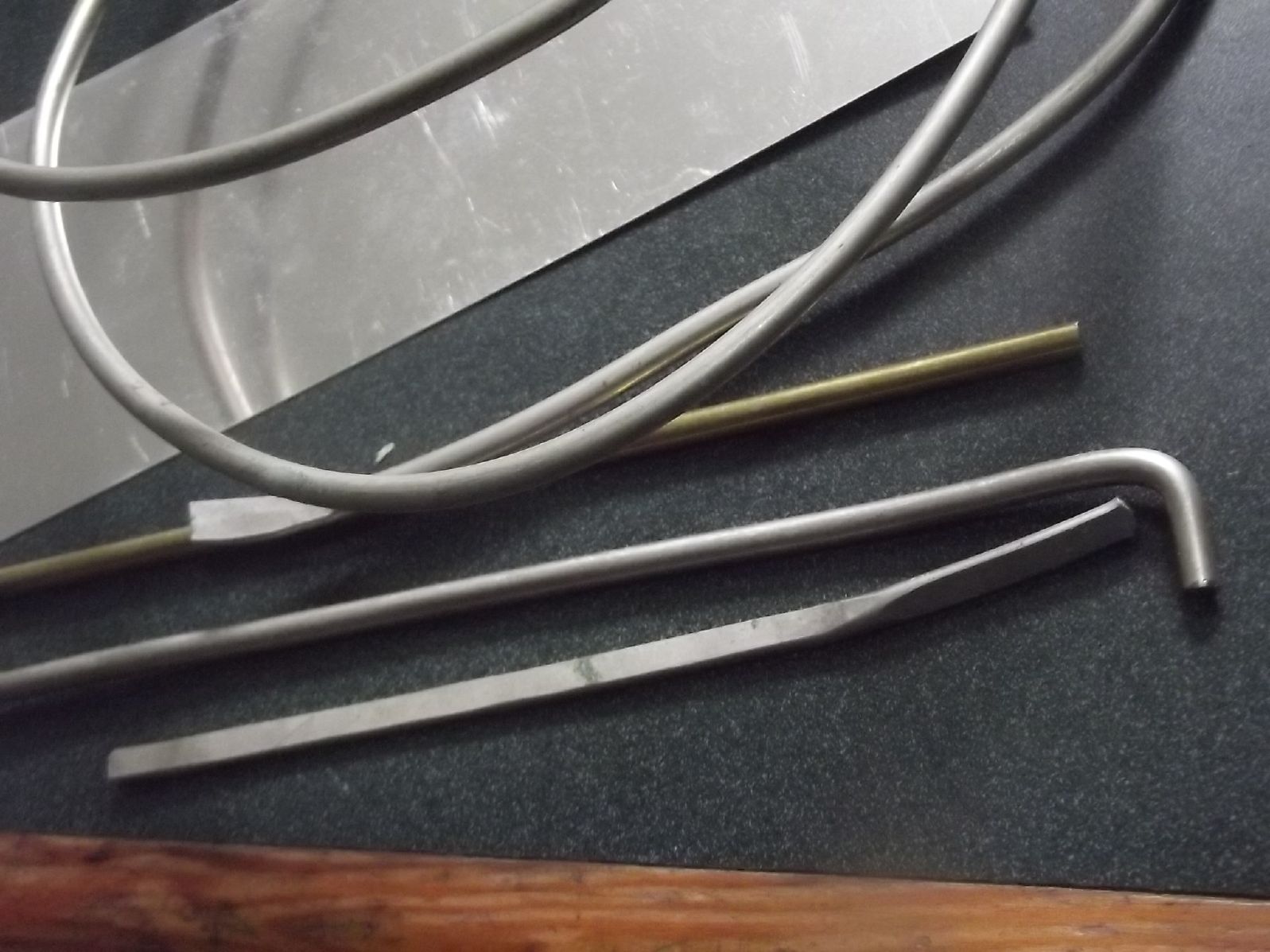
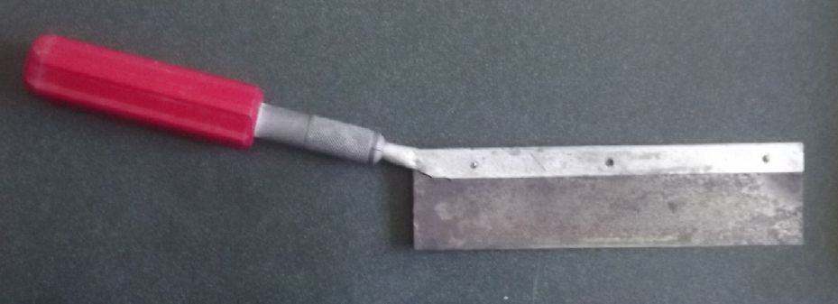
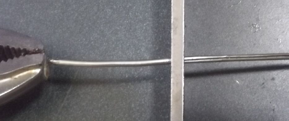
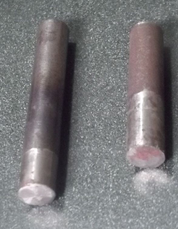
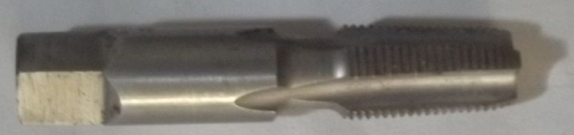
 I made the body bore reamer from a
piece of 1/8 x 3/4 inch mild steel bar about 450mm long. From the
slight "shoulder" (image below) the shank part ends and the
reaming part starts. The reaming part is long enough to go right
through the body bore and do the bottom end cleanly. Two corners
along the edge of the reamer are sharpened (at 90 degrees to the
face) to scrape out the bore to the desired profile when one turns
it clockwise. The other two edges are slightly rounded off to
follow the inside curve of the bore, providing enough support that
the reamer scrapes smoothly without "jitter", but not binding.
I made the body bore reamer from a
piece of 1/8 x 3/4 inch mild steel bar about 450mm long. From the
slight "shoulder" (image below) the shank part ends and the
reaming part starts. The reaming part is long enough to go right
through the body bore and do the bottom end cleanly. Two corners
along the edge of the reamer are sharpened (at 90 degrees to the
face) to scrape out the bore to the desired profile when one turns
it clockwise. The other two edges are slightly rounded off to
follow the inside curve of the bore, providing enough support that
the reamer scrapes smoothly without "jitter", but not binding.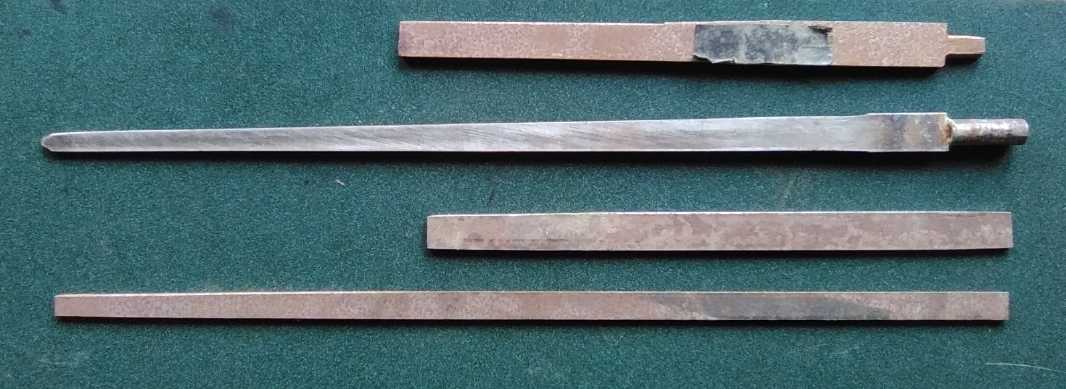
| Measured at: Distance from Shoulder mm |
Width Across mm |
Width Diagonal mm |
| '0' (@2 mm) |
16.80 [17.3] |
17.16 |
| 50 |
16.03 [16.1] |
16.31 |
| 100 |
15.00 |
15.33 |
| 150 |
13.80 |
13.98 |
| 200 |
13.12 |
13.34 |
| 250 |
11.93 |
12.30 |
| 300 |
10.90 |
11.22 |
| 350 |
10.30 |
10.69 |
| 380 |
10.20 |
10.35 |
| Measured at: Distance from Lower Shoulder mm |
Width Across mm |
Width Diagonal mm |
| '0' (@2 mm) |
18.00 |
18.52 |
| 50 |
17.47 |
18.16 |
| 100 |
17.35 |
17.83 |
| 120 |
17.15 |
17.75 |
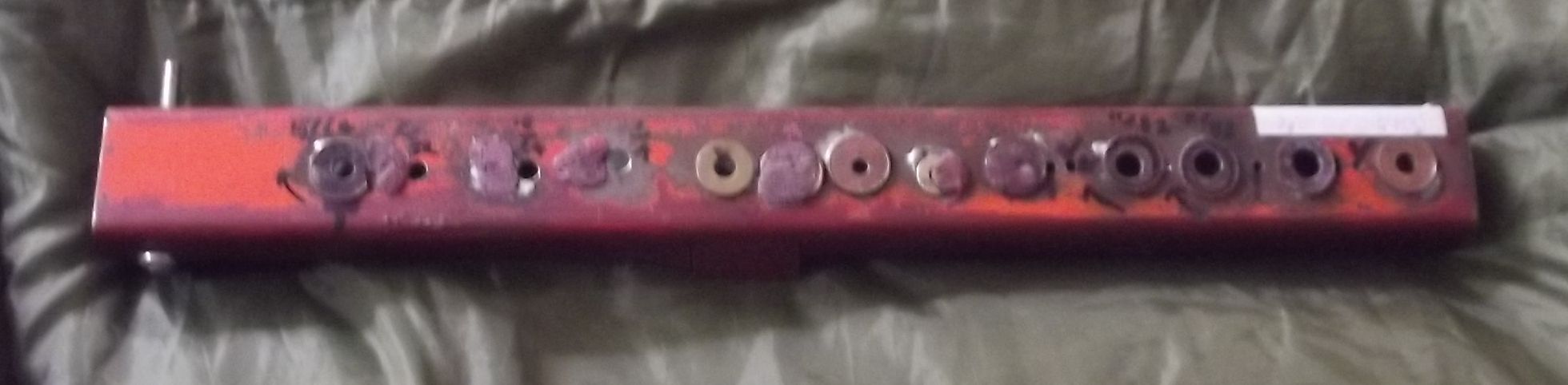
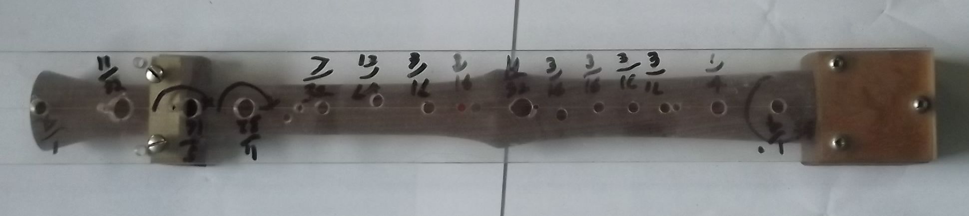
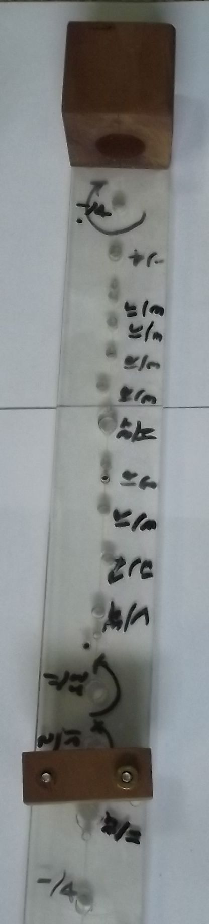
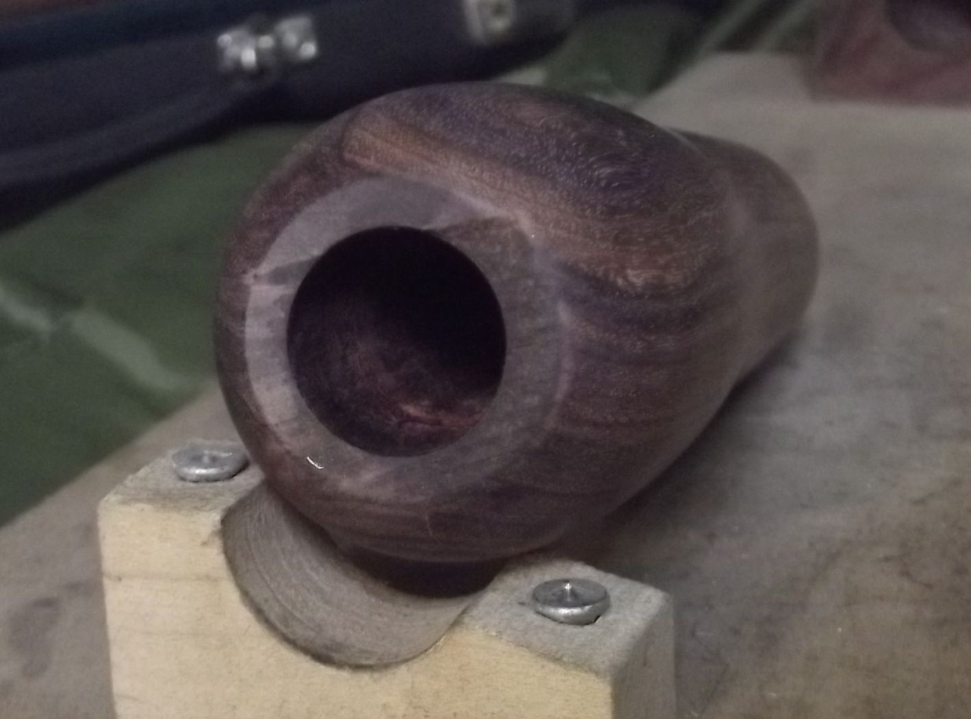
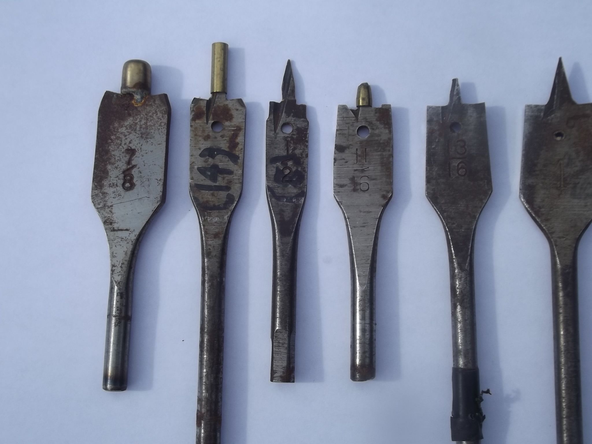
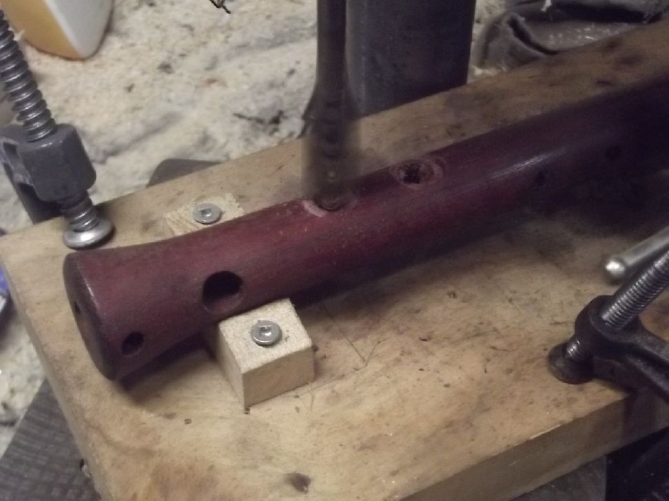
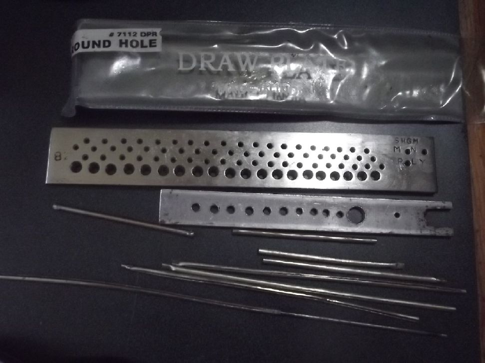
 In sizing the hole drills,
it was intended that the holes never be drilled too large, which
would make notes too sharp. Rather, they may be a bit undersize
(note flat) so that removing a bit of surrounding wood will raise
the pitch until it's in tune. Then they can be reamed out bit by bit
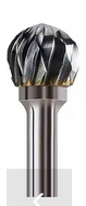
from inside with a 'dremmel moto tool' burr bit. The burr bits I
used were small, shaped round and inverse cone. The small burrs fit
though the hole and so are able to ream it from the inside face so
that the outside face of the hole is unchanged.
In sizing the hole drills,
it was intended that the holes never be drilled too large, which
would make notes too sharp. Rather, they may be a bit undersize
(note flat) so that removing a bit of surrounding wood will raise
the pitch until it's in tune. Then they can be reamed out bit by bit
from inside with a 'dremmel moto tool' burr bit. The burr bits I
used were small, shaped round and inverse cone. The small burrs fit
though the hole and so are able to ream it from the inside face so
that the outside face of the hole is unchanged.| Finger (Notes when hole is the top open hole,
closed) [Rotation from in-line with other fingers - degrees] |
Distance in mm |
Hole size in inches |
| Left Hand |
||
| Thumb (G, F#) [180] | 18.5 |
1/4 |
| 1 (F#, E) |
44.5 |
1/4 |
| (E, Eb) |
68 |
3/16 |
| 2 (Eb, D) |
82 |
3/16 |
| (D, C#) |
97.5 |
3/16 |
| 3 (C#, C) [left ~ 4 mm but usually drilled
straight down] |
114 |
3/16 |
| Right Hand (mostly!) |
||
| "4" - index finger (C, B) (B, Bb pipe) |
131.5 |
11/32 |
| (B, Bb) (B, Bb pipe) |
152 |
3/16 |
| "5" (Bb, A) |
173.5 |
3/16 |
| "6" (A, G#) [may be in-line or ~4 mm right
(see text), but drilled straight down] |
196.5 |
13/64 |
| "8" (G#, G) [0° - in line] (LEFT little finger, double key) |
220.5 |
7/32 |
| "7" (G, F#) [75°(?) right] (RIGHT little finger, bottom lever double key) |
255 |
5/16* (?jig says 11/32?) |
| (F#, F) [75°(?) right] (RIGHT little finger, top lever double key) |
280 |
5/16* |
| "8" (F, E) [0] (LEFT little finger, double key) |
310.5 |
11/32 (Try 5/16*, undercut? |
| BELL STOPPED (E, Eb, or E, D with "D"
tube) |
347 |
1/4 |
| Pillar Key Set |
Distance Down (top hole, mm) |
Distance Down (bottom hole, mm) |
Angle from in-line with finger holes
(degrees) |
| Eb - Db |
63 |
158.5 |
90° to right |
| G - E |
135.5 |
318 |
90° to left |
| F# - F |
231 |
287 |
25° (?) to right |
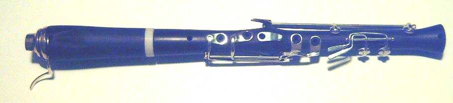
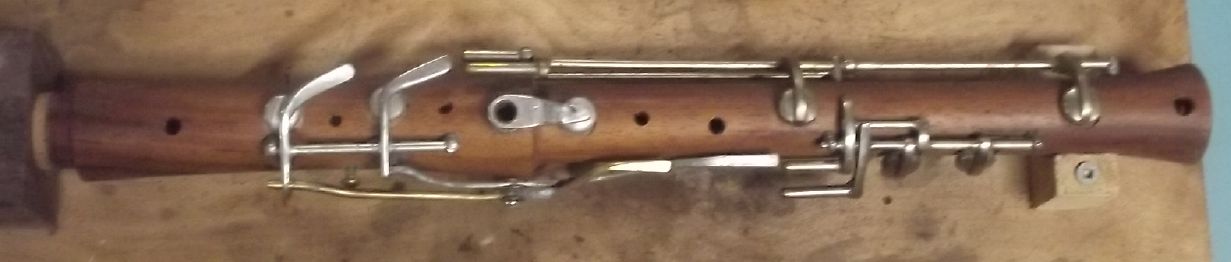
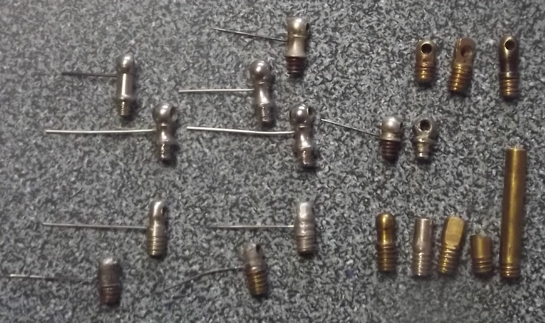
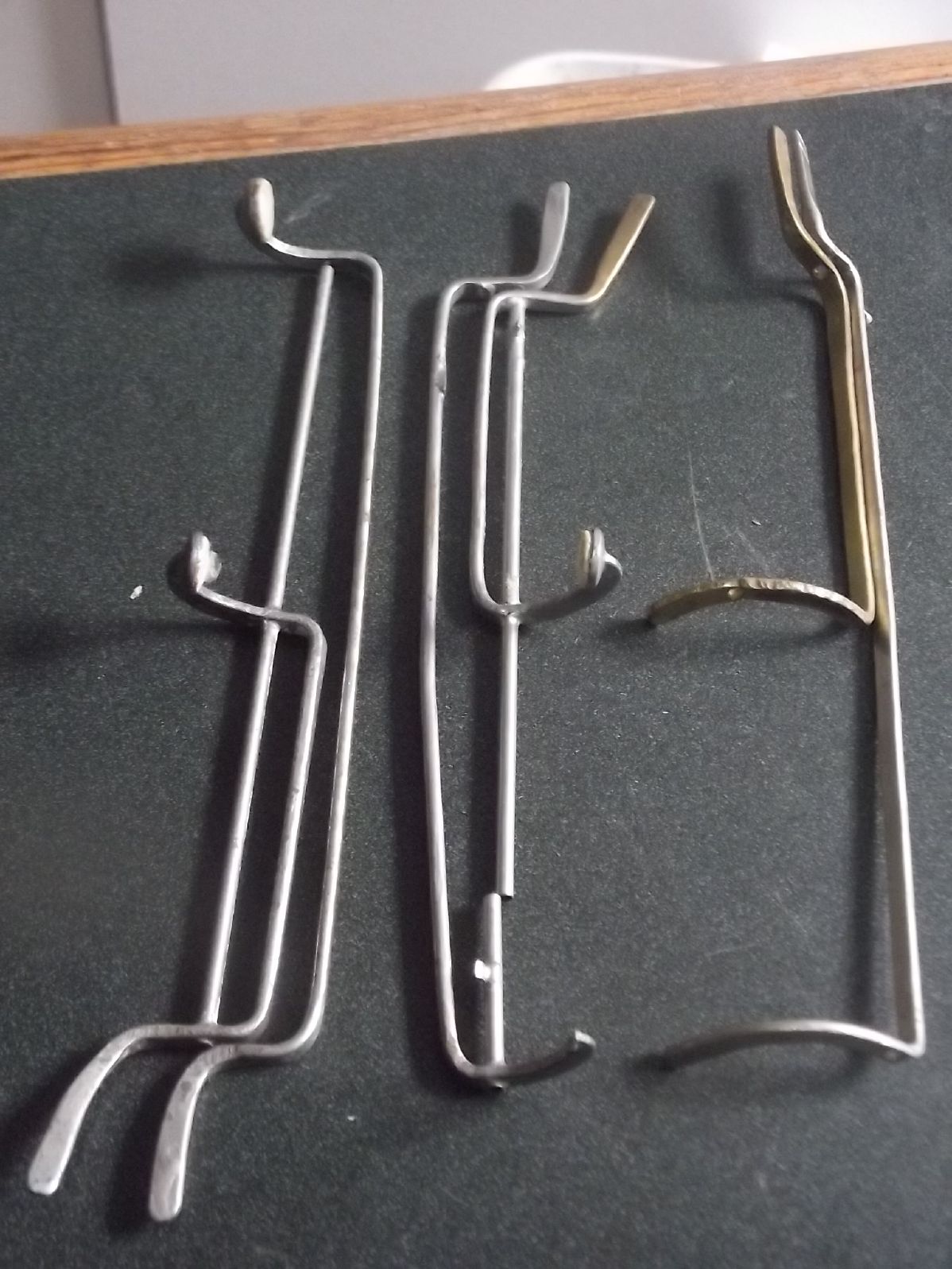
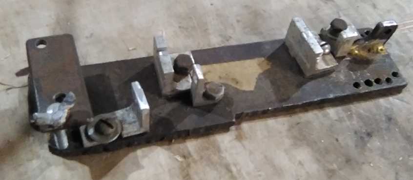
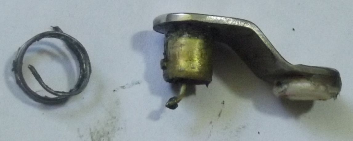
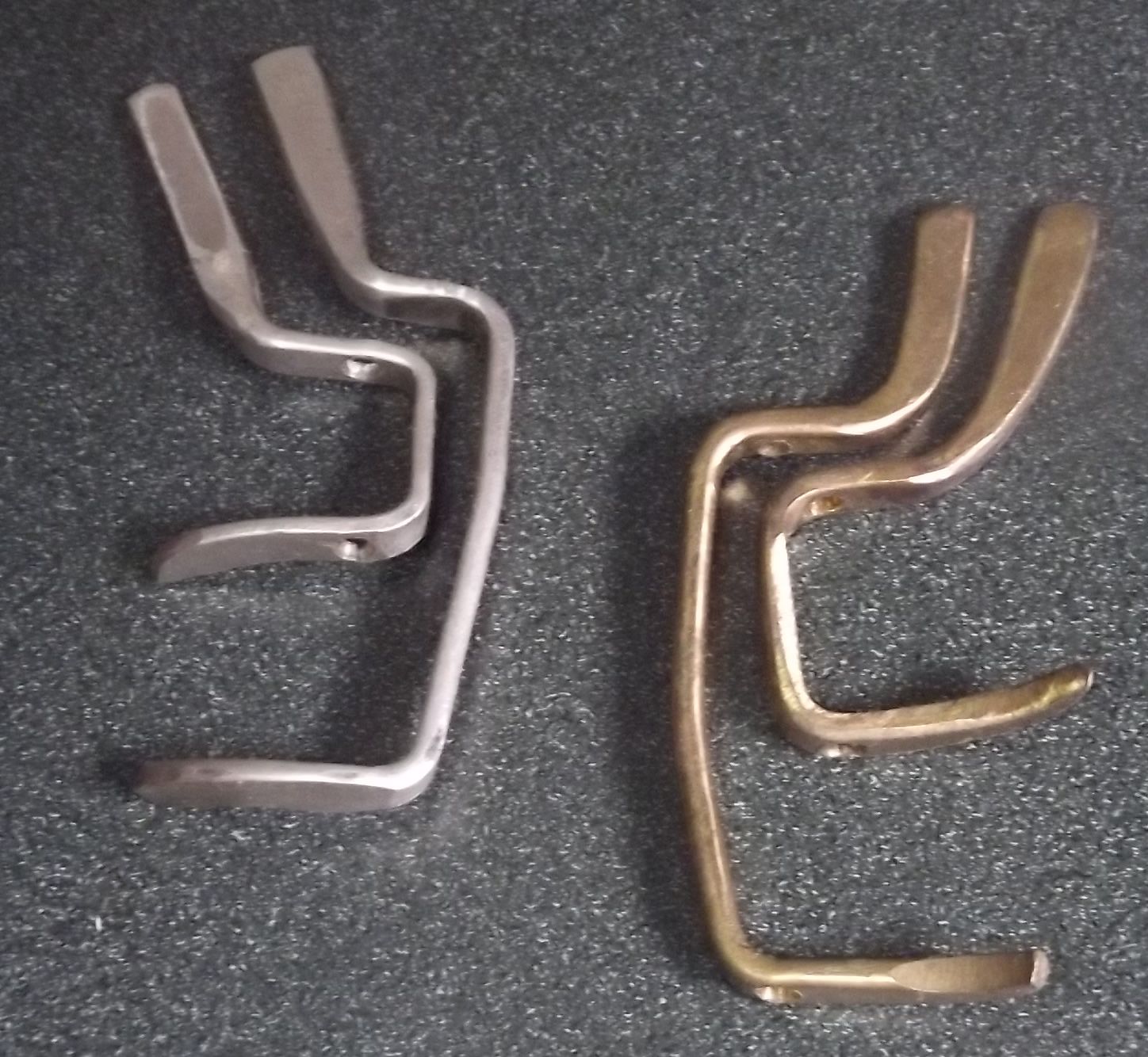 But after that I started forming the
moving part of the keys out of just four pieces - the axle tube,
the pad cap, the spring rest, and a single "bracket" piece
something like a "U" (or "[") with a finger rest tail, bent around
in three dimensions to form the finger rest and the rest of the
parts between and holding the pad cap. This takes all the twisting
strains. With this arrangement the tubes have no tendency to
twist, and the two or three soldered joins take very little
strain. So I just used soft solder - the "modern" "silver bearing
solder" (tin alloy) often used in electronics. (Eg, Sn:Cu:Ag
93.6:4.7:1.7%), with resin core. Not to be confused with much
harder, high temperature "silver solder", made of various mainly
silver (Ag) alloys.) I did try to make a large common surface area
of solder join and to get more solder built up around the edges,
especially for the ring keys, whose finger pieces do take some
strain.
But after that I started forming the
moving part of the keys out of just four pieces - the axle tube,
the pad cap, the spring rest, and a single "bracket" piece
something like a "U" (or "[") with a finger rest tail, bent around
in three dimensions to form the finger rest and the rest of the
parts between and holding the pad cap. This takes all the twisting
strains. With this arrangement the tubes have no tendency to
twist, and the two or three soldered joins take very little
strain. So I just used soft solder - the "modern" "silver bearing
solder" (tin alloy) often used in electronics. (Eg, Sn:Cu:Ag
93.6:4.7:1.7%), with resin core. Not to be confused with much
harder, high temperature "silver solder", made of various mainly
silver (Ag) alloys.) I did try to make a large common surface area
of solder join and to get more solder built up around the edges,
especially for the ring keys, whose finger pieces do take some
strain.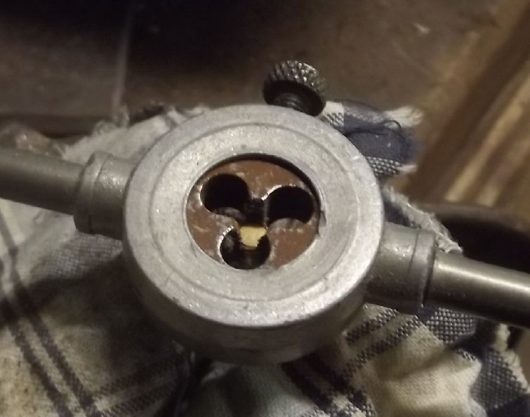
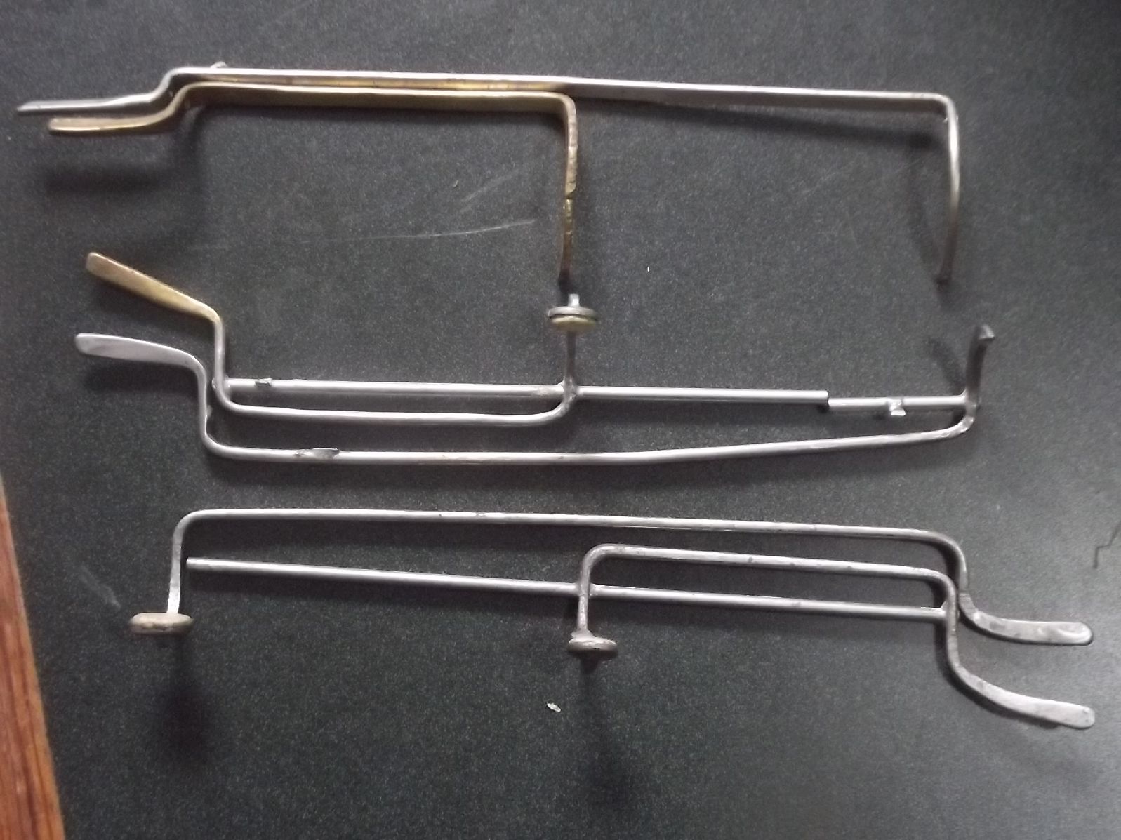
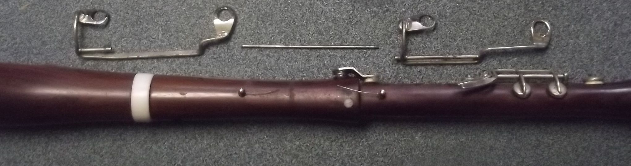
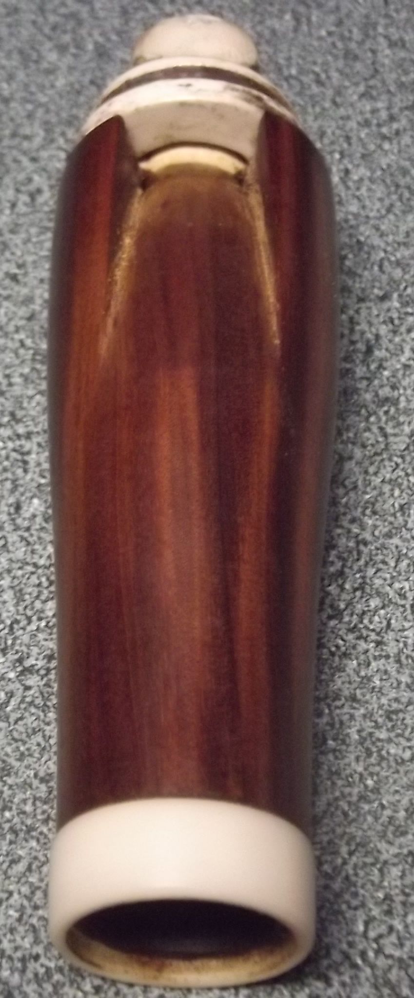
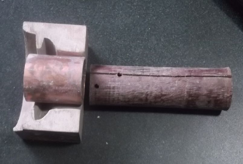
 The tube surround, lever and
Bb pad cap I sometimes made from one piece, sometimes
using one of the pad cups. These (as best I can remember) were
all cut and shaped by hand. An 8 mm clarinet pad seems good; use
8 mm oboe pad for thinner.
The tube surround, lever and
Bb pad cap I sometimes made from one piece, sometimes
using one of the pad cups. These (as best I can remember) were
all cut and shaped by hand. An 8 mm clarinet pad seems good; use
8 mm oboe pad for thinner.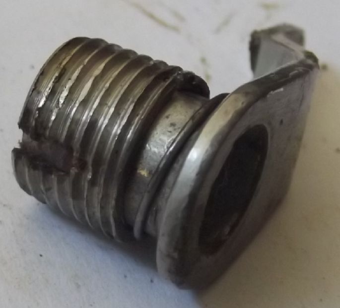 At first I cut the slot in the pipe
from the bottom. It does the job of preventing the key from
popping off. This particular tube stops when the spring is fully
compressed, which is just about the right point where the Bb key
closes. Great!... The tube surround, lever and
Bb pad cap I sometimes made from one piece of thick sheet
metal, sometimes using one of the pad cups. These (as best I can
remember) were all cut and shaped by hand. I probably punched or
drilled the hole for the tube first. I was using an 8 mm
clarinet pad (or an 8 mm oboe pad for thinner).
At first I cut the slot in the pipe
from the bottom. It does the job of preventing the key from
popping off. This particular tube stops when the spring is fully
compressed, which is just about the right point where the Bb key
closes. Great!... The tube surround, lever and
Bb pad cap I sometimes made from one piece of thick sheet
metal, sometimes using one of the pad cups. These (as best I can
remember) were all cut and shaped by hand. I probably punched or
drilled the hole for the tube first. I was using an 8 mm
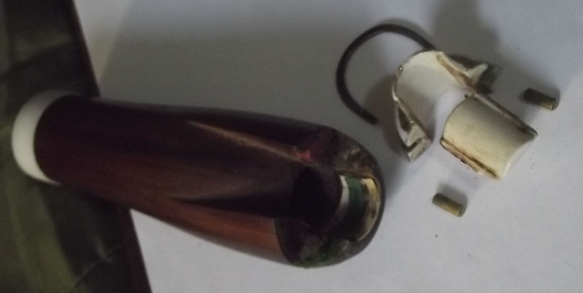
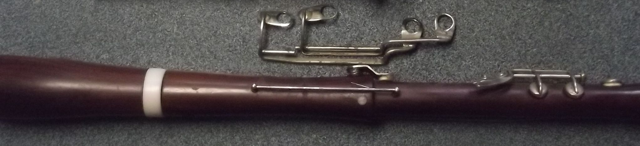
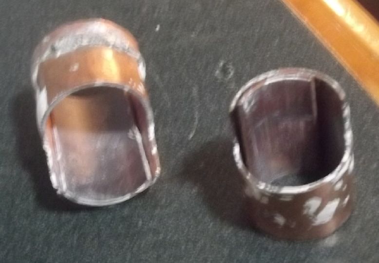
clarinet pad (or an 8 mm oboe pad for thinner).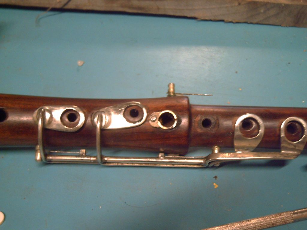 Okay, something new! Being
unsatisfied, I've just worked out a new way: screw a retainer
piece to the body of the instrument that covers the top of the
slot in the pipe. (The screw is 2 mm x 6 mm.) It could be made
as I've done this one, or with a slot so that it pivots one
way to keep it closed and nearby direction to open the slot to
remove the key. Or (tolerance being tight) it could be a
"washer" with an off-center hole, to be rotated until it
covers the slot without rubbing on the tube. There's not much
room, but it seems better.
Okay, something new! Being
unsatisfied, I've just worked out a new way: screw a retainer
piece to the body of the instrument that covers the top of the
slot in the pipe. (The screw is 2 mm x 6 mm.) It could be made
as I've done this one, or with a slot so that it pivots one
way to keep it closed and nearby direction to open the slot to
remove the key. Or (tolerance being tight) it could be a
"washer" with an off-center hole, to be rotated until it
covers the slot without rubbing on the tube. There's not much
room, but it seems better.
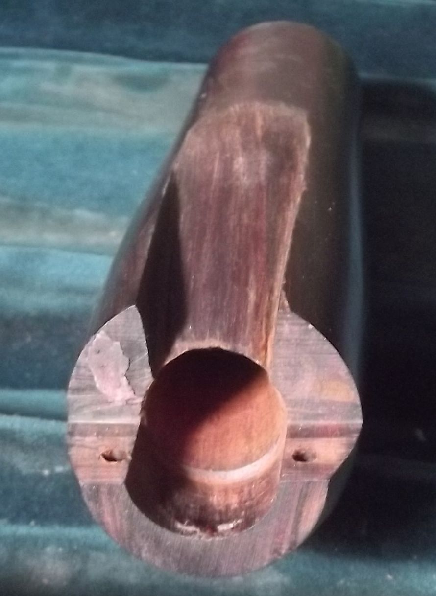
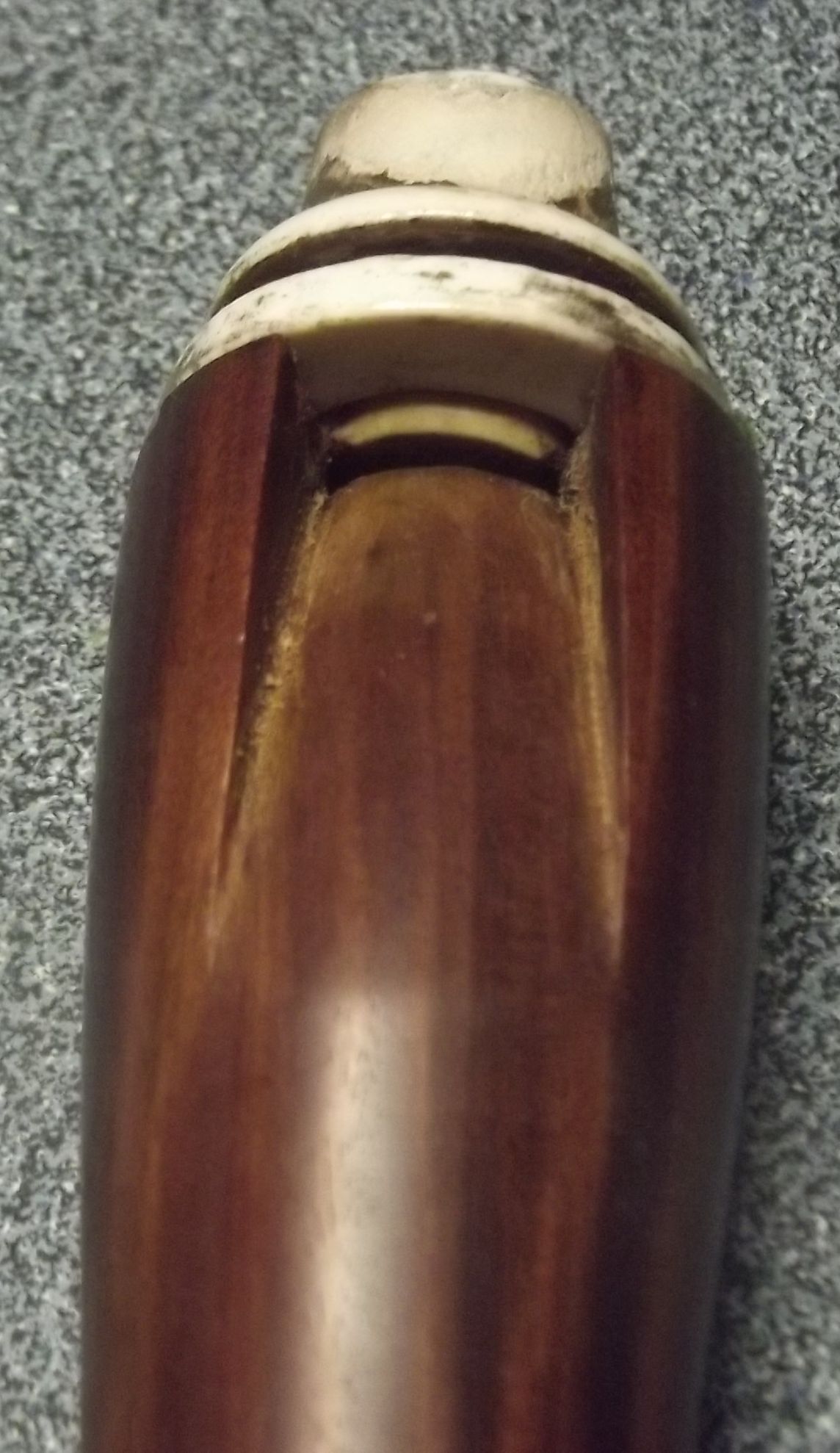
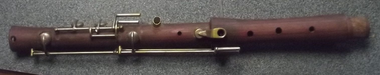
 One day I read that some bamboo
flutes were brought into tune by making a hole in the side near
the labium to sharpen the pitch. I made a mechanism, a push-lever
with a spring, pressed by the lower lip to open such a hole. This
was one of the two special, original inspirations for making the
supercorder, along with the dual B-Bb pipe/key. It worked,
which was exciting, but it was somewhat awkward. It didn't have a
really fine feel that a player wants. I thought about making a hole
directly closed by the lip, but it seemed like it would be an
awfully long hole. Was it even close enough to the labium to work?
Recorder windways (for alto size) are generally a couple of inches
long, and a quarter circle curve shape underneath. Obviously the
curve was just tradition and had no bearing on the sound. Did they
need to be so long? I cut that in half to an inch and changed the
outside shape to "squarish" so the lower lip could conveniently
cover a much shorter hole. It worked! Very nicely!
One day I read that some bamboo
flutes were brought into tune by making a hole in the side near
the labium to sharpen the pitch. I made a mechanism, a push-lever
with a spring, pressed by the lower lip to open such a hole. This
was one of the two special, original inspirations for making the
supercorder, along with the dual B-Bb pipe/key. It worked,
which was exciting, but it was somewhat awkward. It didn't have a
really fine feel that a player wants. I thought about making a hole
directly closed by the lip, but it seemed like it would be an
awfully long hole. Was it even close enough to the labium to work?
Recorder windways (for alto size) are generally a couple of inches
long, and a quarter circle curve shape underneath. Obviously the
curve was just tradition and had no bearing on the sound. Did they
need to be so long? I cut that in half to an inch and changed the
outside shape to "squarish" so the lower lip could conveniently
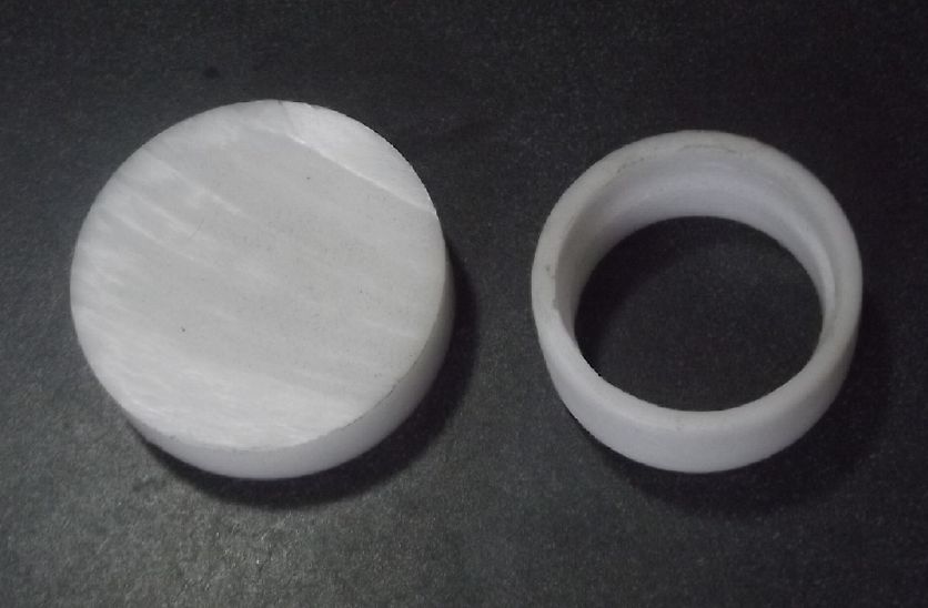
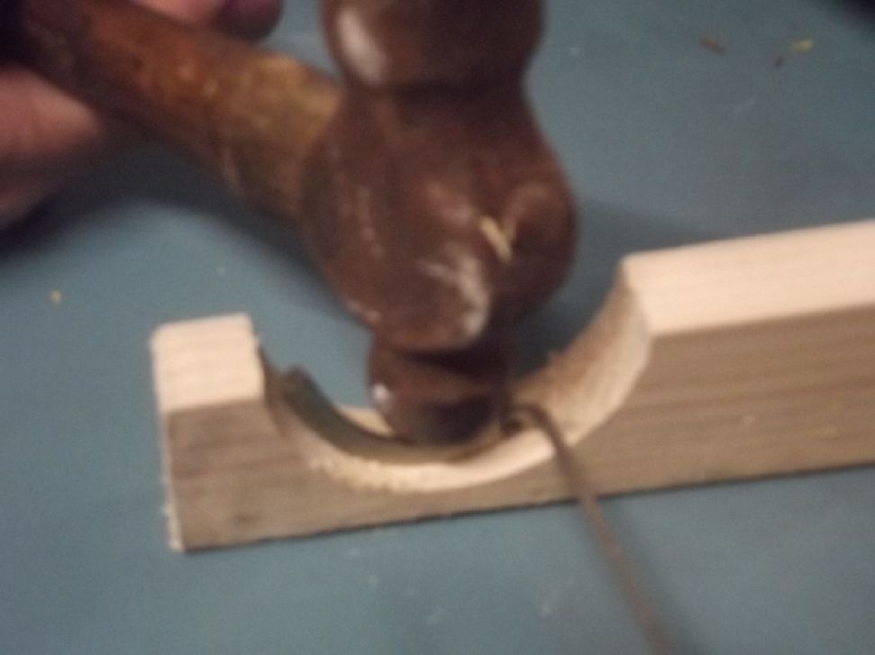
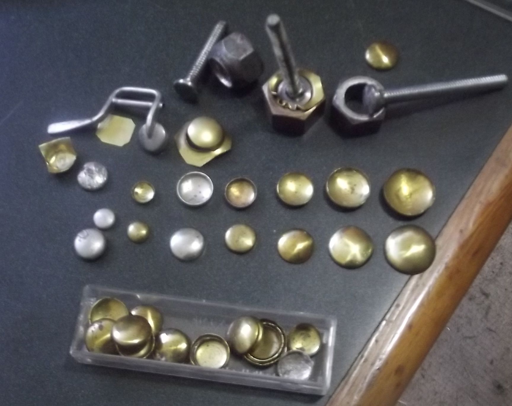
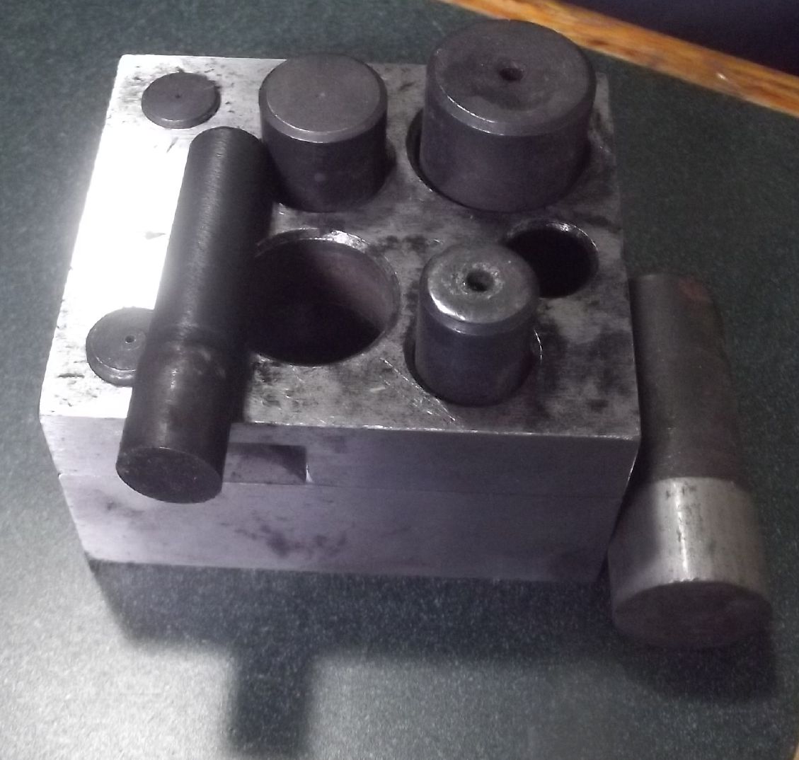
cover a much shorter hole. It worked! Very nicely!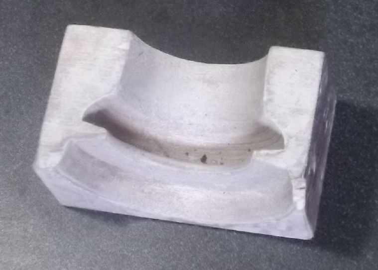 I made molds to shape the
porcelain beaks and blocks. In coming up with the shape of the
beak, I considered how to fasten it to the wood. I made it to be
held against the head by the "U" shaped "retainer" piece of brass,
which I threaded on both ends and then had to make special nuts
for.
I made molds to shape the
porcelain beaks and blocks. In coming up with the shape of the
beak, I considered how to fasten it to the wood. I made it to be
held against the head by the "U" shaped "retainer" piece of brass,
which I threaded on both ends and then had to make special nuts
for.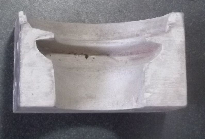
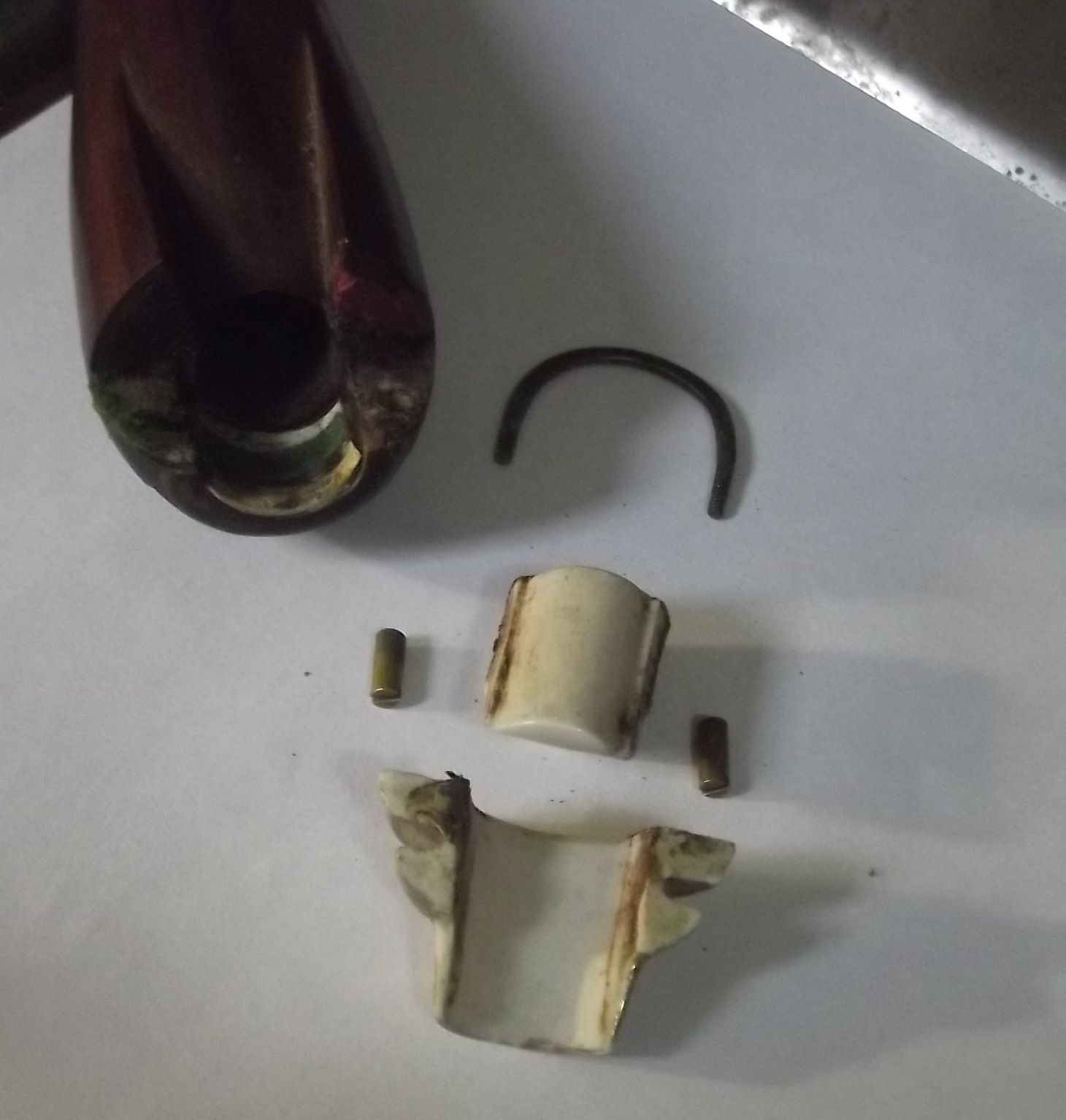
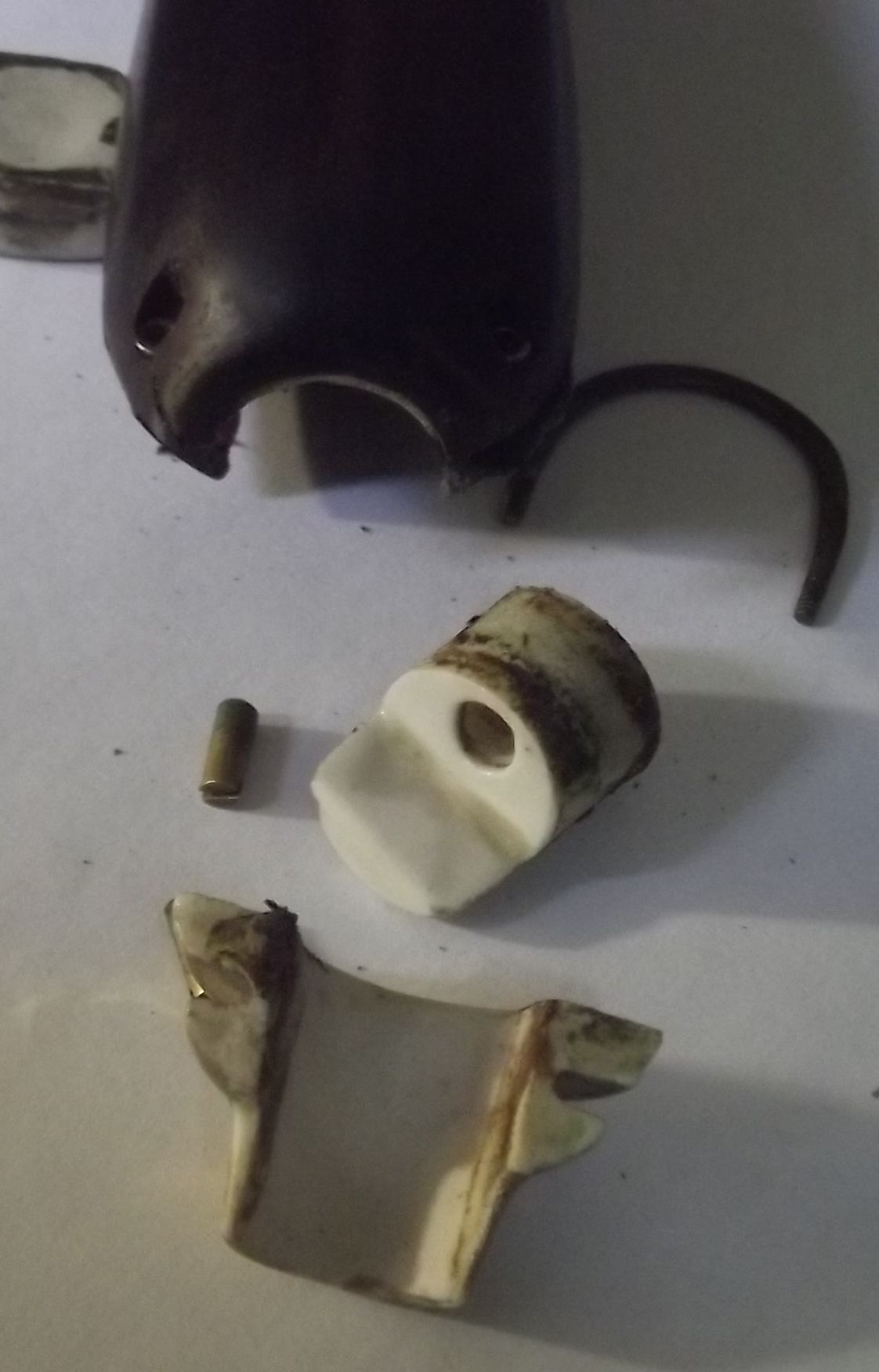
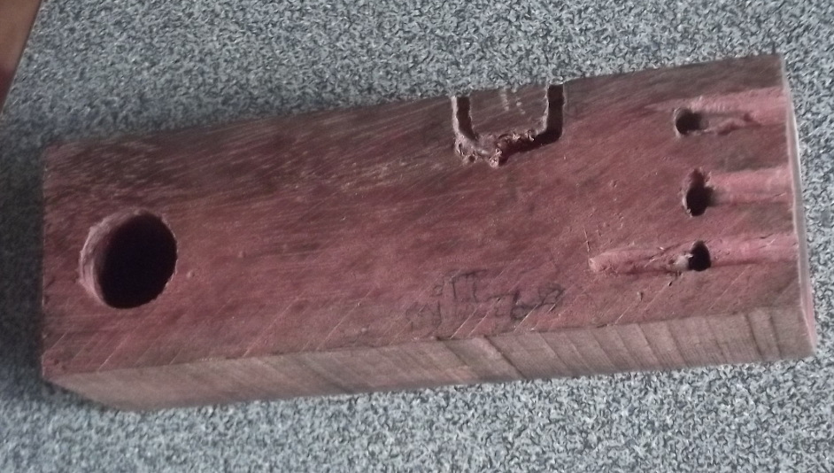
 Here is a mismatched beak and block. The
beak sagged a bit because the sides spread out a bit before or
during firing (probably in pulling it out of the beak mold), and
the center of the windway is too narrow. Yet in my collection is
at least one block that matches this beak. How well that pair
matches the curve of the edge of the labium is another guess,
and the labiums are pretty uniform between instruments. In an
assembled & properly adjusted instrument held up to a light,
one should be able to look along the block and see a thin line
under the labium. It's best if it's uniform all the way across.
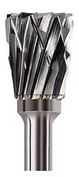
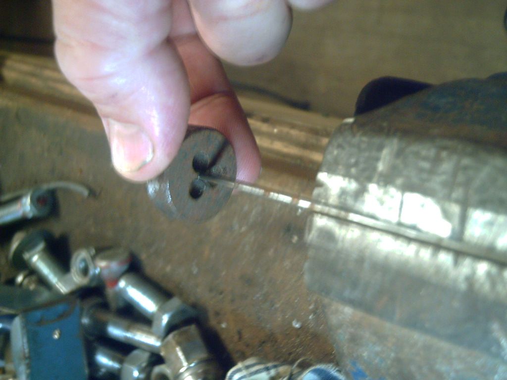
(that's easiest to see with the block in place, beak removed.) As previously mentioned, I used steel
'dremmel mototool' burrs to enlarge tone holes
by undercutting them, reaming them from the inside without
enlarging the outside. (The burr has to fit through the hole.) I
don't remember if I got as refined as this or if it's actually as
useful with burrs as with a knife, but I would think that if the
upper octave is sharper, probably enlarge inside toward the top of
the hole to help raise the lower one more. If the upper octave is
flatter, I would enlarge toward the bottom so as to raise the
pitch of the lower note less. I more remember going around the
whole inner edge, a bit at a time, to raise both pitches.
Here is a mismatched beak and block. The
beak sagged a bit because the sides spread out a bit before or
during firing (probably in pulling it out of the beak mold), and
the center of the windway is too narrow. Yet in my collection is
at least one block that matches this beak. How well that pair
matches the curve of the edge of the labium is another guess,
and the labiums are pretty uniform between instruments. In an
assembled & properly adjusted instrument held up to a light,
one should be able to look along the block and see a thin line
under the labium. It's best if it's uniform all the way across.
(that's easiest to see with the block in place, beak removed.) As previously mentioned, I used steel
'dremmel mototool' burrs to enlarge tone holes
by undercutting them, reaming them from the inside without
enlarging the outside. (The burr has to fit through the hole.) I
don't remember if I got as refined as this or if it's actually as
useful with burrs as with a knife, but I would think that if the
upper octave is sharper, probably enlarge inside toward the top of
the hole to help raise the lower one more. If the upper octave is
flatter, I would enlarge toward the bottom so as to raise the
pitch of the lower note less. I more remember going around the
whole inner edge, a bit at a time, to raise both pitches.