Turquoise Energy News Report #177
Covering
February 2023 (Posted March 5th 2023)
Lawnhill BC Canada - by Craig Carmichael
(CraigXC at Post dot com)
www.TurquoiseEnergy.com
= www.ElectricCaik.com
= www.ElectricHubcap.com
Highlight: ZX40 Mini cargo
Truck; Build & Tests of Magnetic Variable Torque Converter (See
February in Brief, Electric Transport, Video Link - 7 minutes)
Month In "Brief"
(Project Summaries etc.)
- Magnetic Variable Torque Converter: Build + Tests, Video Link -
"New Chemistry" Battery Research & Development - Home Solar Power:
4 Years - Plastic Recycling 2.0 Demo
In
Passing
(Miscellaneous topics, editorial comments & opinionated rants)
- Scattered Thots - ESD
- Detailed
Project Reports
-
Electric
Transport - Electric Hubcap Motor Systems
* Magnetic Variable Torque Converter with Planetary Gear: The
Future of the Automotive Industry! Assembling/Installing one for
Miles Truck: working. - wants still more magnetic interaction
Other "Green"
& Electric Equipment Projects
(no reports)
Electricity Storage:
Batteries
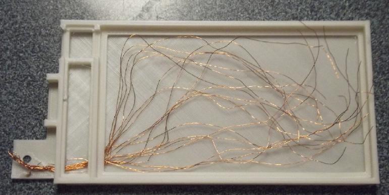
* Gelled Ni-Zn: 3D Printed PVB Case - Copper wire strands for zinc
current collector? - Assembly - Keytone wetting for NiOOH: YAH! -
Testing. Mn-Zn cell: Rechargeable?
Electricity Generation
* My Solar Power System:
- The Usual Latest Daily/Monthly
Solar Production log et cetera - Monthly/Annual Summaries,
Estimates, Notes - FOUR FULL YEARS!
February was again largely a "new chemistry battery R
& D" month, and the results were exciting, not yet "perfect,
working!" but at long last all the pieces seem to be in place to
achieve that on some try very soon.
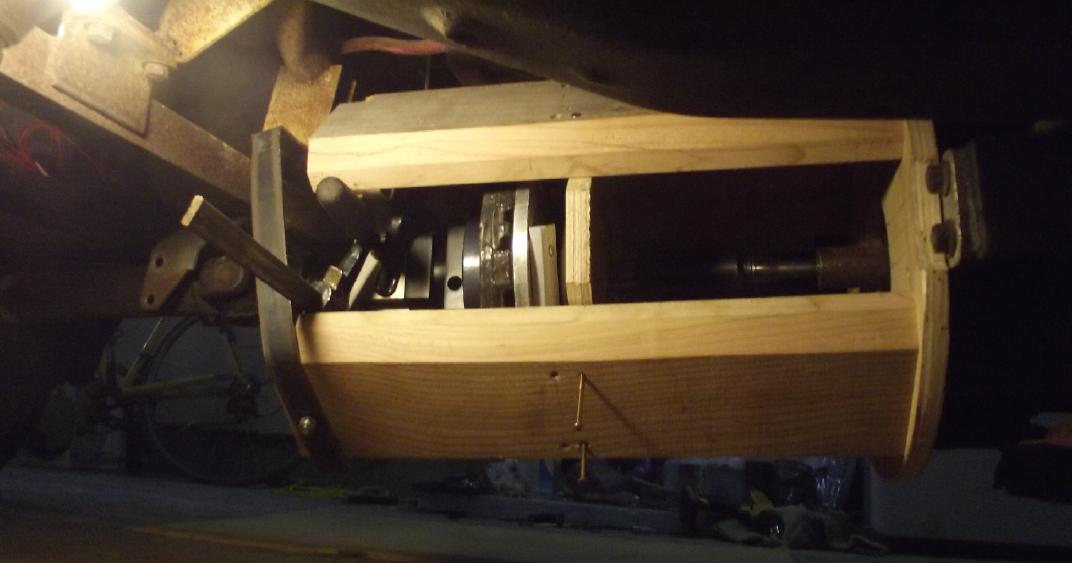
I did finally get the magnetic variable torque
converter in the housing under the truck and working. It ran around the
driveway fine and more than once, but needs still stronger magnetic
rotor interaction. This is achievable and the next step.
I did a sample plate of HDPE plastic molding (Plastic
Recycling 2.0) in the kitchen oven. Some parameters need changing a
bit. 500°F is too hot, 5 or 10 minutes in the oven is too short.
More below.
This month also marks four full years of tracking the
power
from my solar panels. Naysayers say we can't transition to renewable
energy but with all due allowances for difficulties, it is in fact
happening everywhere and if I had around 50 or 60 'sun panes' on my
roofs instead of 18 they would be supplying as much power annually as I
actually use.
Magnetic Variable Torque Converter: Build + Tests, Video Link
Magnetic Torque Converter - February 2023 Tests (Video 7 minutes)
https://youtu.be/MFbFC5YkvTM
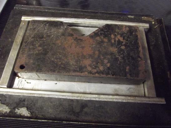
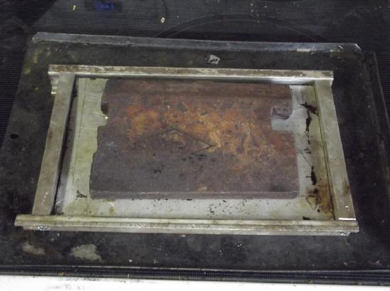
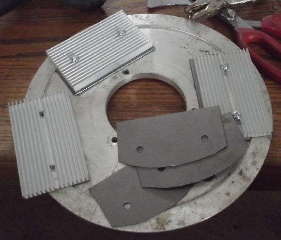
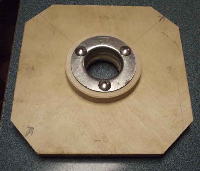 Since the alume disk was getting
too warm, I
changed the bearing
Since the alume disk was getting
too warm, I
changed the bearing
support a little to provide clearance for heatsinks on the disk
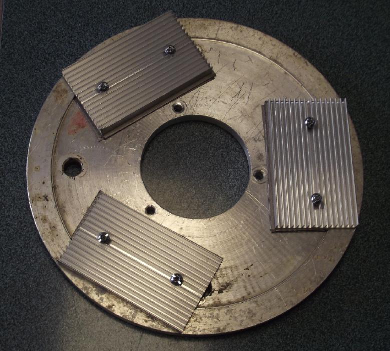 Disk with the heatsinks.
Since the back surface of the disk was uneven I built up the middle
with three layers of graphite foil, which is a very good heat conductor.
In the tests in September the theory for this variable
converter was proven to work,
but what was the optimum level of magnetic interaction? I suspected
what I had
was rather light. I added sideways magnets to the magnet rotor to make
it something of a "Hallbach" configuration with more flux, and with
more of the flux coming out the active side to interact with the alume
disk. Did this double the flux? Probably it was at least 1.5 times
more. I tried it out in the garage after I did it and I could tell it
was better.
Then I realized a planetary gearset with a higher
reduction ratio would magnify the effectiveness of the flux and I
ordered a 10 to 1 to replace the 5 to 1 reduction unit I had. At this
point, the effective magnetic interaction between the two disks became
3 to 4 times as strong as in the initial tests.
Now I've reassembled the unit with the "bare bones" of an
enclosure with a steady bearing on the long shaft, and I drove the
truck around the driveway. In general I was pleased, but in driving
over obstacles, or trying to, I realize that the magnetic interaction
should be still stronger. The alume disk shouldn't be turning backward,
really, at any point even in the slowest driving with the total
design reduction when it is stopped being 10 to 1 (planetary) times 2.2
to 1
(at
the differential) for a total of 22 to 1.
 I tried to drive one
wheel over a 2
by 4 in the garage. It wouldn't go without a run at it at any pedal
press I wanted to apply.
I tried to drive one
wheel over a 2
by 4 in the garage. It wouldn't go without a run at it at any pedal
press I wanted to apply.
It was revving up too much without moving the truck. I was sure it
should go and I put two large carpentry clamps into the mechanism to
hold the body of the planetary from turning. Thus fixed at 22 to 1
reduction, it hopped over the board easily with a light touch on the
pedal.
It demonstrates that still stronger magnetic interaction between the
disks is required.
There is one more way to get more magnetic interaction
before going to larger or multiple rotors. The present 10 inch alume
alloy disk is only about 11mm thick. It was just what I had on hand. If
the thickness was increased to 19 or 20mm (3/4+ inch) it would probably
improve by about 1.5 times. Then, if the disk was pure alume
instead of alloy (from last month's conductivity figures tabled for
heatsink purposes), it would be about 1.42 times better. Multiplying
these, the magnetic effect should be about doubled. So that is my next
step. (Where do I get pure alume? alloy seems much easier to come by.
Pure copper of course would be about 2.4 times better than the present
disk even in the 11mm thickness, but too heavy and costly.)
Further, if
the diameter was increased so the rim was 1/4 or 1/2 inch beyond the
magnets it should catch a little more of their magnetism at the largest
radius for a lesser but noteworthy increase, maybe 10 to 20%.
A significant benefit to increased interaction will be
that the
heat generated into the disk should drop by more than half, since less
slip means less power wasted into it.
So... from "it worked" to [I trust] "it's good" seems to
be: original * 1.5 to 2 (Hallbach) * 2 (increased gear reduction) * 2
(better alume disk) = 6 to 8 times more effective flux - headed for an
order of magnitude. Now I'm almost surprised it worked as well as it
did at first in September.
I also noticed that with steel screws holding the
heatsinks on the rotor, there was a bit of magnetic cogging, where the
screws wanted to align with the magnets. It then occurred to me that if
an amount of steel to make the cogging sufficient but not overpowering
was added to the alume rotor deliberately, when less torque was
required such
as cruising along level road, the disks could magneticly lock together
and the mechanism would all turn as one with essentially 100%
efficiency. 90% is great. 100% is better. And the alume rotor would
cool off. When more torque was required
the cogging force would break free, automaticly unlocking them and
going back to variable conversion.
Onward and upward!
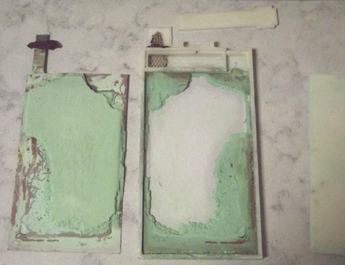
"New Chemistry" Battery Research & Development
 After 4 consecutive months of efforts I think I'm just about there for
making batteries that work and may be practical to use. Almost. (Still
with horribly labor intensive construction.) I've
made 3D printed cases for externally clamped flat cells and epoxied
them shut so they don't leak. Even more labor intensive? At least it
works!
After 4 consecutive months of efforts I think I'm just about there for
making batteries that work and may be practical to use. Almost. (Still
with horribly labor intensive construction.) I've
made 3D printed cases for externally clamped flat cells and epoxied
them shut so they don't leak. Even more labor intensive? At least it
works!
And I've discovered the way to get much better performance
out of positive electrode powders is to soak them in acetone, which (I
believe) helps build more conductive epitaxial crystal structures at
the nano scale. This follows on discovering that soaking separator
papers in toluene prevents the positive electrode nano-powders from
seeping through to short to the negative side, and that painting the
same separator with sodium dodecylbenzenesulfonate seems to keep zinc
ions from penetrating through from the negative side to the plus.
I'm experimenting with a manganese oxide "+" electrode
(among other interesting "+" side chemistries). Manganese is known for
not recharging well from MnOOH back to MnO2 in alkaline cells. I am
seeing if it will recharge at a pH below 14 when also treated with the
acetone. So far it appears to be working, but it's too soon to be sure.
Manganese-zinc is the well known combo of non-rechargeable dry cells.
If it can be made to recharge, it will open the door to cheap, high
capacity batteries potentially to the scale of grid power energy
storage where a whole power grid can charge with solar during the day
and run off the batteries at least into the evening - maybe even until
morning. They'd be more
than fair for electric transport, too, which would make for
substantially lower cost electric vehicles.
But I found where Ovshinsky et al had not only created the
good metal hydride for Ni-MH batteries, but his team had also improved
the nickel oxyhydroxide chemistry to give it higher capacity - even
above the "theoretical" one electron per nickel atom. This makes
nickel-zinc look really attractive for higher energy and still
relatively low cost EV batteries.
Home Solar Power: 4 years
With the improvements I made to the wiring many months ago
including some new plug-in grid ties, two new solar panels on a pole
and three on the carport roof bringing the total to 18 panes, the solar
production for the fourth full year of operation was almost double that
of each of the first three years - about 3800 KWH instead of 2100.
(1.8x) That is about 1/3 as much as my average total annual usage from
BC Hydro, and certainly much more than my electric car uses.
Certainly one loses a lot with too-thin wires from the
panes, also with grid ties loaded up to near their maximum ratings with
panes instead of, say, to half their rating. ...at least that seems to
be true with cheap plug-in grid tie inverters.
Annual totals are at the bottom of this report. Luckily
the weather isn't usually what the pictures show. (March 3rd)
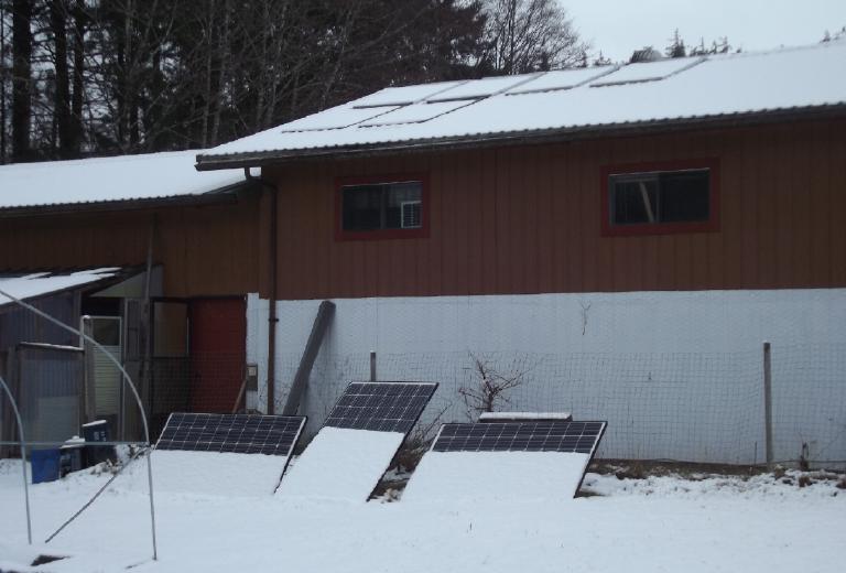 Solar Panels, Four Years
6 on house roof + 3 just propped up on lawn. (What month is
this again?)
(BTW the 10W solar panel in the window is for my bedroom lamp - ~10
years now, same Ni-MH "D" cells)
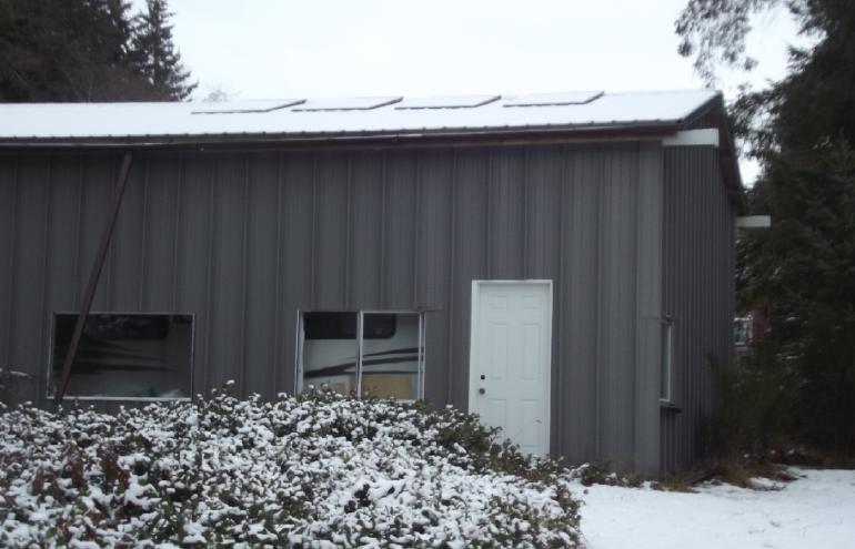 4 on cabin roof
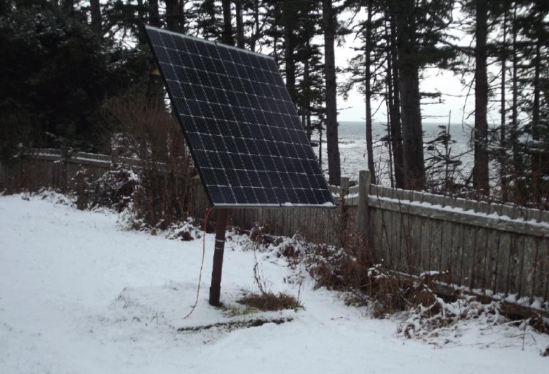 2 on a pole (wired to carport)
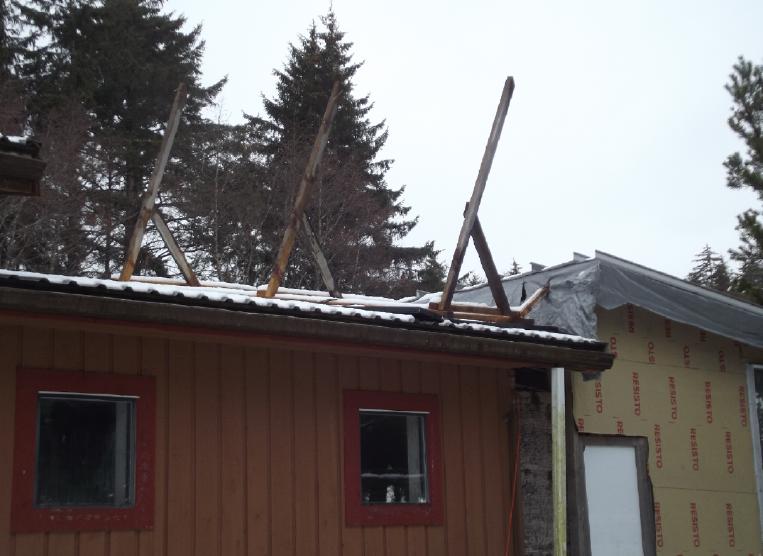 Um, the 3 panels usually facing
south on the
carport roof.
Um, the 3 panels usually facing
south on the
carport roof.
A tremendous wind ripped them out a few days ago and dumped them on the
garage roof.
One is obviously broken (corner of frame is bent). Hopefully the other
two aren't.
I'm waiting for nice weather to go up and put them back -
this time with fat lag screws instead of just deck screws.
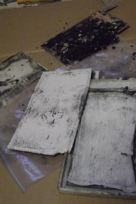
Plastic Recycling 2.0 Demo
 I tried again
to make a little "sample size" HDPE "tile" from a bleach bottle. (I
waited until I was baking and heating up the oven anyway. Not a very
common occurrence!)
I tried again
to make a little "sample size" HDPE "tile" from a bleach bottle. (I
waited until I was baking and heating up the oven anyway. Not a very
common occurrence!)
 I'm not sure what possessed me
to change from the previous 9-1/2 pound weight to a 6 pounder. It
wasn't enough.
I'm not sure what possessed me
to change from the previous 9-1/2 pound weight to a 6 pounder. It
wasn't enough.
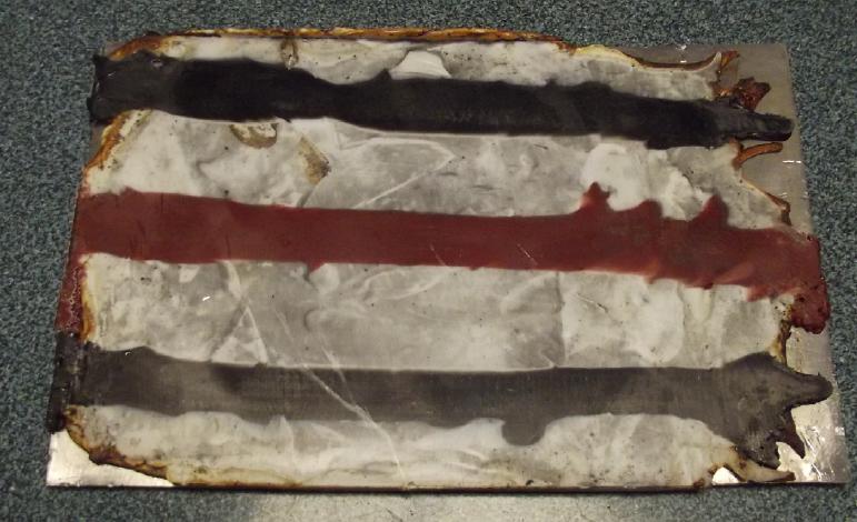 I added some "racing stripes"
from some tear-off strips from 5 gallon HDPE plastic bucket lids. This
time I set the kitchen oven to 500°F but I left the mold in for an
hour instead of just 5 or 10 minutes. The result was that the "tile"
looked scorched around the edges but still hadn't flattened right out
and filled the corners. And it was stuck to the mold quite badly and
hard to separate, especially from the two face pieces without bending
them.
I added some "racing stripes"
from some tear-off strips from 5 gallon HDPE plastic bucket lids. This
time I set the kitchen oven to 500°F but I left the mold in for an
hour instead of just 5 or 10 minutes. The result was that the "tile"
looked scorched around the edges but still hadn't flattened right out
and filled the corners. And it was stuck to the mold quite badly and
hard to separate, especially from the two face pieces without bending
them.
I didn't notice any odor with the HDPE in the oven,
although the window was
open a bit and I didn't sit in the kitchen during the process.
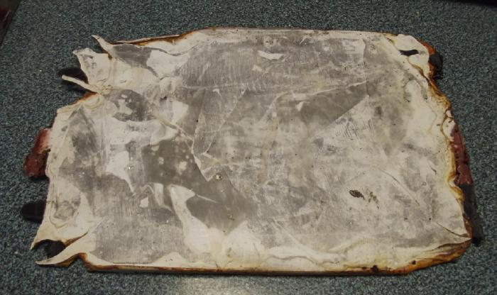 It looks lumpy but these former
pieces of plastic are in fact all melted into a smooth surface top and
bottom. Only the edges are uneven, and scorched. (Too hot, for too
long,
and insufficient weight on top.)
It looks lumpy but these former
pieces of plastic are in fact all melted into a smooth surface top and
bottom. Only the edges are uneven, and scorched. (Too hot, for too
long,
and insufficient weight on top.)
The silver color on the (white bleach bottle) plastic is
polishing compound that was on the mold surfaces. It won't be there
on any subsequent cast.
Conclusions:
1. 500°F (260°C) is too hot for polyethylene. Probably
450°F (232°C) would have been fine; maybe still lower.
2. It does need to be in the oven long enough for all the plastic to
heat up to the desired temperature and to flow. This depends on how
much plastic there is as well as how thick the pieces are and the oven
temperature.
3. 6 pounds of weight on the lid didn't provide enough pressure to
squeeze the melted plastic out to fill the corners, even in this very
small mold. (~14 x 21 cm) (Why did I swap the 9.5 pound weight I used
previously for a 6 pound?)
4. The smaller the cracks around the edges are, the less material needs
to be trimmed off the edges after molding.
5. The higher the sides of the mold, the bigger the chunks of plastic
can be and the less cutting is needed to fit them into the mold. The
low sides of this mold were a nuisance.
6. Spacers in the corners or adjusting screws are useful to make sure
it doesn't come out wedge shaped. (or does for shingles.)
Certainly recycling HDPE plastic into "tiles", sheets or
plates, is pretty simple this way - especially if as it seems, one can
just use the
kitchen oven. One only needs to make a simple box mold. Molds for
making tiles up to about 16 by 21 inches will fit in most electric
ovens. In India and elsewhere they make floor and paving tiles in
similar ways. They'd be great for plastic roof tiles or panels. (They
need testing for flammability before use in or on top of dwellings.
Would they light up from a glowing cinder, or just melt a bit? I'm not
sure what test results may already be available. Consider that cedar
roofing shingles plus a woodstove are a notorious combo for burning
down houses.)
In a town in Argentina I saw they were making houses from
plastic "bricks" and the program was slowed by having a hard time
finding enough waste plastic.
For more ideas, look on youtube.
(I'll try in the kitchen again this month - and with PP.)
In
Passing
(Miscellaneous topics, editorial comments & opinionated rants)
Scattered
Thots
* People once thought lichens were a
type of plant. Then someone discovered they were actually two
organisms: an alga that photosynthesized to provide energy plus a
fungus that can scrounge nutrients out of rocks. The biology world was
indignant, but the discoverer presented indisputable microscopic
evidence. They had to create a new word, "symbiosis".
Recently it has been discovered that that too was
incomplete: most lichens are actually an alga and two different
types of fungi.
>>Lichenologists thought that the fungi in the partnership all
belonged to a group called the ascomycetes. Almost on a whim, Spribille
broadened his search to the entire fungal kingdom, and found that in
almost all the macrolichens - the world's most species-rich group - he
[also] found the genes of basidiomycete fungi.
"There's been over 140 years of microscopy" says Spribille. "The idea
that there's something so fundamental that people have been missing is
stunning."<<
That something so major went undiscovered for 140 years
since the original "symbiotic" discovery only surprises me a little. Of
course it suggests that much has probably been missed in many fields,
contrary to the supposition of many that most broader things must
already be well known. Hence my work looking for valuable things that
have been overlooked in areas of batteries, torque converters, BLDC
axial flux motors and so on, where one would expect that anything
simple and "obvious" would have already been found, probably long ago.
 * It's hard to realize just
how much the mass media indoctrinates us with incereasingly brazen
American oligarchy
propaganda, a narrative being repeated over and over, often as
presuppositions to whatever is being said:
* It's hard to realize just
how much the mass media indoctrinates us with incereasingly brazen
American oligarchy
propaganda, a narrative being repeated over and over, often as
presuppositions to whatever is being said:
"Putin, who invaded Crimea, and who launched an unprovoked invasion of
Ukraine, has now done this..."
They can't just begin with "Russia has now done this..."
In the oft repeated prejudiced preamble, first everything
is blamed on the leader, by constant repetition making him sound like a
villain, as if none of [whatever] would have happened if anyone else
was in charge. ("Turkey, our staunch middle-eastern allay" suddenly
became "Erdigan's corrupt regime" and "Erdigan's tinpot
dictatorship" in news items in the weeks before the attempt to
assassinate him. I became sure they were going to do so. [Huh? He
wasn't elected? The Turkish parliament suddenly has no power?] But they
failed,
and the repetitious damning references to Erdigan suddenly dropped out
of the news.)
Then, we are supposed to forget all about preceding
causative events like the 2014 American sponsored violent coup in
Ukraine that ousted the elected government for a US hand-picked new one
(who conquered Ukraine?), the ongoing eastward expansion of NATO
contrary to solemn promises, the ongoing nazification of Ukraine (as
reported with concern on BBC more than once in 2015 until they were
apparently told to stop) and totally ignoring Russian concerns and
their
warnings reiterated for many years. The fact that Crimea and the
Donbass and 3 or 4 other "Ukrainian" regions were always Russian except
for the period when they were transferred to Ukraine for internal
reasons within the framework of the USSR, and that when given the
chance they voted to be and
are glad to be parts of Russia again, is never mentioned.
...And even having been repeatedly told otherwise, the
highly paid talking heads will say the same things again next week and
next week until most of us simply assume they must be true. And all
the news is blasted out at a machine-gun pace without a pause between
sentences to assimilate what was just said don't think just accept
the words next topic is __! Goebbels would be proud.
And that's just one subject. But I've perhaps said too
much and instigated too much cognitive dissonance in some readers
already!
* Of the seven core human values/motivators, Equality has to be
right at the top. A society can't be sustainable without equality of
opportunity and treatment. Nobel prize winning economist Joseph
Stiglitz gave a
couple of talks available on Youtube about the social costs of
inequality, and how "rent seeking" (extracting someone else's piece of
the pie from them) became the preferred model for "earning" wealth
rather than "wealth creation" (adding to the size of the pie through
production, service).
Joseph Stiglitz: The Price of Inequality - Talk (2012/06/24 - One Hour)
https://www.youtube.com/watch?v=woerUgtufUo&ab_channel=TalksatGoogle
If an hour video seems too long, here's another talk he gave, obviously
less in depth.
The Costs of Inequality: Joseph Stiglitz at TEDxColumbiaSIPA (Talk
2013/03/11 - 16 minutes)
https://www.youtube.com/watch?v=GYHT4zJsCdo&ab_channel=TEDxTalks
* Something not addressed by Stiglitz is overpopulation. Of course
overpopulation results in competition for resources rather than
co-operation, and this competition is a chief contributing cause of
inequality. There is no remedy for this except a smaller population, a
three times larger planet that can sustain 8 billion people over the
generations being unavailable at this time.
The Club of Rome first sounded the alarm in the
later 1960s after running computer projections that indicated that
continued population growth could only be sustained for a few decades
and would end in a huge collapse. In a recent youtube video Neil
McCoy-Ward
shows footage from an actual 1973 Club of Rome report
projecting declining Quality of Life from around 2000 and a
population collapse starting around 2020. Certainly quality lives have
become much harder to come by lately. The greater majority are now
just scraping by.
Neil McCoy-Ward -- with Club of Rome projections 1973 (50th anniversary)
https://www.youtube.com/watch?v=KyrEZAIjRec&t=108s&ab_channel=NeilMcCoy-Ward
Recent crop and herd reductions or failures and problems
all over the food supply chain globally would seem to indicate we are
headed imminently into the drop. In sub-Saharan Africa hundreds of
millions face imminent starvation, and the Africans are no longer being
helped by nations who used to have surpluses but now are headed into
shortages themselves. In the USA every single county now reports there
being food insecurity, and over 50 million people are turning to food
banks for sustenance. Crime is rising rapidly.
Many giving warnings in recent years are surprised how
long our unsatisfactory state of affairs has continued without
collapsing, but the Club of Rome report 50 years ago seemed to have had
the timing pretty well pegged.
ESD
(Eccentric Silliness Department)
* Notice: no, it's not ice
* Woodchuck could chuck wood... Can a complacent communist economist
excel with "Excel" at tax calculations?
* Quarantine: Being forced to stay at home, read the Quoran and drink
tea.
* The closed caption said Germany was supplying Ukraine with "Leper
tanks". NOW I know why Ukraine is losing!
* And Britain is sending "Sea Cucumber", er, I mean, "Sea King"
helicopters. In Canada these are notorious for falling out of the sky
into the ocean.
* What's this coffee bag at the back of the top shelf? How long has it
been up there?
Egads, is that the expiry date?
"in depth reports" for
each project are below. I hope they may be useful to anyone who wants
to get into a similar project, to glean ideas for how something
might be done, as well as things that might have been tried, or just
thought
of and not tried... and even of how not to do something - why
it didn't
work or proved impractical. Sometimes they set out inventive thoughts
almost as they occur - and are the actual organization and elaboration
in writing of those thoughts. They are thus partly a diary and are not
extensively proof-read for literary perfection, consistency,
completeness and elimination of duplications before
publication. I hope they may add to the body of wisdom for other
researchers and developers to help them find more productive paths and
avoid potential pitfalls and dead ends.
Electric
Transport
Magnetic Variable Torque Converter with Planetary Gear
[22nd] Some kind of
lethargy took over... and battery stuff. Anyway I
cut a piece of plywood to extend the bearing holder out 4/5 of an inch
so I could put three 10mm tall heatsinks on the alume disk. Later I
finally went under the truck and dismantled the whole assembly. Prime
candidate for what was slipping: it looked like the SDS hub wasn't
closing tightly enough on the shaft, which may be a bit undersize. I'll
run a zip disk through the
slot to make it wider and be sure it can close enough.
[23rd] yikes! Now that it's dismounted
and apart and I'm ready to make all the
changes, it's blowing a storm and -5° out there. Not conducive to
working in the unheated shop, and I don't suppose even 3000 watts of
portable heaters would make it anything like warm. Dang, I think I'll
sit by the woodstove instead.
[26th] I've done bits and pieces here and there (while confessing to be
presently much more interested in batteries). It has warmed above
zero... and then gotten
colder and snowed. Most of the detail items on my list are done.
 [27th] I finished the list
items and put the heatsinks on the alume disk. The surface wasn't flat,
and I propped them up with 3 layers of graphite "foil", having
discovered that solid graphite is probably a better heatsink material
than alume itself. (or even than copper?)
[27th] I finished the list
items and put the heatsinks on the alume disk. The surface wasn't flat,
and I propped them up with 3 layers of graphite "foil", having
discovered that solid graphite is probably a better heatsink material
than alume itself. (or even than copper?)
Then I reassembled the housing, and the rotating
mechanism. (My back already hurts. I'm I really going to start crawling
under the truck to install it again? Maybe tomorrow!)
Torque Converter 100% Efficiency on the Road?
I had worked out efficiencies once under way to be in the
90%
range. That seemed acceptable as it is apparently better than
"automatic transmissions" even tho they have been much improved during
this century. But an interesting "feature" presented itself. With even
the small steel screws holding the heatsinks there was a noticeable
amount of magnetic cogging between the two disks. It occurred to me
that provided the motor is easily able to overcome that cogging, when
torque requirements are small the alume disk can magneticly "stick" to
the magnet disk and the entire mechanism will turn at 1 to 1 with 100%
efficiency. Perfect! So to get this when torque requirements are lower
- perhaps as when cruising on level pavement - a certain amount of
magnetic steel might well be added to the alume rotor to get it all to
synchronize - automaticly - when conditions favor it.
Potential drawbacks: 1. The pedal will have to be pressed
far enough to overcome the cogging to start moving from a stop. Then
the vehicle may "lurch" into motion. 2. There may be some vibration
when the converter isn't running at 1 to 1. How serious these potential
objections would be needs to be determined. There may be a reasonable
amount of steel to make them trivial yet still get the 100% in most
cruising. It's something for future "fine tuning" experimentation.
[28th] Heating garage up to 13° so I can work in it. It clicked
"on" the instant I moved it up from 5°.
Weight: housing (before epoxy) 13 pounds. Rotating
mechanism: 23 pounds. Heavy enough to lift... but I should be thankful
I can handle them separately, and I don't need a chain hoist, jack or
something!
The housing went on okay, but the mechanism wouldn't push
into the splined socket on the motor, which had always gone easily
before. The shaft didn't quite line up. It seemed the housing had
become slightly trapezoid. I took out some screws to loosen things up,
and worked it in, but it still wasn't straight. Good enough for the
test, but to avoid premature wear I'll want to address that before I
epoxy up the housing. Then one of the heatsinks was nicking one of the
2 by 6'es as it went by. Rather than do it all over again I let it
click. Again the trouble was probably the trapezoid.
When at length I had a camera on underneath and drove out
of the garage... it worked! I went quite slowly and the result was
"catching" on every little lump or root in the grass and when going
upslope, having to press pretty hard on the pedal to get moving again.
But move it did. Pushing through the snow required some extra torque
too. The alume disk still got pretty hot - I got just a whiff of the
heat from in the cab.
I had only a video of the mechanism, and somehow the
camera was aimed too far forward and didn't show the rear driveshaft.
Having no cameraman I set another camera on a tripod. I made another
circle of the driveway and got the footage of both the mechanism and
the moving truck. I drove a little faster this time and it went quite
smoothly. I didn't smell heat from the disk. It was probably pretty
warm, but even at a still pretty low speed I didn't have to press the
pedal so far, so it probably wasn't as hot. And doubtless the spinning
heatsinks made a difference. But as I think about it, there isn't any
good place for the air to enter near the center to be thrown to the
outside by the heatsinks for good air circulation. I can drill a few
holes in the bearing holder plywood. (Start of new list!) I still like
the idea of venting the disk to the windshield to help defog, but it
would be a considerable job.
In my rough driveway, I estimate that even with the 10 to
1 reduction planetary, the hallbach rotor magnet configuration and the
disks almost touching each other, the magnetic coupling was barely
adequate; by no means excessive.
Things that could help increase it would be a thicker
(than ~11mm) alume rotor, using pure alume instead of alloy, and making
a more optimized hallbach magnet rotor. (Pure copper is still better,
but it's heavy and costly. Again, conductivity ratios: Alume alloy 167
/ Pure alume 237 / Pure copper 401. Pure alume 237/167= 1.42 times
better than alloy. 401/237= 1.69 times better than pure alume, or
401/167= 2.40 times better than alume alloy. A 3/4 inch thick pure
alume disk would probably be about twice as good as the alloy one I
used.) Beyond that, it would have to be larger diameter rotors, or even
multiple rotors. (The Chevy Sprint with the already-bought 7 to 1
planetary straight to the wheel is likely to want 12 inch rotors, the
best I can make or get.)
Later I took a third trip around the driveway for no
special reason. I also tried to drive over a 2 by 4 behind one wheel on
the level garage floor. Using a fair amount of pedal, it wouldn't go
from a stop, without a run at it. Just like with the 5 to 1 planetary
in my original concept tests, except this 2 by 4 had all square corners
and so was a bit more challenging. For sure still more magnetism would
be helpful. This sort of a torque converter was surely entirely
impractical before the creation of powerful rare earth magnets.
Magnetic Torque Converter - February 2023 Tests (Video 7 minutes)
https://youtu.be/MFbFC5YkvTM
[March 1st] I thought that with the 10 to 1 planetary reduction times
the 2.2 to 1 rear differential reduction, 22 to 1 should easily drive
over a 2 by 4. I put in a couple of carpentry clamps to keep the body
of the planetary from turning. Sure enough, the truck hopped over the 2
by 4 in both directions with a slight touch of the power pedal. (The
disadvantage to such a fixed ratio being, of course, that the motor
would be
over-revving even at a quite low speeds. With the variable torque
converter it
wouldn't run too fast even at 200 KmPH on the highway. ...BTW, I don't
think I would dare run this truck at over about 60.)
Conclusion: The magnetic coupling surely isn't as strong
as would be desirable. When the ground is dry I'll have to try it on
hills. But it should be good enough to drive around, and my next step
is to epoxy up the housing and make it really solid, and fill in the
open walls so as to keep road dirt out.
But to finish I think I want that 3/4 inch thick pure
alume disk, which should be around double the magnetic coupling of the
present ~11mm alume alloy disk. That should be at least close enough to
an "ideal" strength of magnetic coupling. And, the magnetism doesn't
stop right at the edges of the magnets. I'm sure making the alume rotor
at least 1/4 inch, or better 1/2 inch or more larger radius than the
magnet rotor, would be just that much better. (Egads, that would make
it an 11+ inch rotor instead of 10 inches! I'd have to expand the
housing.)
(And while I'm at it, another 12 inch diameter disk for
the
Sprint. With a 12 inch magnet rotor, that should be around 2.6 times
more torque than this one... which without the truck's 2.2 to 1
differential reduction means only about a 1.18 times torque improvement
to the wheel. But the Sprint is lighter. Or again maybe a 13+ inch size
to catch more outer edge magnetism. Hmm... can I actually fit this in
under the hood?)
Other "Green" & Electric Equipment Projects
No Reports
Electricity
Storage
New Chemistry Batteries
Here we are on the fourth
consectuvie month of battery R & D, and I think I'm awfully close
to making cells that actually perform well. A couple of vital new
things were learned, and a 3D printed case designed.
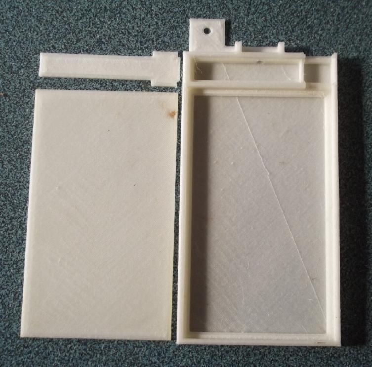
3D Printed Battery Cases
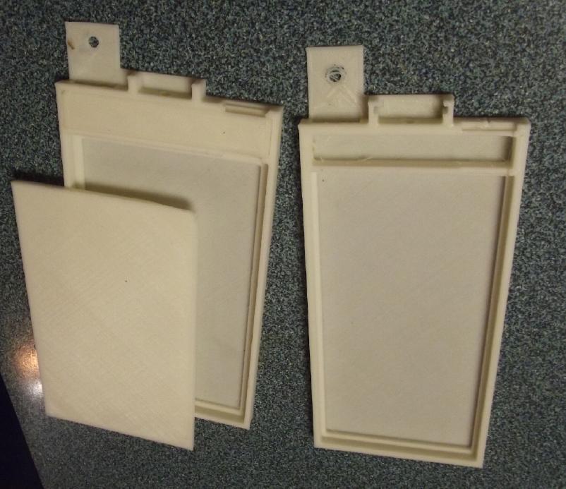 [13th] I went through my
old 3D printed battery case designs and found
one from 2013. Solid plastic might be heavier than packaging tape, but
other than that it (unsurprisingly) seemed to have most of the things I
wanted: in
particular a divider to keep electrolyte materials away from the edges
of the separator papers and a small reservoir at the top for liquid.
Why wouldn't I just use that design?
[13th] I went through my
old 3D printed battery case designs and found
one from 2013. Solid plastic might be heavier than packaging tape, but
other than that it (unsurprisingly) seemed to have most of the things I
wanted: in
particular a divider to keep electrolyte materials away from the edges
of the separator papers and a small reservoir at the top for liquid.
Why wouldn't I just use that design?
I doubled the height of the cell (making it like the ones
I've been making lately) and tweaked various other dimensions, then
printed a sample one in PLA plastic. Just a model to inspect: PLA will
disintegrate from the alkaline electrolyte and it is aggravating that
the "new"
printer won't print ABS properly. However, I should think PVB will work
okay. I printed the back (the bottom on the printer bed) in just three
.3mm layers and discovered that I could put my mouth up to it and force
air through it. But it was half the weight of the ones made from
purchased ABS
sheets and much better adapted to the job. I will likely wrap them up
in packaging tape to keep them from leaking anyway. (Doesn't work.)
As one new innovation I may put in a thin frame after the
separator papers are put in, to keep the upper electrode away from
their edges during assembly as well as the lower one.
Then, and more importantly, I will make a front piece with
ridges (or a thick, lightweight "hollow" piece) that fits just
inside the rim. It can be pushed into the box to compact the
electrodes as much as is useful, the ridges or thickness making it
stick out from the box and against the alume clamp regardless of exact
thicknesses of the materials within. This seems like a much better plan
than anything I've come up with before. Again wrapping in packaging
tape may be the simple way to prevent leaks.
[14th] The next day I tweaked a few
things and then had a hard time
with the 3D printer - again. (It worked so well yesterday!) I looked on
line. Hairspray was recommended as a possible fix to get things to
adhere better. Or glue stick. Of course you don't want the plastic
adhering so well that it's hard to get off, so it's a tradeoff. The
heated glass bed is great if it sticks, because the part just comes
right off once the bed is cool. But the parts lift too easily during
printing. Clean glass (rub with acetone) and warm, dry filament are
vital. I might try printing ABS with the hairspray idea. (...worked
well with the PVB.)
The entire complex shaped case less the main front cover weighed
31.35g, but the front cover, 3mm thick, weighed 31.6g and actually took
longer to print! That makes the whole case 63 grams. That front cover
just can't be good for energy by weight! (Hmm, I forgot about the idea
of printing a thinner sheet with ridges - maybe to look like a heatsink
with fins?)
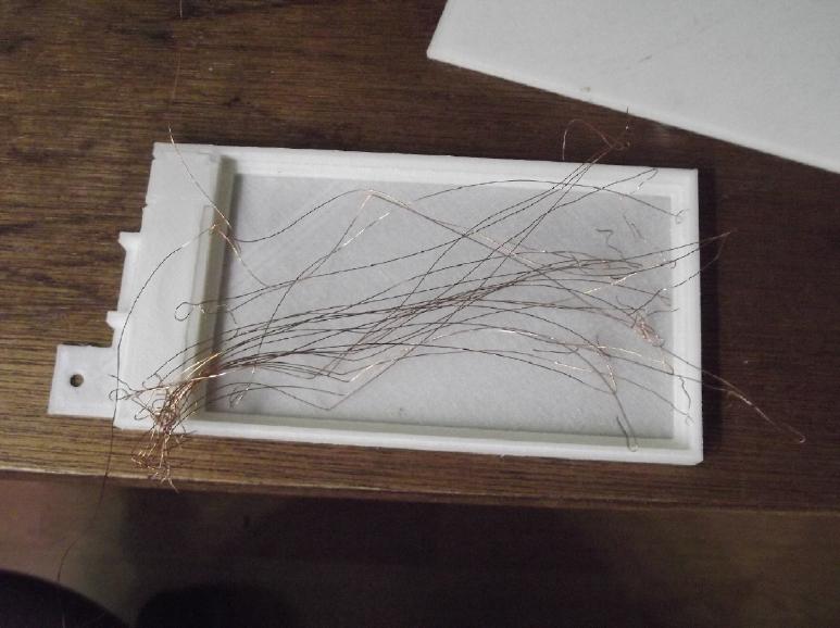
Copper Wire Strands Current Collector?
 I had also
been thinking that expanded copper mesh for a
zinc current collector was nice, but not very common or cheap. But what
about
fine stranded wire? I cut open a short length of a #6(?) wire from "cab
tire"(?). It came apart into 7 bundles of fine stranded wires.
I had also
been thinking that expanded copper mesh for a
zinc current collector was nice, but not very common or cheap. But what
about
fine stranded wire? I cut open a short length of a #6(?) wire from "cab
tire"(?). It came apart into 7 bundles of fine stranded wires.
 I took
one bundle, about 7 inches long, and combed it out. It was just 2
grams. (The copper mesh was 4-5g.) A bit of a mess, but if one had a
system, it could be well spread out without big gaps. And the zinc
itself would plate onto the copper in charging and do a lot of filling
in.
I took
one bundle, about 7 inches long, and combed it out. It was just 2
grams. (The copper mesh was 4-5g.) A bit of a mess, but if one had a
system, it could be well spread out without big gaps. And the zinc
itself would plate onto the copper in charging and do a lot of filling
in.
 [16th] I bought some hairspray and some glue
stick. (They still sell
glue stick!?!)
[16th] I bought some hairspray and some glue
stick. (They still sell
glue stick!?!)
I didn't see anything I didn't like in the second model. I
changed the upper cap a bit to cover two gaps at the upper electrode
terminal strip. I printed that and adjusted a dimension slightly so it
fit better.
I cleaned and sprayed some hair spray onto the printer
bed, then I printed a "for real" cell case with the rather costly PVB
(poly vinyl butyrate) filament. None of it lifted off the bed during
printing - Yay!
I decided to go for the main cover just 2.1mm (7 layers of
plastic) thick. If it goes all the way in I'd have to add some extra
posode material.
[17th] For the copper wires current
collector idea I had been thinking of
drilling holes in a piece of plastic for small nails in a pattern to
string the wires across and cover the whole electrode with even
distance between wires. That sounded tedious... wait a minute! I can 3D
print a piece of PLA complete with the holes!
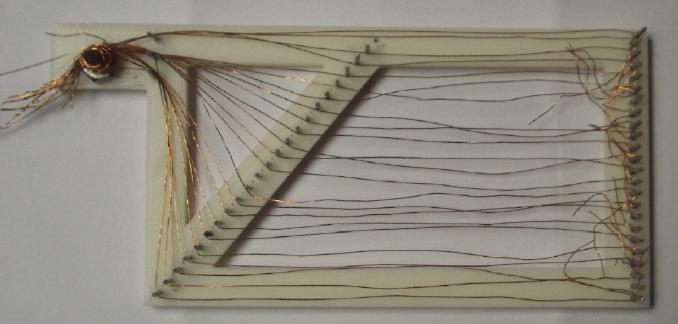 [18,19th] I printed the
"pin toad". I had envisioned the wires stung
across taut like on a harp. It didn't really work out that way. and I
didn't
get
them interlocked at the bottom. And it took too long. (It would have
been easier and doubtless neater with one long strand instead of a
bunch of short ones.)
[18,19th] I printed the
"pin toad". I had envisioned the wires stung
across taut like on a harp. It didn't really work out that way. and I
didn't
get
them interlocked at the bottom. And it took too long. (It would have
been easier and doubtless neater with one long strand instead of a
bunch of short ones.)
 When I took it off, it was just a mess.
I suppose one could weave some strands across, making it a loose
"window screen" weave. Or wrap long strands around the
zinc sheet, although that would leave half on the wrong side of the
sheet to make indents into the separator paper. Perhaps best to use
the extruded mesh until I run out, and meanwhile hope for an
inspiration.
When I took it off, it was just a mess.
I suppose one could weave some strands across, making it a loose
"window screen" weave. Or wrap long strands around the
zinc sheet, although that would leave half on the wrong side of the
sheet to make indents into the separator paper. Perhaps best to use
the extruded mesh until I run out, and meanwhile hope for an
inspiration.
I used the mesh and put a
zinc electrode into the 3D
printed case. Then I prepared separator papers and put them in place.
Keytones! (Epitaxial crystalline growths?)
[20th] I wetted my nickel hydroxide mix [TE News #176] with
methyl
ethyl keytone and put about 30 grams into the cell. Then I cut a
cupro-nickel current collector, painted the active face with calcium
oxide, and set it on top. I closed the top and wrapped the whole cell
with packaging tape, then put it in the clamps. The clamps seemed to
press the front fully down to the sides, and it was only charging at
30mA. (But it didn't leak - yay!) I took it out, slit the tape, pulled
the top off, and added another 10 grams of Ni(OH)2 mix. (Now around 3.6
amp-hours) This time it definitely didn't press right down. In fact, it
had "too much" material at the bottom and I had to get a couple of
longer screws. Then the re-wrapped cell leaked, badly. So I took it out
again and wrapped another layer of tape on. Then it only leaked a tiny
bit, and I left it. Shining a flashlight through it from behind and
tilting it, I could see there was only a bubble of air in the top
reservoir. But I should have made the filler hole bigger - to see in
and
also so a pH paper strip would fit in - so I adjusted the 3D print
design for next time.
The cell started off with somewhat higher charging
currents than usual - maybe double, but not that order of magnitude
I've been after. 55, 60 then down to 45mA after an hour. With 4
amp-hours of Ni(OH)2 to charge it was still going to take 4 days to
charge. When I put a load on, the voltage would drop down to some
level, but it didn't continue dropping and dropping from there the way
all my previous cells have done ever since I started experimenting and
had learned enough to get battery-like results. In fact, it even seemed
to rise up 10-20mV after 20 or 30 seconds under load. What an
improvement! It could hardly be anything but the ketone - that was
really the only thing different. Like wetting the separator paper in
toluene (or varsol), wetting the positive electrode with a keytone was
unintuitive but vital. It certainly took too many years to figure it
out! (No doubt there are many other workable processes to do similar
things, and I'll just take the first ones I've found, but one must
realize that some process for something seems to be required in the
first place. Perhaps these things aren't required in pH 14 alkaline
solution, and since everyone doing rechargeable aqueous cells until now
has gone with pH14 KOH, that explains why such aren't mentioned in the
literature - not that I've found, anyway. Separators are much
discussed, but it didn't seem related to electrode powder leakage.)
It still leaked a bit. In a few hours there was no water
in the reservoir and the currents were dropping - probably drying out.
(Initial charging was proably using water, too.) I slit the tape and
took it apart, down to removing the top current collector. The nickel
electrode was about 3 to 4mm thick. I'll remark that that's a pretty
thick electrode, to match only a thin slice of zinc - the reason to
find some other positive elctrode element(s). I didn't see that any had
been converted from turquoise Ni(OH)2 into black NiOOH yet, although
there was probably a little, perhaps hidden under the surface.
 About half the
electrode substance stuck to the
cupro-nickel current collector and half stayed in the box. I had been
looking them up and thought methyl-methyl ketone (AKA acetone) should
be better than methyl-ethyl keytone, and I availed myself of this
fortuitous opportunity to let it all dry out and wet the outside
portion stuck on the current collector with acetone, with no chance of
it affecting the separators or the other electrode. When I put it back
together there should be enough difference to notice any significant
further performance improvement.
About half the
electrode substance stuck to the
cupro-nickel current collector and half stayed in the box. I had been
looking them up and thought methyl-methyl ketone (AKA acetone) should
be better than methyl-ethyl keytone, and I availed myself of this
fortuitous opportunity to let it all dry out and wet the outside
portion stuck on the current collector with acetone, with no chance of
it affecting the separators or the other electrode. When I put it back
together there should be enough difference to notice any significant
further performance improvement.
[21st] I put the electrode back. It went nicely back into place without
any of the powder crumbling or falling off and jamming things up. I
taped it up, put it back in the clamps, and filled it. It started
charging at only about 45mA - again 4 days to charge all that NiOOH.
[22nd] Performance seemed to be up which
was great news, but my plan for
sealing the cells simply by wrapping them in packaging tape seems to be
a failure. They often seem okay at first but leak worse and worse as
the
hours pass. Supposedly PVB can be solved with alcohol, and it should be
easy enough to seal up the top reservoir area. As for sealing the main
front cover, my confidence level is low, and even the thin back wall
could be slightly porous and electrolyte seep out.
Maybe what I need to do is "pot" them - dip the whole cell
in some kind of epoxy or something? Hmm... one might perhaps epoxy them
into sets, like 12 volts worth, going thick on the ends for rigidity,
and
forget the alume clamps?
[23rd] Having at long last found this ketone/acetone method of getting
more out of nickel oxyhydroxide, it occurred to me to look up the
subject on line. Sure enough, more info! The article (May 2020) said it
was standard practice "in the scientific literature" to heat the nickel
hydroxide to 300°C. That converted some of the hydroxide to oxide.
Hmpf! In all I've read none of it bothered to mention this small but
apparently vital preparation detail. Perhaps that's why my electrodes
have always had such poor conductivity and performance. (What if I just
started with nickel oxide?)
But the article spoke of heating the hydroxide to 900°
for an hour instead. It was said that in theory that would break it
down and ruin it. They tried it anyway and found that the electrode
made from it generated 50% more electricity than usual even after 6000
cycles! Their focus was about using the nickel hydroxide electrode as a
cheaper catalyst (than platimum or paladium) to hydrolize oxygen out of
water, but they also tried it as a battery positive electrode.
That should mean that instead of 90 amp-hours per
kilogram, it would yield about 135. The theoretical limit of 289 AH/Kg
is still a ways off. How about if I heat some up - maybe just to over
300° (about 500°?) for a first try - and after it cooled wet it
with acetone? Could it do even better? After all these years, suddenly
I find two performance improving techniques in two days!
Fortuitously I've just bought a controlled temperature
electric furnace for melting metals! It goes up to 1100°. The
larger crucible should hold quite a lot of the powder. (Since I haven't
potted the cell yet, I think if it comes out easily I'll take out the
Ni(OH)2 and heat treat it (complete w. the monel & samarium oxide
powders), then acetone again. Then I'll treat a new batch of just
Ni(OH)2 powder.)
This time most of the electrode stuck to the metal current
collector. It didn't stick to the separator sheet, so it all came out
easily. There was just a bit of black (presumably NiOOH) right on the
current collector. Not much charged! I put it in at 500° for 25
minutes, then ground
it back to powder and re-did the electrode. Most of the powder had
converted into black nickel oxide, and there was only 27 grams instead
of near 40. (Why am I starting with nickel hydroxide instead of just
nickel oxide from the pottery supply shop, again?) Let's see:
Ni-OH-OH (59+17+17=93) => NiO (59+16) (59+16=75) + H2O (18) boiled
off, or .8 times as much weight. "Should" have been over 30 grams left,
but it might not really have been 40 to start with, and I lost a little
on the way.
 Tub of black nickel oxide. A bit
of the source
material, turquoise
Tub of black nickel oxide. A bit
of the source
material, turquoise
nickel hydroxide, is seen around the edges of the cell above it.
If it gets 150 AH/Kg, that's 4.05 amp-hours instead of
3.6, and with less material. (One can always dream!) A little acetone,
grind it with mortar & pestle. (it became fine powder again almost
at once - black powder.)
The rest of the jar of NiOHOH: 78 grams. Put it in crucible, in metal
melting oven @ 500°C for 25'. It "boiled over", strewing powder all
around the lid area. (Yuk!)
 I mixed a little epoxy
(25g) and smeared it all over the cell except the top, and with a
couple of pieces of sheet polyethylene to keep the epoxy from the
alume, screwed it into the clamps. I set it by the woodstove to set and
put the remainder of the cup in the freezer to keep for a day or two in
case it needed touching up.
I mixed a little epoxy
(25g) and smeared it all over the cell except the top, and with a
couple of pieces of sheet polyethylene to keep the epoxy from the
alume, screwed it into the clamps. I set it by the woodstove to set and
put the remainder of the cup in the freezer to keep for a day or two in
case it needed touching up.
On line again, I found a
patent by Stan Ovshinsky & crew (company "Ovonics".) Ovshinsky not
only
created the thin film transistor (TFT) that gives us our flat screen
monitors & TV's, but the nickel-metal hydride flooded batteries of
GM's EV-1 fame, that first made electric cars sporty, long range and
long lasting in the late 1990s. Some of these batteries lasted 20+
years. I knew he had formulated the metal
hydride that made these batteries possible, but I didn't know they had
made important improvements to the nickel oxides side as well. Combos
of 3+ elements mixed by special techniques to give more than
one electron valence change per nickel atom... ooh! This is going to
take some reading to get the gist of!
From Ovonics Patent: (Think GM EV-1 battery):
Nickel hydroxide positive electrode material exhibiting
improved conductivity and engineered activation energy
[0051] This discrepancy between theoretical capacity and the capacity
achieved by the prior art can be explained by
the fact that nickel hydroxide has an enormous number of available
sites for hydrogen storage, but that many or most
of those sites cannot be effectively utilized. This is because:
* the NiO-H bond is outside the thermodynamic window accessible for use
in a sealed, alkaline electrolyte cell;
* the competing O 2 evolution reaction;
* poor conductivity where highly charged nickel oxihydroxide material
cannot be fully discharged or is at least severely
* rate dependent, or pockets of charged material may exist even after
discharge due to such poor conductivity;
* the inaccessibility of those sites because the surface of the
particles does not allow electrolyte penetration, and the
* unoptimized crystallite size make the conductivity and "active
surface area" of the crystallites insufficient.
[0060] The benefit of using dopants in addition to, and as a substitute
for cobalt,� cannot be over emphasized. Cobalt
is very expense relative to the other battery materials, and therefore,
significantly influences final NiMH battery cost.
Cobalt also is uniquely capable of being almost completely substituted
for Ni and soluble within the nickel hydroxide
host matrix. The instant inventors believe that nickel hydroxide
materials modified only with cobalt have a tendency to
be single phase. Because these materials avoid becoming "multiphase",
and disordered, they cannot provide the following
desirable properties:
* formation of a spectrum of NiO to H binding energies
* formation of small crystallites (improving accessibility)
* increased conductivity
* multiple electron transfer per Ni atom resistant to swelling and
operable over a wide range of temperatures
* engineering local and intermediate range order
[0061] The instant inventors have found that combinations of elements
(such as Ni-Co-Zn-Mg-Ca or
Ni-Co-Zn-Mg-Ca-Mn-Cu) show synergistic behavior relative to the
expected electrochemical effects
from just the individual elements alone.
Anyway, this cell is sealed in epoxy. How or whether it
works is in limbo, and I don't think I'll be taking apart to make any
changes, but it's less likely to leak than any previous cell!
I filled it to the brim with weak KCl solution (thinking
there's probably enough CuCl2 in it already and some KCl) but of course
it took time for it to penetrate into the zinc electrode and then
across the separator sheet, so I filled it several times until it
stayed full.
It didn't seem to leak. But the charge jumped right up to
the supply voltage and it only started charging at 10mA. In an hour it
didn't go higher. It would go up a little for a bit if I drew some
current off it, but was soon back to 10mA. It seemed really
disappointing. Had heating the nickel hydroxide to oxide wrecked it
instead of improving it? Did I do it too hot or for too long? There was
nothing to do but leave it overnight and see how it was in the morning.
I suspect another cause of low currents is painting the
separator sheet with osmium dopant instead of painting it directly on
the zinc.
With zinc granules and powder it seemed like it would use way too much,
but
now I'm putting in actual zinc sheet again, and I should coat that
instead. (Too late for this cell, now epoxied shut!) The zircon can be
put in with the zinc powder, and the 'extra' parchment separator sheet
can be done away with.
[24th] In the morning the cell charge was up to 17mA. The voltage
wasn't staying up yet and quickly dropped under 1.5V - not too
surprising since it was taking so little charge. I tried a 60 Ω load.
It was less than impressive except for one thing: again, unlike all my
previous cells, the voltage didn't quickly start fading. It fell from
1.4xx to 1.038V when I put the load on, but after 20 minutes it had
risen to 1.110V instead of falling off. After 25 minutes it was still
1.109V. When I removed the load it rose in 1/2 a minute to 1.309V, and
1.314V by one minute. When I put it back on charge it started out
drawing 90mA and only gradually worked its way back down while making
up for the load energy, being still 34mA after 10 minutes. A few
minutes later a 10 Ω load started at .600V and rose considerably in a
minute to .651V. Then 1 Ω started at .100V and rose to .126V, then
dropped to .125V at the 1 minute mark. Again charging started at over
90mA.
I can only hope the cell continues to improve bit by bit for quite some
time. In mid afternoon, then late afternoon, performance was creeping
up marginally but perceptibly.
Manganese Dioxide?
The remarkable change in the performance of the nickel
oxides from wetting the powder with acetone got me thinking about MnO2
again. MnOOH or Mn2O3 (valence 3) is known to not recharge (to MnO2,
valence 4)... but that's in pH14 alkaline solution. What would happen
in salt solution at a lower pH, and if it was treated with acetone? A
friend said he had once tried recharging an ordinary salt dry cell (pH
6?) and it had recovered 70% of its charge. Surely at least some of the
MnOOH or Mn2O3 had to recharge to MnO2 to do that? (He said on the
second recharge, it leaked. Probably the zinc can was weakened and
there would be pressure inside during charging.)
A perpetually rechargeable manganese zinc cell would be
very low cost (in principle) and very high energy by weight: dynamite!
(It could even be made by recycling old dry cell materials.) I decided
it was worth trying. If it worked it would be, at least, the obvious
choice for power grid level stationary energy storage. And it would be
a cheap EV battery too, and quite lightweight even if not "the
ultimate".
Having thought of it, in spite of the many things I should
be doing, I just had to try it. I had another 3D printed battery case.
I had some MnO2 from dry cells. One more expanded copper mesh grill.
One more cupro-nickel sheet cut. And some varsoled watercolor paper
separators. I had the epoxy in the freezer, which would soon harden if
not used...
I put the copper mesh (4.25g) in the case, and a zinc
sheet (13.6g) on that. I painted the osmium dopant straight onto the
zinc. Then I mixed some zinc powder with a bit of zircon
(3.0g+13.6g=16.6g Zn) and spread it around on top. Then I painted a
separator paper with SDBS.
[25th] I took the dry cell MnO2+graphite and added a little Sm2O3 to
raise the oxygen overvoltage. I put in lots of acetone and mixed. I
filled the cell to the brim with this. I painted the current collector
with CaO (=> Ca(OH)2) and put it on top.
Then I got the epoxy and made a horrible mess. I turned
the cell over to do the back first and the front came off and spilled
powder. I did finally put it together, with epoxy and powder all over
the counter. I got some polyethylene sheets into the clamp and screwed
everything down. I set it near the woodstove to set and managed to
clean up the counter with many paper towels and a fair bit of acetone.
My black fingers (in spite of one plastic glove and "I can keep the
other hand away from the epoxy" -- ha ha) were another story. Next...
mid afternoon! Time to get on with my day.
 When I unclamped it to look, it was still a mess. An area of the
back had powder all over it and the case was sunken in. The remaining
acetone in the MnO2 evidently had melted the back. Still, it didn't
look hopeless and after I scraped the powder away I filled the cell. It
didn't seem to leak. (fyew!)
When I unclamped it to look, it was still a mess. An area of the
back had powder all over it and the case was sunken in. The remaining
acetone in the MnO2 evidently had melted the back. Still, it didn't
look hopeless and after I scraped the powder away I filled the cell. It
didn't seem to leak. (fyew!)
Then I clamped
both cells -- first time there've been two cells in the clamp!
It read 1.05V right off the bat. Let's see, MnO2-Zn at pH
11 is about +.35 - -1.15 = 1.5 volts. About the same as at any pH. I
set the power supply to 1.60V
and charged through 0.1 Ω. I must have got more things right this time,
because the charging current started way over 100mA - maybe 200. It
soon dropped to 110-125mA... and stayed there! There, at least, was
something with an order of magnitude improvement, at least, over 10 or
20mA.
A few hours later it seemed to not be performing well, but
it was leaking after all. (Sigh!) I figured it was that messy back
area, but the leak was actually around the edge of the front face. I
left it overnight by the woodstove for the cracks to dry out before
smearing some more epoxy on it here and there, and put the Ni-Zn cell
back on charge.
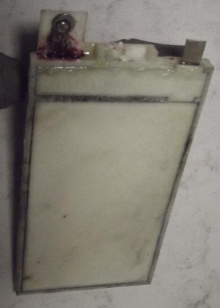
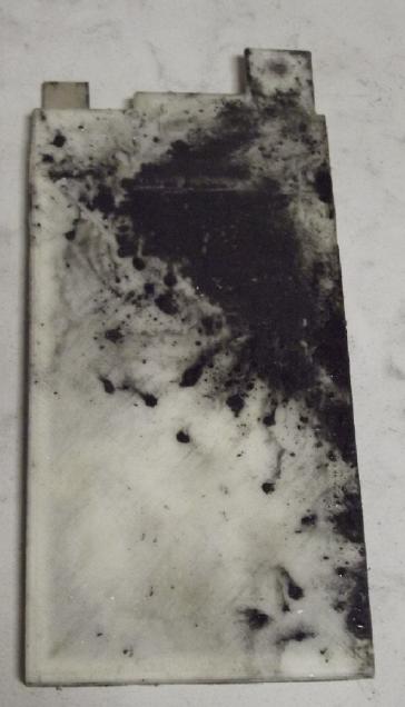
Black powder
seeped through
the poorly "toluened" separator
 [26th] The Ni-Zn cell,
however, right from the start hadn't seemed to hold charge. I was
hoping it was just the slow charging, but right from the start, the
more it was charged, the faster it discharged until it was down around
1.3 volts. This time it had actually reached 2 volts where it should
have sat happily, but the charging current was up instead of down, and
as soon as the charge was disconnected it began its relentless and
rapid drop in voltage. I guess somewhere in the compacting the
separator sheet must have ripped at the edge or something. Being sealed
with epoxy I can't take it apart. At least not without totally
destroying it. I suppose it's worth sawing open if I can figure out
what's wrong. Or I could just assume I know what's wrong, and just
lower the lip inside (another millimeter?) so the bottom zinc electrode
area is thinner and the separator doesn't touch the lip until it's
being squeezed in by the upper electrode.
[26th] The Ni-Zn cell,
however, right from the start hadn't seemed to hold charge. I was
hoping it was just the slow charging, but right from the start, the
more it was charged, the faster it discharged until it was down around
1.3 volts. This time it had actually reached 2 volts where it should
have sat happily, but the charging current was up instead of down, and
as soon as the charge was disconnected it began its relentless and
rapid drop in voltage. I guess somewhere in the compacting the
separator sheet must have ripped at the edge or something. Being sealed
with epoxy I can't take it apart. At least not without totally
destroying it. I suppose it's worth sawing open if I can figure out
what's wrong. Or I could just assume I know what's wrong, and just
lower the lip inside (another millimeter?) so the bottom zinc electrode
area is thinner and the separator doesn't touch the lip until it's
being squeezed in by the upper electrode.
I got the last of the epoxy out of the freezer and touched
up the Mn-Zn cell. In the -25°C freezer it still wasn't hardening
much yet after 3 days.
But the Mn-Zn cell is doing the same thing as the Ni-Zn
one, but with higher currents. I supposed it was because the zinc
material doesn't fill the whole cavity, so when the powder is put in
and compacted, it pushes into the voids at the edges and rips the
separator. Nope! I chiseled the Ni-Zn cell apart at the seams and
didn't see any signs of ripping except what I caused opening it. What I
saw instead was a bit of black on the wrong side of the separator
sheet. Some of the nickel oxides nano powder had seeped through it,
creating a short.
I knew I wanted toluene (methyl benzene) and not varsol!
(Maybe the Co-op Home Centre or Home Hardware would order me some
toluene if I asked? Looking it up on line, I found that naphtha was
mainly xylene (dimethyl benzene) and trimethyl benzene. Maybe naphtha
camp stove fuel is the best thing I can get right now? That, and
treating the paper more than once. I had two treated sheets left and I
doused them with varsol again. Then I found some Coleman camp stove
fuel. 3rd time lucky? I doused them with it. But "Naphtha" is an
ambiguous term of various formulas. The methyl benzene ones are
"solvent naptha". But Coleman camp fuel is evidently "petroleum
naphtha" which is quite different. But none of them guarantee specific
chemicals or in specific percentages. Hmm... Varsol is largely "solvent
naphtha", ie, di- and tri-methyl benzene.
[27th] I looked on line and found toluene in 1 liter cans at Home
Hardware. I phoned Home Hardware in Masset. They had it! Apparently I
had somehow neglected to phone the one place of three on this island
that might - and did - have it when I was looking for it 2 or 3 months
ago. I bought it over the phone and called Port Air Cargo to deliver it
to me. (Sigh, 40$ instead of 20$. But it's too far for the Leaf and
there's a brake sticking on my Toyota Echo that needs fixing before I
try going anywhere in it again. That's likely to cost much more than
the toluene! Repair will have to wait until it stops snowing and is
warmer.) It came Wednesday, March 1st and I doused the two separator
sheets once more, this time in the desired stuff! Between that and 4
dousings, hopefully I can start making battery cells that actually work
properly and last a long time!
[28th] I 3D printed two new cell cases. The second one was because
somewhere the devious software had switched itself to "print support
structures" and it filled in the lower slots and the filler hole - ug!
Why would it do such a thing on a printer it knew had just one extruder
and no soluble filament? It had been printing the slots just fine with
almost no sag. (to my initial surprise) I could drill the hole out, but
it would be difficult to cut the two thin slots where they need to go
without wrecking the whole print.
To be continued...
My
Solar
Power
System
I think maybe I like "photo panes" as a (somewhat) short
form for "solar panels", or "panes" for "panels".
The Usual Daily/Monthly/Yearly Log of Solar
Power Generated [and grid power consumed]
(All times are in PST: clock 48 minutes ahead of local sun time, not
PDT which
is an hour and 48 minutes ahead. (DC) battery system power output
readings are reset to zero
daily (often just for LED lights, occasionally used with other loads:
Chevy Sprint electric car, inverters in power outages or other 36V
loads), while the
grid tied readings are cumulative.)
Daily Figures
Notes: House Main
meter (6 digits) accumulates. DC meter now
accumulates until [before] it loses precision (9.999 WH => 0010
KWH), then is
reset. House East and Cabin meters (4
digits) are reset to 0 when they get near 99.99 (which goes to "100.0")
- owing to loss of second decimal precision.
Km = Nissan Leaf electric car drove distance, then car was charged.
New Order of Daily Solar Readings (Beginning May 2022):
Date House, House, House, Cabin => Total KWH Solar [Notable
power
Uses; Grid power meter@time] Sky/weather
Main
DC East Cabin
January
31st 4233.39, 7.05, 7.71, 1.79 => 5.78
[4666@17:30]
February
1st 4234.63, 7.19, 8.50, 2.38 => 2.76 [55Km;
4713@17:30]
2d 4236.10, 7.29, 9.46, 3.10 => 3.25
[4751@18:00]
3rd 4236.96, 7.38, 9.85, 3.45 => 1.69 [90Km;
4797@17:30]
4th 4238.16, 7.45, 10.56, 4.04 => 2.57 [50Km; 4840@17:30]
5th 4239.53, 7.56, 11.33, 4.60 => 2.81 [4880@17:30]
6th 4241.88, 7.65, 13.13, 5.89 => 5.53 [60Km; 4919@18:00]
7th 4244.94, 7.75, 15.03, 7.57 => 6.74 [4952@18:00]
8th 4245.74, 7.82, 15.37, 7.87 => 1.51 [60Km; 4995@18:00]
9th 4247.36, 7.93, 16.75, 8.80 => 4.04 [5029@18:00]
10th 4249.96, 8.06, 18.90, 10.11 => 6.19 [90Km; 5071@17:30]
11th 4251.09, 8.09, 19.49, 10.60 => 2.28 [50Km; 5112@18:00]
12th 4253.22, 8.15, 21.28, 11.95 => 5.33 [5146@17:30]
13th 4257.76, 8.23, 24.74, 14.57=>10.70 [5174@18:30]
14th 4260.40, 8.34, 27.21, 16.15 => 6.80 [5211@17:30] SNOW!?!
15th 4261.01, 8.46, 27.59, 16.49 => 1.65 [60Km; 5255@17:30]
16th 4264.66, 8.55, 29.60, 18.29 => 7.55 [35Km; 5294@18:30]
17th 4266.49, 8.66, 30.67, 19.18 => 3.90 [5339@20:00]
18th 4268.18, 8.77, 31.64, 19.95 => 3.54 [55Km; 5371@18:00]
19th 4269.15, 8.87, 32.17, 20.38 => 2.03 [5404@18:30]
20th 4272.59, 8.97, 35.00, 22.46 => 8.45 [5422@18:30]
21st 4275.27, 9.05, 37.42, 24.00 => 6.71 [5454@18:00]
22d 4279.99, 9.23, 41.07, 26.92=>11.47 [60Km; 5480@18:00]
MINUS -2° and gusty winds? (probably -5° last night?)
23d 4282.27, 9.31, 41.95, 27.94 => 5.26 [5542@18:30] -5°
Today, powerful wind gusts blew over carport solar panels.
24th 4284.16, 9.42, 42.30, 28.80 => 3.21 [5586@18:00] -0°, snow.
Fixed roof, didn't get sunpanes back up. One is bent, must be broken.
25th 4286.92, 9.50, 43.00, 30.33 => 5.07 [55Km; 5631@18:00]
26th 4288.24, 9.59, 43.84, 31.06 => 2.98 [5667@18:00]
27th 4288.94, 9.67, 44.59, 31.45 => 1.92 [5706@18:00] Snow covering
most of the panes.
28th 4292.58, 9.75, 45.81, 34.26 => 7.75 [5745@18:30] Snow melted
off panels.
March
1st 4294.21, 9.86, 46.09, 35.00 => 2.76 [5781@18:00] Snow melting in
rain. Didn't get carport panels fixed yet.
2d 4296.29, 10.0, 46.94, 36.48 => 4.55 [50Km; 5817@18:30] More
snow! Some sun too.
3rd 4296.92, 0.09, 47.32, 36.84 => 1.46 [85Km; 5861@19:00] Still
snow on panels.
4th 4303.26, 0.21, 48.70, 41.14 =>12.14 [30Km; 5895@19:00] Snow
musta melted.
5th 4310.38, 0.30, 50.05, 46.08 =>14.40 [5921@19:00]
Chart of daily KWH from solar panels.
(Compare FEBRUARY 2023
(left) with January 2023 & with February 2022 - but note number of
solar
panels differs from last year.)
Days of
__ KWH
|
February 2023
(18 solars)
|
January 2023
(18 solar panels)
|
February 2022
(15 s. panels - 2
mostly in shade)
|
0.xx
|
|
5
|
2
|
1.xx
|
4
|
8
|
4
|
2.xx
|
6
|
7
|
8
|
3.xx
|
4
|
2
|
3
|
4.xx
|
1
|
3
|
2
|
5.xx
|
4
|
2
|
5
|
6.xx
|
4
|
|
3
|
7.xx
|
2
|
2
|
1
|
8.xx
|
1
|
2
|
|
9.xx
|
|
|
|
10.xx
|
1
|
|
|
11.xx
|
1
|
|
|
12.xx
|
|
|
|
13.xx
|
|
|
|
14.xx
|
|
|
|
15.xx
|
|
|
|
Total KWH
for month
|
132.46
|
93.79 |
102.14
|
Km Driven
on Electricity
|
713.1 Km (odo 92583)
(110KWH?)
|
811.9 Km
(~130 KWH?) |
893.8
(~130 KWH?)
|
Things Noted - February 2023
* Nothing much
Monthly Summaries: Solar Generated KWH [& Power used from
grid KWH]
Month: House system (+ DC system at house) + Cabin system = KWH made
[used from grid]
2019
March 1-31: 116.19 + ------ + 105.93 = 222.12 KWH - solar [786 KWH
used from
grid] (10 solar panels
total)
April - 1-30: 136.87 + ------ + 121.97 = 258.84 KWH [608 KWH]
May - 1-31: 156.23 + ------ + 147.47 = 303.70 KWH [543 KWH] (11th
solar panel connected on lawn on 26th)
June - 1-30: 146.63 + 15.65 + 115.26 = 277.54 KWH [374 KWH] (36V, 250W
Hot Water Heater installed on 7th)
July - 1-31: 134.06 + 19.06 + 120.86 = 273.98 KWH [342 KWH]
August 1-31:127.47 + 11.44+91.82+(8/10)*96.29 = 307.76 KWH [334 KWH]
(12th solar panel connected
on lawn Aug.
1)
Sept.- 1-30: 110.72 + 15.30 + 84.91 = 210.93 KWH [408 KWH]
(solar includes 2/10 of 96.29)
Oct. - 1-31: 55.67 + 13.03 + 51.82 = 120.52 KWH solar
[635 KWH used from grid]
Nov. - 1-30: 36.51 + 6.31 + 26.29 = 69.11
KWH solar [653 KWH used from grid]
Dec. - 1-23: 18.98 + .84* + 11.70 =
31.52
KWH, solar + wind [711 KWH + 414 (while away) = 1125 from grid]
2020
Jan. - 6-31: 17.52 + ------* + 10.61 = 28.13 KWH,
solar+ wind [1111 KWH from grid]
Feb. - 1-29: 56.83 + ------* + 35.17 = 92.00 KWH,
solar + wind [963 KWH from grid]
* The solar DC system was running the kitchen hot water
tank. Now it's only running a couple of
lights - not (usually) worth reporting. So there's just the 2 grid tie
systems:
house and "roof over travel trailer" (AKA "Cabin").
One year of solar!
March - 1-31: 111.31 + 87.05 = 198.37 KWH solar total
[934 KWH from grid]
April - 1-30: 156.09 + 115.12 = 271.21 [784 KWH
from grid]
May - 1-31: 181.97 + 131.21 = 313.18 KWH
Solar [723 KWH from grid]
June - 1-30: 164.04 + 119.81 = 283.82 KWH Solar [455 KWH
from grid]
July - 1-31: 190.13 + 110.05 = 300.18 KWH Solar [340
KWH from grid]
August- 1-31: 121.81 + 83.62 = 205.43 KWH Solar [385KWH
from Grid]
Sept. - 1-30: 110.68 + 65.09 = 175.77 KWH Solar [564
KWH used from grid]
Oct. - 1-31: 67.28 + 42.55 = 109.83
KWH Solar [1360 KWH from grid -- Renters!]
Nov. - 1-30: 35.70 + 20.79 = 56.49
KWH of Solar [1301 KWH from grid]
Dec. - 1-31: 19.78 + 11.31 = 31.09
KWH Solar [1078 KWH used from grid]
2021
Jan: 25.47 +
18.58 = 44.05
KWH Solar [1185 KWH used from grid] (1
solar panel moved to DC system only -- 11 panels)
Feb: 47.18 + 33.22 = 80.40
KWH Solar [1121 KWH used from grid]
Two years of solar!
Mar: 81.73 + 55.22 + 2.2 (DC) = 139.15 KWH
Solar
[1039 KWH grid]
April: 161.83 + 112.35 + .44(DC) = 274.62 KWH
Solar
[680 KWH from grid]
May: 156.25 + 97.22 + 1.29(DC) = 254.76
KWH
Solar [678 KWH from grid]
June: 197.84 + 112.07 + 2.21(DC) = 312.12 KWH Solar
[& 448 KWH from grid]
(Connected
12th solar panel -- 13 panels total but one goes to DC system
only.)
July: 204.35 + 121.21 + 4.06(DC) = 329.62 KWH
Solar [426 KWH from grid; 150(?) KWH used by Nissan Leaf]
Aug: 176.19 + 102.91 + 5.37(DC) = 284.47 KWH Solar [477 KWH
from grid; 165 KWH (est) used by car]
Sept: 94.35 + 51.34 + 3.30(DC) =
152.29 KWH Solar [590 KWH from grid; 155 KWH (est) used by car]
Oct: 77.52 + 41.85 +
4.10(DC) = 123.47 KWH Solar [1066 KWH from grid; 150 KWH (est) used by
car] (2 new panels on pole
making 14 --
but they are mostly in shadows all winter.)
Nov: 34.69 + 18.92 + 3.82 = 57.43
KWH Solar [1474 KWH from grid (ouch!); 140 (est) used by car]
Dec: 24.00 + 5.22 + 3.76 = 32.98 [1589 KWH from grid (ouch
again! Must be the -10°'s); 120 KWH used by car] (New switches allow switching
some panels
between AC and DC as needed, so all 15 are productively employed.)
2022
Jan: 32.83 + 20.54 + 4.57 =
57.94 KWH Solar [2556 from
grid] Double ouch! Trailer 400W heater, Perry's RV 500W heater, bedroom
heat, car using extra power (100 KWH with less driving)... and so
little
sun!
Feb: 66.63 + 32.09 + 3.42(DC) = 102.14 KWH Solar [1118
KWH from grid; 130 (est) used by car]
Three years of solar!
March:128.53 + 82.29 + 3.66(DC) = 214.48 [1124 KWH from grid;
160 KWH (est) used by car]
April: 251.29 + 149.87 + 3.01(DC) = 404.17 KWH Solar
[911
KWH; est. 170 KWH used by car]
May: 255.01(house)+6.46(DC)+140.46(carport)+145.91(cabin)=547.74
KWH Solar [933 KWH from grid;
140 KWH (est) used by car; Bitcoin miner using extra power from 22nd
on.] (3 new solar panels
on carport roof
-- sunniest location around -- total 18)
Jun: 234.54 + 2.10 + 160.70 + 139.18 = 536.52 KWH
[from grid: 864 KWH - dang bitcoin miner!]
July: 232.12 + 4.57 + 143.03 + 139.65 = 519.37
KWH Solar [from power grid: 710 KWH; 165 KWH (est) used by car]
Aug: 205.57 + 4.20 + 157.88 + 137.47 = 505.32 KWH Solar [from
grid: 561 KWH; 145 KWH (est) used by car]
Sept:165.52 + 3.97 + 132.24 + 104.29 = 406.02 KWH Solar [from
grid: 856 KWH; car used (est): 165 KWH]
Oct: 97.96 + 2.86 + 78.76 + 59.04 = 238.62 KWH
Solar [from grid: 1067 KWH; car used (est): 143 KWH]
Nov: 47.37 + 3.30 + 37.81 + 26.43 = 114.91 KWH solar.
[from grid: 1504 KWH; car used (est): 120 KWH]
Dec: 31.05 + 3.11 + 29.46 + 16.35 = 79.97 KWH Solar. [from grid:
1266
KWH; car used (est): 135 KWH]
2023 - (House roof, lawn + DC + Cabin + Carport, Pole) Solar
Jan KWH: 40.57 + 3.06 + 28.31 + 21.85 = 93.79 Solar [grid: 1163; car
(est): 130]
Feb KWH: 59.19 + 2.70 + 38.10 + 32.47 = 132.46 Solar [grid: 1079; car:
110]
Four years of solar!
Annual Totals
1. March 2019-Feb. 2020: 2196.15 KWH Solar [used 7927 KWH
from grid]
2. March 2020-Feb. 2021: 2069.82 KWH Solar [used 11294 KWH from grid]
(More electric heat - BR, Trailer & Perry's RV)
3. March 2021-Feb. 2022: 2063.05 KWH Solar [used 10977 KWH from grid]
4a. March 2022-August 2022: in (the best) 6 months, about 2725 KWH
solar - more than in any previous entire year!
4. March2022-Feb. 2023: 3793.37 KWH Solar [used 12038 KWH from grid]
Money Saved or Earned - @ 12¢ [All BC residential elec.
rate] ; @
50¢ [2018 cost of diesel fuel to BC Hydro] ; @ 1$ per KWH [actual
total
cost to BC Hydro
in 2022 according to an employee]:
1. 263.42$ ; 1097.58$ ; 2196.15$
2. 248.38$ ; 1034.91$ ; 2069.82$
3. 247.57$ ; 1031.53$ ; 2063.05$
4. 455.204 ; 1896.69$ ; 3793.37$
It can be seen that the benefit to the society as a whole
on Haida Gwaii from solar power installations is much greater than the
cost savings to the individual user of electricity, thanks to the heavy
subsidization of our power
owing to the BC government policy of having the same power rate across
the entire province regardless of the cost of production. And it can be
insurance: With some
extra equipment and a battery, sufficient solar can deliver essential
power in
electrical outages however long. (Feb 28th 2023: And it's probably well
over 1$/KWH by now the way inflation of diesel fuel and other costs is
running.)
https://www.TurquoiseEnergy.com
Haida Gwaii, BC Canada