Turquoise Energy News Report #185
Covering
October
2023 (Posted November 3rd 2023)
Lawnhill BC Canada - by Craig Carmichael
[CraigXC at Post dot com]
www.TurquoiseEnergy.com
= www.ElectricCaik.com
= www.ElectricHubcap.com
Month In "Brief"
(Project Summaries etc.)
- Miles Mini Cargo Van EV - T-Plugs & T-Sockets (12V, 36V DC
Wiring): Double Plugs - Cabin Construction - Hydro Dams Versus River
Flow Hydro
In
Passing
(Miscellaneous topics, editorial comments & opinionated rants)
- Israelstine - Scattered
Thots () - ESD
- Detailed
Project Reports
-
Electric
Transport - Electric Hubcap Motor Systems
* Miles Truck - for now: Fixed
ratio Drive
* The Long-Planned Unipolar "Electric Hubcap" Motor
- New Idea: Hallbach Stator Configuration? ...as well as
Hallbach Rotor - HUGE magnetic flux, torque!
Other "Green"
& Electric Equipment Projects
* T-Plugs & T-Sockets (36V DC Wiring)
* Cabin Construction
* Handheld Bandsaw Mill - some notes
* October's Gardening
Electricity Storage:
Batteries [no reports]
Electricity Generation
* My Solar Power System: - The Usual Latest Daily/Monthly
Solar Production log et cetera - Monthly/Annual Summaries,
Estimates, Notes
October in Brief

Five adults and six almost adult chicks are eating a lot. I've started
letting
them out to forage not long before dark - hopefully after the hawks and
eagles
have retired for the evening but before the raccoons come out. It's
worked so far.
They're weeding the gardens. (In spring I'll have to beef up the garden
fences.)
(They go back into the coop as it gets dark, and I lock the door
against raccoons.)
People say I have much the best tasting eggs. Giving them good food
& greens must pay.
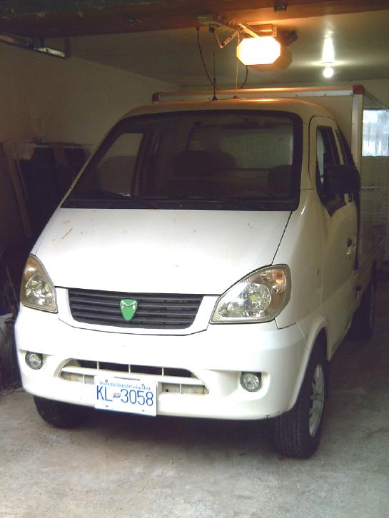
Miles Mini Cargo Van EV
Being (to my surprise) unable to get a pure alume or a
decent copper rotor for the magnetic variable torque converter, I
finally decided to put the fixed 5 to 1 reduction planetary gear back
in for the time being. Now it has the wooden housing with (if nothing
else) a steady bearing on the shaft to keep things in line. Luckily I
found in my metal scraps the original pieces of steel to hold the
planetary in place.
[14th] I assembled the transmission assembly under the truck again and
put in the
two pieces of steel for holding the planetary gear body, and marked
where to weld them together. The angle iron piece had been bent to
sharper than a right angle, but I managed to right it with a large vise
and two 15 inch crescent wrenches - one wrench on the end of the other
to make a longer handle.
I ground 1/4 of the way around the hex head on four bolts,
almost down to the shaft, so they would fit in the narrow corners of
the planetary gear. This saved me from looking for non-existent socket
head bolts, and since they couldn't turn it actually made assembly
easier.
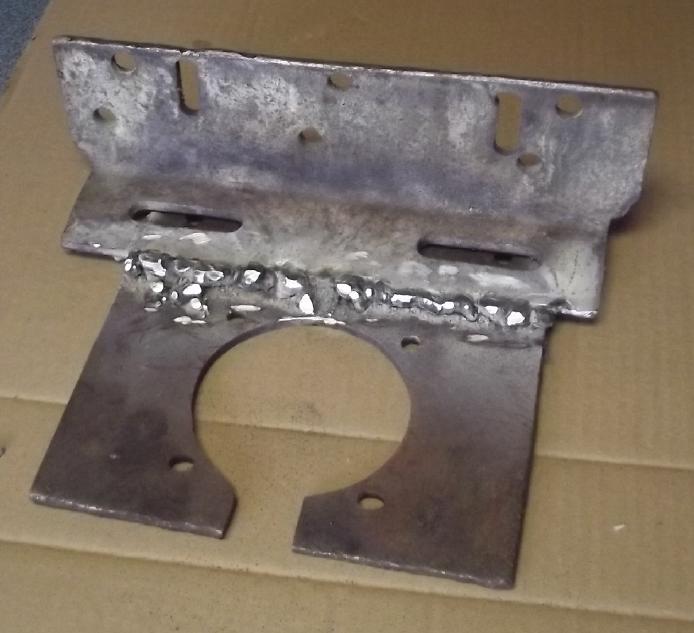
 [22nd] I
welded the two pieces together, having brought the MIG welder into the
house from the cold shipping container (storage) a few days previously
to be sure it was dry. My welding still looks like crap, but I put a
lot of metal onto this.
[22nd] I
welded the two pieces together, having brought the MIG welder into the
house from the cold shipping container (storage) a few days previously
to be sure it was dry. My welding still looks like crap, but I put a
lot of metal onto this.
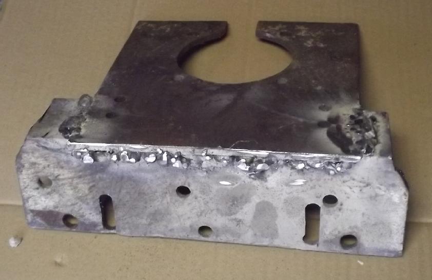
The plate
holding the
planetary gear with 4 bolts, bolted above (hidden) to the frame
brackets.
 On the late
evening of the 30th after working on the cabin most of the day as
usual, I finally installed the transmission with the fixed 5 to 1
planetary gear in the truck.
On the late
evening of the 30th after working on the cabin most of the day as
usual, I finally installed the transmission with the fixed 5 to 1
planetary gear in the truck.
Now, it seems like
really primitive technology to lock the planetary gear body in place,
compared to having the driving forces smoothly balance magneticly and
to have the reduction ratio smoothly drop to near 1 to 1 as vehicle
speed
increases!!!
It ran fine in the garage. It hopped eagerly over a 2 inch
board.
Next morning I ran it around a bit on the circle driveway.
It sounded a bit "rough". That's probably because the planetary body is
bolted
direct to the frame with no rubber padding. (I hope the shaft parts are
well aligned!) Somehow it sounds "fast", even at low speed. With 5 to 1
reduction
gear (total 11 to 1) the motor is actually turning faster than when it
was total ~4.5 to 1 originally. It also sounds much "faster" even at
low
speed than with the variable magnetic torque converter, even when it
had the
inadequate alume alloy rotor for magnetic interaction. Then, I was
certainly
traveling faster along the driveway with much less noise and
"roughness".
I should put a video camera
underneath and make sure all looks good down there when I drive it. And
I wonder if there's any way to fit in some hard rubber blocks like most
car engines and transmissions use in their mountings to cushion the
vibrations.
Then comes the programmer connection and reprogramming. I
don't
like it pulling that hard at "idle" and braking so hard when I take my
foot off the pedal.
T-Plugs & T-Sockets (12V, 36V DC Wiring)
 The cabin is to be wired with 36V DC with 290 amp-hour
lithium-iron phosphate batteries, both to be "quasi off grid" and since
I am trying to eliminate 60Hz electrical fields inside it. They seem to
be the cause of tinnitus, and mine is awful.
The cabin is to be wired with 36V DC with 290 amp-hour
lithium-iron phosphate batteries, both to be "quasi off grid" and since
I am trying to eliminate 60Hz electrical fields inside it. They seem to
be the cause of tinnitus, and mine is awful.
On
about the 18th I wired in a 30x60cm LED flat panel light on the ceiling
near the darkest northeast corner, with a regular light switch by the
door, in an electrical box. I used skinny speaker wire up the wall stud
from the switch to the panel, something one would never do with 120V. I
used a piece of old #16 AWG extension cord down the wall to under the
floor,
and put a T-plug on the end. It can just be plugged into whatever cord
I run to it under the floor. For the moment I've used the salvaged
"VanMoof" 36V e-bike battery. It's really nice to have light in that
dark corner.
My original "Giant T-Plug"
& Socket for high currents
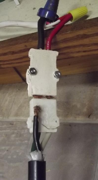 I had been
thinking about the extra-large "T-plug" and "T-socket" I had made to
handle higher currents for heavier loads, which I had installed under
the kitchen sink to plug in a 2700W AC inverter to run fridge and
freezers during power outages. The socket was porcelain, tho I found
nylon 3D printer filament later. (I didn't want to use a plastic that
would melt with heat!) They don't mate very well and they
were hard to make. But I only rate those little T-plugs & sockets
at
about 20 amps or so for general use. How to get a higher current
rating? I decided to try to make a new higher current standard by
doubling up the
regular T-plugs and sockets.
I had been
thinking about the extra-large "T-plug" and "T-socket" I had made to
handle higher currents for heavier loads, which I had installed under
the kitchen sink to plug in a 2700W AC inverter to run fridge and
freezers during power outages. The socket was porcelain, tho I found
nylon 3D printer filament later. (I didn't want to use a plastic that
would melt with heat!) They don't mate very well and they
were hard to make. But I only rate those little T-plugs & sockets
at
about 20 amps or so for general use. How to get a higher current
rating? I decided to try to make a new higher current standard by
doubling up the
regular T-plugs and sockets.
New Double Current (40A) Connectors Standard
So here is the new standard: for 40 amps, two T-plugs (two
T-sockets) will be set beside each other, spaced 12.0mm apart. For 60
amps, three, each 12mm apart would be the next logical configuration.
Wires for 40 amp plugs - at least #12 AWG if not #10 or #8 - are more
than heavy. (And wires across a building to wall outlets should be
still heavier.) 60 amps is even worse.
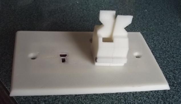
Wall Outlet Plate With New Double
Socket
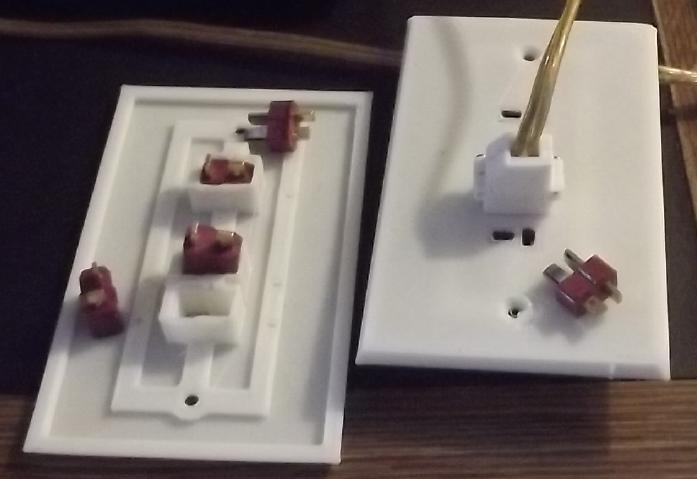 [22nd]I moved
two of the sockets on the 3-outlet wall receptacles to 12mm spacing.
They can plug in two regular appliances or one higher powered appliance
with a double plug. I put the 3D printer to work and made one.
A receptacle with a double socket should
only be installed if the wires from the power source are heavy enough,
like #10 or #8 AWG.
[22nd]I moved
two of the sockets on the 3-outlet wall receptacles to 12mm spacing.
They can plug in two regular appliances or one higher powered appliance
with a double plug. I put the 3D printer to work and made one.
A receptacle with a double socket should
only be installed if the wires from the power source are heavy enough,
like #10 or #8 AWG.
Double (40A) Plug & Socket
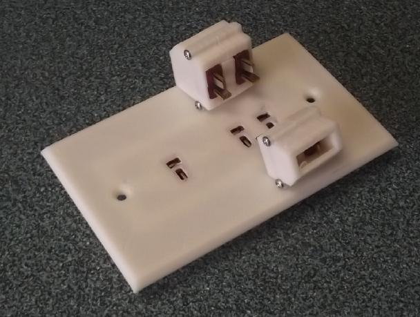 Then I designed and 3D printed a double plug shell to fit into it. It
plugged in perfectly. But it seemed too small for heavier wires. So I
increased the whole size and printed a second one.
Then I designed and 3D printed a double plug shell to fit into it. It
plugged in perfectly. But it seemed too small for heavier wires. So I
increased the whole size and printed a second one.
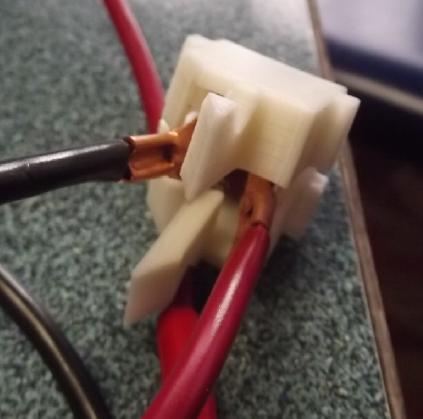
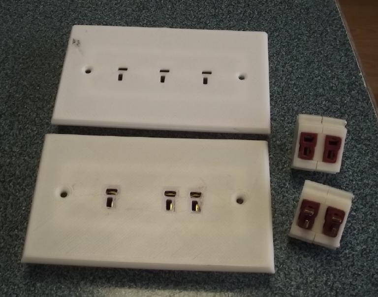 I used that
file as a template and with minor changes did a double socket shell for
heavy in-line
cords/extension cords.
I used that
file as a template and with minor changes did a double socket shell for
heavy in-line
cords/extension cords.
(If the building wiring to a wall plate can't handle heavy loads, the
original plate with evenly spaced sockets should be used.)
 At this point
I realized that there should be a way to clamp heavy wires to the
shells, and I added an extension to tie-wrap the wires to.
At this point
I realized that there should be a way to clamp heavy wires to the
shells, and I added an extension to tie-wrap the wires to.
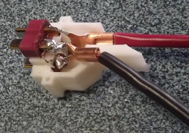 I tried
soldering #10 AWG wires to the plugs. It was a mess. It just seemed
ridiculous trying to solder such heavy wires to such tiny terminals,
and especially paralleling two such sets of terminals. In the vise the
center spacer melted with the heat and became narrower. (The nylon
T-plugs didn't melt even with soldering temperatures on their terminals
- which is why I insist on nylon - or porcelain.)
I tried
soldering #10 AWG wires to the plugs. It was a mess. It just seemed
ridiculous trying to solder such heavy wires to such tiny terminals,
and especially paralleling two such sets of terminals. In the vise the
center spacer melted with the heat and became narrower. (The nylon
T-plugs didn't melt even with soldering temperatures on their terminals
- which is why I insist on nylon - or porcelain.)
So I took it apart and changed tactics. I took a couple of
crimp-on ring lugs, chopped off the bottom of the rings, and soldered
the ring sides to the pins. The wires crimped into the connectors. I
still don't much like it. Hmm...
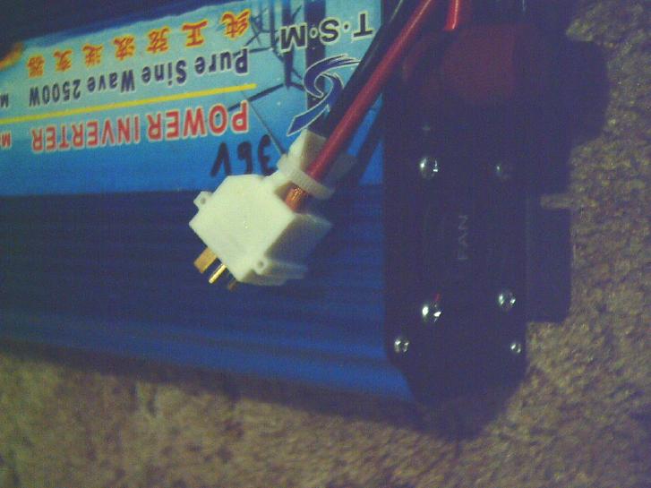 Double plug on 2500W inverter
Vertical Orientation?
I started thinking that the plugs would be nicer oriented
vertical: ground down, "+" up. Rather than change the plate, I mounted
an electrical box horizontally in the cabin. (With some fudging - they
are definitely not made for that orientation mounted to a wall stud!)
Next Steps
Of course I did this for my immediate need - the 36V DC
system I want to put in my cabin. Now I should duplicate all this for
the 12V mini-T-plug system, which, however much I promote 36 volts DC
as the optimum voltage for buildings/RV/boat/off-grid, will undoubtedly
be far more popular. But I think I need a better way to attach heavy
wires. The "Giant T-Plug" wasn't such a bad idea - at least the pins
and shells were a more appropriate size for connecting heavy wires. It
needed or needs to be manufactured, not cobbled together by hand.
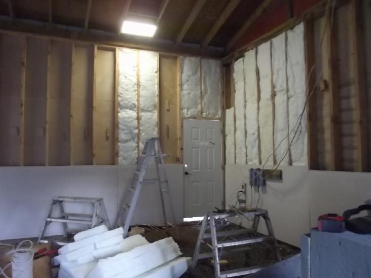
Cabin Construction
This continued to occupy the bulk of my available time.
I am shocked to find that I can't buy cellulose loose
fiber insulation in Northern BC, period. I could only get it if I
bought an entire semi load. It was freely available in Victoria in
1977, over 45 years ago. Having "discarded" my lawn grass fill for
garden mulch (R3 per inch - having decided in favor of buying cellulose
fiber R4 per inch instead) I am utterly forced to insulate the cabin
with costly, un-environmental fibreglass wool batts, which I detest.
(R3 to 3.6 per inch)
And why aren't there cellulose fiber insulation batts?
Wouldn't they be really popular compared to fibreglass? It turns out
that "Wood Wool" batts are in fact common in Europe. Here in North
America we have in many ways technologicly fallen behind the times.
A roll-up garage door I had purchased over the phone at
Home Depot in Prince George was resold to someone else before Dave
could pick it up and deliver it. I found out for sure when Dave showed
up (with my lithium-iron phosphate batteries) on the 27th. The next day
I "scored" some brand new furnace duct from the refuse transfer
station. Thin, shiny, galvanized sheet metal. I decided I could use
that for the outside metal skin and make my own /* */ door. One can
buy the hardware pieces on line and have them sent in the mail.
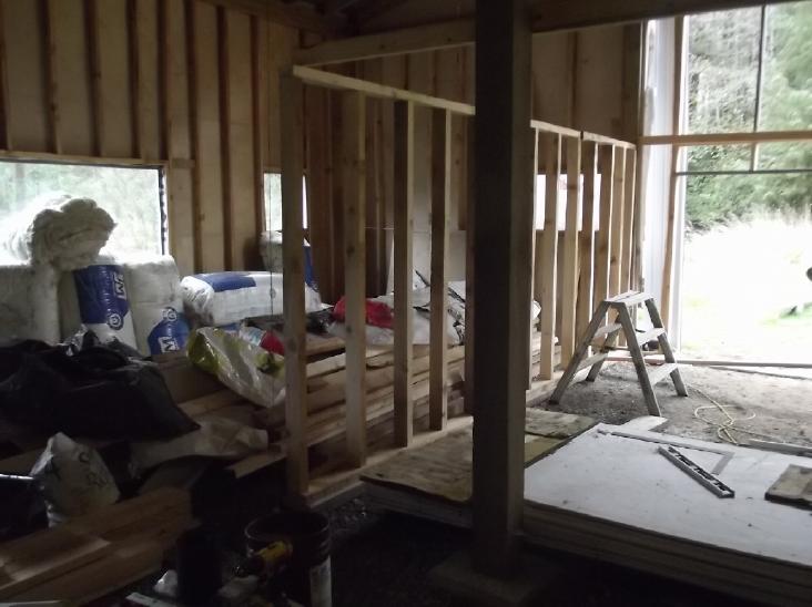 Meanwhile carpenter Dan helped me a couple of times with the design and
construction of the inside of the garage and upstairs room. I used my
handheld bandsaw mill to cut nine 2 by 4s (& three 2 by 6s) from 6
by 6 beams I had in my lumber stacks. We cut them to length on the
29th. (Each one was just the right length to make two wall studs, with
just enough left to cut the chainsawed ends square.) The next day I
screwed the frame together for the inner wall of the garage, then in
the afternoon Dan came by again and we raised it and screwed it into
place.
Meanwhile carpenter Dan helped me a couple of times with the design and
construction of the inside of the garage and upstairs room. I used my
handheld bandsaw mill to cut nine 2 by 4s (& three 2 by 6s) from 6
by 6 beams I had in my lumber stacks. We cut them to length on the
29th. (Each one was just the right length to make two wall studs, with
just enough left to cut the chainsawed ends square.) The next day I
screwed the frame together for the inner wall of the garage, then in
the afternoon Dan came by again and we raised it and screwed it into
place.
Dan suggested tongue and groove flooring for the second
floor. Sure enough, One inch T & G (mixed hemlock, spruce, pine)
was considerably cheaper than
plywood, at the AbFam sawmill at Port Clements.
(Sounds like some mega corp?... actually = 'Abbot Family')
On the 31st I bought
styrene foam insulation for the cores for the door sections at the
local building supply. Gasp! 200$
for three pieces! I had thought if I had to make my own door, with no
windows(!), it was at least going to be cheap.
Hydro Dams Versus River Flow Hydro
I saw a video (youtube) about dams being removed from
rivers, especially two on one river in the Pacific Northwest, where
major runs of every type of Pacific salmon had been eliminated by them
for many
decades. These dams had been made to provide electricity to some
long-gone mining operation. (or was it logging?) Using fish hatcheries,
the salmon and much
wildlife on land that salmon support are coming back now, and forests
on the lands that had been flooded. And a sandy estuary reappeared at
the mouth of the river. They said the life of a hydro
dam is about 60 years. Considering the cost, engineering and effort to
build one, I
was surprised, almost shocked, to hear it was so short. They said a lot
of dams were now
in poor condition and showed a couple that had failed catastrophicly,
caught on surveilance video. Solar installations are expected to last
almost as
long and are surely a bargain in comparison.
This makes me think again that smaller anchored, floating
hydro
power units distributed up and down the river would be a cheaper, safer
and more environmentally friendly alternative, in spite of the upkeep
and connections that would obviously be required for each unit. (And
hey, "smaller" doesn't have to mean "tiny" units in a large river.) For
small streams, flow turbine installations can even be mounted on a bank
and
the turbine (whatever type) lowered into the water. The big advantage
to dams is the ability to hold back water in rainy months for use in
dry months. But now solar power is likely to considerably reduce the
need for hydro power in the dry, sunny months. Floating units
could be shifted to optimal positions as required with changes to the
river's course and flow. I would expect that they could in the
aggregate provide
as much power as a single hydro dam site - maybe more. Floating power
units could be produced in
considerable volume as "standard" items. In fact, floating units
presently being production prototyped for tidal flows might be as
easily employed in larger rivers. Unfortunately (and somewhat
puzzlingly) I don't see that one can actually order a floating unit -
small or large - as of yet.
And yet here we are in BC, building the Peace River "Site
C" dam, flooding a huge tract of land for a stupendous single "make or
break" undertaking that could more
economicly be done piecemeal with floating units - or with multiple
solar panel installations
much closer to where the power will be used. "Site C" has been talked
about for decades, and yet a dam is only expected to last 60 years? If
it had been built in the 1980s its life would already be 2/3 over?
(IIRC I suspect it has
more to do with political donors having bought the land to be flooded
(& along the power line route?) for a song to hold for ransom,
so the public would have to pay them handsomely for it, than with
actual calculated power economics. I can't remember just what I heard
years
ago about that.)
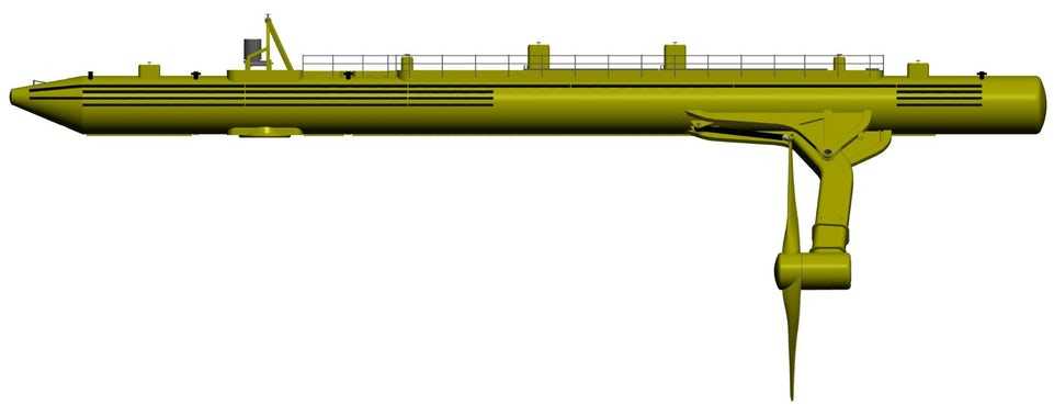
Floating units could also be used in many tidal flow
energy situations. Masset Sound here would probably be a fine place for
something like "Orbital Marine" types.
It flows like a great river in and out with the tides, and this island
could really use that power instead of burning mind boggling amounts of
diesel fuel. Here are a couple of designs.
 This Nova Scotia design
could be good
for shallower river or tidal flows.
This Nova Scotia design
could be good
for shallower river or tidal flows.
(Yikes! It seems that as of this April, Sustainable Marine
Tidal
Power has thrown in the towel on this project because after
5 years of discussions they still can't get approval from DFO to deploy
the unit in Minas Passage in the Bay of Fundy for
trials, notwithstanding government project funding and approval from
all other
Federal and Provincial departments. DFO
wants "more information". I'll hazard a guess that they want to know
things
that can't be known in advance and which
will still be hard to determine for a while even during operation, like
the
exact effects on each fish species in Minas
Basin. This is not fracking or damming a river or building something
permanent! That's what trials are for!)
 The Orbital Marine
designs need pretty deep
water. (Newer units are better designed & up to 2 MW.)
The Orbital Marine
designs need pretty deep
water. (Newer units are better designed & up to 2 MW.)
In
Passing
(Miscellaneous topics, editorial comments & opinionated rants)
Israelstine
I saw this article on Zerohedge.com :
Warnings About Alarming Pre-Oct 7 Hamas Activity Ignored, Say Israeli
Surveillance Soldiers. [Egypt also warned Israel.]
https://www.zerohedge.com/geopolitical/warnings-about-alarming-pre-oct-7-hamas-activity-ignored-say-israeli-surveillance
Apparently the Israeli government "didn't want to know" what was
building. That means that Netanyahu and the Israeli government in fact
weren't "reacting to a surprise event" when Hamas attacked -- they knew
all about
it long in advance and were waiting for it to happen - perhaps egging
it on. It would be a convenient excuse to implement their own violence,
perhaps to erase the whole Gaza strip by killing or driving out the
whole 1.2 million inhabitants.
As I remarked to a friend even before I
read that all intelligence had been "ignored" for weeks before the
Hamas event, "Something is wrong with this picture. It's like it was
all set up as a 'false flag' or something for Israel to justify
attacking Gaza."
Notwithstanding all this, I watched a "pro-Israeli" video
which pointed out some "lies" within the maps showing "ever-increasing
Israeli territory" versus "ever shrinking Palestinian territory". Vast
stretches of uninhabited desert were shown as transferring from
"Palestinian" to "Israeli" in 1948 when Israel became a nation. And
apparently most property transfers [at least in the earlier years?]
were purchases by Jews, not thefts. And as he spoke, I remembered
events in the
news I had long forgotten from decades past which verified that there
was much truth to his arguments. Israel has indeed maintained a
democracy and a higher standard of culture and governance for its
people than its autocratic Arabic neighbors. And I learned a couple of
new things. There was no nation of Palestine, nor had there been. The
area was long under the Ottoman Empire, then was a British Protectorate
until the UN granted Israel nationhood. The "Palestinian Protectorate"
included what is now Jordan, and the entire population around 1920
(IIRC) was about 670,000, which had always included a Jewish minority.
The "West Bank" (of the Jordan river) had been part of
Jordan and Gaza part of Egypt - neither Israel nor Palestine - until
the 1967 "six day war", where Egypt, Syria and Jordan, led by Egypt,
plainly intended to attack and annihilate Israel. Israel made a
preemptive strike on Egypt, wiped out its air force, took Gaza and the
Sinai
Desert peninsula, the Golan Heights and the West Bank from
the would-be attackers. In the West we cheered for Israel turning the
tables on its hostile neighbors and in so doing saving itself.
Israel kept the Golan Heights and the West Bank as
strategic buffer zones in case they were attacked again. Previously
Israel was only 12 miles wide in the middle, easily cut in two. They
gave the Sinai back in return for peace with Egypt, but they kept Gaza,
which cut into the Israeli coastline. (In fact, when Syria invaded in
1973, having the Golan Heights probably saved Israel again. To
everyone's surprise Israeli jets were easily shot out of the sky by
Syrian
missiles and the tank battle in the Heights was a near run thing. The
Syrians gave up just as the Israelis were about out of ammunition.)
But in taking these lands in 1967 Israel acquired many
Palestinians, and no one else wanted them or would have them. The
Egyptians won't let Gazan Palestinians cross the border into Egypt.
Jordan didn't want to accept those of the West Bank. Attempts to have
Palestinians rule - or at least police - themselves in decades past in
the
West Bank
seemed to be a failure. As I recall Israel had to resume policing, and
terror
attacks against Israelis continued. And the problem isn't entirely
unique to
Israel: Lebanon has had Palestinian refugee camps since 1948(!) where
conditions are said to be appalling, and Palestinians aren't allowed
Lebanese citizenship nor to own property. Why do their fellow Arabs
refuse to fellowship the Palestinians? In the 1970s Palestinian PLA
guerrillas controlled southern Lebanon. (Syria stepped in militarily,
but Lebanon would not accept being made part of Syria.) Hamas still
says it wants Israel erased from the map, which makes negotiations and
compromises near
impossible.
Netanyahu's hard policies have not helped. The
Israelis had managed to kick him out themselves at one
point, and there have been Israeli protests about his
(un)constitutional actions since he
got back in. Now apparently Hamas is treating its Israeli prisoners
quite civilly, to the point that Israel doesn't want them back, since
their stories contrast unfavorably with Israel's own war crimes
against civilians in Gaza.
The problems are thorny and other nations seem destined to
make the conflict international, and once again the survival or erasure
of Israel as a state may become the primary issue. (As September ended
it seemed Israeli forces invading Gaza were actually being beaten by
Hamas itself, their tanks getting blown up. Perhaps that will forestall
foreign intervention?)
I am so glad I'm here, so far away from places where too
many people are too filled with hatred, bigotry and intolerance, and
violence is too often used to "settle" disputes! When will seasoned
judgment,
understanding, compassion, equality, love and peace come to all?
Scattered
Thots
* Here's another image of our moon's Antarctic (~ -70° latitude),
this one from the
Pragayaan rover... but still in black and white! Is it really
just drab and gray, or is it filled with vibrant colors? To my eyes
there seems to be a lot of "3D" vertical relief and fluffy stuff here,
and some long thin forms, not
just dust and rocks scattered flat on the ground. Soft shapes hang over
the edges of
craters. And it must be remembered that whatever it is, it seems to
have huge insulating value. The temperature drops from around +15°C
at the surface to -10°C just 8 cm underneath.
Does no one even remark on these things? Why is no one
excited? How much do I have to contribute to somebody's space
program to get them to spring for a $39.95 color camera?

* In French they say "vingt-et-un" ("twenty-and-one", 21). That at
first
struck me as silly, adding the extra "and". Also inconsistent since 22
(and up) is "vingt-deux", "vingt-trois"... without the "and" in the
middle. Then I realized that's really what we do in English, except we
seem to have
replaced the French "and" (et) with the Spanish "and" (y). So when we
say "twenty-one", perhaps it's really "twent-y-one"... or at least it
may have
started from that.
* Our English number naming system is pretty logical except it breaks
in the values 13 to 19. "Teen" is no doubt a way of saying "ten"
without the hearer mistaking (eg) "sixteen" for "six ten". But instead
we mistake it
for "ty" - "sixty". Why is the tens digit, in this range alone of all
numbers, spoken after the ones digit instead of before? Of
course we learn all manner of weird verbage as children and don't give
it a thought. But the similarity of sound to other numbers can lead to
mistakes - "eighteen" and "eighty", or "thirteen" and
"thirty". In the French example again (the only other
language I can count to 10 in), "regular teen" numbers are spoken the
"normal" way, tens digit first:
17 dix-sept (ten-seven)
18 dix-huit (ten-eight)
19 dix-neuf (ten-nine)
We could "easily" [can anything like this ever be "easy"?]
change our English verbage:
17 teen-seven
18 teen-eight
19 teen-nine
The above would preserve the "traditional" name "teen",
for the same numbers. Or we could make it conform better with the
larger two digit numbers with "y", as well as making it clear we are
using the
new system:
17 teeny-seven
18 teeny-eight
19 teeny-nine
Unlike the otherwise logical "tenty" (where 15 would be
"tenty-five"), "teeny" isn't easily confused with "twenty" (which is
also
a good reason to leave a second "t" out - not "teenty").
ESD
(Eccentric Silliness Department)
* Narcassist: Someone who aids narcotics agents in their valiant
struggle against people trying to obtain drugs not officially
prescribed by their doctor (who sometimes may not be willing to
prescribe something, however benign or potentially useful, for fear of
potentially losing their medical
license).
* If what was "Eastern Ukraine" until 2014, or "Novorussia",
should decide to form their own country, I have the perfect name for
it: Chornorus (Black Russia). It is south of Belarus (White Russia) and
north from Chorno More (Black Sea).
But the locals probably have other ideas.
"in depth
reports" for
each project are below. I hope they may be useful to anyone who wants
to get into a similar project, to glean ideas for how something
might be done, as well as things that might have been tried, or just
thought
of and not tried... and even of how not to do something - why
it didn't
work or proved impractical. Sometimes they set out inventive thoughts
almost as they occur - and are the actual organization and elaboration
in writing of those thoughts. They are thus partly a diary and are not
extensively proof-read for literary perfection, consistency,
completeness and elimination of duplications before
publication. I hope they may add to the body of wisdom for other
researchers and developers to help them find more productive paths and
avoid potential pitfalls and dead ends.
Electric
Transport
Miles "Mini Cargo Van EV": for now, Fixed ratio Drive
[14th] I assembled the shaft assembly under the truck again and put in
the
two pieces of steel for holding the 5 to 1 planetary gear body, and
marked
where to weld them together. The angle iron piece had been bent to
sharper than a right angle, but I managed to right it with a large vise
and two 15 inch crescent wrenches - one on the end of the other to make
a longer handle.
The bolt holes on the planetary body to attach to the
lower piece
had
little clearance - no room for a nut or a hex head bolt. I am about out
of socket head machine screws and can't buy them here. Then I got the
idea to grind 1/4 of the way around the hex head on the bolts, almost
down to the shaft. Not only do they slide into the slots, but they
can't turn. It'll be easier putting the nuts on.
[22nd] I welded the two pieces together, having brought the MIG welder
into the house from the cold shipping container (storage) a few days
previously to be sure it was dry. My welding still looks like crap
(only somewhat mitigated by considerable grinding), but I think I've
thrown on enough bead that they won't come apart.
While I'm welding I have a really hard time seeing what's
actually being laid down with the darkened welding helmet on.
[30th] In the late evening after
working on the cabin most of
the day as usual, I finally installed the transmission with the fixed 5
to 1 planetary gear in the truck. I had to take the plate out to the
shop for a little filing and grinding, and I pounded the steady bearing
another 3 or 4 mm along the motor-to-planetary shaft to get it better
into its mounting. But mostly it
went pretty smoothly. My back has been much better of late, and
I didn't suffer in spite of spending something like an hour underneath
the truck
adjusting and doing up bolts and set screws.
But now, it seems like
really primitive technology to lock the planetary gear body in place,
compared to having the driving forces smoothly balance magneticly and
to have the reduction ratio smoothly drop to near 1 to 1 as vehicle
speed
increases!!!
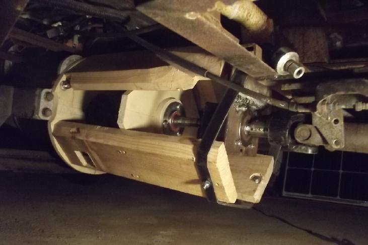
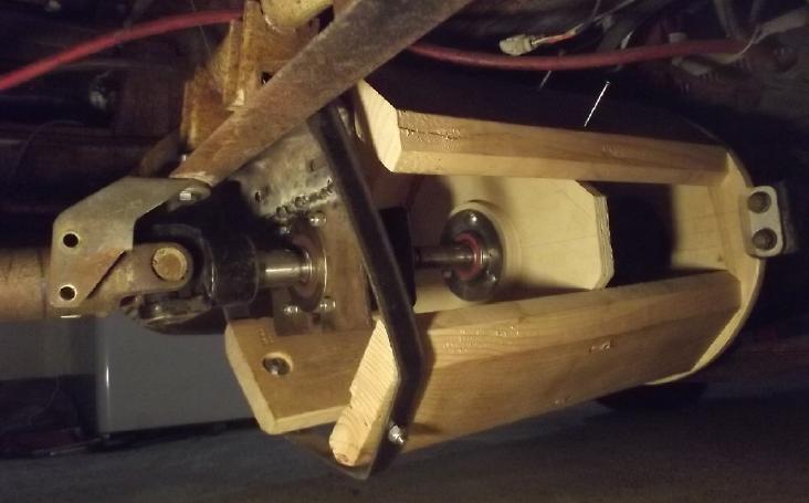
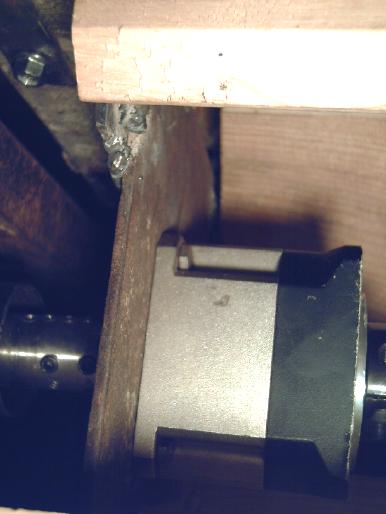 Another view, attempting to show
how the plate
holding
Another view, attempting to show
how the plate
holding
the planetary body & transmission rear "cradle"
bolts to the frame - with no rubber cushions. (bolt, top left)
It ran fine in the garage.
It hopped over a 2 inch board.
I never
took my foot off the brake and let it coast freely, or I'd probably
have hit the door or back wall. Hmm, I still haven't closed in the
"transfer case". How far should I drive it without doing that? OTOH I
can video the operation while it's open.
[31st] In the morning I ran it around a bit on the circle driveway. It
sounded rough. That's probably because the planetary body is bolted
direct to the frame with no rubber padding. I hope the shaft parts are
well aligned. It sounds "fast", even at low speed. With 5 to 1
reduction gear (total 11 to 1) the motor is actually turning faster
than when it was total ~4.5 to 1 originally. It also seems much faster
even at low speed than with the variable magnetic torque converter,
even when it had the inadequate alume alloy rotor for magnetic
interaction. Then, I was certainly traveling faster in the driveway
with much less noise and "roughness".
I should put a video camera underneath and make sure all
looks good down there when I drive it. And I wonder if there's any way
to fit in some hard rubber blocks like most car engines and
transmissions use in their mountings to cushion the vibrations.
Next: getting the Curtis motor controller programmer to
talk to the Curtis motor controller. With the higher ratio (total ~11
to 1 - and the locked planetary body) the regen braking just by taking
my foot off the "gas" is fierce, and the top speed extremely limited.
The Long-Planned Unipolar "Electric Hubcap" Motor
New Idea: Hallbach Stator
Configuration?
When you think you know everything,
some exciting new idea that may advance the technology in a leap comes
along. First
there were the several novel things I've already done for my previous
axial
flux motors (2008 to 2012 or 2013) that made them highly efficient with
the least iron and weight. Then there's the unipolar idea (needing its
own new six phase unipolar motor controller for a 12 coil/8 magnet pole
motor). If
nothing else unipolar eliminates iron hysteresis losses. (I also think
I can
make the unipolar motor controller simpler & more reliable.) Next
somebody thought up a Hallbach
configuration of permanent magnets in the magnet rotor to increase the
magnetic interactions with the stator as well as eliminate the need for
a heavy steel rotor disk to gain
sufficient back iron to conduct the rear field, and showed it on
Youtube. I used this in the
magnetic torque converter to excellent effect. This all seems to
portend potential for a great motor. How could it get any better?
Now a new idea in a youtube video by "Tech Planet" was to
also arrange the stator coils in a
Hallbach configuration, to direct the flux toward the rotor and
eliminate back iron in the stator. I'm not sure that such a motor was
actually prototyped, but the idea seems marvelous - if practical. (A
guy showed a stator with some coils at right angles, but I gathered it
wasn't a working prototype yet.) My iron powder coil cores with the
ilmenite coil wires coating to complete the magnetic circuit also
eliminate the back iron. But this could make it even better. I had
never considered that stator coils might
also be so configured.
One could add sideways facing coils between the regular
coils as was shown, but it looks like it would be tricky to actually
fit them on so there is a gain of performance. So instead I am thinking
the other novel idea, "permanent magnet assist", could fit in ideally
here. With little change to the previous plan,
place permanent magnets on their sides between the stator coils
(electromagnets). Since the coils are only energized in one direction,
every time one is energized, it and the permanent magnets beside it
would make a Hallbach configured stator coil aiming most of
its magnetic field right at the rotor, instead of a typical coil with a
bidirectional field and half of the field going the other way. I should
think this would increase available torque (and hence maximum power),
and could reduce motor coil currents and increase efficiency,
especially under higher loads. Again, and thinking of a heavily loaded
motor driving a vehicle rather than one operating at 95%(?) "peak
efficiency" (generally at around 10-15% of full power), I should think
an
88% efficient motor would
generate half the heat of 76% efficiency and hence be much easier to
cool, as well as adding maybe 10% to the potential vehicle range.
I should mention there was also something else in the
video, about inducing
current into rotor coils and eliminating the permanent magnets and rare
earth materials in the rotor too while still having a synchronous
motor, yet
still attaining high efficiency. (Or is it only high peak
efficiency?)
So far I'm not convinced that would make the best motor to
give longest driving range. Permanent magnets take zero power to
energize. And supermagnets
aren't cheap but neither is copper, and getting the most out of the
batteries is well worth a slightly more costly motor. So I still plan
to use the Hallbach
configured permanent magnet rotor.
But the idea of a Hallbach configured stator coupled to a Hallbach
configured rotor sounds like a fantastic axial flux motor layout!
Perhaps
it's a blessing that I haven't yet found time to build the "Unipolar
Electric Hubcap" motor. It seems I'd only have wanted to change it
again! (I had the rotor cut and fitted it on the trailer stub axle hub,
quite a long time ago now, but stopped there. I was all ready to cut
the magnet placement jig on the CNC router and then epoxy the magnets
onto the rotor, but never got to it - yay!)
Now I have to expand the whole diameter a bit to
accommodate
even 1/2 inch thick magnets between the coils. Another thought is that
magnets could go in the "corners" where the circular toroidal coils
have waste space, without the stator taking up any more room than was
already needed. But there's not a lot of space there, and probably it's
not a good
option for a prototype with the rectangular magnets I have.
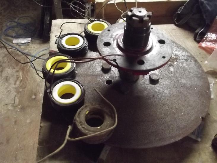 [19th] I took
some spare coils and some steel blocks to pass for magnets (without
them attracting everything), and laid them out on the still unfinished
magnet rotor. In the original layout, the outer edge of the coil cores
align with the outer edge of the magnet rotor. 6 coils alone fit nicely
around one half of the rotor.
[19th] I took
some spare coils and some steel blocks to pass for magnets (without
them attracting everything), and laid them out on the still unfinished
magnet rotor. In the original layout, the outer edge of the coil cores
align with the outer edge of the magnet rotor. 6 coils alone fit nicely
around one half of the rotor.
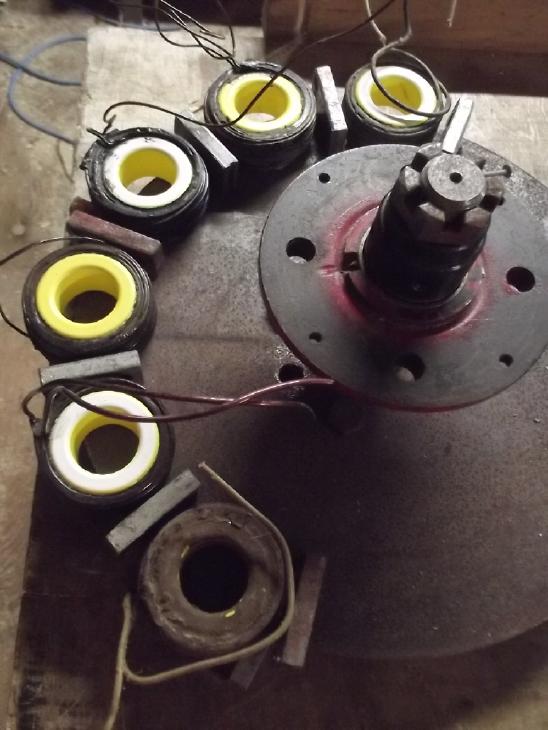 But with a 3/8
inch
"magnet" block between each coil, it seemed the radius had to be
increased by about 1/2 inch.
But with a 3/8
inch
"magnet" block between each coil, it seemed the radius had to be
increased by about 1/2 inch.
I have 1 by 2 by 3/8 inch magnets, but 1/2 inch thick ones
should improve the Hallbach effect. Allowing a bit more space for 1/2
inch, the
radius needed to be about 3/4 inch more. So instead of 326mm (as
made), the magnet rotor will now have to be 364mm (14.33
inches) diameter. Again the outer edges of the coil cores would be at
this diameter, as would the outer end of the magnets. With such a large
rotor diameter and such large magnetic fluxes, as well as more magnetic
elements (12 coils & 16 regular magnets instead of 9 & 12, plus
the sideways magnets) this motor should have far more torque than my
original Electric Hubcap motors.
I had finally rejected the original "permanent magnet
assist" idea as probably not being a significant improvement. But I'm
glad I
heard about it and now have thought of adapting it for this purpose.
Try to
imagine fitting in sideways electromagnet coils where those permanent
magnets are. If the cores were the same height as the "regular" cores,
the wires wound around them would have to be in the flux gap (and wide
tho that is, maybe hit the rotor magnets) as well as going below the
mounting plane. One could make them wider and lower, reducing the
Hallbach effect and forcing the regular coils to be considerably
farther apart, making the motor a still greater diameter and perhaps
with no more
magnetic power. Any or all of those things with "Hallbaching coils"
could be a show stopper for
the whole idea!
I imagine the proportions should
work out pretty much optimally
with the components I have on hand. All I need now is a bigger piece of
1/8 inch steel plate for a new magnet rotor (~15 by 15 inches) -- as
well as
to create all the other jigs, molds and components I've needed all
along.
A way to reduce the diameter a bit would be if I had egg
shaped toroid coils instead of round, still an inch tall, still 2
inches across on the long side but a little slimmer in width. Round is
great coils, but if I was considering mass production it might be worth
making egg shaped ones or having them made. (But it seems to me the
sharp cornered wedge shaped coils used in so many in axial flux motors
just take extra copper for little magnetic benefit. Round/toroid uses
the least amount of copper wire per coil. A "fat egg" toroid shouldn't
be far behind.)
[20th] The weakest point of my previous motors seems to have been
cooling. Although heating up quickly is a general complaint about
lightweight axial flux motors, my Electric Hubcap got hot fast in high
torque tests on the Sprint in 2016 with the Kelly 300 amp motor
controller, and the
Electric Caik outboard, while it didn't seem to heat up very fast
running the boat, didn't seem to expel whatever heat there was, and
gradually got to "I smell hot resin" temperatures. The poor heat
dissipation combines with the fact that the plastic body parts are only
rated
for 65°C, where steel laminate & motor varnish motors can get
much
hotter without problems. I think this time I'll design the housing so
it will hold a fairly powerful four inch computer type fan, with
passages to blow air across the coils whenever the motor is running.
Other
"Green"
& Electric Equipment
Projects
T-Plugs & T-Sockets (36V DC Wiring)
The cabin is to be wired with 36V DC with 290 amp-hour
lithium-iron phosphate batteries, both to be "quasi off grid" and since
I am trying to eliminate 60Hz electrical fields inside it. AC power
fields seem to be the cause of tinnitus, and mine is awful. (Again the
finished cabin will have - and mostly already has - metal roof, metal
outside walls, metal doors and 2 inch chicken wire screens over the
windows, all grounded, to damp down the field from the nearby 14,400 V
AC power line, and almost no 120V AC wiring inside - one plug right by
the door where the AC comes in. Even that can be unplugged from
outside. The fields should be reduced by around 60 dB.) On about the
18th I wired in a 30x60cm LED flat panel light on the ceiling near the
darkest northeast corner, with a light switch by the door. It was a
typical switch in a typical electrical box with a typical cover - no
reason to do anything special just because it was 36V DC. I used skinny
speaker wire up the wall stud from the switch to the panel, something
one would never do with 120V. I used a piece of old extension cord down
the wall to what will be under the floor when it's finished, and put a
T-plug on the end. It can just be plugged into whatever cord I run
under the floor from wherever I put the batteries. It's really nice to
have light in that dark corner.
I
had been thinking about the extra-large "T-plug" and
"T-socket" I had made to handle higher currents for heavier loads,
which I had installed under the kitchen sink to plug in a 2500W AC
inverter to run fridge and freezers during power outages. They don't
mate very well and they were hard to make. And of course the inverter
can't plug in anywhere else without changing the plug. But whatever the
model airplane people rate them at, I don't think those little plugs
& sockets should be employed in continuous use in home, RV or boat
applications for more than about 20 amps or so. As with 120VAC
circuits, transient higher currents (eg, for fridge compressor or other
motor startup) are permissible. 15 amps at 120 volts (for 1800 watts)
is 50 amps at 36 volts. How to get a higher current rating? I decided
to make a new higher current standard using the regular T-plugs and
sockets by doubling them up.
New Double Current (40A) Standard
Connectors
So here is the new standard: for 40 amps, two T-plugs (two
T-sockets) will be set beside each other, spaced 12mm apart. For 60
amps, three, each 12mm apart would be the next logical configuration,
but I'll ignore that idea for the moment.
Wall Outlet Plate With New Double Socket
[22nd] The
first thing I did was move two of the sockets on the
3-outlet wall receptacles to conform with this. These two 12mm spaced
sockets can plug in two regular appliances or one higher powered
appliance that has a double plug on it. I put the 3D printer to work
and made one. It worked fine but was only marginally satisfactory from
a manufacturing quality point of view, with gaps between the strips of
plastic. I tried adjusting printer extrusion density settings that were
so simple with the old rep-rap. (Just send something like "m90 ?##". If
only I could remember what "?" was, I could - probably - just insert it
at the beginning of the G-code file.) Instead the procedure was go to
this menu, do this, then this, but when I was done it still produced
the same 'slice' file with the same "8.27 meters of filament", which
should obviously be more to print thicker. I adjusted a couple more
things, to slow down the print of fine details on the first layer to do
a better job, and tried a print. NO changes: thin traces; same fast
printing mucking up the surrounds of the blade holes! Another hours
twiddling settings, another hour and a half print time, and no better -
not even any different - from the first one! The original problem was
probably that the filament was about 1.65mm diameter instead of 1.75mm,
but setting to that size in "printer settings" changed nothing.
12mm is far enough apart to plug in two single plugs, so
why didn't I put all three sockets 12mm apart to allow for single,
double or triple plug usage? Well presently I'm not planning to make
triple
T-plug/socket units for up to 60 amps. The huge wire size of #6 or #4
AWG wires to carry such currents just seem incompatible with such small
connectors. (One could of course pigtail smaller wires from the plug
pins to the heavy cable... but.)
To have even a double socket (presumably for up to 40
amps) requires heavy wire from the power supply. A receptacle with a
double socket should only be installed if the wires from the power
source are heavy enough, like #10 or #8 AWG.
Double (40A) Plug
[23rd] Next job was a double plug shell to fit into it for higher amps.
I extended the side walls of a single plug until each side would hold a
whole T-plug instead of just half of one, and in fact hold them 12mm
apart if they were pushed right to the closed side. Then I designed a
filler piece to hold them there. Luckily I had bought some tiny
diameter screws in an assortment box and there were some long enough to
go almost right across and hold securely. (m2.2 - 20mm)
I
printed one and it plugged in perfectly. But I didn't
see how (eg) #10 wires could be soldered on and fit in. So I increased
the whole size of the shell to have more space inside for fat wires and
wires bridging the like polarity pins, and printed a second one. On
viewing it and plugging it in I made a couple of tiny dimensional
changes for a better fit. (Here I watched another video and figured out
how to get more filament out of the extruder: the essential parameter
was called "Flow", meaning "flow rate" - the amount extruded per mm of
travel. The tight fit of the center filler piece with no changes from
previous was probably the result of putting down more plastic - this
time a sufficient amount for a nice result.)
Double (40A) In-Line Socket
After that, a double socket shell for heavy in-line
cords/extension cords. This is the easiest one - it's the same as the
double plug except the T-socket depth is 10mm instead of 6.5mm. Just a
few numbers need to be changed.
[27th] I designed and printed it. Next day I made a couple of small
dimensional changes to the center filler piece for both plug &
socket. They ended up with just an ounce of slack the T-plugs/sockets
could even wiggle slightly. They fit better and plugged together much
more easily.
At this point I realized
that there should be a way to
clamp heavy wires to the shells, and I started thinking about how best
to accomplish this. No doubt the same design can again be modified and
pasted in for both. The wall plates don't need anything. (Then there's
"click-lock" that would be good to have for in-line cables that you
don't want to have come apart with vibration in a vehicle or other
disturbance. For both single and double connectors...)
Vertical Orientation?
Having made quite a few wall plates with the sockets
horizontal, I started thinking that they would be nicer vertical.
Ground down, "+" up. It's not so hard looping the wires in the wall
plate a bit instead of having the "+" ones in a straight line. Or...
one could mount the wiring boxes horizontally and then the horizontal
sockets would be vertical? This would be a bit unusual in house wiring
practice, but why not? And the plugs would be beside each other instead
of above and below - easier to see which wire goes to what.
I mounted an electrical box horizontally in the cabin.
They are definitely not made for this orientation. The clamps come out
the ends only and there are no mountings on the ends. I bent four
mounting ears by 90 degrees to screw one end to the wall stud, and had
to loop the #12 cable back from the outer end to the stud.
Next Steps
Of course I did this for the 36V DC system I want to put
in my cabin. Now I should duplicate all this for the 12V mini-T-plug
system, which, however much I promote 36 volts DC as the best voltage
for buildings/RV/boat/off-grid, will undoubtedly be far more popular.
(Again, at the risk of being tedious, 36V nominal is still the highest
really safe voltage. Electrocutions around this or lower appear to be
"virtually never". Under charge "36V" can be up to about 44 volts,
whereas "48V" nominal can be up to 58 volts - getting up there, nearly
half of AC line voltage. But 36V needs 2/3 of the copper wire cross
section of 24V and 1/3 of 12V, and has lower losses. [For a resistive
load, a 1V drop through the wire at 12V is 16% power loss. A 1V drop at
36V is 5.5%.] 40V, which is about where lithium "36V" sits if fairly
well charged, is 3 times "12V" and 1/3 of 120V. For reduction to 12V or
other lower voltages, there are many adjustable output DC to DC
converters rated at up to 40 V input which will fry at 48V. And being
DC as well as a lower voltage, it is my solid belief that it won't
induce tinnitus the way higher voltage, low frequency AC appears to.
This last remains to hopefully be demonstrated in my "almost off grid"
cabin.)
[29th] I
designed and printed a new double plug shell with a couple of
extensions to wrap a cable tie around to trap the wires and hold them.
Then I tried soldering #10
AWG wires to the plugs. Since they had to
be
outside the shell to solder them, they had to be held in a vise with
the center spacer between. It was a mess. With enough solder and heat
they connected, but it just seemed ridiculous trying to solder such
heavy wires to such tiny terminals, and especially paralleling two such
sets of terminals. The center spacer melted and became narrower. The
nylon T-plugs didn't melt even with soldering temperatures on their
terminals, which is why I insisted on nylon, especially for the sockets.
So I took it apart and changed tactics. I took a couple of
crimp-on ring lugs, cut off the end of the ring, and soldered the ring
to both pins. The wire would
crimp into the connectors.
I put it on my 2500W
inverter, but I'm still not happy with it (esp. with the copper
sticking out)... looking for a better idea for connecting the wires.
Cabin Construction
 On the 15th I
decided to just assume I could "hack" the
bottom off the garage door and tracks to make it shorter and resumed
construction,
starting
with lowering the door opening to 6 feet 1 inch. Walking through it
there seemed to be adequate clearance - for me. The door had better
roll up and sit at the full height. Assuming 11 inches for the hardware
and door when rolled up, that puts the garage ceiling at the now inner
2 by 4, seven feet above the opening level. (I assume I'll pour
concrete and make the garage floor that same level some day. Until then
the gravel is just a bit lower.)
On the 15th I
decided to just assume I could "hack" the
bottom off the garage door and tracks to make it shorter and resumed
construction,
starting
with lowering the door opening to 6 feet 1 inch. Walking through it
there seemed to be adequate clearance - for me. The door had better
roll up and sit at the full height. Assuming 11 inches for the hardware
and door when rolled up, that puts the garage ceiling at the now inner
2 by 4, seven feet above the opening level. (I assume I'll pour
concrete and make the garage floor that same level some day. Until then
the gravel is just a bit lower.)
That leaves the maximum amount of headroom - still minimal
- for the room above.
Then I cleared out the
entire cluttered northeast corner,
1/4 of the space, with a view to putting in the plank floor. I brought
in two more lengths of soaking wet 4 inch thick spruce "under floor"
slabs to dry - I should have done that in the summer if not a year ago.
Then I decided I should start doing the walls first. If
they were gyproced and insulated (along with the ceiling), the space
could reasonably be heated even without the floor being done. It looks
like I have no real choice but to use that horrible, costly fiberglass
crap instead of cellulose fiber.
( I wonder why no one makes cellulose fiber as batts instead of
just loose fill? If the fibers couldn't be made to hold together with a
bit of some glue (perhaps sprayed on), then some thread - cellulose
(rayon) perhaps - or mesh could weave it all together, with an outer
"cloth" mesh layer if required. A special loom could do whatever it
needs to make nice batts. Seems like an exciting potential product to
me: Higher "R" value, cheaper, non-itchy, environmentally benign
(actually biodegradable) and with good fire ratings. They would
probably rapidly replace fiberglass batts.
AHA! In a French video (yay for
subtitles/captions), I see "Wood Wool" insulation batts seem to be
common in Europe. As usual the rest of the world has forged ahead of
North America.)
But doing the walls of course means doing any wiring that
needs doing first. (Starts to remind me of trying to remodel my first
house where whatever I wanted to do, something else should be or had to
be done
before that, and something else before that, and something else before
that, until it came full circle back to the original job.)
As mentioned before there will be very minimal 120VAC
wiring, and that shielded to minimize the EM field and hopefully reduce
or eliminate my tinnitus. Instead there will be 36VDC circuits for
lights and miscellaneous things, with DC LED light bulbs and light
panels, DC to DC converters for 12V
items, and all powered by solar panels and a new battery supply. I
expect I'll
want a 120VAC to 36VDC charger for the cloudy depths of winter when
almost no solar power is available. (As shown in the solar log under
"Electricity Generation", daily solar has suddenly gone from 10+ KWH in
sunshine to 2 or 3 in clouds. All compared with 20+ KWH in summer.)
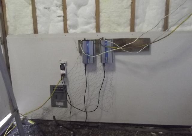 The AC section: Panel with one
breaker (why did
I bother?), one double wall outlet, and
The AC section: Panel with one
breaker (why did
I bother?), one double wall outlet, and
two (unshielded!) cables from the solar grid tie inverters to the watt
meter/KWH recorder.
I had originally planned to have 2 or 3 wall outlets, connected with BX
shielded wire,
but now I think, the less AC wiring there is the better. The 50 foot
cord plugging in the
power tools is certainly a notable 60 HZ EM field (tinnitus) source.
But it's visible and unpluggable -- not wired in, hidden behind drywall
in every wall!
To proceed I immediately need a lot of real, copper
#18 AWG wire for low voltage LED lighting that I thought I had bought
in plenty of time a couple of years ago. Then I found out it was fake:
copper coated steel or something with almost ten times the electrical
resistance of copper. I'll also have some heavier 36VDC wall sockets
fed by #12 AWG wires for heavier loads.
Now I suddenly have to decide where the lights and outlets
are going to be! I think the DC electrical closet will be under the
stairs opening into the garage. I'll have to order some more DC circuit
breakers and things, and a solar charge controller, to outfit it
with.
[24th] I went out first thing in the morning and put in an electrical
box for a 36V DC outlet on the north wall above where I conceive a
counter
might go, and a #12 AWG cable from it down to what will be under the
floor. Then I put up a sheet of gyproc to finish that bit of wall. All
ready for the batteries and solar charge controller! (The batteries
arrived on the 27th. The new charge controller came on the 31st. I
don't know exactly where I'm putting them yet!)
I had been considering whether the garage and the second
floor room over it should be 12x16 feet square, or angled 12x16
tapering to 9(x16) at the inner end. I thought the angled wall could
make the main space look cool. A carpenter friend, Dan, came over "to
look at it" - with tools - and convinced me it should be square. That's
no doubt better - a car in the garage really would need the space and
the larger upstairs room will doubtless be nicer. (Previously I had
helped Dan set up his elaborate solar
system at his very nice off-grid house on a point across the Yakoun
River delta from Port Clements.
[but 25Km to drive to, by logging roads!])
He stayed until mid afternoon and we measured, leveled,
glued and screwed edge boards into place. I owed him (at least!) a tube
of glue and a big jar of deck screws. Then he phoned in the evening
with a couple more valuable ideas how to do the inner wall and the
upstairs floor joists. All that certainly set me on my way! I had been
planning to put off the garage inside wall and second floor, but the
roll-up garage door requires the ceiling joists to mount the tracks on,
so I actually can't finish enclosing the building without it being done.
[25th-26th] I
hung a big nut with a string from the roof ridge to mark
the very center of the building, where I would put a post at the corner
of the
garage & upstairs room.
Here I should have made a 16 foot long concrete footing
where the garage side wall would run. I didn't want to take the time
and effort. Instead I found a big rock with a flat face, shaped like a
bicycle saddle. Instead of pouring a concrete square for the center
post footing, I dug this into place, level with the footing at the
other end of the garage end wall. I piled a little gravel along the
length to make it level all the way across (didn't take much), then I
cut and placed a 16 foot cedar 2 by 8, with tarpaper between it and the
gravel, for the base of the wall. I walked along it a few times and
added bits of gravel until it didn't seem to sag anywhere - or bulge
up. Since it's inside and the sand and gravel floor is pretty dry, and
with the tarpaper under it, I don't expect it will rot during the life
of the building.
[27th] My lithium-iron phosphate
batteries arrived. Great! But Home
Depot had told Dave they didn't have the garage door and he arrived
without it. Ouch! What happened to it? I paid for it. When I phoned the
lady checked to make sure they had it, and said that she would put it
by the service desk with Dave's name for pickup in the 24th. I can
hardly enclose the building without the door. Getting BIG things that
need shipping to this somewhat isolated island can be trying. (450$
additional for the battery delivery, 9 heavy boxes.) If I put up some
fixed cover I'll have trouble taking lumber et al in and out during
cutting and fitting.
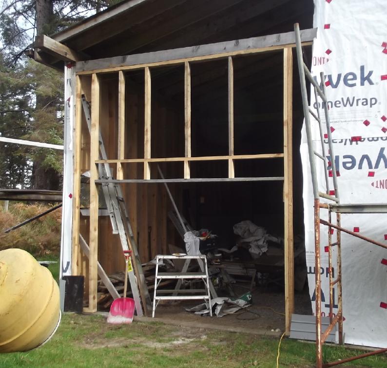
[26th] With my handheld bandsaw mill I cut 2 by 4s for the inside wall
studs from some 6 by 6 beams in my lumber pile (just the right length
for 2 studs from each!)
[29th] Dan and I cut the boards to length and got everything set up.
[30th] I screwed together the wall frame, and later Dan came by and we
raised it. He suggested tongue and groove from AbFam mill for the
upstairs floor, and sure enough at 1.60 $/sq.ft. (for 1 inch
pine/hemlock/spruce T
& G) it's cheaper than 3/4 inch plywood.
Make a Roll-up Garage Door?
[28th] I took my crushed cans & misc metal to the "refuse transfer
station". It pays to do that rather than use the curbside garbage
pickup that I'm forced to pay for annually even tho I never use it,
because
sometimes good things are to be found there. This day I found someone
had just dumped a whole bunch of brand new furnace air ducts for a good
size building, which had apparently never even been installed. (Ouch! I
thought I changed my mind on a whim! This was on a large scale
and a lavish budget. Probably taxpayers' money?) They were thin
galvanized sheet metal 10 x 18 inches, rectangular. Each section was
about 4-1/2 feet long, and they were sitting in assembled lengths
of 4 sections. The sections were joined with folded over strips of the
same metal, screwed on. Some had side openings for smaller branch
ducts, others were clear. I took 3 clear lengths, which I figured gave
me enough square feet for the outside face of the door. If I couldn't
buy a door, perhaps I could figure out some way to make one?
If it had the metal for an outside skin it might have
light 1/4 inch plywood inside face, or maybe 1/8 inch rotary mahogany,
if there is still such a thing. Sandwiched between these would be
pieces of 2 inch thick polystyrene from the lumber yard, and the faces
held with nuts, washers and 2-1/2 inch bolts going right through the
foam, inside to outside. There's a basic lightweight layout for the
main body! Various roll-up door hinges, rollers and other hardware can
be ordered and shipped in the mail, eliminating the large-item shipping
headache.
Better, maybe a layer of polypropylene
("landscaping fabric") for the inside face, epoxied onto
the foam. Epoxied PP strapping at the sides to hold the rollers and
hinges. That would probably be lightest and best. If the door was light
enough, I could probably skip the heavy spring and cables. Or maybe
have the cables attached by pulleys to two counterweights that lower at
the sides at the back as the door is pulled up. And instead of metal
tracks, perhaps I could use wood, 2 by 4s (and some other wood
for the curved section), with the track routed out as a wide slot.
It's starting to sound doable! And I'd save hundreds of
dollars off the 'bargain' door that I didn't get, and well over a
thousand off any other door I've seen on line.
And if the whole thing was my own design, maybe I could
even make it so that it didn't take a whole foot below the ceiling. In
that case the opening could could a little taller than the 6 feet one
inch I had spaced it for. (Yes, I could redo the top of the opening
frame one more time!) OR... since I haven't done the inside wall yet, I
could lower the upstairs floor a bit more and have a bit more headroom
upstairs... or use 2 by 6 floor joists instead of 2 by 4s, which should
make the floor less springy. OTOH, I think I'll stick to the present
plan, leaving room for a commercially made door in case the one I make
doesn't work out as well as I hope.
Caveats The styrene foam 'insulation' panels are 2 by 8
feet. Maybe I should have made the door [6'1" by 9'] only 6 feet tall
by 8 wide? Well, I suppose they can be glued. The one other thing is
that I had ordered a door with windows. How am I going to put in
windows in one of these sections? I suppose I could do without... there
is one side window in the garage space for light. I had better do a
good job of fitting this door: the garage space is part of the heated
structure. Two inch foam in the door is R10, but that won't mean much
if there are air leaks around the weatherstripping or between the
panels when it's closed. The two garage doors in the original house are
no marvels of tight fitting. In fact, one is installed wrong and is
quite a loose fit.
(If the garage was unheated there is exactly the same amount of
unheated wall/floor area to insulate. It would just be inside walls to
insulate instead of the outside, and the second floor's floor instead
of the ground floor. So unlike the garages on the sides the original
house, it would be
virtually pointless to have this garage unheated.)
[29th] Inconveniently, the metal is only 52 inches long - not quite
half way across (54"). I'd have preferred a small overlap. Looks like
I'll have to do more cutting and bending (to flat) than I had hoped. Or
10 by 18 duct is 56 inches circumference. Much better! If I flatten
them all out completely.
[31st] Yow! 66.66$ each (with tax) for 2 inch styrene foam "boards"! I
figured they'd have gone up from the 29.95$ (plus tax) that I had been
paying in Victoria before I moved here, but this was almost too much -
200$ instead of ~100 for just three sheets! Am I going to pay as much
to build the door as the price was to buy that one from Home Depot?
Handheld
Bandsaw
Mill
- some notes
The mill was created in 2018 and appears in most issues of that year.
It was modified/improved in late 2019, 2020 and appears in some issues.
It still works great and has cut stacks of lumber!
On the 20th, being right out of 2 by 4s, I bought a bunch
at AbFam sawmill in Port Clements. (15 - 12 footers, 10 - 10s. As I
drove the rear roofrack sagged down to the Leaf's antenna mounting on
the roof and started making rubbing noises.) Soon it seemed I needed
some 14 footers to cut into 2 x 7 foots, or else twice as many 8 foot.
So I planned to go back the next week.
I woke up on the 26th thinking, duh!, I have a bunch of 6
by 6 beams to use up, and the handheld bandmill to slice them up with!
So instead I cut three of them, each one yielding a 2 by 6 and three 2
by 4s. They were only about 13 feet 6 inches, but that would cut into
two of 6 feet 9 inches: just long enough! That still left three beams:
one for a center post I was going to put in, and two more, probably for
2 by 6 floor planks. But I left them uncut to keep the options open.
Tension/tracking
adjusters
hit the end of the rails with an 88 inch band.
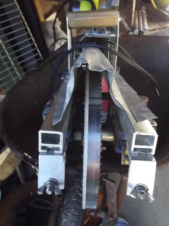 After the
first one the band was pretty dull, and I went
to change it. I put on a new 88 inch band, which was longer than the
previous. I had to loosen four bolts and move the band tensioners to
the very end of the rails, and the band/wheel also came almost to their
end. But it worked fine! It demonstrates the flexibility of the saw.
Most bandsaws can only use one specific length of band. 88 is about
the longest. The cut width can be opened to 16 inches. Since I've never
cut wider than 13, that seems like lots.
After the
first one the band was pretty dull, and I went
to change it. I put on a new 88 inch band, which was longer than the
previous. I had to loosen four bolts and move the band tensioners to
the very end of the rails, and the band/wheel also came almost to their
end. But it worked fine! It demonstrates the flexibility of the saw.
Most bandsaws can only use one specific length of band. 88 is about
the longest. The cut width can be opened to 16 inches. Since I've never
cut wider than 13, that seems like lots.
The 93 inch bands I used with the original rendition of
the saw had the right wheel protruding past the end. In the present one
the band alignment/tension adjuster would be off the end of the rails.
Of course, one could use Alaska mill rails longer than 36
inches. (and presumably make the top guard longer too.) The sky's the
limit if you think the saw will cut boards wide enough to need such
lengths.
When I took the guide
wheels off to change the band, one of them fell apart and the needle
fell out. It had cracked inside. I don't think much of the quality of
any of the small bearings I've bought. I thought these ones, made for
transporting a belt or something, would be better. Of course they are
spinning at high speed. Notwithstanding that they are all "sealed" and
"permanently greased", I've found oiling them before each use is a
really good idea. The thrust bearings keeping the band from moving
backward have been excellent - so far.
This sort of thing could become a real headache, a cause
of continuing complaints, if one was offering the saws as kits.
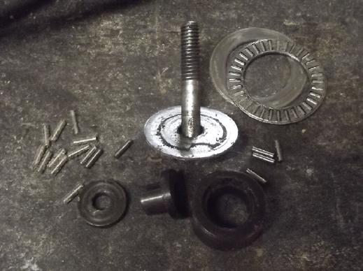
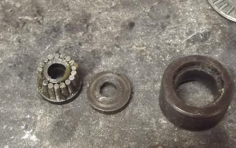 I greased the "bobbin" and stuck
the needles
back on. (Either there's an intended looseness or I just couldn't
I greased the "bobbin" and stuck
the needles
back on. (Either there's an intended looseness or I just couldn't
find one of them.) I put it together and held it closed until the bolt
was done up. Then it can't come apart...
until next time I change the band.
October's
Gardening
 I thought that
despite the several squashes I had planted I had had no result at all.
Just lots of vines. But one day I found one big squash in the tall
grass by the one really long vine. It mostly hadn't turned orange yet
near the end of October, but it was a squash!
I thought that
despite the several squashes I had planted I had had no result at all.
Just lots of vines. But one day I found one big squash in the tall
grass by the one really long vine. It mostly hadn't turned orange yet
near the end of October, but it was a squash!
 Raspberries, even on the last day of October! I think I like these
"everbearing" ones! Not that I'm picking them even once a week now and
the next pick may be the last. I
have a lot of raspberries in the freezer from July and August, from
picking all the bushes almost daily or every second day.
Raspberries, even on the last day of October! I think I like these
"everbearing" ones! Not that I'm picking them even once a week now and
the next pick may be the last. I
have a lot of raspberries in the freezer from July and August, from
picking all the bushes almost daily or every second day.
I still have potatos to dig
up. After not digging them up and losing most of the crop to the ground
freezing so hard last year, I'm storing them now in buckets of sand in
a cool dark place.
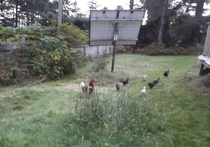 The chickens
are enthusiasticly helping scratch up the garden soil when I let them
out a while before dark.
The chickens
are enthusiasticly helping scratch up the garden soil when I let them
out a while before dark.
 I had been
getting seaweed for fertilizer - just gathering it in a bucket when I
would go for a walk. It's hard to get a lot that way, but I don't want
to buy and license a quad to drive on the beach just to get collect it.
There is often a
lot of eelgrass, which takes ages to decompose. In September or October
a lot of kelp washed in. I snapped off chunks of it and put them in the
bucket.
I might have got in 2 or 3 kelp stalks.
I had been
getting seaweed for fertilizer - just gathering it in a bucket when I
would go for a walk. It's hard to get a lot that way, but I don't want
to buy and license a quad to drive on the beach just to get collect it.
There is often a
lot of eelgrass, which takes ages to decompose. In September or October
a lot of kelp washed in. I snapped off chunks of it and put them in the
bucket.
I might have got in 2 or 3 kelp stalks.
In late October I (finally) went to get more seaweed and
found a kelp bulb. But by now it was too dried out. It only bent
instead of breaking. Then I realized I could curl the whole thing into
the bucket. Then I realized there was more. Much had washed up above
the regular tide lines in a storm. Some was so dried out it just looked
like strings and I wouldn't have noticed it.
I thought that the fertilizer value of dried kelp is
probably almost as good as wet, and it had really shrunk up and
lightened. I gathered up all the kelp around that spot. It either
fit in the bucket or I dragged it along in my other hand like pieces of
rope. It was still pretty light. Instead of 2 or 3 kelps, I had 20 or
30! It seems to me it must be quite concentrated now, and I collected
from a couple more sections of beach in the next couple of days. If
would have taken me weeks of walks to get that many kelps when it was
fresh!
Between chicken leavings, kelp and other seaweed, I should
have some pretty fertile soil by spring.
Electricity
Storage
(No Reports)
Electricity
Generation
My Solar Power System
The Usual Daily/Monthly/Yearly Log of Solar
Power Generated [and grid power consumed]
(All times are in PST: clock 48 minutes ahead of local sun time, not
PDT which
is an hour and 48 minutes ahead. (DC) battery system power output
readings are reset to zero
daily (often just for LED lights, occasionally used with other loads:
Chevy Sprint electric car, inverters in power outages or other 36V
loads), while the
grid tied readings are cumulative.)
Daily Figures
Notes: House Main
meter (6 digits) accumulates. DC meter now
accumulates until [before] it loses precision (9.999 WH => 0010
KWH), then is
reset. House East and Cabin meters (4
digits) are reset to 0 when they get near 99.99 (which goes to "100.0")
- owing to loss of second decimal precision.
Km = Nissan Leaf electric car drove distance, then car was charged.
New Order of Daily Solar Readings (Beginning May 2022):
Date House, House, House, Cabin => Total KWH Solar [Notable
power
Uses (EV); Grid power meter@time] Sky/weather
Main
DC East
September
30th 715.79, 7.20, 52.05, 45.16 => 7.13 [50Km;
9515@19:00]
October
1st 718.37, 7.27, 53.95, 46.65 => 6.04 [75Km; 9566@19:00]
2d 722.02, 7.37, 56.38, 48.76 => 8.29 [60 Km; 9604@21:30]
3rd 725.02, 7.45, 58.52, 50.51 => 6.37 [9626@19:00]
4th 726.53, 7.52, 59.06, 51.31 => 2.92 [9676@20:00] --
I think there's something funny with the carport system.
5th 730.20, 7.55, 60.63, 53.27 => 7.23 [45Km; 9716@18:30]
6th 731.64, 7.58, 61.11, 54.06 => 2.64 [55Km; 9754@22:00]
7th 735.36, 7.62, 62.58, 56.01 => 7.18 [45Km; 9784@18:00]
8th 735.78, 7.65, 62.72, 56.30 => 0.88 [75Km; 9817@18:30] WOW!
9th 737.77, 8.07, 62.82, 57.48 => 3.69 [9833@19:00] (1.) Checked
carport system. The new grid tie on the two collectors on the pole was
red light only. It's only a few months old, but seems to have quit!
(2.) Now that the wasps are [long] gone, I mounted the ground fault
receptacle on the carport wall. I tripped the "test" button with the
power out and found I couldn't reset it. I forgot about it when the
power came back, so virtually no power from carport system today. (3.)
3 hour power fail 10-13:00 -- exactly when the sun was shining.
(probably wild storm last night brought down some trees.) (4.) I ran
the fridge and freezers off the 36V system with an inverter while the
power was out. With the power off there was lots of power for the DC
system, but it wasn't recharging the battery as fast it was being
drained, 100W versus 200W. I replaced the #14 AWG cable to the Sprint
car (with the battery) with #10 wires, and it charged nearly twice as
fast. I should replace the other cable that this one plugs into, as
well. #14 cable can handle the current fine, but the voltage just needs
to drop a little before the charger sees 39.4V at its end ["charged"]
and reduces charging current, while it's actually (eg) 39.25V ["needs
some charging"] at the battery.
10th 738.22, 8.18, 62.98, 57.83 => 1.07 [55Km; 9868@18:30] Wut a dul
day!
11th 742.02, 8.23, 64.75, 60.26 => 8.05 [65Km; 9886@18:30] Brighter!
At end of day I changed two carport panels from one seemingly
non-working grid tie to the suspicious one. (The new one that quit was
only a few months old - yow!)
12th 742.93, 8.28, 65.04, 60.75 => 1.74 [9908@18:00; 2 dryer loads]
Storm &
wind but little rain.
13rd 745.33, 8.31, 66.01, 62.16 => 4.81 [90Km; 9949@22:00] Calmer
AM, then storm again later. End of day: swapped 2 panels to good grid
tie, just one on 'suspicious' tie (which seems to work occasionally).
(13rd = "teeny-third" - see "Scattered Thoughts")
14th 748.36, 8.36, 67.75, 63.98 => 8.46 [55Km; 9979@22:00; 50Km]
("teeny fourth")
15th 751.67, 8.39, 69.48, 65.77 => 6.86 [9990@17:30] ("teeny fifth",
etc.)
16th 755.24, 8.46, 71.67, 67.36 => 7.42 [10006@18:00] Some sun today!
17th 756.28, 8.52, 72.22, 67.91 => 2.20 [10022@18:30; 60Km] Cloudy,
windy, wet, dark, cold.
18th 759.10, 8.84, 74.48, 69.52 => 7.01 [10048@17:30] Pretty nice
for being outside, esp. after yesterday.
19th 762.69, 9.05, 76.89, 71.75 => 8.44 [10064@18:00] Nice in the
sun, otherwise rather cold. Must be October! ("teeny ninth")
20th 766.31, 9.15, 79.28, 74.33 => 8.67 [90Km; 10093@18:00] Lovely
day again!
21st 769.00, 9.31, 81.39, 76.20 => 6.73 [55Km; 10110@20:00] Nice
again?!?
22d 773.98, 9.37, 84.85, 79.25=>11.55 [10136@17:30] Sunny all
day but cold anyway!
23rd 777.07, 9.52, 87.21, 81.71 => 8.06 [10159@18:00] Frost in AM.
Started sunny, clouded over later.
24th 781.92, 9.55, 90.26, 84.19=>10.41 [10177@18:00] Sunny, but cold
like winter!
25th 787.49, 9.59, 93.76, 87.72=>12.64 [60Km; 10208@23:30] same -
clear all day except spreading jet trails
26th 793.10, 9.63, 97.22, 91.23=>12.62 [10221@18:00] Clear again!
27th 798.28, 9.68, 2.99, 94.23=>11.22 [90Km;
10235@17:30] Frosty mornings, sunny days.
28th 802.68, 9.73, 5.60, 96.92 => 9.75 [145Km;
10296@22:30] Sunny except a LOT of obscuring jet trails.
29th 807.53, 9.79, 8.37, 2.88=>10.56 [10308@18:00]
Sunny AGAIN!
30th 808.74, 9.84, 8.98, 3.56 => 2.55 [10321@18:00]
Aaand it's gone - the sun that is.
31st 810.05, 9.90, 9.64, 4.35 => 2.82 [55Km;
10357@17:30]
November
1st 811.18, 9.97, 10.48, 5.23 => 2.92 [10378@17:30]
2d 812.88, .06, 11.09, 5.96 =>
3.10 [10399@18:00]
3rd 813.85, .14, 11.60, 6.56 => 2.16 [90Km; 10437@22:30]
Chart of daily KWH from solar panels.
(Compare October 2023
(left) with September 2023 & with October 2022.)
Days of
__ KWH
|
October 2023
(18 collectors)
|
September 2023
(18 collectors)
|
October 2022
(18 collectors)
|
0.xx
|
1
|
|
|
1.xx
|
2
|
|
1
|
2.xx
|
5
|
|
6
|
3.xx
|
1
|
1
|
2
|
4.xx
|
1
|
2
|
2
|
5.xx
|
|
2
|
4
|
6.xx
|
4
|
2
|
|
7.xx
|
4
|
2
|
2
|
8.xx
|
6
|
2
|
1
|
9.xx
|
1
|
3
|
2
|
10.xx
|
2
|
2
|
4
|
11.xx
|
2
|
4
|
1
|
12.xx
|
2
|
3
|
2
|
13.xx
|
|
1
|
1
|
14.xx
|
|
4
|
3
|
15.xx
|
|
|
|
16.xx
|
|
1
|
|
17.xx
|
|
|
|
Total KWH
for month
|
208.08
|
295.65
|
238.62 |
Km Driven
on Electricity
|
1272.8 Km
(170 KWH?)
(ODO: 101923)
|
1115.1 Km
(150 KWH?) |
1043.2 Km
(~143 KWH)? |
Things Noted - October 2023
* Like September, October 2022 was a lot nicer than most of this
October. Storms, clouds... And
single digit solar KWH's! But then a
week of a sunny but frosty cold days near the end of the month brought
the solar picture up over 200 KWH.
Monthly Summaries: Solar Generated KWH [& Power used from
grid KWH]
As these tables are getting long, I'm not repeating the log of monthly
reports. The reports for the first four full years (March 2019 to
February 2023) may be found in TE
News
#177,
February
2023.
2023 - (House roof, lawn + DC + Cabin + Carport, Pole) Solar
Jan KWH: 40.57 + 3.06 + 28.31 + 21.85 = 93.79 Solar [grid: 1163; car
(these are very rough estimates): 130]
Feb KWH: 59.19 + 2.70 + 38.10 + 32.47 = 132.46 Solar [grid: 1079; car:
110]
(Four years of solar!)
Mar KWH: 149.49 + 2.72 + 53.85 + 92.08 = 298.14 Solar
[grid: 981; car:
140]
Apr KWH: 176.57 + 2.71 + 121.21 + 108.34 = 408.83 [grid: 676; car: 160]
"Lawn" collectors moved to South
"Wall"
May KWH:266.04 + 2.04 + 194.13 + 180.31 = 642.52 [grid: 500; car: 175]
Jun KWH: 237.55 + 3.70 + 172.56 + 126.31 = 540.12 [grid: 464; car: 190]
July KWH:236.99 + 1.95 + 169.16 + 155.21 = 563.31 [grid: 343; car: 180]
Aug KWH:223.61 + 1.78 + 158.31 + 134.40 = 518.00 [grid: 305; car: 130]
Sep KWH:124.33 + 2.33 + 92.76 + 76.23 = 295.65 [grid:
501; car: 150]
Oct KWH: 94.26 + 2.70 + 55.01 + 56.11 =
208.08 [grid: 842; car: 170]
Annual Totals
1. March 2019-Feb. 2020: 2196.15 KWH Solar [used 7927 KWH
from grid]
2. March 2020-Feb. 2021: 2069.82 KWH Solar [used 11294 KWH from grid]
(More electric heat - BR, Trailer & Perry's RV)
3. March 2021-Feb. 2022: 2063.05 KWH Solar [used 10977 KWH from grid]
4a. March 2022-August 2022: in (the best) 6 months, about 2725 KWH
solar - more than in any previous entire year!
4. March2022-Feb. 2023: 3793.37 KWH Solar [used 12038 KWH from grid]
Money Saved or Earned - @ 12¢ [All BC residential elec.
rate] ; @
50¢ [2018 cost of diesel fuel to BC Hydro] ; @ 1$ per KWH [actual
total
cost to BC Hydro
in 2022 according to an employee]:
1. 263.42$ ; 1097.58$ ; 2196.15$
2. 248.38$ ; 1034.91$ ; 2069.82$
3. 247.57$ ; 1031.53$ ; 2063.05$
4. 455.20$ ; 1896.69$ ; 3793.37$
It can be seen that the benefit to the society as a whole
on Haida Gwaii from solar power installations is much greater than the
cost savings to the individual user of electricity, thanks to the heavy
subsidization of our power
owing to the BC government policy of having the same power rate across
the entire province regardless of the cost of production. And it can be
insurance: With some
extra equipment and a battery, sufficient solar can deliver essential
power in
electrical outages however long. (Feb 28th 2023: And it's probably well
over 1$/KWH by now the way inflation of diesel fuel and other costs is
running.)
http://www.TurquoiseEnergy.com
Haida Gwaii, BC Canada