Turquoise Energy News Report #186
Covering
November
2023 (Posted December 8th 2023)
Lawnhill BC Canada - by Craig Carmichael
[CraigXC at Post dot com]
www.TurquoiseEnergy.com
= www.ElectricCaik.com
= www.ElectricHubcap.com
Month In "Brief"
(Project Summaries etc.)
-
Miles Mini Cargo Van EV - "Everlasting" NiZn Battery Development - New
Air Compressor-Decompressor Design for Open Loop Air Heat Pumping -
Power Line Electric Fields - Cabin Construction & 40V("36V") DC
In
Passing
(Miscellaneous topics, editorial comments & opinionated rants)
- Jet Contrails or "Chemtrails" and Climate Chaos - Scattered
Thots (a better way to kill hair mites - ... - Strange Lunar Surface) -
ESD
- Detailed
Project Reports
-
Electric
Transport - Electric Hubcap Motor Systems
* Miles Truck - for now: Fixed
ratio Drive. Running, has too much vibration - Handheld Programmer
working... sort of.
Other "Green"
& Electric Equipment Projects
* Air Compressor-Decompressor Designs for Open Loop Air Heat
Pumping
("OLAHP") - & a great indoor heat radiator?
* Cabin Construction
* Shielding from Power Line Electric Fields
Electricity Storage:
Batteries
* New Build with Perforated Tube Plastic Pocket Electrodes - Charging
& Initial Tests - Problems
Electricity Generation
* My Solar Power System: - The Usual Latest Daily/Monthly
Solar Production log et cetera - Monthly/Annual Summaries,
Estimates, Notes
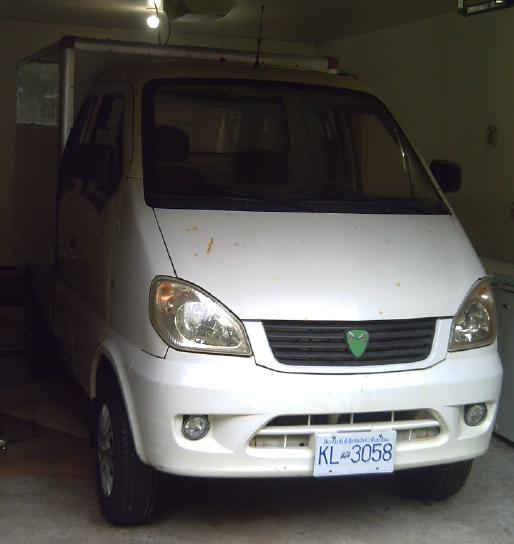
Miles Mini Cargo Van EV
 I
added some "vibration absorber" rubber pieces, cut from
the sidewall of an old tire with a sharp knife, to cushion the bolts
holding the 5 to 1
planetary gear body and the rear of the transmission housing. In theory
I should have put some rubber tubing between the bolts and the parts,
but that would have meant disassembling everything and making the holes
in the parts bigger to fit them. As it was I took off one bolt, added
the rubber "sandwich" pieces, put it back on and then did the other.
Simple. The result was a
cushioning of the vibration but not its
elimination.
I
added some "vibration absorber" rubber pieces, cut from
the sidewall of an old tire with a sharp knife, to cushion the bolts
holding the 5 to 1
planetary gear body and the rear of the transmission housing. In theory
I should have put some rubber tubing between the bolts and the parts,
but that would have meant disassembling everything and making the holes
in the parts bigger to fit them. As it was I took off one bolt, added
the rubber "sandwich" pieces, put it back on and then did the other.
Simple. The result was a
cushioning of the vibration but not its
elimination.
The drive shaft isn't perfectly centered. That's probably
the main source of vibration. I'll try clamping on a balancing weight
or two with pipe clamps.
I regret not having saved the original piece that slipped
into the front of the driveshaft. I hang on to so much. For once I
decided to "toss junk" (the original transmission) and really missed a
piece later.
I finally got the handheld
programmer to talk to the
truck's motor controller. The problem all along had been that a pin
would push a ways out the back of the four pin in-line Molex connector
when I
plugged the programmer in, instead of connecting. I don't have
replacement Molex pins, so I'll just have to be careful to push the pin
back in each time I plug in the programmer.
However, I was unable to change anything. The RPM wouldn't
go above a low 3840 RPM (the Curtis AC34 motor can do 10,000; 5000
continuous). Other things I changed didn't seem to make any difference
to the operation. With the increased reduction ratio, it has sudden,
almost violent acceleration, "emergency stop" regen braking when the
foot is lifted from the "gas" pedal, and one must almost stand on the
brake to stop it from clawing its way forward or back.
Now what?
"Everlasting" NiZn Battery Development
 I
thought I had solved all the chemistry problems last winter, and after
a busy summer I got back to it. Seeing all the lithium battery fires
lately a type that won't easily burn or explode seems even more
worthwhile.
I
thought I had solved all the chemistry problems last winter, and after
a busy summer I got back to it. Seeing all the lithium battery fires
lately a type that won't easily burn or explode seems even more
worthwhile.
Since I couldn't seem to make
a flat cell that didn't start leaking, I had decided to try
3D printing "perforated plastic pocket electrode tubes" and place them
in "any
old [unpressurized] container". I designed them and printed some
samples in PLA. I
couldn't believe the tall, thin shapes wouldn't come loose during
printing, so I printed 30mm and 67mm tall versions before going for the
full 100mm.
 Then I printed
four in PVB, soaked some art paper in toluene and (when dry) rolled it
up inside, made some
Ovonics mix positive electrode mix with acetone, some zinc mix with dry
cell zinc, zinc flakes and zircon, and stuffed three electrodes. The
two positives had cupro-nickel sheet current collectors and the zinc
had #14 AWG copper wire.
Then I printed
four in PVB, soaked some art paper in toluene and (when dry) rolled it
up inside, made some
Ovonics mix positive electrode mix with acetone, some zinc mix with dry
cell zinc, zinc flakes and zircon, and stuffed three electrodes. The
two positives had cupro-nickel sheet current collectors and the zinc
had #14 AWG copper wire.
 I put them into a small bottle filled with 10% potassium chloride salt
solution for electrolyte. pH was about 12, a little lower than with
more concentrated solution. I charged it for a few
hours. Whatever current it put out into a load, low current or high, it
did so without voltage fade over minutes. Looks like it holds
"amp-hours" instead of "milliamp minutes"! This I attribute to the
acetone technique.
I put them into a small bottle filled with 10% potassium chloride salt
solution for electrolyte. pH was about 12, a little lower than with
more concentrated solution. I charged it for a few
hours. Whatever current it put out into a load, low current or high, it
did so without voltage fade over minutes. Looks like it holds
"amp-hours" instead of "milliamp minutes"! This I attribute to the
acetone technique.
But however much it was charged the voltage didn't hold
above
around 1.3 volts instead of 1.8 to 2. After three days the cupro-nickel
terminals had corroded off at the waterline. Perhaps the corrosion was
happening at the 1.3 volt level?
It seems that various current collectors I've tried work
fine
inside the electrode but corrode around the waterline where they come
out of the cell. My zinc terminals all did that. In this cell the
copper wire
on the zinc side seems okay.
I guess I'll have to use some form of graphite for the
positive terminals & current collector. Maybe before Christmas I
can manage to poke some graphite foil or something into the two
existing electrodes and maybe make a third with a graphite rod in it.
(There are more developments for the December report...)
New Air Compressor-Decompressor Design for Open Loop Air Heat
Pumping (OLAHP)
 With a simple air compressor using just the heat from the compressed
air, one loses ~29% of the energy used when the compressed air exits
the system. With a compressor-decompressor one uses the heat and then
the cooled but still compressed air is fed back into the unit and in
decompressing helps drive it to compress the next cylinder full. This
is part of what's needed to get high COP [Coefficient Of Performance]
in air heat pumping.
With a simple air compressor using just the heat from the compressed
air, one loses ~29% of the energy used when the compressed air exits
the system. With a compressor-decompressor one uses the heat and then
the cooled but still compressed air is fed back into the unit and in
decompressing helps drive it to compress the next cylinder full. This
is part of what's needed to get high COP [Coefficient Of Performance]
in air heat pumping.
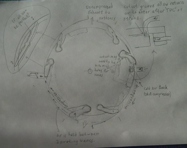
In the middle of an inexplicably sleepless night I thought
up a rotary air compressor with pivoting vanes pushing air into a
decreasing volume with a non-concentric outer wall. The
pivoting vanes would be held out [sealed] by centrifugal force and the
air pressure. That should solve a lot of the mechanical difficulties of
sliding ones.
But to both compress and decompress, it needed to have
vanes facing both directions, and later I drew an "expansion" side.
 The 1970s
ROVAC design with a round rotor in an elliptical outer cylinder with
sliding vanes looked good in theory, but was complex and probably had
too much friction from the vanes to be practical. AFAIK it was never
produced.
The 1970s
ROVAC design with a round rotor in an elliptical outer cylinder with
sliding vanes looked good in theory, but was complex and probably had
too much friction from the vanes to be practical. AFAIK it was never
produced.
I noticed that my second drawing looked rather like a
"ROVACS" unit but with the pivoting vanes and fewer of them.
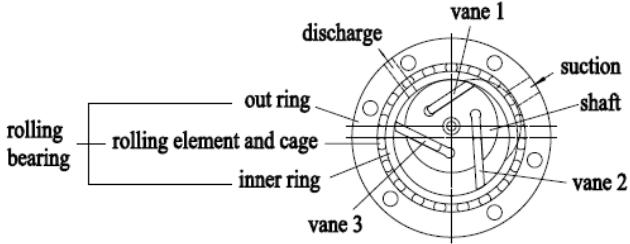 Then I saw a newer design ("HEVC") with a circular rotor in an
off-center circular cylinder, which had fewer sliding vanes but was
only a compressor. (I neglected to copy the URL.) There was some
complicated stuff to reduce vane friction. I'll try alume vanes sliding
on UHMW polyethylene, which is as slippery as teflon. The circular
outer cylinder seems simpler so that's what I plan to build, with the
pivoting vanes of course.
Then I saw a newer design ("HEVC") with a circular rotor in an
off-center circular cylinder, which had fewer sliding vanes but was
only a compressor. (I neglected to copy the URL.) There was some
complicated stuff to reduce vane friction. I'll try alume vanes sliding
on UHMW polyethylene, which is as slippery as teflon. The circular
outer cylinder seems simpler so that's what I plan to build, with the
pivoting vanes of course.
That's if I ever manage to get to the project. I do have
incentives: needing to cut/haul/split/stack less winter firewood and
shrinking my winter electric bill or even running the heater off solar
power.
(There's another development on this for
the December report.)
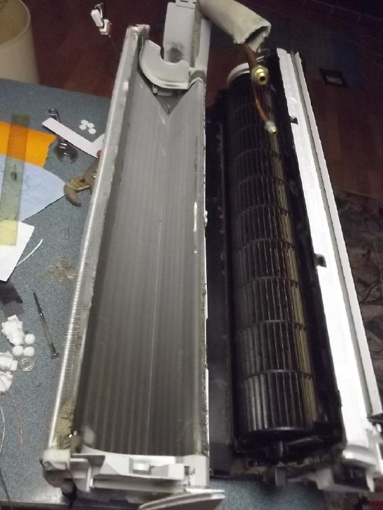 Perry is now installing, repairing and cleaning [refrigerant based]
heat pumps. I asked him about the indoor radiators and he gave me a
"junk" one. I took it apart and decided it looks almost ideal. I think
it should work just as well with compressed air, although it may be
necessary to reduce the airflow/heating capacity more than desired
owing to its tiny pipe sizes. So, that's one of the three components I
don't have to make myself! (...except I need to get the five-wire, high
voltage motor to run without the logic board that usually drives it.
The unit was a discard because the board was bad.)
Perry is now installing, repairing and cleaning [refrigerant based]
heat pumps. I asked him about the indoor radiators and he gave me a
"junk" one. I took it apart and decided it looks almost ideal. I think
it should work just as well with compressed air, although it may be
necessary to reduce the airflow/heating capacity more than desired
owing to its tiny pipe sizes. So, that's one of the three components I
don't have to make myself! (...except I need to get the five-wire, high
voltage motor to run without the logic board that usually drives it.
The unit was a discard because the board was bad.)
The indoor-outdoor heat
exchanger I can do. The better I make it, the better the system
performance will be. Making the pivoting vane air
compressor-decompressor will be the major challenge.
More details and a "recap" of how
the OLAHP system works are to obtain much higher COP's than refrigerant
based systems are in the detailed report.
Power Line Electric Fields
Apparently power lines and AC power fields are less benign
than most of us blithely assume. Not only do they seem to be the
probable cause of "everlasting" tinnitus (through some obsure path
whose mechanism some day will doubtless be known), but evidently
children are
four times as likely to develop leukemia in homes with higher fields,
and it even depends where their bed is situated WRT outlets or
electrical equipment wiring.
I found this at this web site with information about power line
electric fields
as related to other aspects of health (not tinnitus).
https://magneticsciences.com/EMF-health/
There are two measures: milligauss magnetic field and
volts per meter of electrical gradient. The magnetic component depends
how much current is flowing in the lines. Even without a meter, one may
estimate the "volts per meter". If the power lines are 10 meters high
and the line on top is 14,400 volts, the gradient through the air to
the zero volts ground underneath is 1440 volts per meter (RMS). The
farther one is from the lines, the lower the gradient. I suspect that
it is this gradient that is related to tinnitus rather than the
magnetic aspect. In that case a powered AC line with no load is just as
bad as one driving a heavy appliance. But I could easily be wrong or
possibly
both fields play a part.
As I started to realize that a big metal roof grounded
only in one corner is probably just a big antenna for such fields and
that I should ground all four corners of my cabin (and maybe in the
middle of the walls too!), I soon realized that the house should be
treated the same way, and that with the power poles so close I might
cut the intense blast of my tinnitus even while spending most of my
time in the house, by placing several grounding rods around the
perimeter, each connected to the metal roof. The more ground points,
the more it's like being underground instead of exposed.
I had imagined or wishfully thought, without checking,
that the southeast
corner of the main roof would be grounded where the electrical service
pipe came through it. In fact it was deliberately isolated with a
rubber gasket. None of the five roof sections of the house was
grounded at all.
So on the 15th I started grounding the house roof
sections, pounding 3 foot copper pipes into the dirt and connecting
wires from them to under the metal roofing where a screw was, removing
the screw so I could pry it up a bit. I usually managed just one ground
point a day but in some places grounding two adjacent roof sections. I
kept at it when the weather was okay. 1. SW corner of main roof &
SE corner of shop roof. 2. NW corner of main roof & NE corner of
shop roof. 3. S center of main roof 4. SE corner of main roof & SW
corner of kitchen roof. 5. S center of kitchen roof.
I'm starting to notice more when my tinnitus seems
louder than usual. After grounding the south-center of the kitchen roof
closest
to the power poles - up a ladder in that 1000-1440 volts per meter
gradient
- my tinnitus was screaming. By the next morning I conceived that the
ringing was a little less strident than usual, with more variableness,
as I had felt during my head shielding experiments a couple of months
ago. But then it seemed to be getting worse again as I wrote this.
Well! sitting at my computer writing I can see the power lines out the
unshielded bay window. How can I expect improvement? I went right out
and put [2" mesh] chicken wire up over the window.
It was also worse after cutting firewood by the highway
for some hours. That was again right under the power lines, and also
with a very loud chainsaw that I must have run for 1/2 an hour or more
all told.
On a day that I drove into town twice - two hours on the
highway right under the power lines, and in the Toyota Echo (with
an amateur muffler repair somewhat noisy) - it seemed worse, and still
worse the next morning 15 hours later. Now with some grounding of the
house, not venturing out on the highway for 2 or 3 days seems to quiet
it a bit. a bit.
Cabin Construction & 40 V DC Electrical Wiring
The cabin has to an extent turned into an experiment to
prove (or otherwise) that "everlasting" tinnitus is caused by AC
electric power fields. With metal sides and roof and wire screening
over the windows, grounded at multiple points, it is becoming a "Farady
Cage" to keep fields out. Inside, I'm wiring it with 36 volts (or call
it 40 volts) DC, the highest voltage that's generally safe to touch and
being DC lacking any AC oscillating fields. When it's ready and I can
spend much of my time in it for a few days, I fully expect the
ever-present ringing in my ears will diminish to a point where I can
definitively say "it works", even without being able to measure dB
levels inside my ears and head.
Originally I had planned to wire it up with 120 VAC like
most buildings. Now instead there's one AC sub panel with one breaker
(total overkill!) and just one duplex AC outlet just above it in one
corner, just plugged into the house with a long extension cord, for
connecting the solar grid ties and anything I really need AC for - at
the moment, power tools. I bought lots of house wire, and three more
spools at a garage sale. All just as good for DC wiring as AC.
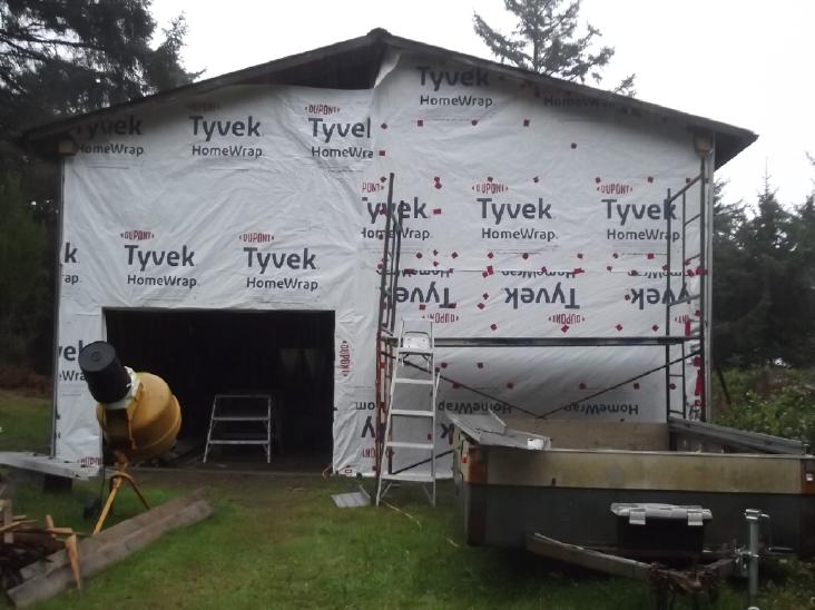 The days became short, headed for winter solstice. On the
1st and 2nd I put up the remaining plywood and then "tyvek" on the last
outside wall section, leaving just the garage door and a couple of
windows with no glass in them yet. Seems I was just in time. It had
been quite dry, but rainy winter weather began that evening.
"Indian summer" was over. But now I could continue the inside work
during
bad weather.
The days became short, headed for winter solstice. On the
1st and 2nd I put up the remaining plywood and then "tyvek" on the last
outside wall section, leaving just the garage door and a couple of
windows with no glass in them yet. Seems I was just in time. It had
been quite dry, but rainy winter weather began that evening.
"Indian summer" was over. But now I could continue the inside work
during
bad weather.
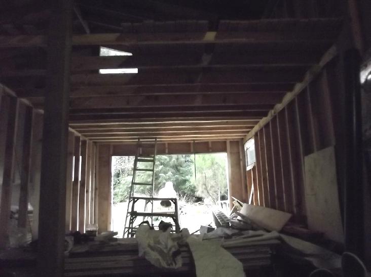 I framed the
inside wall of the garage area, then the
ceiling/upstairs floor joists over it. I used doubled-up 2 by 4's in
the area the roll-up garage door needed space above. That lowered the
floor and increased the headspace upstairs by 2 inches over using 2 by
6's. I used 2 by 6's notched at the ends
for the rest.
I framed the
inside wall of the garage area, then the
ceiling/upstairs floor joists over it. I used doubled-up 2 by 4's in
the area the roll-up garage door needed space above. That lowered the
floor and increased the headspace upstairs by 2 inches over using 2 by
6's. I used 2 by 6's notched at the ends
for the rest.
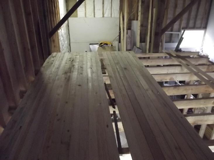 I bought and
glued on some tongue and
groove flooring. After a dozen boards I thought I should wait until
they were dry so cracks wouldn't open up when they shrink. To have
enough I brought two batches of 24 T & G boards on roofracks on the
Echo. One of the racks bent.
I bought and
glued on some tongue and
groove flooring. After a dozen boards I thought I should wait until
they were dry so cracks wouldn't open up when they shrink. To have
enough I brought two batches of 24 T & G boards on roofracks on the
Echo. One of the racks bent.
Home Depot in Prince George resold the garage door
I had bought before it could be delivered to me. (Thanks a lot!) Now
they're twice the price. I ran
across some never installed galvanized furnace ducts, discarded at
the refuse
station. I took some and came up with an idea for a fan-fold garage
door made of 2 inch extruded styrene foam core with a metal
outside face and epoxied polypropylene inside.
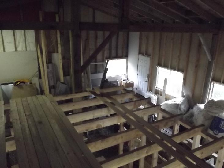 Indoor View from 2nd floor
(Clutter, clutter -
ug!)
Indoor View from 2nd floor
(Clutter, clutter -
ug!)
Hmm, I could get rid of some of that ceiling insulation by putting it
in the ceiling.
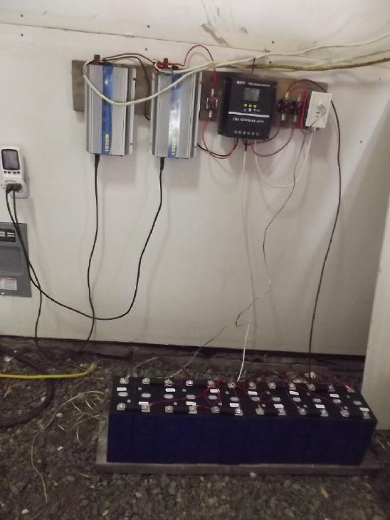 My LiFePO4 batteries had arrived, and I set up the 40 ("36")
volt DC electrical system temporarily with the battery on the gravel
floor. Not only did I want to try it all out, but I wanted lights.
My LiFePO4 batteries had arrived, and I set up the 40 ("36")
volt DC electrical system temporarily with the battery on the gravel
floor. Not only did I want to try it all out, but I wanted lights.
The charge controller, a new type on AliExpress.com, is
passable. At least it's a new option for 36 volts.
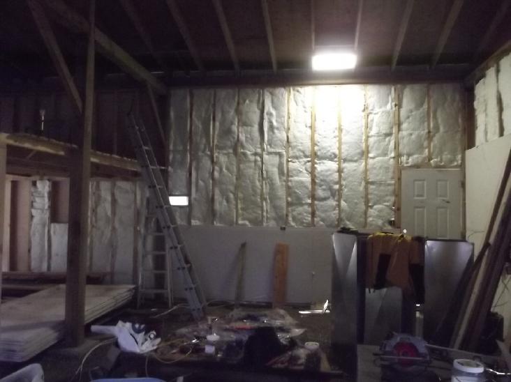 Now I have
a 40V panel light in the ceiling in the darkest corner with a
light switch by the door, recharged by the sun.
Now I have
a 40V panel light in the ceiling in the darkest corner with a
light switch by the door, recharged by the sun.
I also plugged
in a lamp and made a long extension cord to use it upstairs or wherever.
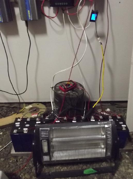 Just to try it, I unscrewed the 12-60V DC LED light "bulb" and put in a
250W (@120V) incandescent heat bulb. At 40V it put out about 53W - not
much more than a hand warmer. Later I plugged in a
1500W electric resistance heater (one with radiant coils, no fan or
electronics) and
had a 40V, ~150W heater (4 amps). The elements don't quite glow even in
the dark, but it doesn't buzz because it's running on DC, and I can
feel the heat. Might be enough for a small room if
it's not too cold out, but running on batteries one might want it on a
timer - one can see the millivolts dropping with the minutes with the
heavy load on the batteries. (Need DC timer!)
Just to try it, I unscrewed the 12-60V DC LED light "bulb" and put in a
250W (@120V) incandescent heat bulb. At 40V it put out about 53W - not
much more than a hand warmer. Later I plugged in a
1500W electric resistance heater (one with radiant coils, no fan or
electronics) and
had a 40V, ~150W heater (4 amps). The elements don't quite glow even in
the dark, but it doesn't buzz because it's running on DC, and I can
feel the heat. Might be enough for a small room if
it's not too cold out, but running on batteries one might want it on a
timer - one can see the millivolts dropping with the minutes with the
heavy load on the batteries. (Need DC timer!)
It's an incentive to try
and get the open loop
air heat pumping working, to get 1500 watts of heating power
from that same 150W of electricity.
I have lots of smaller
gauge house wire. After thinking about it, I
decided to run two cables of "#14-3" AWG to wall outlets intended to be
capable of heavy loads, of which I had placed one where I thought I
just might have a countertop. "AWG" doubles in cross
section with each three of its reverse-numbered gauges, and "3 wires"
also has a fourth bare wire for "ground". So if one puts all the wires
in the cable together: two #14 together makes #11. Two #11 together
makes #8. So with one four-wire cable for "+" and another for "-" make
a #8 AWG equivalent. #8 is
rated for 40 amps continuous - about 1500 watts.
I took the gyproc off the wall and rewired the outlet with
the two "#14-3", then
put the gyproc back on. This is why I like screws rather than nails.
 A day or two
later I finished insulating that wall section, and started the next one
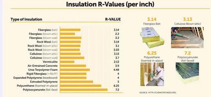
with the leftover pieces in the bag. That's three bags of (yetch!)
fiberglass insulation in
the walls, about 10 bags to go. For the walls. (Lower cost, friendly,
arguably higher
"R" value and (surprisingly) more fire resistant cellulose fiber
insulation is
simply not available in northern BC. Nor are cellulose and other
organic fiber insulation batts
that are available
in Europe to be had in North America.)
A day or two
later I finished insulating that wall section, and started the next one
with the leftover pieces in the bag. That's three bags of (yetch!)
fiberglass insulation in
the walls, about 10 bags to go. For the walls. (Lower cost, friendly,
arguably higher
"R" value and (surprisingly) more fire resistant cellulose fiber
insulation is
simply not available in northern BC. Nor are cellulose and other
organic fiber insulation batts
that are available
in Europe to be had in North America.)
Firewood!
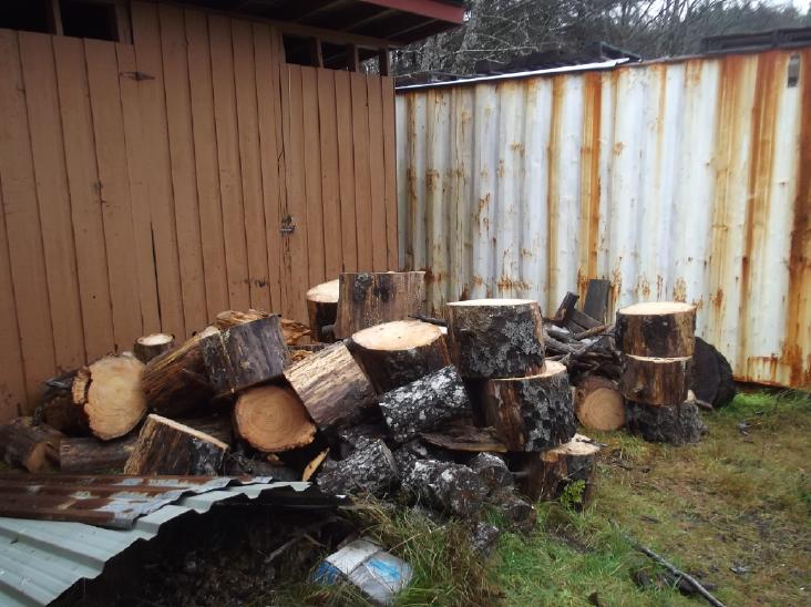 On Wednesday the 22nd, I
went to drive into town. I hadn't been
anywhere since Saturday. As I got to the end of my driveway I found
that a big standing dead tree had blown down, and someone had cut it
into sections and shoved them aside
because it was blocking the highway. That must have been what made the
power flicker during the storm on Monday - the branches hitting the
14,400
volt line - but not bringing it down! There were big chunks on both
sides of the road. How could I resist such a source of dry firewood
right outside
my own driveway? I was lucky no one had already taken it.
On Wednesday the 22nd, I
went to drive into town. I hadn't been
anywhere since Saturday. As I got to the end of my driveway I found
that a big standing dead tree had blown down, and someone had cut it
into sections and shoved them aside
because it was blocking the highway. That must have been what made the
power flicker during the storm on Monday - the branches hitting the
14,400
volt line - but not bringing it down! There were big chunks on both
sides of the road. How could I resist such a source of dry firewood
right outside
my own driveway? I was lucky no one had already taken it.
The lawn tractor wouldn't start. (Must charge the LiFePO4
battery - the tractor's charging system doesn't seem to.) I took the
small chainsaw down in the Leaf and started cutting on the inland side.
When I got to the ocean side of the highway, the trunk was large and I
used the big saw that I got for ripping slabs for lumber. I spent three
or four hours at
it until it was getting dark. Next morning was the last and largest
section. I could hardly lift the pieces into the car, so I started
cutting them just a foot long. I could only fit a few pieces in the
back
at a time, so I made quite a lot of very short trips. It looks like a
good portion of a firewood shed full.
By the time I had finished I had driven just 2.0 Km and
used 9% of the Leaf's battery power. (Firewood is heavy and my driveway
is uphill?) I'm glad it gets much better mileage than that in most
situations! (Mileage to town was also poor. It turned out that the
front left brake had started sticking "on".) The bottom 9' or so of the
tree was still standing. I'll cut it but I was worn out, my
tennis/tendonitis elbow was hurting and I felt a twinge in my back
lifting one of the last pieces into the car. And so much for tinnitus
mitigation, working with a very loud chainsaw on the highway right
under the power lines. Hearing protectors are no match for that saw and
useless for power lines. My ears, which had seemed a bit improved with
the house groundings, were ringing fiercely again when it was quiet on
the second evening.
Finish it later! Does "later" every come? I'm
starting to really hate leaving ends of jobs until
"later"! My dad was around my age when he said he had sold his big
chainsaw because he couldn't lift it any more. Well, I'm doing better
than that!
Gardening
Not much to say about gardening in the north in November.
Except the "everbearing" raspberry bushes were still making berries
well into the month, and a few things under LED lights indoors were
doing well.
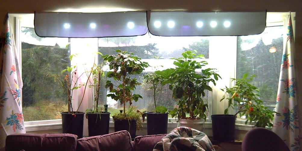 The Livingroom Window with 2+
years old plants.
The rightmost orange pepper is still producing well
The Livingroom Window with 2+
years old plants.
The rightmost orange pepper is still producing well
and the leafy coffee tree has about 50 unripe beans on it. (The coffee
tree on the left got "fried"
on a sunny day in my window greenhouse, which I have stopped using for
that reason.) Two sweet
red peppers and a tomato aren't doing well, but the one in the middle
now had some flowers.
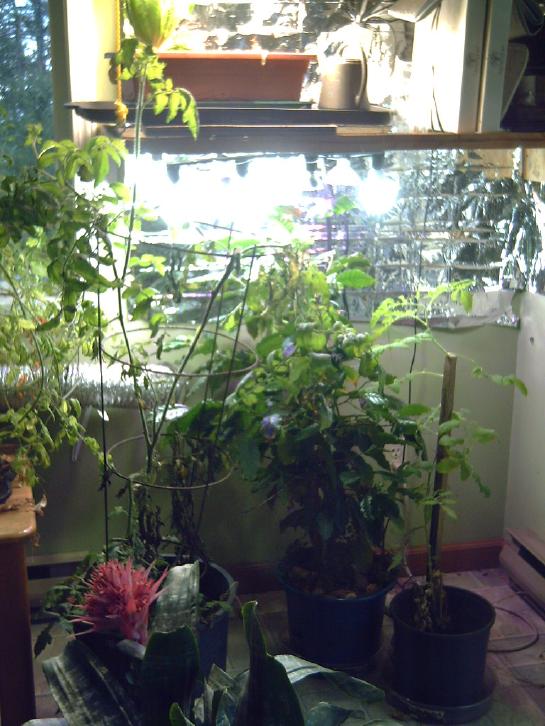 In the kitchen, some other
plants. A two-year
cherry tomato (far left) is still producing,
In the kitchen, some other
plants. A two-year
cherry tomato (far left) is still producing,
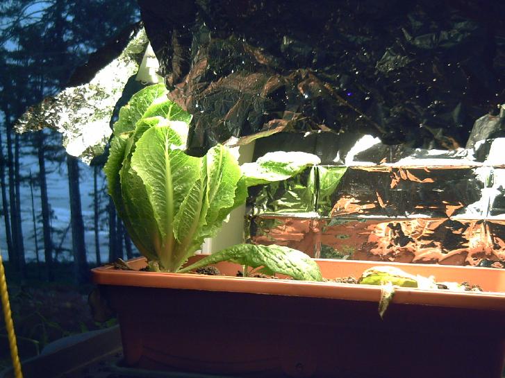
and one lettuce plant started in September remains from a pot of three
on the upper
shelf under a strong flat-panel LED grow light. (I should cut it and
start a new batch.)
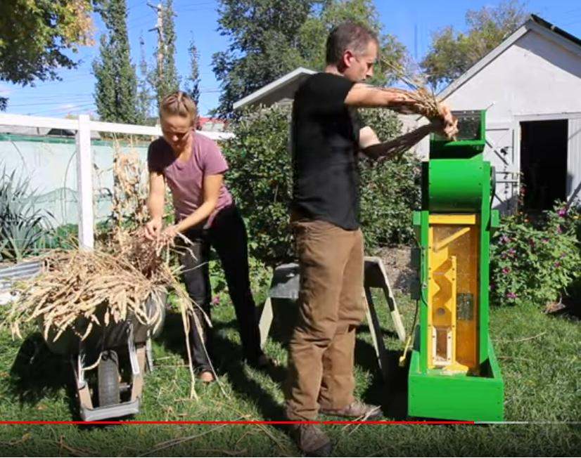 On youtube I
found a guy who had made this cool backyard machine for threshing and
winnowing wheat. Just the thing (along with a small flour grinder) to
make growing small patches of grain at least somewhat practical?
On youtube I
found a guy who had made this cool backyard machine for threshing and
winnowing wheat. Just the thing (along with a small flour grinder) to
make growing small patches of grain at least somewhat practical?
There were further and other ideas in the comments,
including just beating the wheat onto a screen over a bin (tote?) for
threshing, and making the winnowing machine separate. (Winnowing
basicly works by blowing: the heavier seeds go on down and the lighter
chaff is blown away sideways.)
Small Scale Grain Threshing Machine
https://www.youtube.com/watch?v=HsILv0_U3z0&ab_channel=VegetableAcademy
In
Passing
(Miscellaneous topics, editorial comments & opinionated rants)
Jet Contrails or "Chemtrails" and Climate Chaos
I watched a video of someone talking about the long
persisting contrails made by jet aircraft in recent times, which have
become ubiquitous
throughout the sky seemingly almost the world over. He explained that
"soot" in
the fuel created condensation particles, nuclei that water would
attract to and grow into droplets and then ice crystals. It was all
perfectly natural and normal, he said.
https://www.youtube.com/watch?v=edk-Up0v7JI&ab_channel=MentourNow%21
Everyone has noticed that a cloudy night is warmer than a
clear night. He stated that we "would be surprised" to learn that water
vapor is a much worse "greenhouse gas" than CO2, and that jet trail
clouds reflecting heat rays back to the earth account for 35 to 40
percent of jets' contribution to global
warming, adding to their carbon dioxide emissions. I was surprised,
first to finally hear someone besides me speak of thit and validate the
basis for my weather disruption theories, and second that (according to
him) it was only 40%.
But the presenter didn't look at the "side effects" of
this
atmospheric blanketing and heat retention way up in the stratosphere
where the air is normally very cold and thin clouds are
normally rather rare: (a) the disruption of global winds including the
jet streams owing
to the reduction of their main impetus, which is warm air rising into
air that's
colder and colder with altitude, and (b) the atmosphere holding much
moisture up
to such altitudes, also owing to the warmed air column, making for
droughts, "rivers from the sky" floods, record snowstorms and giant
hail. (c) Increased altitude and speed of some wind patterns, now
occurring in very thin air above the blanketing layer. These factors
rather than global warming would seem to account nicely for most of the
weather anomalies and cataclysms we have actually been seeing in recent
years.
As to the whole thing being a natural product of jet
travel, the issue is not clear cut to me. In years past, one would
often see contrails behind jets, but they were just a thin white line
that would
would disappear within tens of seconds, minutes at most. They never
spread out and out and out, blew
around with the wind and filled the sky.
The first time I saw persisting trails was probably in the
1990's or about 2000. Sitting on my porch I saw a long thin cloud drift
over. Then another, then another, a bunch of lines parallel to each
other over maybe half an hour. I thought to myself "I didn't know
clouds could form like that." I thought it was some strange
microclimate effect to do with odd winds and the mountains to the west.
It didn't happen again for many years.
And I recall that in the summers 2012 and 2013 I would
charge the Mazda RX7-EV from about 500 watts of available solar power
from the
four solar panels I had on my roof at that time. Up until then I rarely
observed or heard jet traffic over Victoria BC. In 2014 (I think it was
- or
else 2015) the whole picture was transformed. Every time one looked up
there was a jet, and long lasting trails were spread through the sky,
sometimes even creating a complete thin overcast.
And I could never again charge the RX7 from the solar
panels. Every time I tried, I would start it up and within about 10
minutes the inverter would start alarming that it didn't have enough
power. I would look outside and some very thin, inconspicuous high
cloud left by a jet would have got in front of the sun. After it
passed, at first I would try again. But again the alarm would soon go
off. I finally gave up. I was never again able to charge the car from
solar.
Why did Victoria suddenly go from "not under any common
jet route" to ubiquitous jet air traffic, all in one year? Or could
there have been more jets over Victoria than I ever noticed, but never
leaving
trails until 2014? Why from the East shore of Victoria would I hear the
rumble of heavy
jets taking off seemingly from the nearby US air base on Whidby Island
every few minutes? (or could I really be hearing jets taking off from
Seattle or Vancouver airport from such distances?) And why are there so
many jets over Haida Gwaii, BC too? Checking the globe with a string
for potential flight routes that would pass over Haida Gwaii... How
many hourly flights are there from Calgary to Tokyo, Calgary to
Anchorage or Seattle to Seoul? Vancouver to Pyongyang?
As for the makeup of the chemicals, I'm willing to
believe that it is soot in the fuel, composed of the chemicals people
have been finding on the ground and blaming on "chemtrails", esp. alume
oxide
and sulfates. But why in recent years is there so much soot in the jet
fuel that it is doing these things? Why has it become so dirty? The
video
presenter said it would cost a bit more to better refine the fuel to
reduce or prevent the trails. But in the past it must have better
refined. Why did it so suddenly get so dirty? And why do contrails
sometimes seem to switch on and off along the route as the jet flies?
(I suppose that could
be atmospheric conditions - ?)
There was a documentary from 2001 or so talking about
the possibilities for climate engineering. (I saw it on youtube, but it
was soon after
deleted.) It mentioned volcanic dust blocked sunlight and lowered
temperatures, and it brought up the idea of blanketing the atmosphere
with ??? high up to reflect sunlight. It was mentioned that this might
produce droughts.
Here my total speculation is that perhaps some petroleum
executive thought, why not take matters into our own hands? He
convinced the other petroleum guys at some Bilderberg meeting or
something. They knew that dirty fuel would make stratospheric clouds,
and decided, without consulting anyone, to under-refine it. Then all
jet
traffic would create far more clouds, which, they assumed, would have
the desired effect of blocking sunlight, and soon all jet fuel was
sooty. (Never mind that volcanic dust is dark and water vapor is white
and a known strong greenhouse gas. But it certainly does block
sunlight!) Yes I'm aware that this idea doesn't explain the
seemingly much expanded jet air traffic that I seem to have noticed, in
seemingly peculiar flight paths, or other parts of the picture.
OTOH there is more and more freight being transported by air. But
nothing explains it all and I know I can't be seeing the whole picture.
The video presenter mentioned the possibility of better
refining the fuel [like it used to be?] to eliminate soot particles,
and aircraft changing altitudes based on conditions to avoid leaving
contrails. (Someone in the comments said that last would create an
almost impossible situation for air traffic control.) These techniques
are worth pursuing.
Eliminating fossil fuel burning and global warming, while
important, are virtually a footnote compared to what's happening in the
sky. If nothing else can work, all but the most essential jet flights
need to be grounded and air travel (including air freight) greatly
restricted. A greatly changed climate, unpredictable and full of
cataclysms, is already underway. There have been major annual crop
failures around the world since 2019 which are starting to result in
famines, so far mostly in Africa and parts of Asia. With the wind
disruptions,
melting of the Arctic and Antarctic has hit a tipping point (rain
instead of snow falling on the glaciers) and can't now be stopped.
Multi-meter sea level rises before 2050 will cause chaos and
dislocations of up to a billion people living in low elevation coastal
zones - and in all the places they flee to. Until the heavy
stratospheric
trail clouds from jet aircraft are stopped, weather chaos and all
its effects will doubtless continue to worsen.
If the politicians flying off in their private jets to
global climate conferences don't understand what needs to be done, or
if knowing they are unwilling or unable to act accordingly, if
countless
interests of many people prevent something from being done anyway, then
it
will most likely be done for us by the collapse of civilization to the
point where few or no jets are flying. Based on lack of action in this
sphere from previous climate conferences, the last seems much the most
likely scenario, complete with a drop in global population, perhaps in
multiple cataclysms, to levels sustainable in the chaotic
climate, which might be around 2 billion. But that drop itwelf will
decrease the environmental pressure and hopefully - eventually -
restore the climate to where more people, perhaps 3 billion, can be
sustained.
Scattered
Thots
* After having finally got rid of the Demodex Folliculorum scalp
mites after all these years, I had house guests in October. Later I
finally realized the mites were back. One day it just felt like my
whole head and scalp were crawling... they probably were! Hairs and
eyelashes twitching, fine "spider webs" brushing my face and shoulders
-
sensations from something foreign.
I went back to twice a week soaking (spraying and
brushing) my head
with 50% alcohol. I'm pretty sure running things through the laundry
kills them, but if you don't want to do that for everything, I think
things need a good four days sitting away from contact with anyone to
be really sure the mites have died off. I took to making piles in the
corners on my bedroom floor and labeling them "Saturday" or whatever
so I would know to leave them until Wednesday.
Then I went to an event and brushed into a few people.
Since most people are unaware of the mites probably many or most had
them and I probably got them back. I decided it wasn't worth shying
away from people and instead just to keep doing them in a couple of
ties a week.
BUT...
Hold the presses! It seems there's a better (or at
least, another) way to kill
the mites besides alcohol! Shampoo or soap up your scalp. If you
want to get rid of eyelash mites too, close
your eyes and do your eyebrows and eyelashes too, if not your whole
head. Stand there with the soap in you hair for A FULL FIVE MINUTES. By
then they should be all dead. I was trying this many times before,
leaving the shampoo in my hair while I soaped the rest of my body, but
I probably never spent half that time. Doubtless it just
wasn't long enough to kill the bulk of them.
* A notable portion of microplastics in the oceans is said to be
composed of
vehicle tire bits from tire wear. Vehicle tires last a lot longer than
50 years ago,
but it is still a major problem, ending up in humans through the food
chain.
* Canada Real Estate: In Toronto people are said to be walking
away from
deposits of up to 320,000$ on new homes, and houses are suspiciously
burning down, as house prices fall with increasing mortgage rates.
Mortgage fraud is becoming more and more common.
* Bluetooth Wireless Keyboard
- "Dick Smith Platinum
Compact Wireless Keyboard" was at Fields Store for some low
cost. Other than being the infamous but ubiquitous "QWERTY" layout
(essentially designed to slow typists down so they wouldn't jam up
1880's typewriter keys, with the key columns staggered as if they still
had
to connect to levers at the top of the typewriter... STOP right
there, Craig!) it sounded like a good idea so I bought one. It's
thin, light and just 11 inches across. Takes two "AAA" cells, for which
of course I use NiMH rechargeables. But it turned out it was
"bluetooth" connection instead of USB, with no adapter. I had to order
a USB to bluetooth adapter on line. When it came, a "bluetooth" icon
appeared in the computer's menu bar and eventually I got the keyboard
to connect ("pair") with the computer and stay connected - not without
enough frustration that I gave up the first time.
Finally it was typing. It worked great. Out of all the
mostly useless extra keys off to the right end on most keyboards,
making them way bigger than necessary or useful for most of us, the
only one I missed was "Print Screen", which in Linux makes it simple to
capture on-screen images.
But when I put the computer to sleep, pressing a key
wouldn't wake up the computer and (since the mouse won't do it either)
I had to open the cabinet door and press the button on the computer
itself. And the keyboard had quit working. I had to do the "connect"
process over again. Soon I found that simply by not typing for a while
the keyboard would disconnect from the computer. The connection process
had to be done again. (Hold a button on the bottom of the keyboard down
util the light starts flashing, then on the computer open the bluetooth
window and select the keyboard, then select "connect" from the menu,
before the light on the keyboard quits flashing. Sometimes it
works. After trying a few times to type after (eg) watching a video or
simply leaving the computer for a bit and finding I had to "reconnect"
each time, I gave up.
Days later I thought to look on line, and found a Linux
terminal command one could "type" (copy/paste) to prevent the timeout.
Then it continued to work as long as the computer was active.
( echo "options btusb enable_autosuspend=N" | sudo tee
/etc/modprobe.d/btusb.conf )
But it still won't wake the computer up, and once awakened
by opening the cabinet and pressing the power button, it
still has to be 'reconnected' via the keyboard bottom button press and
then bluetooth menu => dialog box => Device menu => connect.
...each time I go to use the computer - too much bother! Why can't it
just stay on? So the "platinum keyboard" proves to be pot metal. This
software
glitch appears to make the whole idea of connecting a
keyboard with "bluetooth" impractical.
At least with my system. Regretfully I threw it in a cupboard with the
adapter and hooked up the
big old wired keyboard again.
* Tomas Sowel says why Jews are hated everywhere: because
wherever they go they are successful. Envy! A Rabbi asked him, "What
should we do to be liked?" He replied, "Fail!"
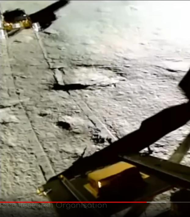 * Lunar Surface: I
went over a couple of videos from the
Moon taken by the Vikram lander. I was wrong about there
being no color images. (Duh!) As with the Apollo landings, this area of
the
area of lunar surface seen in color just didn't seem to have much color
to it. And (unlike on Ganymede, etc) complex organics weren't found in
the spectra, which also would pretty much rule out life. So the nature
of some of the surface features probably needs a novel
explanation. It still doesn't look to me like dust and rocks.
* Lunar Surface: I
went over a couple of videos from the
Moon taken by the Vikram lander. I was wrong about there
being no color images. (Duh!) As with the Apollo landings, this area of
the
area of lunar surface seen in color just didn't seem to have much color
to it. And (unlike on Ganymede, etc) complex organics weren't found in
the spectra, which also would pretty much rule out life. So the nature
of some of the surface features probably needs a novel
explanation. It still doesn't look to me like dust and rocks.
Features on crater rims look rather like ice melt
extrusions formed during the heat of impact (which are so common on
airless worlds in the
outer solar system, as water expands when freezing), but at +10°C
ice should have vaporized.
And no water was detected by the instruments. Some other sorts of
melt extrusions or crystalline growths, perhaps with sulfur (which was
detected)? Judging by the Pragayan's tracks, they seem pretty fragile.
Other shapes (below) are even more puzzling.
Could dirty water ice extrusions have formed in meteor
strikes, then in the ice vaporized and left brittle "shells" of other
minerals?
Come to think of it, wasn't
water expected only in deep
craters very near the poles where the sun never shines? Vikram didn't
land inside a deep crater (the sun was shining on it),
isn't that close to the south pole (69.4° south), and with a
temperature of +10°
any water should have boiled off (and perhaps accumulated in deeper
craters where the sun never shines). Why then did they expect to find
water? (Perhaps expecting a lower surface temperature? And of course it
is colder not very far down.)
 I increased the contrast of this
image. It seemed to have been reduced to best show the Vikram lander at
the
I increased the contrast of this
image. It seemed to have been reduced to best show the Vikram lander at
the
expense of dulling down Luna's actual surface. With no atmosphere to
scatter light, the moon is naturally a high contrast environment.
I am intrigued by this strange textured surface, so unlike the plain
dust and rocks at lower latitudes.
 Dust & rocks lunar surface
composition
nearer the equator - amazingly colorless.
Dust & rocks lunar surface
composition
nearer the equator - amazingly colorless.
ESD
(Eccentric Silliness Department)
* The Alps are eco friendly.
* Did you know? The fire breathing dragon is the only animal
that doesn't eat meat raw.
* Hoarseradishes can't even whinny.
* Atlas is rumored to have been reputed to have once said "Give me some
pickled eggs and a pot of chili, and I will make the universe expand."
* Did you know? Praseodymium is the only element with six syllables.
* The last thing you want to do with a piece of firewood is throw it in
the woodstove!
(I don't say you shouldn't want to throw it in the
woodstove... just that that will be the last thing you do with it!)
"in depth
reports" for
each project are below. I hope they may be useful to anyone who wants
to get into a similar project, to glean ideas for how something
might be done, as well as things that might have been tried, or just
thought
of and not tried... and even of how not to do something - why
it didn't
work or proved impractical. Sometimes they set out inventive thoughts
almost as they occur - and are the actual organization and elaboration
in writing of those thoughts. They are thus partly a diary and are not
extensively proof-read for literary perfection, consistency,
completeness and elimination of duplications before
publication. I hope they may add to the body of wisdom for other
researchers and developers to help them find more productive paths and
avoid potential pitfalls and dead ends.
Electric
Transport
Miles "Mini Cargo Van EV": for now, Fixed ratio Drive
[21st] There seemed to have been
vibration that coupled to the frame from the rotating parts. I got the
idea to put in a rubber "sandwich" cushion along the bolts that held
the planetary body [fixed ratio 5 to 1] and the outside of the housing
to the frame.
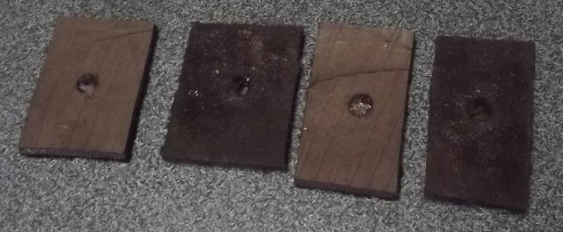 I
cut rubber squares from the sidewall of an old tire with a sharp knife.
I
cut rubber squares from the sidewall of an old tire with a sharp knife.
I
added these "vibration absorber" pieces. In theory
I should have put some rubber tubing between the bolts and the parts,
but that would have meant disassembling everything and making the holes
in the parts bigger to fit them. As it was I took off one bolt, added
the pieces, put it back on and then did the other.
Simple. The result was a
cushioning of the vibration but not its
elimination.
I put a video camera
underneath. I had the impression that
the bearing was rattling a bit inside its housing. But when I tried to
rattle it by hand under the truck, the only thing thing seemed loose
was the spline connection from the motor to the first shaft. That's
Miles's joint! From some previous incarnation of a mechanism I had put
four holes there for set screws. I now screwed some in, then drove the
truck around the driveway again. Better. Still vibration. Then in
the video I noticed that the driveshaft to the rear wheels wasn't quite
centered on the planetary gear shaft. Perhaps I can add some balancing
weights with some pipe clamps to hold them on?
I have for quite some time regretted not having saved the
original piece that slipped into the front of the driveshaft. I hang on
to so much. For once I had decided to "toss junk" (the original
transmission) and (predictably?) really missed this piece later.
Next: the programming. Acceleration is too abrupt, and taking one's
foot off the "gas" shouldn't be an emergency hard stop! And with
greater gear reduction the motor would have to turn faster.
Why wasn't the programmer communicating with the
motor controller? When connected before it had come up with the model
number "1238-6501", but nothing else. This time it just said "no motor
controller connected". Long story short the socket that the programmer
plugged into was s**t. A pin was bent and when the programmer was
plugged in, it just pushed out the back without even offering
resistance, and the plugs clicked together "fine". (And the feeble
"polarization" didn't absolutely prevent pushing them together the
wrong way around!) I was never a big fan of molex plugs. This doesn't
up their reputation in my mind. (and then Miles' workmanship - wrough!)
The reason I never noticed the obvious is the usual one: working in an
unlit space looking into a black hole. Who thought I needed a
flashlight to plug two plugs together that sounded a good "click" when
connected?
I couldn't get it to connect. I took the programmer out to
the Sprint and plugged it into the Sprint's Curtis "sep ex DC" motor
controller to make sure it still worked. It was fine.
Once upon a time (~1985) I had had Molex pins and the
insertion/extraction tools. I looked in my old alume toolbox made in
sheet metal class at Malaspina College in 1973 or '74. There they were!
But only female pins. I needed males. However, while the males in
the truck looked pretty round, I discovered that they wouldn't
mate unless they were both the same way around. 90° or
180°
off they wouldn't go in. So! The pins in the truck were probably
pushing out the back instead of inserting because they were in the body
the wrong way? Egads! A magnifying lens with a light said they were all
in the same way - at least now.
Wait! I hadn't plugged the 35 pin plug back into the motor
controller. Duh! Then I plugged the programmer back in, pushed on the
wire to push the errant pin in - it seemed to go in this time -
and turned on the key. It worked.
Finally! (Yes, I should have looked into it long ago. Also this
probably won't be the last time I have trouble with it, since nothing
is actually fixed. At least my paranoia that Miles might have cut a
wire to prevent anyone from reprogramming the truck is assuaged.)
I set "maximum regenerative power" from 100% to 25% to
reduce the hard braking effect when taking the foot off the "gas" - and
to make sure I could in fact change things. Yay!
It was night, so I left it at that. Mañana,
mañana, mañana is good enough for me, for me...
But later I found that nothing I changed changed anything.
The truck continued to handle just the same. And when I tried to raise
the maximum RPM limit, it would go up by one RPM and then back to the
original value. Yikes! Now What?
Other
"Green"
&
Electric
Equipment
Projects
Air
Compressor Designs
for Open Loop Air Heat Pumping ("OLAHP")
I had paused the OLAHP
project of spring 2020 wanting a better air compressor. I
conceived that a continually rotating unit would have to be better - in
theory - than ones where a piston was driven repeatedly back and forth.
"Screw compressors" aren't that efficient. The ROVACS
compressor-decompressor design looked much
better in theory than in buildability and likely actual performance.
And I had decided to proceed without the decompression recovery section
(at least for the next prototype) because it made the air piping and
compressor-decompressor too
complex. A rotary compressor I saw some months back was in production
and was supposed to be 30% more efficient than others. But the
available units were too big for my purpose (and costly) and had some
complex gears too hard to make DIY.
On the night
of the 17th I couldn't sleep. Instead I was
thinking up rotary air compressor designs. At 4 AM I got up and drew up
one. In the morning I looked on line to see what else there was.
I
found a somewhat complex one that probably had a fair amount of
friction, and a paper describing another with vanes something like an
improved ROVACS but without the decompression part. The paper went into
the likely amount of friction divided into various frictional
components. [I forgot all about it until I went to write this report.
If I hadn't grabbed the images from the web site I'd have forgotten it
entirely and missed that the offset circular outer housing is a better
idea!]
I looked at mine again. It
had intrinsicly less friction
than any other design I had found. The vane(s) pivoted on a hinge
instead of sliding in and out of the rotor. It could be made with an
arbitrarily short compression stroke, eg, less than 1/4 of the circle,
and there was no vane friction except during it. It could be made with
any number of rotating vanes on the rotor or just one non-rotating one
in the "compression ramp" (or "n" compression ramps around the
circumference, where "n" could be 1 to about 3). Having just one
compression ramp with highest RPM operation would minimize air leakage
losses around the vane(s). Two might make for better rotary balance of
forces.
[18th] In the evening I thought the next logical step could be a curved
bellows type mechanism as a separate assembly. All the air goes through
the bellows. The only function of the rotor would be to press on the
curved inner "ramp" of the bellows and squeeze it shut each time as it
goes around. It could even have a little wheel so there's no rubbing
friction from it. All the air compression design is concentrated into
the bellows. (of course there may be two+ sets of bellows to balance
the rotary load.) This seemed incredibly simple. Why has no one thought
of this before?
Then I remembered that a key objective is to minimize
oscillating masses. The trouble with a typical piston is that it's a
solid mass repeatedly being pushed and then pulled, and changing its
motion uses energy. A bellows might be all right if the inner ramp part
were very light. What would be lightest? Rotating vanes with light
alume vanes. Was I back to last night's idea?
But the inside of the "bellows" could be a lightweight
curved alume "vane" too. It would have to be longer than the rotating
vane, of course. But if the stroke was kept short, not so much longer,
so not much more air leakage. And with the rotating shaft pushing it
via the wheel, the friction might be a little lower. I conceive that it
would probably be just as good. And perhaps the lowest air leakage (and
maybe lowest friction) might be had with a lightweight "bicycle pump"
type cylindrical piston, pushed in as the ramp is pressed by the rotor
wheel? Or perhaps the piston shaft could have the wheel and an
elliptical rotor could be the ramp?
Yikes! All these ideas!
[19th] I'm now thinking of "bicycle pump" lightweight pistons, pressed
by a ramp from two bearing wheels on opposite ends forming an "oval"
rotor. Only the piston materials inside the cylinders need be able to
withstand heat.
I've been using a working pressure of about 60 PSI, four
times atmospheric. If the compressor was made so the compressed air
space was ~1/2 of the intake air space, that should work. (That's
double the air per volume, at double the temperature too, is 4x
pressure.) The pressure would thus be self limiting. Furthermore, if
the compression ramp was bidirectional, then when the pressure already
in the system was such that less air, or almost no air, was pushed out
of the cylinder, then as the ramp passed maximum, the remaining
pressure in the cylinder would push the piston out and the rotor
forward instead of resisting rotation. If it was made with two
alternating compression units, the cylinder pushing would be assisting
compression of the other cylinder.
This suggested that the compression stroke could be 1/4 of
the rotation and the decompression the next 1/4, with the pistons 90
degrees apart. With a two ended oval, after 1/2 a rotation the cycle
would repeat. The motor only need do a little work - friction plus air
actually pushed in - even if the system was compressed. The level of
heating would be regulated by the amount of air being released to the
outdoors at the end of the piping.
Such a compressor should use "theoreticly" no more power
when the system is up to pressure than when it is just starting up.
So, this compressor and system still wouldn't use the air
coming out the cold end. It would still be above outdoor temperature
with some pressure remaining, and hiss out the end outdoors, unused.
How much would this actually reduce the COP, and what then might be the
attainable COP?
If the temperature "lift" was from 0° outdoors to
30° in the indoor radiator (in degrees kelvin, 273° to
303°), that's 303°/(303°-273°) = COP 10.1 theoretical
maximum. But this is
where the open loop air has closed loop refrigerant beat all to pieces:
we may count on the indoor/outdoor heat exchanger (AKA "heat recovery
unit") to raise the incoming air temperature from 073° to, say,
288° (15°C) as it enters the building. So the compressor does
less work: 303°/(303°-288°) = COP 20.2. If we say that the
overall efficiency of the system with the efficient compressor, in
spite of the loss from the wasted exhaust air, is 40%, then COP =
20.2*.4=8.08. Not ideal, but 800W of heat from 100W of electricity is
nothing to sneeze at considering present refrigerant based systems
hardly achieve COP 4 even with a mild outdoor temperature, and perhaps
COP
2 when it's freezing outdoors. If we captured the outgoing air and
forced it to help compress the incoming, perhaps we could achieve 60%
and have COP 12.12. And everything depends on the efficacy of the heat
exchanger. It needs to be really effective. I've heard of "heat
recovery ventilation" units
capturing up to 90% of the heat energy as indoor and outdoor air is
exchanged, and if that can be attained it would be fabulous. But that
probably depends on a fairly slow rate of exchange, and an air
compressor is
going to suck in quite a bit of air.
One can throw all sorts of figures and adjustments into
the modeling, but once again I think the real figures are only going to
be found by "build, measure, and see". Hopefully this compressor is
substantially higher efficiency than other small compressors and can
unlock the above sorts of results.
[24th] The more I thought about it, the more I thought about
practicality. I started thinking of basic principles.
1. To minimize leaks, the moving part should have the minimum line
where two moving parts need to seal. That would be a round circle, as
with a piston in a cylinder.
2. E = .5*M*V^2, so reducing the velocity of parts that are
pushed in different directions over the cycle saves much energy.
Halfing the velocity rduces waste energy by 4 times -- assuming it
doesn't result in much more air leaking around the seals.
3. Again to minimize energy losses, the minimum amount of mass 'M'
should be being forced to change directions during the cycle. We want
the most force being used to squeeze air, not to shove metal around.
I figured my rotary compressor design was probably better
than those I've seen on line, with lightweight alume vanes pivoting on
a pin instead of sliding in and out. But what about something fairly
equivalent that was also easy to make? or even, was already made? My
thoughts kept coming back to the bicycle hand pump. It's a piston in a
cylinder, but compared to those in powered piston air compressors it's
a really lightweight pisto, and it's HUGE with a length of stroke that
seems absurd in a powered tool. So it has the three desirable
characteristics: minimal leak line, low velocity, and low piston mass.
I was going to go to Masset bicycle shop and look at what they had, but
my day got changed and I had to skip the trip. Instead I looked at my
own two bike pumps in the garage.
With the hose disconnected the handle of the smaller one
fell from top to bottom very quickly. I melted some wax and waxed the
pistons, and it fell even faster - almost freefall once it was warm.
The situation changed entirely if I blocked the air outlet. Then it was
hard to press half way except by waiting for air to leak out. So it
seemed to be doing almost no work except for actually compressing air -
high efficiency. If run by a good motor at a low RPM, I'm pretty sure
this would still be substantially the case. Further, if limiting air
compression from ambient to ambient+60 PSI (+4000 mBar, +4 atmospheres)
by squeezing it into a space from full to 1/4 the length of the
cylinder on each stroke, it would never exceed the desired pressure. If
the system were already full of 60 PSI air, no more would be pumped in,
and the pressure in the pump would push the motor through the
intake stroke, making up for what it used on the compression stroke.
Except for inevitable losses, power would only be used when the pump
was pushing in air. The heating - and the electric power needed - would
be regulated by how fast the air was permitted to flow through the
system, but even if the output got blocked by condensation the pressure
(and the compressor temperature) wouldn't build up to a dangerous level.
All these things convinced me I should try making a
compressor with the waxed bicycle pump as the key component. If it
didn't last long in use, one could keep the principle but beef things
up as necessary, hopefully not by adding a lot of mass.
A low RPM motor, or one geared down, would have a cam near
the outside of a flywheel, with a bearing, driving the plunger of the
pump. It'll look primitive & low tech. But should be fairly simple
to fabricate.
[25th] But my mind also
kept coming back to the fact of losing 29% of
the input energy if the air was allowed to hiss out the outside
end still compressed. (Probably it's less since the air is cooled
to below its starting temperature?) The great benefit of the ROVACS
design was the ability to use the outgoing air so effectively to help
compress the incoming air. My hinged design depended on the compressing
air to hold the vane closed. For decompressing air the vane would have
to point the other way. But perhaps vanes pointing both ways might be
placed on the same rotor, and appropriate air holes placed to make that
work? Or, there might need to be two rotors, compression and
decompression? It seemed worth working on the design, simple tho the
bicycle pump would be.
I thought of the heat
radiators and the radiator for the
outdoor air heat exchange. The most effective one I had done was the
first one with the heat exchanger inside the room/house. Assuming
imperfect insulation cold air coming in would be warmed a bit by room
air as well as by the radiator from the "spent" heating air. When it's
outside, the incoming air is cooled a bit by outside air, and that heat
goes into the great outdoors. Having the outdoor heat exchanger indoors
fits in well with having the cooled compressed air return to compressor
so its energy can help compress the next cylinder. And rather than
drawing from a duct, the compressor can draw room air. If that's
already 20°c and is heated to 35° potential COP from the
compressor is 308°K / (308°-293°) = COP ~20. If counting
everything the efficiency is 40% then COP would be 8.
It would seem that the decompression should be active at
the same time as the compression for the most balanced effect. But
if they are on opposite sides of the rotor, they will both press the
rotor the same direction axially; hard on the bearings and more
frictional losses. To have balance there must be two of each - two
compressors opposite each other and two decompressors opposite to each
other. (Or there could be 3 of each, or 4...)
Thus, two vanes in each direction, two compression ramps
and two decompression. Only the cooled, decompressed air goes outside.
At this point it may be even colder than the outside air, and may need
a little heating wire in the duct to keep it from icing over.
Once again I couldn't sleep for no evident reason. This
time I got up after 2 AM and drew up the design. I put the light out at
3 this time got to sleep.
The 1970's ROVACS -
ROtary Vehicle Air
Conditioner System: Compressor + Decompressor
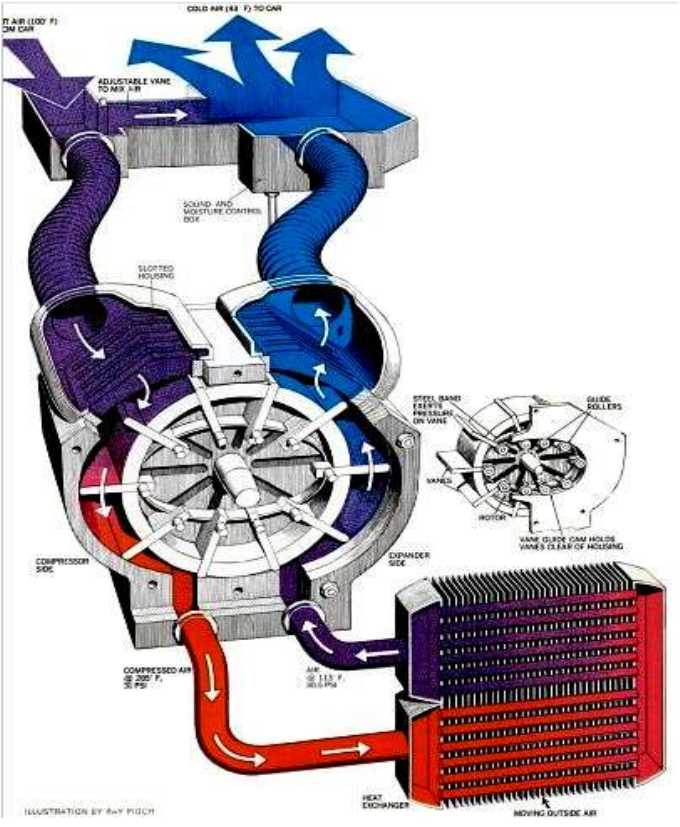 [27th] It occurred to me that what I had drawn was pretty
much a "ROVACS" but with pivoting vanes instead of vanes that slid in
and out from the center. I think that while ROVACS was a great idea in
theory, the mechanics of the sliding vanes killed it. (I
now note "guide rollers" in the tiny print by the tiny diagram.
Probably helpful, but yet more complexity! My opinion still stands.)
[27th] It occurred to me that what I had drawn was pretty
much a "ROVACS" but with pivoting vanes instead of vanes that slid in
and out from the center. I think that while ROVACS was a great idea in
theory, the mechanics of the sliding vanes killed it. (I
now note "guide rollers" in the tiny print by the tiny diagram.
Probably helpful, but yet more complexity! My opinion still stands.)
I think hinged vanes held closed by air pressure should
work well.
Overall Description of the Heating System
(Recap)
For heating a room in a building, air can be drawn into
the compressor
from the room itself at say 20°C, needing a lift of only 15° to
hit the first radiator in the room at 35°. A fan blowing across
that radiator brings the heated, compressed air down to (say) 25°
as it
heats the room air to above 20°. Heating by only 15° gives a
maximum (theoretical) COP of 20. [293°K /
(308°K-293*K) = COP 19.53]
The second and unique radiator in the OLAHP heating system
is the
indoor-outdoor air heat exchanger. Air is drawn through the outer part
of
this into the room by the suction of the compressor intake. Presumably
the compressor air intake is not far from where the passively warmed
outdoor air enters the room, but there is no need for a direct
connection. Instead, the room gets a good supply of fresh but warmed
outdoor air. (A direct connection may be more practical in some cases.)
As the still compressed air goes into this second "linear"
radiator, the indoor-outdoor air heat exchanger, it is cooled by the
incoming outdoor air, warming it and itself cooling. If it is (say)
0° outside, perhaps the (~25°) compressed air will be reduced
to ~5°, while the outdoor air entering the building enters at
~15°. So we had 20° being compressed to 35°, going through
two radiators, and returning at 5°. Then the 5° air, still
compressed, is
sent through the decompression side of the air compressor unit, and may
then exhaust to the outdoors below outdoor temperature. The
exchanger did half the work passively, the compressor the other half -
much less electricity.
High effectiveness or efficiency of all components is
vital to getting a high COP. Obviously the better the indoor-outdoor
heat exchanger works, the less work the powered part has to do and the
better the system will perform. If the compressed air exits this
exchanger at 2° and air into the room is already warmed to 18°,
it's considerably better than if it's 7° and 13°. And if the
room radiator only needs to be heated to 30° instead of 35°,
theoretical COP rises to 30. And the more efficient the compressor is
the less electricity it needs to do its part until the only energy is
going directly into compressing the air and the maximum assist is
obtained from the decompressing side.
Since the radiator is putting out 35° and the incoming
air is 15°, presumably the room air would stabilize somewhere
around 25°.
Since the insulation isn't perfect the room will be somewhat cooler,
that depending how fast it would cool if unheated, and how much much
air is going through the system - how hard it's working to keep the
room warm.
I drew the vanes with thickness for UHMW plastic, but the
vanes are the parts that oscillate in and out and should be kept light,
so they should be alume and the elliptical outer wall as well as the
top and bottom will be the slppery UHMW faces.
I think I'm getting close to wanting to actually start
building and seeing how things fit. But do I have the time? It's going
to take more time than cutting firewood. But I'll need a lot less
firewood if I have OLAHP. There's "maintenance time" and any left over
is "capital time".
As I brought
in the images I had taken or copied in writing up this report, I found
one I had copied from
a newer ("HEVC") rotary air compressor design on line and then
forgotten about. (Yes, I was looking for something "off the shelf".
Didn't
find it. I neglected to copy the URL.) The offset circular outer part
would be simpler than the ROVACS elliptical one yet it could achieve
the same thing. A refinement was that the outer housing rotated to
reduce friction with the vanes. However it was only a compressor.
Again I think pivoting vanes should be more practical than
sliding ones and backward facing ones could do the decompression. I'd
probably still have 3 blades each way.
(For December I have found another improvement, a rotary "air
expeller", which is a simplification and efficiency increase of the
decompression component.)
Indoor Radiator: Off the Shelf Unit!
[29th] I had also started thinking the a typical indoor radiator unit
from a refrigerant based heat pump might be very good for the OLAHP as
well. It would simply have air going through it instead of refrigerant.
So I asked my friend Perry about the indoor units for heat pumps. Perry
has taken up installing, cleaning and repairing [refrigerant based]
heat pumps and has gained much expertise in the subject. This day I
picked up a discarded unit from him. It was discarded because the logic
board in it had quit. By the time I had it apart - all that decorative
and air-aiming plastic and multiple internal components - I understood
why it might not be worth disassembling one just to replace a part. It
was a real 3D jigsaw puzzle, complete with plastic clip fastenings and
two dozen bolts, all intricately woven together. (I started to regret
taking it apart and having pieces everywhere.)
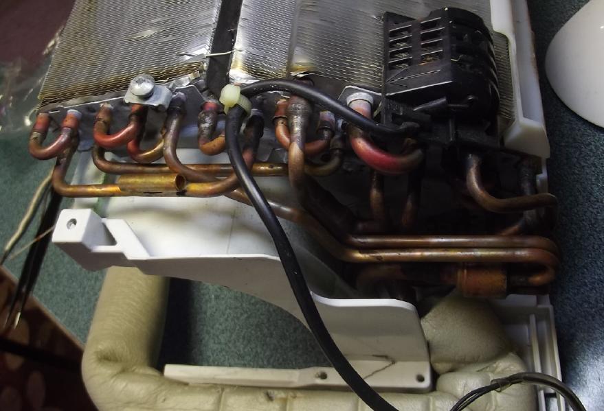
Once I saw the inner essence I thought it looked admirable. Layers of
small tubes in very finely spaced fins wrapping around a long "squirrel
cage" fan to whisper the air through all those vanes without being too
loud.
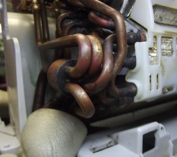 The piping seems quite small for compressed air, but the
thin input pipe [I could cut it shorter] immediately goes into a
manifold
to four very thin pipes in parallel into the radiators. Four "T" joints
combine them again into the slightly larger output pipe. According to
Perry,
the small input pipe would hold liquid refrigerant, which would turn
into gas in the radiator, so the output pipe was larger. (Hmm, isn't
that for air conditioning? It does say "Air Conditioner" on the box.
Wouldn't heating reverse the flow?)
The piping seems quite small for compressed air, but the
thin input pipe [I could cut it shorter] immediately goes into a
manifold
to four very thin pipes in parallel into the radiators. Four "T" joints
combine them again into the slightly larger output pipe. According to
Perry,
the small input pipe would hold liquid refrigerant, which would turn
into gas in the radiator, so the output pipe was larger. (Hmm, isn't
that for air conditioning? It does say "Air Conditioner" on the box.
Wouldn't heating reverse the flow?)
 If there was
any marked decompression through the thin
pipe circuits, the unit would simply have to be derated; less air flow
and less heating capacity than it had with refrigerant. I think it'll
be enough and more for actual heating with the prototype.
If there was
any marked decompression through the thin
pipe circuits, the unit would simply have to be derated; less air flow
and less heating capacity than it had with refrigerant. I think it'll
be enough and more for actual heating with the prototype.
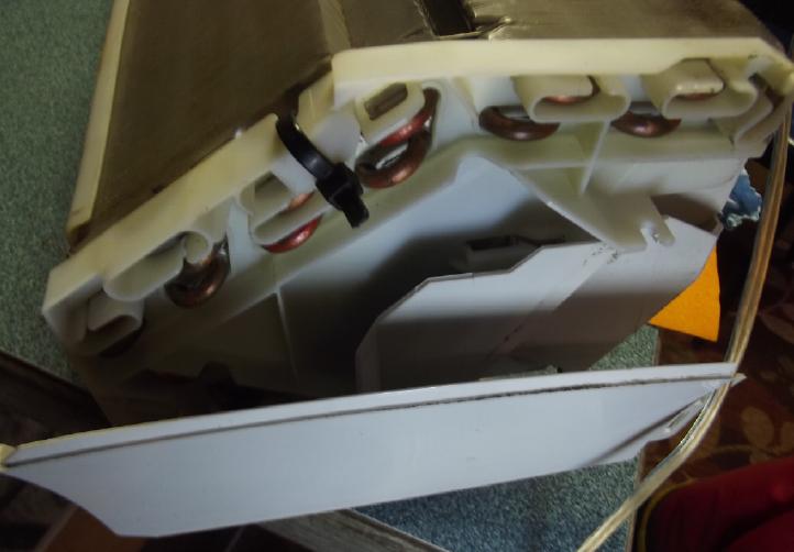
The only problem is that
the motor driving the fan (brushless DC -
white circle at top end) plugged into the dead logic board with a five
pin plug. It could be hard to fit any other motor. Could the motor be
run without the board? With that tiny plug and skinny wires it claimed
to be 280 to 340 VDC, 36W, 1510 RPM. Beside the mostly Chinese writing
the pinout was given in a milliscopic picture. (I do mean small... I
used a microscope lens to ascertain that those actually were letters
there.)
1- Vm (red)
(no pin)
2- Ground (black)
3- Vcc (white)
4- Vsp (yellow)
5- FG (Frame Ground - blue)
Perry said it ran on pulses. Maybe Vsp is Speed Pulses -
PWM? And 300 volts DC sounded plain weird as well as the wire
insulation being probably good for about 50 volts. Well, there were no
visible decimal points and the unit did say "208 to 240 VAC", which
would rectify to around 300 volts DC. Youch! Maybe I can make it work
on
120 VAC rectified to 150 VDC, with the speed control simply on
"enable"? I guess I'll try it because replacing the motor would be
hard. (is "Vcc" 5.0V or 3.3V? or???) I'll have to solder up some
proto-board with a diode bridge et al.
There are refinements that must have run off the logic
board
like self aiming louvers (which were probably controlled by the coil
temperature) that I'll have to forgo. Anyway I'll make it
work. Here's a major component for this project that I can
(did) get "off the shelf" instead of having to make.
Cabin Construction & DC Wiring
[1st, 2nd] I put up the
remaining plywood and then "tyvec" on the last outside
wall section, leaving just the garage door and a couple of windows with
no glass in them yet. Seems I was just in time. It had been quite dry,
but rainy winter weather began that evening. There is still much
"touch-up" to do on the outside, and the metal sheeting over that wall,
but now I could continue the inside work during bad weather.
When I went to staple up the tyvec, I figured my 'tenis
elbow' was pretty much healed and grabbed the staple gun. After 4
staples
I thought I felt a twinge in my arm. I got the regular paper stapler
from the house and put in two or three of the small staples in each
place. Later my elbow had pain
again. Good thing I didn't continue! Won't this arm ever
heal?
[5th] I thought of how antennas can be grounded or connected to low
voltage equipment at one end and pick up signals at the other end. With
the cabin roof 34 feet long it may be big enough to act as one, which
might let some amount of power line field through to inside. I decided
to ground all four corners and the middle of the long sides with a
copper pipe grounding rod, a wire to
the wall and a wire to the roof. To ground
the steel-faced doors I also ran a ground wire to the hinge of the
door, and put a stainless steel screw from a "bump" on the hinge
through the inside metal face of the door. As the hinges are screwed
into the wooden edge I suspect they don't contact the faces. (I am
however counting on connection through the hinge pin.)
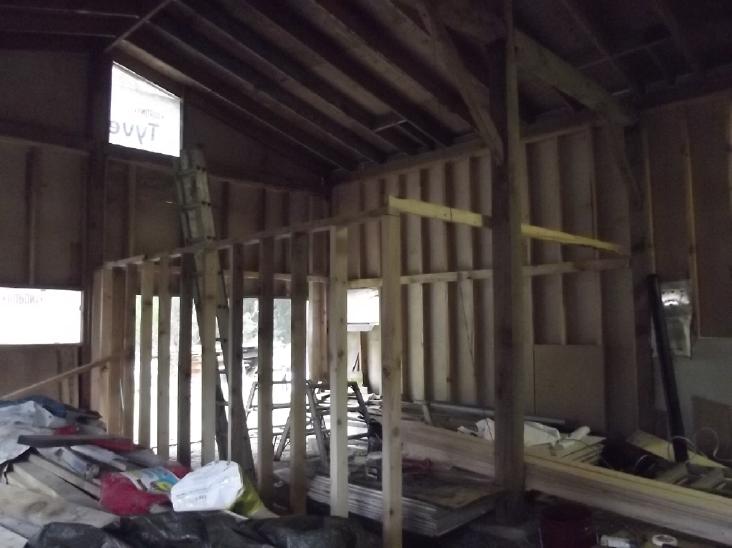 My carpenter friend Dan helped me design the garage framing and we did
the side wall. I had originally thought to do an angled wall over to
the
post near the center, but he talked me out of it. It would have been
hard to walk around a car if it was so narrow at that end.
My carpenter friend Dan helped me design the garage framing and we did
the side wall. I had originally thought to do an angled wall over to
the
post near the center, but he talked me out of it. It would have been
hard to walk around a car if it was so narrow at that end.
Next I framed
the ceiling/upstairs floor joists over it. I used doubled-up 2 by 4's
in the area the roll-up garage door needed space above. That lowered
the floor 2 inches over using 2 by 6's. I used 2 by 6's notched at the
ends for the rest..
[6th] 3/4 inch thick tongue
and groove boards seemed to be cheaper than
3/4 inch plywood and I decided on them for the floor. I glued the first
6 to the joists - "wrong way up" so the floor wouldn't have grooves in
it. The boards were very conveniently the full 16 feet length of the
room. Instead of nailing them I pushed them together and screwed short
pieces of wood to the joists at the open edge so they couldn't ooze
apart before the glue dried. I also found that if I screwed near one
end of the piece, I could pull the long end away, then screw it down,
making it a lever to press the floor boards together more strongly.
[7th] I glued 7 more tongue & groove boards onto the joists to
continue the upstairs floor. I found that walking headroom upstairs
(for me) was about a meter from the wall - more comfortably 4 feet.
That's 1/3 of the room I won't want to walk in. I also noted that if
the rafters weren't there, it would be standing headroom everywhere to
the actual roof. It is now tempting to think about notching out some
rafters to make more headroom closer to the wall. OTOH there are a
couple of problems with the idea.
Indoor View from 2nd floor
(Clutter, clutter -
ug!)
Hmm, I could get rid of some of that ceiling insulation by putting it
in the ceiling.
I can reach it now in the 2nd floor corner.
Home Depot in Prince George
resold the garage door I had bought before it could be delivered to me.
(Thanks a lot!)
Then I ran across some never used furnace ducts discarded
at the refuse station. I took some to use for the outside skin of a
garage door I would make myself, with a 2 inch extruded styrene foam
core and epoxied polypropylene inside.
[8th] I thought of the styrofoam "boards" that were to compose this
garage door. What if they were oriented
verticly instead of horizontally? I didn't want a big "barn door" in
two halves to swing in the wind, but it could be a "fanfold" door,
opening off to one side. It would have (I imagine) rollers in a track
on top, and
some sort of guide at the bottom.
Inexorably drawn to this theme, it then wouldn't need the
vertical space above for the "roll-up" hardware. I could lower the
upstairs floor by the five or so inches or so needed to have standing
headroom throughout (at least for me: 5'8") and at the same time the
door itself could be a little taller, say 6'6", so people up to about
6'4" tall
wouldn't hit their head.
Furthermore, if the 24" wide opening-end panel didn't have
a top roller, it could be swung open like a regular door without
opening the rest, making it a "two in one" door. As it's the only door
at that end of the structure, that's a very attractive idea.
There are a couple of downsides. The obvious one is that
five 2" thick panels plus their faces "stacking" at one end reduces the
door width by about a foot. But that's workable. I had framed 9 feet,
but they do make 8 foot wide garage
doors. Being so short verticly I wasn't going to get the truck in there.
The really nasty drawback is that I had just finished
making and installing the inside wall frame, the upstairs floor joists
and part of the floor. Everything was carefully leveled and boards
glued and screwed in place to the outside walls at the design height.
Mostly everything was screwed together, but a few things are glued
including the tongue and groove floorboards I just put in. To change it
now, all this has to be undone and redone, with the wall studs cut a
few inches shorter. The glued
boards won't come off easily and might have to be replaced. To
raise the garage door top 4 or 5 inches I'll have to saw out the wall
to the new size and redo (again!?!) the top of the frame.
I must pause, think about how to do this door, and if I
see no obstacles, decide if the obviously better result is worth all
that. I don't mind "low", but I do hate rooms without standing
headroom. (Not much later)... Nah! It's just too much work to redo.
Heartbreaking! If I'd thought of it 10 days ago or more, it would have
been simple. Even 4 days ago I'd probably have changed it. After all
this time working on this, I did the framing and then thought of the
better door plan in just the wrong order!
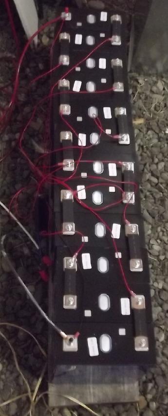 [13rd] I
decided it was time to tackle the DC solar installation in the
cabin. I got out 12 of the new batteries from Deligreen, 290 AH, 3.3V
and
carted them out. I screwed the solar charge controller and a couple of
circuit breakers onto the same board on the wall that I had recently
remounted the two grid ties on, near the one and only 120 V AC outlet
in the corner.
[13rd] I
decided it was time to tackle the DC solar installation in the
cabin. I got out 12 of the new batteries from Deligreen, 290 AH, 3.3V
and
carted them out. I screwed the solar charge controller and a couple of
circuit breakers onto the same board on the wall that I had recently
remounted the two grid ties on, near the one and only 120 V AC outlet
in the corner.
Then I started connecting wires. Mostly heavy #8 AWG. They
seem pretty fat, but I've seen a #8 cable get hot running an outboard
motor for a while at (IIRC) around 50-60 amps. I fed the charge
controller its solar voltage from the terminals on the grid ties
already connected to the solar panels, and put the other terminals of
the ties together "-" to "+" so the four solar panels were 2 series 2
parallel to give ~50-80 VDC, 0-18 A to the charge controller. I simply
presume it needs more than 40V if it's to charge the battery to that
voltage, because it doesn't say. (I may add two more solar panels to
make six on the cabin & 27 A to the charger.) The grid ties and the
DC charge controller can fight over the power from the solar panels. If
the battery needs charging mostly the DC unit will win. If not, it will
cease drawing current and leave the power for the grid ties.
I had a "Daly" charge balancer (or "balance charger") for
12S lithium-iron phosphate cells. It's pretty light - 15 A charge and
30 A discharge, but it should do the trick for now. I wired up its 13
sense wires and connected them to the cells before I tightened the
nuts. I tested to make sure I had them in order. They were, but there
were two insecure connections to the ring lugs - one was "no
connection" until I pushed on it. I crimped them again with the
crimpers reversed to get a different bend, and that seemed to fix them.
Late that
evening I connected the "Daly"s heavy wires and
hooked everything up, except I didn't plug the sense wires plug into
the balance charger nor turn on any breakers, preferring to wait for
daylight and a fresh mind before rechecking the wiring and powering
everything up.
[14th] Everything seemed to work well, but it could use some more solar
panels to charge faster even with the sun shining, esp. in winter.
I've never used a solar charge controller's "load" output
before because other controllers I've used have a current limit of like
"5 amps" on that output. But reading nothing in the little piece of
folded paper that passed for a manual, I assume that the "load" output
of this 100 amp controller can actually supply 100 amps, so I wired it
to a "main breaker". By using that instead of connecting straight to
the battery, the controller's low voltage cutout should protect the
cells from serious overdischarge. (The charge balancer could also have
a low voltage cutout. Why don't they mention these things in the
instructions?)
The charge controller, a type newly appearing on
AliExpress.com, seems good except that it doesn't seem to be very good
at the "MPPT". It just drags the solar panels output down to the
battery voltage, which heats them and doesn't extract the most power
from them.
With nothing said, the skimpy manual - a tiny piece of
folded paper printed with about 6 point font, if - left me also simply
having to assume it was a buck circuit rather than boost, that the
12/24/36/48 volt "auto-voltage select" wouldn't mistake 40+ volts of
lithiums in a well charged 36 volt lithium system for a 48 volt system
instead and try to charge them to 54 volts. These are not minor
details. With the
"PowMr" controllers I have to be very careful to keep the charged
voltage under 40.0 volts, which is less than 100% charge for the
lithium ion cells. (I guess the 6 point font in the manual was to match
the 6 point font on the LCD display. I finally dug out a flashlight and
some reading glasses.)
I set the charge voltage to 40.0 V. 3.34V per cell
is probably a good charge voltage: 3.34 * 12 = 40.08 V. Lithium-iron
phosphate cells are supposed to be safer than lithium ions and it could
certainly be charged to 42V (3.5 per cell) to top it up faster, but
especially in an unheated space I won't go higher. The "float charge"
voltage, intended for lead-acid cells, is 41.4V. The manual says you
can change it, but in the program voltage selecting sequence H[igh] -
F[loat] - L[ow], "F" is missing and it goes straight from "H" to "L". I
trust it won't finish charging to 40.0 and then decide to raise it to
41.4! Again the manual is ambiguous. (Yes it does!)
When the sun was bright and long winter tree shadows
weren't shading the collectors it was charging at almost 10 amps. I
plugged in the 2500W inverter and ran a 150 watt incandescent light
bulb for a few minutes. (Ooh, it got hot! Oh yeah, incandescent light
bulbs!)
One thing this system doesn't have is a watt-hours meter.
I figure it put around 1 KWH into the battery over the day. (You would
think they would put one into a solar charge controller since it knows
all the exact figures anyway. But I haven't seen it in a stand-alone
controller.) And with the power running both directions between battery
and controller, putting a meter in-line isn't going to work. Hmm.
[15th] I took the DC LED "light bulb"
out of my livingroom lamp and put
in the 150W incandescent. I plugged it in in the cabin. It glowed
dimly, used .67 amps, and was about 25 watts. It still got kind of hot.
Then I tried a 250W heat lamp. It drew 1.09 amps and used 43 watts.
Pretty small to use for electric heaters - hand warmers maybe! (I
remember using light bulbs for both heat and light in my office about
2010, just before there were LED lights. Pretty bright room, but
otherwise it would have been an electric heater and a dull room, using
just as much electricity.) At such low voltages and powers, the bulbs
should never burn out.
The charge controller had a loud buzz, varying
in intensity and only sometimes present, not when charging hard but
when charging lightly or running a load like the bulbs. It sounds like
about 50-60 Hz. What has a DC unit to do with line frequencies? (I
bought two of these. I wonder if the other one is the same way? Hmm, I
never heard that buzz again after the first day.)
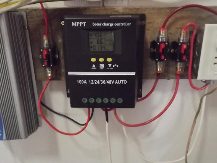 In clouds, it's dragging the solar panel outputs (2 in
series: 50-80V) right down to the battery voltage of 40.3 V, and
drawing 2.7 amps from them - obviously all the amps they can give. It
says "MPPT" on the front, but "maximum power point" should be well
above that voltage, at least 50 to 60 volts, with almost the same
current. I'm dubious about its claim to be "MPPT". The PowMr solar
charge controller seems much better in that regard, never pulling the
panels below about 50 volts.
In clouds, it's dragging the solar panel outputs (2 in
series: 50-80V) right down to the battery voltage of 40.3 V, and
drawing 2.7 amps from them - obviously all the amps they can give. It
says "MPPT" on the front, but "maximum power point" should be well
above that voltage, at least 50 to 60 volts, with almost the same
current. I'm dubious about its claim to be "MPPT". The PowMr solar
charge controller seems much better in that regard, never pulling the
panels below about 50 volts.
Which leads to the next question: If I've set the charge
voltage to 40.0, why does the meter read 40.3 and it's still on full
charge? Chinese electronics and programming certainly deserves close
scrutiny. Later: up to 40.5V. Later: 41.2V, sun came out, charging at 8
amps. I guess it's going to take it up to the lead-acid "float voltage"
of 41.4V regardless. The manual says the float voltage is adjustable,
but following the instructions the sequence just skips past "float
voltage adjust". Nothing seems to be what it seems. At least, by
the numbers, it has decided it's a 36V battery. With the PowMr, it was
"12V" then x1 x2 x3 or x4, and a couple of times it was trying to
charge my 36V up to 48V. That can be a "house burns down" error.
Anyway, I have a 40V panel light in the celing in the darkest corner,
with a
light switch by the door, and now it's recharged by the sun. I
also plugged
in a lamp. Just to try it, I unscrewed the 12-60V DC LED light "bulb"
and put in a 250W (@120V) incandescent heat bulb. At 40V it put out
about 53W - not much more than a hand warmer. I made a long 40V
extension cord and put the lamp (LED again) upstairs.
Later I plugged in a
1500W electric resistance heater (one with radiat coils, no fan or
electronics) and
had a 40V, ~150W heater (4 amps). The elements don't quite glow even in
the dark, but it doesn't buzz because it's running on DC, and I can
feel the heat. Might be enough for a small room if
it's not too cold out, but running on batteries one might want it on a
timer - one can see the millivolts dropping with the minutes with the
heavy load on the batteries. (Need DC timer!) It's an incentive to try
and get the open loop
air heat pumping working, to get at least 1000 watts of heating power
from that same 150W of electricity.
After thinking about it, I
decided to
run two cables of #14-3 AWG to wall outlets intended to be capable of
heavy loads, of which I had placed one where I thought I just might
have a countertop. (I have plenty of wire, having originally thought I
would wire the building up with plenty of 120VAC like most structures,
and after buying plenty of wire already, I got three more big spools
for peanuts at a garage sale.) "AWG" doubles in cross section with each
three of its reverse-numbered gauges, and "3 wires" also has a fourth
bare wire for "ground". So if one puts all the wires in the cable
together: two #14 together makes #11. Two #11 together makes #8. One
four-wire cable for "+", the other for "-". #8 AWG is rated for 40 amps
continuous.
On the 26th I took the gyproc off the wall and replaced
the "#12-2"
cable I had wired the outlet with with two "#14-3", then put the gyproc
back on. This is why I like screws rather than nails. I simply ran the
two spools of wire across the floor to where I plan to put the
electrical closet.
A day or two later I finished insulating that wall section, and started
the next one with the leftover pieces in the bag. That's three bags of
insulation in the walls, about 10 bags to go. For the walls. (I think
I've mentioned that fiberglass, which I hate working with, is the only
insulation I can find to buy in Northern BC. Lower cost, friendly,
arguably higher "R" value and (surprisingly) more fire resistant
cellulose fiber is simply not available. Nor are cellulose and other
fiber batts available in Europe to be had in North America. (...or one
can get even more costly and equally environmentally unfriendly rock
wool or extruded polystyrene "boards".)
If I had loose filled cellulose fiber behind gyproc and
then removed
the gyproc it would be something of a mess. However I would have
insulated later when all was more ready, instead of having to insulate
before putting up wallboard.
Shielding
from
Power Line Electric Fields
Not only do power lines seem to be the probable cause
of "everlasting" tinnitus, but looking on line I find that children are
four times as likely to develop leukemia in homes with higher fields,
and it even seems to depend where their bed is situated WRT outlets or
electrical equipment wiring.
There are two measures: milligauss magnetic field and
volts per
meter of electrical gradient. The magnetic component depends how much
current is flowing in the lines. Even without a meter, one may estimate
the "volts per meter". If the power poles are 10 meters high and the
line on top is 14,400 volts, the gradient through the air to the zero
volts ground underneath is 1440 volts per meter (RMS). The farther one
is from the poles, the lower the gradient. I suspect that it is this
gradient that is related to tinnitus rather than the magnetic aspect.
In that case a powered AC line with no load is just as bad as one
driving a heavy appliance. But I could be wrong or possibly both fields
could be play a part.
As I started to realize that a big metal roof grounded
only in one
corner is probably just a big antenna for such fields and that I should
ground all four corners of my cabin (and maybe in the middle of the
walls too!), I soon realized that the house should be treated the same
way, and that with the power poles so close I might cut the intense
blast of my tinnitus even while spending most of my time in the house,
by placing several grounding rods around the perimeter, each connected
to the metal roof. The more ground points, the more it's like being
underground instead of exposed. With only one ground in one corner, the
extensive metal roof may be doing little or no shielding. And in fact
there are three separate roof sections, with those over the kitchen
(nearest the power poles!) and over the shop having no grounds at all.
Hmm... Plus the garage at the end and my new carport also being
separate and ungrounded.
On the evening of the 15th, having been busy with other
things, I
went out with "flashlights" ('lantern', & flex neck 'desk lamp'
style battery LED lamps), pounded in a piece of copper pipe at the
southwest corner of my bedroom for a ground rod, went up a ladder and
attached a wire at a screw under the sheet metal roof, and clamped the
other end to the rod. That's just one. The next day I went to finish
and realized the end of the main house roof was (of course) where the
garage and shop roof started. I could just tie a short wire across to
get the southeast corner of that. Then I did the north side.
Funny how long such things can take, and the days are
getting short.
Two days, two roof corners grounded! (hmm, I guess it's four.) I
finished the day with a second session of taking apart my old 2006
sawmill, now sitting out on the driveway for about 2 or 3 years. Now
mostly done. Since I made the handheld bandsaw mill, I figured I'd
never use it again. It needed a repair I would never get to, and I
wanted to use its motor for the Sprint.
On the 17th I managed to ground the center of the south
wall amidst
whatever else I did but it was pouring rain on the 18th. On the 19th I
put a wire up from a clamp on the grounded electrical pipe with the
Hydro meter on it, to get a secure ground to the main roof in the
southeast corner and also to the east (kitchen/dining/etc) roof, which
I realized wasn't grounded at all. While I had the ladder up there I
checked the ground from the pipe to the metal roof. I should have done
that long ago. The roof wasn't grounded where I thought - or just
wishfully hoped
- it would have been at the big pipe. In fact, there was a rubber
fitting between
the grounded pipe and the roof! So the roof was never grounded
in
the first place, not even in that one corner! I also pounded in
another rod and grounded the center of the kitchen roof.
When I came in my tinnitus was screaming. What, in my
newly somewhat
better shielded livingroom? Of course!: I was just up a ladder (several
times - it didn't go smoothly) on the outside of the house closest to
the power lines. With the ground rising sharply from the road and being
on the ladder, the power lines were more beside me than over me and
probably around ten or fifteen meters away and I had already grounded
the
corner of the roof - there's that 1440 volts per meter electrical
gradient. Hmm... and the chicken coop is out there, too. I'm out there
to shift it over daily, feed the birds, collect eggs and sometimes
clean it out. By the next morning I conceived that the ringing was a
little less strident than usual, with more variableness, as I had felt
during my head shielding experiments a couple of months ago.
But then it seemed to be getting worse again as I wrote
this. Well, duh! sitting at my computer writing I can see the power
lines out the unshielded bay window. Even before I understood it was
from the power lines, I had previously conceived that it was probably
electrical
in nature - radio & radar signals? - and had run chicken wire all
along the south wall. But I didn't cover the big windows. What good is
grounding the roof, and the wall, when the problem is roaring right
through the windows? I went right out in the raging gale and put [2"
mesh] chicken wire up
over the bay window. That left the window with the window greenhouse.
It would be harder to cover, but it was farther down the wall and
smaller. Still farther down in the dining area [kitchen section] was
the patio door. And then of course
there's the North wall and the East wall, all unshielded... and the
abundant power wires inside the house walls... I left it at that. It
didn't seem to help. I guess until you have more or less a Faraday
cage, you don't have a Faraday cage.
[23rd] I returned to the task and put in #5 of 6 ground rods in the
cabin. I also replaced my original rusty rebar ground rod with a
copper pipe one - I'm sure copper is much better. I also grounded the
"-" of
the DC system to that rod. It shouldn't be left floating.
But grounding the house roof points will be of more
immediate benefit. I hope. More chicken wire on the walls also seems to
be required.
[Dec 1st] Lying in bed on the night of the 30th, it occurred to me that
while there was no getting away from the wiring in the walls, floor and
ceiling of my bedroom, if I pulled my bed to the center of the room my
head didn't have to be inches from a wire in a wall. I got up and moved
it so my head was under the ceiling center light, and my feet were a
couple of feet from the nearest wall. Next, the floor having the
closest wires, I put some wire mesh under my bed and grounded it to
block the field from the wiring directly beneath me. (Crawl space
lights are there, if nothing else.) This did seem to provide a certain
amount of reduction overnights.
I think I'm turning down the volume of the tinnitus a
little, but I think the cabin, wired with 40V DC instead of 120 VAC and
with the whole exterior grounded and even the windows now having metal
screens, with 6 or 7 distributed ground rods around the perimeter, is
the only place
I'll manage to really exclude the bulk of the oscillating electrical
fields. It's probably worth doing if it gets rid of my tinnitus, and it
seems to me it's also worth the experiment to hopefully be able to say
with certainty that perpetual ringing of the ears is (or, seemingly
unlikely, is not) definitely caused by the omnipresence of AC electric
power fields.
Electricity
Storage
Everlasting Nickel-Zinc with Plastic Pocket Electrodes
I think last winter (after 15 years) I finally finished
solving what I believe are all the various challenges I was originally
blissfully unaware of when I undertook to make salt electrolyte - or
any - batteries:
* molecular level mixing of electrode chemicals to make them effective
* current collector metal dissolving in the positive electrode
* seepage of powders through separator papers
* migration of zinc ions
I said I would return to the charge this winter, and the
time has crept up. I conceive that the main remaining hurdles are
keeping the positive electrode materials from swelling (and hence
losing conductivity) and making cells that don't start to leak. When I
manage to make a case that doesn't leak in the first place, the
pressure always manages to find some way to make a crack around the
edge, and the pressure partly has to do with the swelling of the
electrode.
So this time, my plan is twofold:
* to make cylindrical perforated plastic pocket electrodes, which will
hold the substances compacted, unable to swell.
* To use pre-made vessels that don't leak and to vent the cells so
there will be no pressure to stress it. Even a glass jar should work,
or tupperware or....
I have had a terrible time trying to make or obtain
perforated plastic. Plastic is usually smooth, solid and waterproof.
The 3D printer is a potentially ideal way to make what one wants, but
if I 3D print something, the texture is usually too coarse and powders
will seep through. This time I'm making best use of the printer to make
definitely perforated cylinders, but lining the inside of the cylinders
with the toluene treated watercolor paper that I found does block
powder seepage.
[16th] I designed and 3D printed a test pocket cylinder. I want to make
them 100mm tall, but this one is just 30mm. (It still took 15 minutes
to print.) The perforations are slits .3mm high (one row/slice of 3D
printing extrusion) and 1.2mm long, and between each perforated row is
a solid row, .3mm. The cylinder outside wall is 1mm thick. There are
short un-perforated sections at the bottom and the top, so the paper
inside doesn't have to fit microscopicly perfectly top to bottom to
avoid powder leaks. Later I will probably experiment with pockets
having denser perforations to see if it makes a notable difference to
maximum currents.
When the paper is put in, the electrode powders will be
stuffed in, then the cupro-nickel (for '+') sheet metal "sword" will be
inserted into the cap and plunged into the electrode, with glue on the
cap to seal it on. For the '-' it is probably going to be a copper
wire, preferably a wedge shape but at least tapered to a point.
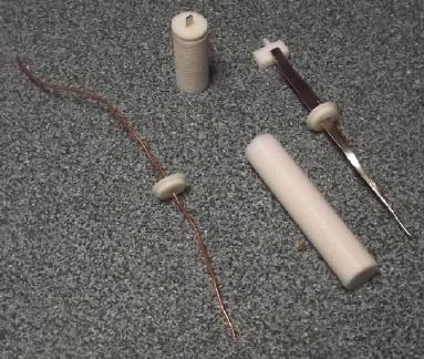 [17th] I made
another one 67mm tall, with minor adjustments to the cap
for a wider piece of metal and to the fit, and printing caps for both
"+" and "-". Somehow I'm amazed that with such a tall, thin shape it
doesn't come un-stuck from the bed during printing. The cap fitting
went from "too tight" to "too loose". I should have printed the two
caps different. The paper, after curling it around a "AAA" cell,
inserted fine.
[17th] I made
another one 67mm tall, with minor adjustments to the cap
for a wider piece of metal and to the fit, and printing caps for both
"+" and "-". Somehow I'm amazed that with such a tall, thin shape it
doesn't come un-stuck from the bed during printing. The cap fitting
went from "too tight" to "too loose". I should have printed the two
caps different. The paper, after curling it around a "AAA" cell,
inserted fine.
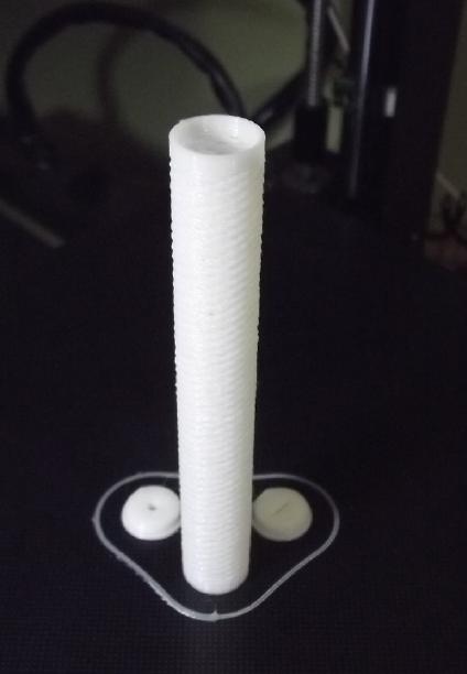 [18th] Third try, the full
100mm/4 inches, with two slightly different
caps sizes and the zinc side with a bigger center hole for a thicker
wire. Paper still stuffs in okay. "-" cap fits best. I tried another
with "retraction" off. It printed a bit faster but didn't look as clean.
[18th] Third try, the full
100mm/4 inches, with two slightly different
caps sizes and the zinc side with a bigger center hole for a thicker
wire. Paper still stuffs in okay. "-" cap fits best. I tried another
with "retraction" off. It printed a bit faster but didn't look as clean.
[19th] Well, those were all
done with PLA filament as tests. Since PLA
disintegrates in alkaline solution, I now have to print them in PVB or
else ABS. I haven't successfully printed ABS on this printer, only on
the old REPRAP that for some reason I can't get to work. (Hmm, I wonder
if it would work from an SD card instead of hooked to the computer?
I've never tried an SD card on that printer. It has no display - maybe
an SD card with only one .GCODE file on it will print that file?)
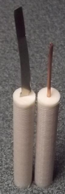 Anyway, so PVB
on the "AnyCubic I3 Mega"... They aren't
perfect - little spiderwebs of filament everywhere, esp. with the PVB.
But it never ceases to amaze me that the the tall, skinny cylinder
prints don't break off the bed and topple over.
Anyway, so PVB
on the "AnyCubic I3 Mega"... They aren't
perfect - little spiderwebs of filament everywhere, esp. with the PVB.
But it never ceases to amaze me that the the tall, skinny cylinder
prints don't break off the bed and topple over.
Since this seems (so far)
like it should work nicely, the
tedious part is going to be getting back into and re-doing the
chemistry. I'll have to work out a plan for getting the osmium dopant
and sodium dodecylbenzenesulfonate into the cylinders with the zinc. I
plan to use the Ovonics team's nickel mix from the late 1990s, as it
seems they worked it out really well and got the highest amp-hours per
kilogram of any. Dissolving the powders in acetone is a much simpler
means for combining them into epitaxial crystals than Ovonics' complex
processes.
But the biggest energy is in the zinc.
[20th] In the Ovonics patent, two groups of metal percentages in the
mixes are mentioned over and over as the "preferred embodiments".
Ni 93%
Co 5%
Ca 1%
Mg .5%
Zn .5%
The second one, only slightly different, seemed to have slightly better
overall results (and used the least cobalt):
Ni 95%
Co 3%
Ca 1%
Mg .5%
Zn .5%
So this, as far as I'm able to determine small quantities
in the mix, is what I will try next. Rather than the complex Ovonics
process for combining sulfates and other things to end up with oxides,
I'll be mixing them directly as
Ni(OH)2
Co(OH)2
CaO
MgO
ZnO,
all dissolved in acetone, which is thoroughly mixed then the acetone
evaporated, to produce the doped epitaxial crystalite nano-powder
material.
Hopefully this will yield a similar result. The acetone approach worked
well last winter, and is in fact the first technique I've tried that
has worked well. NiO is probably better than fluffy Ni(OH)2. When it is
wetted with water it will change back into the hydroxide, but it should
be more dense in the mix. The patent says their mix yields a higher tap
density than previously typical ones - let's help it. And my cobalt is
Co2O3.
NiO ---- 58.7 + 16.0 = 74.7
Co2O3 - (2*58.9 + 3*16.0) / 2 = 82.9
CaO ---- 40.1 + 16.0 = 56.1
MgO ---- 24.3 + 16.0 = 40.3
ZnO ---- 65.4 + 16.0 = 81.4
Doing the percents and rounding off to nearest .05 grams (my weigh
scale's finest):
NiO ----- 74.7 * .95 = 70.95 g
Co2O3 - 82.9 * .03 = 2.50 g
CaO ---- 56.1 * .01 = .55 g
MgO ---- 40.3 * .005 = .20 g
ZnO ---- 81.4 * .005 = .40 g
(Wow, they got some great improvements with pretty tiny percentages of
additives!)
That doesn't seem like much. I think I'll double it.
NiO - 141.9
Co2O3 - 5.0
CaO - 1.1
MgO - .4
ZnO - .8
I found I had everything except MgO. But for some reason I
had magnesium carbonate, MgCO3. On line I found it could be calcined:
heated until CO2 is driven off: MgCO3 + heat => MgO + CO2 (gas). A
wide
range of temperatures from 300 to 900°C were mentioned.
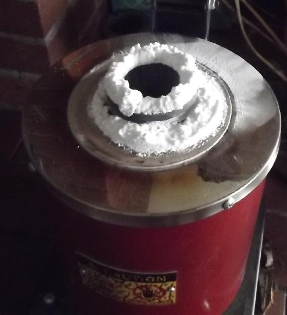 [21st] I picked 600°
for 20 minutes. That's 24.3 + 12.0 + 3*16
(MgCO3), to yield 24.3 + 16 (MgO). = 40.3/84.3 = .478. So 100 grams of
MgCO3 should yield 47.8 g of MgO. Measuring near that weight after
heating indicates it was successful.
[21st] I picked 600°
for 20 minutes. That's 24.3 + 12.0 + 3*16
(MgCO3), to yield 24.3 + 16 (MgO). = 40.3/84.3 = .478. So 100 grams of
MgCO3 should yield 47.8 g of MgO. Measuring near that weight after
heating indicates it was successful.
It was so light and fluffy that only 30 grams fit in the
crucible. So it should make 14.35 grams of oxide. A bunch fluffed out
the top of the crucible as the gas came off and a little of that got
spilled as I tried to scoop it into a container. I measured 14.2 grams,
which
seems awfully close.
[22nd] Having decided that the NiO I had
made from the Ni(OH)2 was
better, I found I only had 38 grams. Rather than do another batch in
the kiln now, I just went with that. (As I recall that too floated up
out of
the crucible like the MgO - ug.)
38/70.95=.5356 - about half a batch. (So much for a double batch! I'll
have to look through previous issues to find the oven temperature for
converting some more Ni(OH)2.)
NiO ----- 38 g
Co2O3 - 1.35 g
CaO ---- .30 g
MgO ---- .10 g
ZnO ---- .20 g
Weighing such small quantities I'll have to trust that the
proportions aren't hyper-critical. And after all the patent says "3%"
and ".5%", not "3.1%" and ".46%". In fact, in the patent the cobalt can
be 5% instead of 3% with only small changes to results. I got them
saying the exact figures above except for the nickel, for which I used
a 1 gram rez. scale and didn't get decimals.
In [yet another] video, in this one on recycling lithium
batteries they harped on about the cost of cobalt and lithium for
lithium batteries. Well, this much cobalt isn't going to add much to
the cell cost. (Of interest?: This Vancouver company didn't separate
back to raw
materials, but into a complete mix for making new cells, saving
processing steps over starting from freshly mined minerals - value
added!) The same video also said they precipitated the battery powder
out from the precursors very slowly to get fine grain sizes. They
showed some lovely SEM images of perfect little porous balls. I'll have
to pass on SEM images unless I can send samples and get someone to do
them for me.
I added acetone until the powders were a thick paste and
mixed them for a while with a fork. Then I set the lid on top with a
little crescent opening so the acetone would evaporate very slowly.
Dissolving in acetone and then letting it evaporate might
seem a wasteful process, but of course if it was commercial
production, the acetone vapor would be captured, condensed and reused
each time.
[26th] Days later it looked like cracked, dried mud and still smelled a
bit of acetone. I stirred it up into a fine gray powder. It didn't seem
to puff up into drifting dust in the air the way its precursors had.
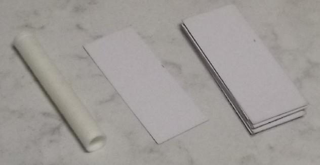 I
cut up a piece of watercolor paper, piled the pieces and soaked them in
toluene, twice. This treatment stops the nano-powders from seeping
through the paper.
I
cut up a piece of watercolor paper, piled the pieces and soaked them in
toluene, twice. This treatment stops the nano-powders from seeping
through the paper.
(I cut the paper the hard way: it rolls up easily top to
bottom but wants to fold up side to side.)
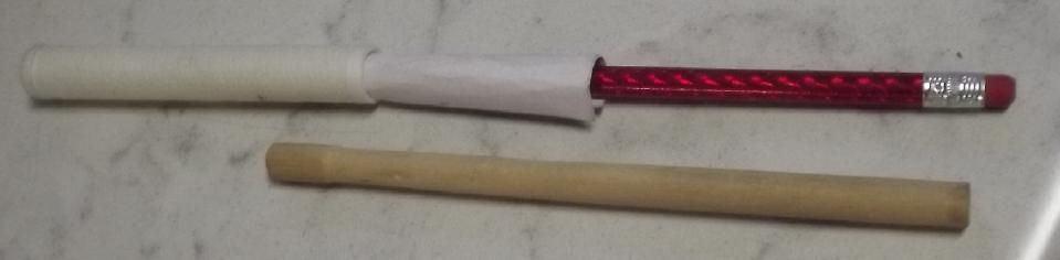 Putting a paper into a tube
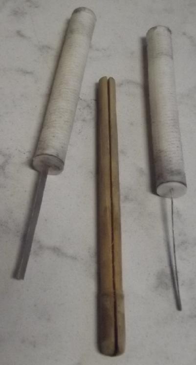 A
stick to tamp the powder down in the tube with the current
collector/terminal post sheet in the tube
A
stick to tamp the powder down in the tube with the current
collector/terminal post sheet in the tube
The stuffed
nickel hydroxide 'trodes,
caps 'glued' on with methylene chloride.
I had been wondering what to do about the negative side. A
copper wire center in zinc powder was simple, but what about the
treatments? The SDBS could be incorporated into the mix, or the
finished electrode could be dipped still dry into a solution of it
so that it would absorb in. Would it get through the paper into the
active mix? And SHOULD it, or does it just need to be in the paper?
Then there's the osmium dopant. It seems to me that needs to be a thin
layer at the surface of the zinc. No point infusing it into thick
separator paper.
And yet, it wouldn't go far incorporated into the electrode substance.
Osmium isn't cheap.
Finally I thought of painting it onto cellophane and
inserting a tube of doped cellophane inside the paper separator sheet.
At least the cellophane is thin and would be touching the outside of
the zinc substance. (I also thought of not having a paper inside the
plastic tube on the zinc side, which would also help the electrode
absorb the SDBS. But I think it needs it.)
[27th] In the actual mix would be zinc powders with .5% zirconium
silicate to raise the hydrogen overvoltage. I think my bags of zinc
powder and zinc flakes are too fine. I should get some coarser zinc
granules. The most practical thing would seem to be to take apart some
alkaline "D" cells, dilute out the KOH and use the zinc/zinc oxide
powders. After all, the mix in those was determined by commercial
battery makers. I'll add some of my own powder too.
[28th] I began to doubt my original plan of compacting the powder into
the electrode tubes and then ramming in a long, thin current collector
with a sharpened end. It would surely just bend, fold, spindle and
mutilate*. So I made dowels to stick into the tubes: one plain to push
the paper to the outside, one with a slit for the narrow stick of
cupro-nickel sheet metal current collector for positive electrodes and
one with a hole through the center for the copper wire in the negatives.
Now I can funnel in the dry powder, push the current
collector through to the bottom, and then tamp down the powder with the
appropriate dowel with the current collector in place. Refill and tamp
until it's full and compacted, then put the cap on.
The acetone smell being pretty much gone, I made two
positives. One took 5.20 grams of powder, the other 6.00. I'm not sure
why the 15% discrepancy. (The scale turned itself off while I was
working, but I think both numbers are right.)
And for the zinc side I
painted a little piece of cellophane with the osmium dopant, cut a
piece from that and put it into a papered electrode tube.
In the meantime I got out a jar that already had zinc
centers from old
alkaline "D" cells, diluted off the KOH and plucked some separator
papers out, leaving (I trust) a paste of zinc and zinc oxide powders
and
granules, which I set to dry on the woodstove.
[29th] The drycell zinc actually had a lot of fiber still in it and was
hard to break up. But I wonder if water wicking fiber inside the
electrode might not be an advantage? It should bring the electrolyte in
throughout the active material, leading to better utilization. unless
it reduces electrical conductivity too much.
I mixed up 40g of the above with 40g of fine zinc powder flakes
and .65g of zircon, poured some into an electrode tube, stuck a wire
in, tamped it down, and repeated until the tube was full of compacted
powder, then I put a cap on it. When everything was weighed there
seemed to be 14.25g of zinc. (No doubt some of it from the dry cells
was zinc oxide.) If it was all zinc, at 820 mAH/g that indicated 11685
mAH. 10 amp-hours from one tube! The nickel oxyhydroxide side - 2 tubes
- was 11.2g of powder. At 300 mAH/g that would be just 3360 mAH. It
would appear each zinc tube needs about five or six positive tubes
around it for a balanced cell. Yet the Ovonics formula seems much
better than older NiOOH mixes like Edison used, which evidently only
yielded about 90 mAH/g in practice. I guess it shows how much energy
zinc has!
I guess if I use the fourth tube it should be for a third
"+" electrode rather than a second zinc "-" one.
I note that there is quite a lot of not-active weight in
all this. The tube with paper was almost 5 grams and the #14 AWG copper
wire in the zinc one was 3-1/2g. Doubtless I should use #16 or finer.
The cupro-nickel sheet in the nickel side was 2 grams. Of course the
present objective is to make a prototype that works well rather than to
get the ultimate watt-hours per kilogram.
[30th] Awg... I finally found my fine (not flakes) zinc powder. Right
in the cupboard but not in the "zinc" box. It's been so long I had
forgotten that it was in a plastic bottle. Next time!
I glued the caps on the PVB plastic electrode tubes with
methylene chloride. Don't want them popping off in the cell!
Finally I mixed a tablespoon of sodium
dodecylbenzenesulfonate into a small drink bottle and filled it 3/4
with distilled water. It of course filled with suds and took a long
time to dissolve most of the lumps. Then I set the zinc 'trode (dry
powder) in it for a while to wick up the solution. This gell should
"adhere" and stay in, and prevent zinc ions from migrating out, the
bane of most zinc electrodes.
Charging & Initial Tests
All seemed ready... I mixed 300cc of water with 30 grams of potassium
chloride salt for electrolyte. With this weaker 10% solution the salt
dissolved quickly. The little drink bottle I put the electrode tubes
into took about 200cc. The cell started out around .4V and in 10
minutes rose by itself to about 1.125V and stayed near there. I put on
a charge of 2.1V thrugh 10Ω. [Start time 13:36PM] In a while I tried a
discharge. The numbers for voltage, current and resistance didn't add
up. I was using the Fluke meter on "300mA" range to measure battery
current in or out. Finally I measured the Fluke's 300mA shunt itself:
it was about 7.5Ω! That pretty much explained the discrepancies. I took
out the 10Ω resistor and used two 1Ω's, giving 9.5Ω. Charging current
went from under 30mA to about 45. For a 3+ amp-hour battery it should
take around 3 days to charge at that rate. As usual I didn't want to
charge faster for the initial "forming up" of the electrodes.
In a few hours it wasn't holding much voltage yet (1.3v),
and when a load like 10Ω was applied, it dropped below a volt and 90mA.
But there was an important achievement: With any load, whatever
voltage and current it managed to put out didn't start gradually
dropping off second by second: it held at that level as if it would put
out for hours before dying rather than minutes - amp-hours instead of
milliamp-minutes, just like a real battery.
The one I did also with acetone last winter had also
worked but sprung a leak some days into the testing. I gave up on
making flat cell bodies and decided to try this type, with perforated
tubes to hold the electrode powders compacted and "any old bottle" for
an unpressurized cell container. It's not the most compact or the
lightest or the highest current capacity, but seeing it's working
initially, I really have high hopes for it to continue to work. I'll
probably do that third "+" electrode and add it in for more current and
energy storage.
By the evening of December 1st the voltages seemed rather
low - they had gone up little over a whole day. It might sit at 1.9 V
on charge, but when the charge was removed it would quickly drop to
under 1.4V. I suppose that is up from a day ago at 1.3V. I expect it to
be over 1.6V, the "nominal" rating for nickel-zinc (in alkali). Short
circuit current is still just about 1/4 amp. OTOH, it doesn't fade but
continues to deliver 1/4 amp, or even go up a bit, over a minute or so.
Perhaps things are still "forming" inside the electrodes. We'll just
have to see what another day or two brings.
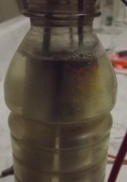 After a few
hours of charging the positive electrodes seemed to have some
orangy-yellow guck oozing out of them.
After a few
hours of charging the positive electrodes seemed to have some
orangy-yellow guck oozing out of them.
After three days, the voltages weren't rising like they
should, sitting at around 1.3V, and the cupro-nickel "+" terminals were
corroding off at the waterline. Sigh! That's where the corrosion seems
to take place. I bet within the electrode the interior of the
cupro-nickel metal is solid. Somehow the metal can't be exposed to air
and water.
Perhaps it could be painted otherwise protected above the
electrode, or I may be back to graphite materials for the positive
current collectors.
[Dec 6th] I drilled holes in the electrode tube caps and pulled out the
cupro-nickel lengths. I was wrong - they were surely only half the
width as when I put them in and thinner. So much for my cherished
belief that it wouldn't degrade in the positrode!
I stuck in fat graphite rods and got poor internal
connections. The cells would rise to the full charge voltage in minutes
and sit there drawing only a couple of milliamps. With the charge off,
they didn't drop back to 1.3V - that was apparently from the
cupro-nickel. They started at around 2 volts, but they did drop off
over the minutes since they were hardly being charged, and they would
run a load but dropped off in seconds rather than minutes.
Apparently graphite is the way to go, but I have to get
the current collectors in much more solid contact with the electrode
substance. It occurred to me that an answer to this is the usual dry
cell remedy: mix in graphite or conductive carbon black powder.
December will hold more news on this subject.
Electricity
Generation
My Solar Power System
The Usual Daily/Monthly/Yearly Log of Solar
Power Generated [and grid power consumed]
(All times are in PST: clock 48 minutes ahead of local sun
time, not
PDT which
is an hour and 48 minutes ahead. (DC) battery system power output
readings are reset to zero
daily (often just for LED lights, occasionally used with other loads:
Chevy Sprint electric car, inverters in power outages or other 36V
loads), while the
grid tied readings are cumulative.)
Daily Figures
Notes: House Main
meter (6 digits) accumulates. DC meter now
accumulates until [before] it loses precision (9.999 WH => 0010
KWH), then is
reset. House East and Cabin meters (4
digits) are reset to 0 when they get near 99.99 (which goes to "100.0")
- owing to loss of second decimal precision.
Km = Nissan Leaf electric car drove distance, then car was charged.
New Order of Daily Solar Readings (Beginning May 2022):
Date House, House, House, Cabin => Total KWH Solar [Notable
power
Uses (EV); Grid power meter@time] Sky/weather
Main
DC East
October
31st 810.05, 9.90, 9.64, 4.35 => 2.82 [55Km;
10357@17:30]
November
1st 811.18,9.97,10.48, 5.23 => 2.92 [10378@17:30]
2d 812.88, .06, 11.09, 5.96 =>
3.10 [10399@18:00]
3rd 813.85, .14, 11.60, 6.56 => 2.16 [90Km;
10437@22:30] Winter raininess sets in, heavy clouds.
4th ------ Oops! ------- =====> 2.00 (est)
[110Km; ??] Busy day
5th 815.68, .25, 12.49, 7.63 => 1.89 (est)
3.89 for TWO days ~2 KWH per day [10483@18:30]
6th 818.19, .28, 13.52, 8.80 => 4.80
[10501@17:30] Sun put in a brief appearance.
7th 819.27, .32, 14.34, 9.63 => 2.77
[10523@17:30]
8th 820.90, .39, 14.99, 10.35 => 3.07 [60Km;
10549@17:00]
9th --- Oops again! --- =====> 7.17 (est) [60Km; ??] Another
busy day
10th 825.79, .86, 17.77, 12.88 => 3.50 (est) 10.67 total for
TWO days: yesterday was much sunnier IIRC [90Km; 10595@17:00]
11th 827.80, 1.06, 19.17, 14.01 => 4.80 [55Km; 10634@17:00; 50Km]
12th 827.95, 1.14, 19.27, 14.17 => .49 [10669@17:00]
Gutter cleaning day (yetch).
13rd 831.34, 1.28, 21.28, 16.09 => 7.46 [10698@17:00] Sunny! I
left garage door open - the garage heat stayed ON several hours! (Hence
high grid power heating the great outdoors.)
14th 834.59, 1.39, 23.29, 17.09 => 6.37 [55Km; 10711@17:00] Nice day
until clouds & rain came @ 16:00. I turned on the 36V DC system in
the cabin, and half the power went for charging the battery, with no
meter on it (~1 KWH?). (& 290 AH - it's not charged yet.)
15th 837.87, 1.48, 24.91, 17.28 => 5.18 [50Km; 10739@17:00] Looks
like the cabin DC system is hogging all the power, so only 14
collectors are now being measured.
16th 839.52, 1.58, 25.89, 17.33 => 2.78 [10775@16:30]
17th 840.66, 1.68, 26.35, 17.35 => 1.72 [85Km; 10806@17:00]
18th 841.98, 1.77, 27.16, 17.74 => 2.61 [55Km; 10829@17:00]
19th 842.82, 1.95, 27.70, 17.77 => 1.58 [10847@17:00]
20th 843.03, 2.04, 27.83, 17.79 => .45 [10871@17:00] Nasty
storm - Southeaster!
21st 845.23, 2.17, 29.00, 17.86 => 3.57 [10886@17:30] Much quieter
22d 846.31, 2.22, 29.46, 18.43 => 2.16 [10913@17:00; 2.0 Km]
23rd 847.52, 2.27, 30.05, 18.59 => 2.01 [55Km; 10941@17:00]
24th 849.07, 2.33, 31.05, 18.63 => 2.65 [55Km; 10977@17:00]
25th 850.31, 2.43, 31.83, 19.38 => 2.87 [10997@20:30] (Turned cabin
DC off for the day, so cabin grid ties were working.)
26th 850.90, 2.47, 32.08, 19.42 => .92 [11011@17:30]
27th 851.01, 2.50, 32.15, 19.45 => .25 [11034@17:00] Just
clouds & drizzle - no storm.
28th 853.81, 2.65, 33.33, 19.97 => 4.65 [11057@17:00] A little sun!
29th 853.89, 2.95, 33.51, 20.18 => .87 [11094@17:00]
30th 855.75, 3.03, 33.99, 20.26 => 2.50 [11117@17:00]
December
1st 856.18, 3.08, 34.19, 20.29 => .71 [11144@17:00]
2d 858.62, 3.12, 35.07, 20.36 => 3.43 [11182@24:30]
3rd Oops ?, ?, 35.66, 20.41 => 1.93
(est) [?]
4th 859.87, 3.38, 35.68, 20.43 => .37 [11216@17:00]
Storm overnight, morning.... Power failure most of day. (freezer: DC)
5th 860.65, 3.62, 36.14, 20.50 => 1.55 [11235@17:00]
6th 863.21, 3.74, 37.44, 21.31 => 4.74 [11268@16:30] Sun but cold -
frost 'till noon.
7th 863.24, 3.78, 37.49, 21.33 => .13
[11293@17:00]
Chart of daily KWH from solar panels.
(Compare November 2023
(left) with October 2023 & with November 2022.)
Days of
__ KWH
|
November
2023
(18 then 14 C's)
|
October 2023
(18 collectors)
|
November 2022
(18 collectors)
|
0.xx
|
5
|
1
|
7
|
1.xx
|
3
|
2
|
1
|
2.xx
|
11
|
5
|
4
|
3.xx
|
4
|
1
|
5
|
4.xx
|
3
|
1
|
4
|
5.xx
|
1
|
|
1
|
6.xx
|
1
|
4
|
4
|
7.xx
|
2
|
4
|
2
|
8.xx
|
|
6
|
1
|
9.xx
|
|
1
|
1
|
10.xx
|
|
2
|
|
11.xx
|
|
2
|
|
12.xx
|
|
2
|
|
13.xx
|
|
|
|
14.xx
|
|
|
|
15.xx
|
|
|
|
16.xx
|
|
|
|
17.xx
|
|
|
|
Total KWH
for month
|
89.06
|
208.08
|
114.91
|
Km Driven
on Electricity
|
811.0 Km
(120KWH?)
|
1272.8 Km
(170 KWH?) |
793.1 Km
(120 KWH)? |
Things Noted - November 2023
* With the installation of the DC system in the cabin on the 15th, KWH
to the grid has dropped somewhat, and I presently have no means for
measuring the KWH of charge going into the 289AH, ~40V (11 KWH) battery.
Monthly Summaries: Solar Generated KWH [& Power used from
grid KWH]
As these tables are getting long, I'm not repeating the log of monthly
reports. The reports for the first four full years (March 2019 to
February 2023) may be found in TE
News
#177,
February
2023.
2023 - (House roof, lawn + DC + Cabin + Carport, Pole) Solar
Jan KWH: 40.57 + 3.06 + 28.31 + 21.85 = 93.79 Solar [grid: 1163; car
(very rough estimates): 130]
Feb KWH: 59.19 + 2.70 + 38.10 + 32.47 = 132.46 Solar [grid: 1079; car:
110]
(Four years of solar!)
Mar KWH: 149.49 + 2.72 + 53.85 + 92.08 = 298.14 Solar
[grid: 981; car:
140]
Apr KWH: 176.57 + 2.71 + 121.21 + 108.34 = 408.83 [grid: 676; car: 160]
"Lawn" collectors moved to South
"Wall"
May KWH:266.04 + 2.04 + 194.13 + 180.31 = 642.52 [grid: 500; car: 175]
Jun KWH: 237.55 + 3.70 + 172.56 + 126.31 = 540.12 [grid: 464; car: 190]
July KWH:236.99 + 1.95 + 169.16 + 155.21 = 563.31 [grid: 343; car: 180]
Aug KWH:223.61 + 1.78 + 158.31 + 134.40 = 518.00 [grid: 305; car: 130]
Sep KWH:124.33 + 2.33 + 92.76 + 76.23 = 295.65 [grid:
501; car: 150]
Oct KWH: 94.26 + 2.70 + 55.01 + 56.11 =
208.08 [grid: 842; car: 170]
Nov KWH: 45.70 + 3.10 + 24.35 + 15.91
= 89.06 [grid: 760; car: 120]
Annual Totals
1. March 2019-Feb. 2020: 2196.15 KWH Solar [used 7927 KWH
from grid]
2. March 2020-Feb. 2021: 2069.82 KWH Solar [used 11294 KWH from grid]
(More electric heat - BR, Trailer & Perry's RV)
3. March 2021-Feb. 2022: 2063.05 KWH Solar [used 10977 KWH from grid]
4a. March 2022-August 2022: in (the best) 6 months, about 2725 KWH
solar - more than in any previous entire year!
4. March2022-Feb. 2023: 3793.37 KWH Solar [used 12038 KWH from grid]
Money Saved or Earned - @ 12¢ [All BC residential elec.
rate] ; @
50¢ [2018 cost of diesel fuel to BC Hydro] ; @ 1$ per KWH [actual
total
cost to BC Hydro
in 2022 according to an employee]:
1. 263.42$ ; 1097.58$ ; 2196.15$
2. 248.38$ ; 1034.91$ ; 2069.82$
3. 247.57$ ; 1031.53$ ; 2063.05$
4. 455.20$ ; 1896.69$ ; 3793.37$
It can be seen that the benefit to the society as a whole
on Haida Gwaii from solar power installations is much greater than the
cost savings to the individual user of electricity, thanks to the heavy
subsidization of our power
owing to the BC government policy of having the same power rate across
the entire province regardless of the cost of production. And it can be
insurance: With some
extra equipment and a battery, sufficient solar can deliver essential
power in
electrical outages however long. (Feb 28th 2023: And it's probably well
over 1$/KWH by now the way inflation of diesel fuel and other costs is
running.)
http://www.TurquoiseEnergy.com
Haida Gwaii, BC Canada