Turquoise Energy News Report #190
Covering
Research & Development Activities of March 2024
(Posted April 12th 2024)
Lawnhill BC Canada - by Craig Carmichael
[CraigXC at Post dot com]
www.TurquoiseEnergy.com
= www.ElectricCaik.com
= www.ElectricHubcap.com
Month In "Brief"
(Project Summaries etc.)
-
"Everlasting" Cu-Zn
Battery Development - Zinc-Air Batteries for Aircraft! -
Open Loop Air Heat Pumping - Cabin Construction - Gardening
In
Passing
(Miscellaneous topics, editorial comments & opinionated rants)
* More on Tinnitus & AC Power: Beanie & Pillowcase; EMF
Meters; Car Shields - Scattered
Thots (DST Gripes etc) - ESD
- Detailed
Project Reports
-
Electric
Transport - Electric Hubcap Motor Systems (No reports)
Other "Green"
& Electric Equipment Projects
* Open Loop Air Heat Pumping
("OLAHP")
Electricity Storage:
Batteries
* Copper-Zinc cells: Experiments, Designs...
Electricity Generation
* My Solar Power System: - The Usual Latest Daily/Monthly
Solar Production log et cetera - Monthly/Annual Summaries,
Estimates, Notes
"Everlasting" Cu-Zn
Battery Development:
 Once again I
worked mostly on battery research and experiments - a solid five months
now and headed for six with April. I've long been sure that fantastic,
simple, cheap and high energy everlasting battery designs are possible.
They have eluded everyone so far, but at long last I feel I'm close to
having one. It sure takes time away from other projects, but I
persevere. And after all Edison did [at least] over 30 years of battery
research before he came up with nickel-iron alkaline cells, which were
much the best rechargeable batteries up to that time.
Once again I
worked mostly on battery research and experiments - a solid five months
now and headed for six with April. I've long been sure that fantastic,
simple, cheap and high energy everlasting battery designs are possible.
They have eluded everyone so far, but at long last I feel I'm close to
having one. It sure takes time away from other projects, but I
persevere. And after all Edison did [at least] over 30 years of battery
research before he came up with nickel-iron alkaline cells, which were
much the best rechargeable batteries up to that time.
Over March I had better success with a long, long nagging
problem: apparently all my symptoms are caused by "zinc oxide
passivation"
where migrated ZnO doesn't quite connect and recharge, but lodges in
all the pores at surface of the electrode, blocking the electrolyte and
"smothering" the electrode. As the cell discharges the output voltage
drops and drops not because it's very far discharged, but because of
increasing blockage. And this gets worse and worse without ever a full
recovery by recharging.
Now I still wasn't getting satisfactory performance, but
significantly it stayed the same day after day and didn't keep getting
worse.
The main reason for the improving picture is that now I
have a glimmering of what the problem is. Solutions (technical or
societal) aren't very likely from seeing the symptoms but without
understanding their root cause. I added 10% sodium sulfate to
the electrolyte, and I upped the pH to 13 or 14 (higher than
I wanted and probably higher than necessary - but whatever works) with
7.5% potassium hydroxide so that migratory zincate ions can
(presumably) form. I'm assuming the osmium doping helps the solid ZnO
at the surface to turn into dissolved Zn(OH)4- ions and go back into
the electrode as the cell charges.
As I understand it, during
discharge [in alkaline solution] zincate ions form up
to their solubility limit, which is not high. When that is reached, as
more zinc continues
to be oxidized, excess zincate particles (wherever they are) turn into
the oxide, ZnO. During charge, zinc oxide particles connected to the
electrode and zincate ions when they touch it are turned back into zinc
metal in the electrode. As these zincate particles disappear the
concentration drops, making way for more oxide to dissolve into
zincate - if it will. I think it's the osmium catalyst that helps turn
disconnected -
passivated - zinc oxide back into zincate ions as the concentration
reduces. Herein, at last, seems like a plausible theory of how a
rechargeable zinc
electrode can work, given the strong penchant for
passivation of zinc oxide.
I had wondered if a thin layer of osmium on
the separator was really enough when "the surface" of the powder
electrode is really whatever spaces the electrolyte reaches into, but
just now as I write this, I think that as the zincate ions connect to
the active electrode and charge back to zinc metal, the active
electrode thickens and pushes the passivated ZnO layers out toward the
osmium 'film'. So during charge the outer edge of the passivated oxide
keeps getting converted to zincate, which wanders into the electrode
and charges, sending the remaining ZnO out to the osmium, and this
process continues until the oxide is all converted back into zinc. In a
sense this makes it a "flow" battery, but the "flow" is inside the
mostly solid electrode. Anyway that's my new theory of operation. It
should also have very high potential zinc utilization, perhaps
approaching 100%: 820 amp-hours or just over a kilowatt-hour of energy
per kilogram of zinc. (An equal weight of copper with almost the same
amp-hours for a cell that might be rated 1.1 volts, has low voltage and
adds little to the energy, but two electrodes are necessary so we're
down at most to 500 WH/Kg, less with the non-contributing components.
Other positive electrodes - besides weightless "air", which has its own
challenges - contribute less by weight and volume overall.)
With the SDBS blocking all passage of zincate across
electrodes and zirconium silicate raising the hydrogen generation
voltage, it solves all zinc's four problems: (1) dendrites, (2)
hydrogen generation, (3) amalgamation of zinc particles and shape
changes of the electrode (it's continually shifting, amalgamating and
dissolving!) and (4) passivation. And now I realize I need to get the
acetaldehyde/osmium layer to be right on the surface of the
separator sheet. If I have it right, that should certainly make for a
"forever" working negative electrode.
(BTW Both "sulfonate" and a "heavy metal" layer are in accord
with techniques noted in the 2017 Zinc-Air
Battery paper that have been tried or conceived to potentially solve
zinc's
problems.)
My latest cell in March performed poorly but continued to
work about the same and
even improve some over 2-1/2 weeks. Highest currents (short circuit,
charge current after severe discharge) approached an amp, which is
the target. But the thin separator, thin nonwoven PP fabric ironed onto
parchment paper, eventually let dendrites through and there was more
and more leakage current. So I've gone back to toluene treated thick
watercolor paper.
Earlier I noticed on one separator sheet under the
microscope that the osmium powder was spread rather thinly and
unevenly, perhaps explaining why it doesn't work better. What I will
try next is to make a new pair of electrodes and this time use new
acetaldehyde that I've just bought to replace what I made myself in
~2011, and add osmium powder to it more generously. (That will probably
finish off my ~2011 one gram vial of fine Os powder.) On opening the
acetaldehyde, I note that I haven't smelled that forgotten 'flowery'
aroma in years, which says that my old acetaldehyde has been long since
diluted to nothing by adding too much water.
As we head into April I'm thinking of trying sheets of
copper coated zinc and sheets of cupro-nickel again instead of powder
electrodes. I can't infuse the dopant through a zinc powder electrode
without using a crazy amount of rare osmium, so zinc sheets may work
better because I only need to paint the flat surface, rather than the
effective surface being spread through the whole electrode. For the
plus, I had thought the cupro-nickel sheets worked great at first but
deteriorated, but it was probably the zinc that was deteriorating and
CuNi sheets continue to work fine.
Powder electrodes may seem to provide a lot more surface area to react,
but thin sheets have more surface interaction area with many more thin
electrodes in the same space, which should also multiply current
capacity.
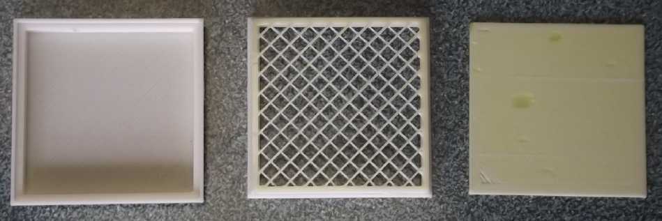
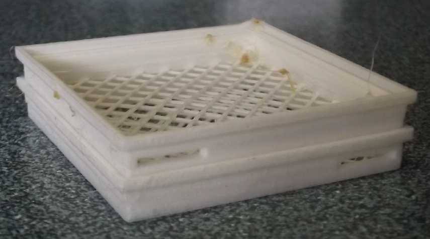
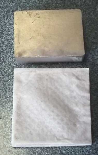
 On the construction side
I started making "stacking tray" electrodes, still 50x50x6mm I.D. with
the separator sheet at the bottom of each tray. These are loaded with
exact weights of powder (and the current collector/terminal tab piece)
via the open top and then the next electrode is stacked and glued on
top, alternating Cu-Zn-Cu-Zn... The bottom tray has a solid bottom and
a solid top sheet glues over the top one. This is the compact but easy
to assemble and has just one exact size separator paper between each
pair. Then the stack is turned sideways with the current collectors.
That's the idea. I only stacked two (and filled the rest of the box
with spacers) because they still weren't working great.
On the construction side
I started making "stacking tray" electrodes, still 50x50x6mm I.D. with
the separator sheet at the bottom of each tray. These are loaded with
exact weights of powder (and the current collector/terminal tab piece)
via the open top and then the next electrode is stacked and glued on
top, alternating Cu-Zn-Cu-Zn... The bottom tray has a solid bottom and
a solid top sheet glues over the top one. This is the compact but easy
to assemble and has just one exact size separator paper between each
pair. Then the stack is turned sideways with the current collectors.
That's the idea. I only stacked two (and filled the rest of the box
with spacers) because they still weren't working great.
I also tried ironing the PP fabric-parchment paper
underneath instead of placing it inside. That way no inner lip (or
really, really exact fit) was needed in the tray design.
With 50x50mm area minus the crosshatch and any inside lip,
in figure it's only about 20 sq.cm of interface area between
electrodes. If the target is 50 mA/sq.cm maximum current, that's about
an amp of current between each two trays - or two amps per tray except
the end ones.
I don't think I can iron on PP fabric with thick
watercolor paper, so the papers will have to go inside.
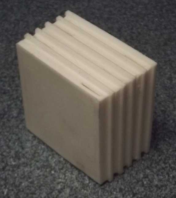 Stack of five trays (there the
PVB filament ran
out)
Stack of five trays (there the
PVB filament ran
out)
In making these I ran out of PVB 3D printer filament and
tried to use ABS. ('Easiest to use' PLA disintegrates in alkali.) After
much frustration (including damp filament that just plain wouldn't work
until dried by the woodstove for a week or two) kept I wondering why it
wouldn't print nicely like with the old RepRap 3D printer, and finally
I realized it: the old Pronterface slicer that I used with the old
printer did .4mm layers of plastic, but Cura does .2 or .3mm. Not only
does it take much longer to print than the old way, but the first layer
of ABS is thin enough to bend and warp, easily warping the print and
coming un-stuck form the bed during printing. I hope for better results
next time by changing the settings. (I think this printer can
do .4mm vertical layers. But it might depend on nozzle diameter.)
 Trying to keep the 3D printer bed
warm with a
400W heater and cardboard.
Trying to keep the 3D printer bed
warm with a
400W heater and cardboard.
It didn't seem to help much.
 The three ABS prints that worked.
But the bottoms of the corners are curled up.
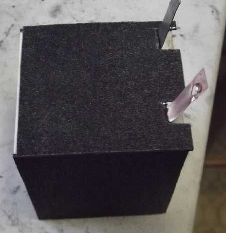
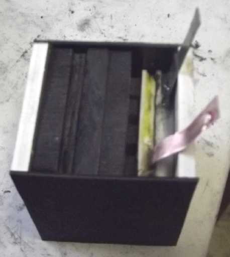 I also made a
new cell housing, a little wider to hold the extra lip of the trays and
taller to hold terminal tabs inside, all bent over to make the just two
external connections from rows of multiple trays.
I also made a
new cell housing, a little wider to hold the extra lip of the trays and
taller to hold terminal tabs inside, all bent over to make the just two
external connections from rows of multiple trays.
(If this was full with eight trays, each holding about 10
grams of zinc or copper, it might be 30 amp-hours, ~1.1V, 33
watt-hours, in just 150(?) grams.)
Zinc-Air Batteries for Aircraft?
I had sort of cast off metal-air cells as not very
practical. The trouble with air electrodes is that they are exposed to
the environment. Not only O2 but CO2 enters, and CO2 gradually
deteriorates the alkaline electrolyte and the cell, turning hydroxides
into carbonates. (Salt electrolyte with only a little potassium
hydroxide added might be more immune?) H2O too can exit - or enter - so
the cell's delicate balance of hydration changes.
Better then to use a positive electrode like copper and
more or less seal the cell? In general I think so, but aircraft is one
application where cutting the weight of a battery in half again is
probably valuable enough to warrant using cells that need some "looking
after" and even occasional replacement. The much improved flying time
and range that would be provided by super lightweight zinc-air
batteries could open up whole new areas for adoption of electric
aircraft.
Open Loop Air Heat Pumping (OLAHP)
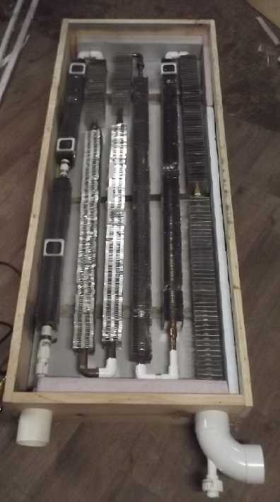 I finished
piping and insulating the indoor-outdoor heat exchanger. I brought it
into the house and connected the cold air intake through an existing
hole in the house wall (from the 2020 experiments). But there it sat.
Maybe it'll be ready by summer?
I finished
piping and insulating the indoor-outdoor heat exchanger. I brought it
into the house and connected the cold air intake through an existing
hole in the house wall (from the 2020 experiments). But there it sat.
Maybe it'll be ready by summer?
Cabin Construction
Work on this consisted mainly of just two things
1) getting the garage door from raw styrene foam to covered with the
galvanized sheet metal from the refuse station.
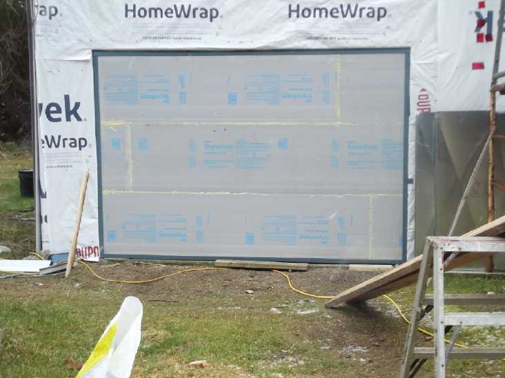 Start of month
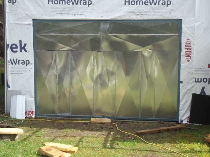 End of month
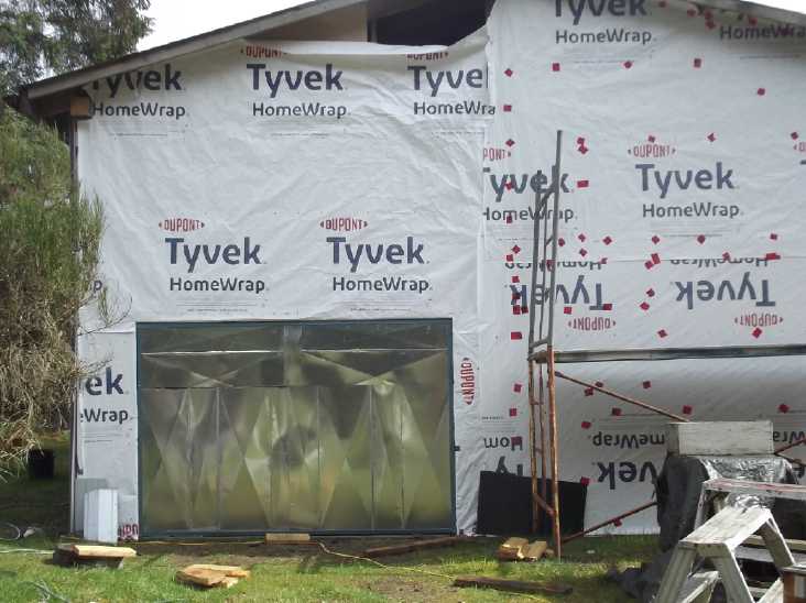 Broader perspective
Unfortunately the door weighed about three times as much
with the metal on it as without. When I went to pick it up and put it
in place it took me by surprise and I once again re-injured my "tennis
elbow". Yikes! There are all kinds of things I need to do that I can't
until it heals, and I keep re-hurting it. 10 months now? My right hand
is weaker from three separate injuries of long ago and also being my
non-dominant hand, it can't take up much of the slack. Longer term I
can only live on the acreage if I'm able bodied!
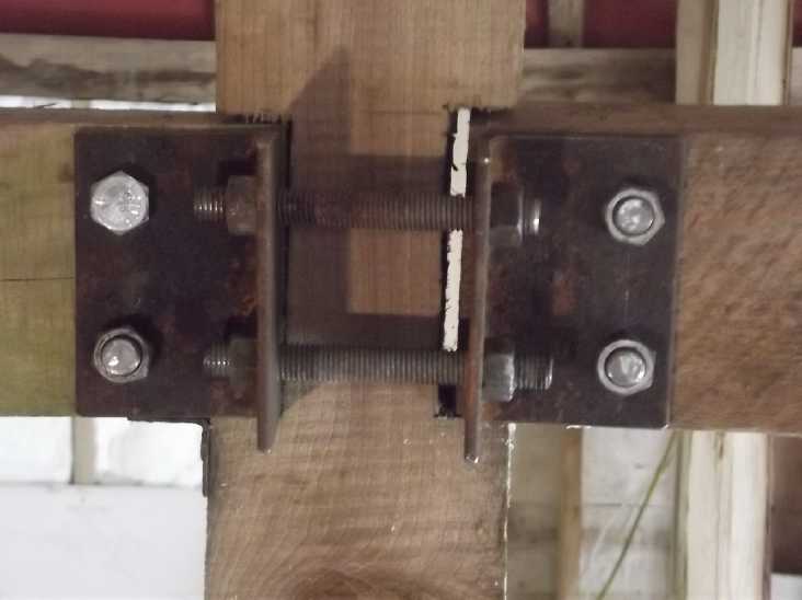 2) The center beam between
the long walls is made of two pieces with a "temporary?" post between.
(It doesn't go to the roof.) I noticed the beam pieces were pulling
apart, bending a light angle iron piece (now removed) originally
holding them to
the post. The roof is pushing the walls apart and will start to sag in
the middle. In ultimate potential, things could collapse. After finding
a very heavy piece of angle iron at the refuse station, I cut and
drilled two pieces, then drilled holes through the beams, put the
pieces on with 3/4 inch bolts, removed the bent piece, and started
tightening to pull it back
together.
2) The center beam between
the long walls is made of two pieces with a "temporary?" post between.
(It doesn't go to the roof.) I noticed the beam pieces were pulling
apart, bending a light angle iron piece (now removed) originally
holding them to
the post. The roof is pushing the walls apart and will start to sag in
the middle. In ultimate potential, things could collapse. After finding
a very heavy piece of angle iron at the refuse station, I cut and
drilled two pieces, then drilled holes through the beams, put the
pieces on with 3/4 inch bolts, removed the bent piece, and started
tightening to pull it back
together.
This had the effect of pushing the pieces of the beam
sideways since the other side had no tensioner. So I've cut two more
pieces for the other side of the beams, but the 6 inch long bolt holes
don't
quite line up. Somehow I have to considerably file out two of the holes
in the metal without wrecking my elbow again. My milling machine won't
run (I'm sure it doesn't like being in the unheated shop) and I'm sure
I would also hurt my elbow again if I tried to drag it into the house.
Without wanting to complain, my elbow is turning into a more and more
serious problem.
Gardening
I bought several "exotic" varieties of seed potatos:
Violet Queens (purple throughout), Russian Blue (mottled purple/white),
Warba (?) and Huckleberry Gold (yellow flesh). This on top of my usual
three varieties to replant of white, red and purple with white eyes
(all with white flesh). I had bought the violet, fingerling, and yukon
gold, before, but I was planting them all randomly and either lost them
in the heavy freeze in February 2023 or ate them all.
This time variety each got its own row, but I found I had
bought too many. I seemed to have nowhere to plant my own old potatos
from last year!
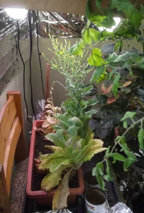 I didn't dump
the lettuce, planted in September, that had got tough and bitter after
all winter under the
LED light. I kept watering it and now it was flowering to go
to seed.
I didn't dump
the lettuce, planted in September, that had got tough and bitter after
all winter under the
LED light. I kept watering it and now it was flowering to go
to seed.
 After some months the ~50
'beans' growing on a potted coffee plant were ripening. (Someday I'll
have enough beans to roast and grind for a pot of coffee?)
After some months the ~50
'beans' growing on a potted coffee plant were ripening. (Someday I'll
have enough beans to roast and grind for a pot of coffee?)
...and a lot of the lower leaves were falling off.
Probably from the LED lighting coming from above and not reaching the
lower branches. They're in the south wall bay window and the LED
lighting was intended to be "supplemental", but there's not much
outdoor light in winter.
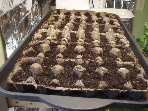 Per a youtube video (Genius
way to plant carrots) I seeded carrots on a cloth in a plastic
container and when they sprouted I used tweezers to plant one in each
place in cardboard egg cartons, with the bottom punched out so the root
could grow freely. That way presumably they would all be sprouted (no
"duds") and I wouldn't have to thin and weed them. (They were there but
hardly show in the foto.) Carrot roots grow fast, so I put them in the
garden after a few more days. But there seemed to be a lot of empty
spots by then, and I probably put them in too early.
Per a youtube video (Genius
way to plant carrots) I seeded carrots on a cloth in a plastic
container and when they sprouted I used tweezers to plant one in each
place in cardboard egg cartons, with the bottom punched out so the root
could grow freely. That way presumably they would all be sprouted (no
"duds") and I wouldn't have to thin and weed them. (They were there but
hardly show in the foto.) Carrot roots grow fast, so I put them in the
garden after a few more days. But there seemed to be a lot of empty
spots by then, and I probably put them in too early.
I should have been potting tomatos and peppers in
March but didn't get to them.
I have also been reluctant to go out in the gardens and
prepare beds for fear of wrecking my elbow again.
In
Passing
(Miscellaneous topics, editorial comments & opinionated
rants)
More
on
Tinnitus
&
AC Power: Beanie & Pillowcase; Car Shields;
EMF Meter
About the start of March the conductive tuque and
pillowcase, with silver woven into the fabric to help block electric
fields, arrived from "LessEMF.com". (Later Perry found a Canadian
seller of similar goods, SafeLivingTechnologies.com) I started wearing
the tuque all day. At night I put the "pillowcase" on top of my pillow,
lay my head on one end, and folded the other end over my head. on top
of having grounded the metal house roof at multiple points. In a few
days I could hear that things were changing. The loud piercing tone
sort of "broke up" into on and off tones and high frequency noise.
But I was disappointed that with all this the ringing
still didn't really seem to be fading away. On the 13th I tried
checking the volume of the ringing in my ears with the on-line signal
generator and audio meter again. Again it's pretty hard to tell, but I
had the impression it was down maybe around 3 dB from 42 to 39 dB,
which is actually half power. (-6 dB is half perceived sound level.)
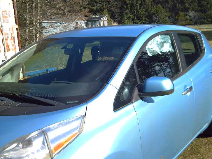 As driving on
the highway (right under the 14,400 VAC power lines all the way) seems
to notably aggravate it, I folded and pinned a piece of alume foil over
the sun visor and always keep it pulled down. That way the power line
was much less visible through the windshield. I think that helped a
bit, too. Then I put a smaller piece at the top of the side window for
when the power lines were to the left of the car. (I hardly ever drive
with the windows open anyway as it makes a nasty low frequency pressure
vibration on the highway. If I open one a bit, it's the rear right.) I
was thinking of putting some cardboard on the outside so sunlight
wouldn't flash in peoples' eyes, but the window automaticly opens all
the way with a push on the lever, and I soon accidently crunched the
foil. It will inevitably happen again. No point getting more elaborate,
then!
As driving on
the highway (right under the 14,400 VAC power lines all the way) seems
to notably aggravate it, I folded and pinned a piece of alume foil over
the sun visor and always keep it pulled down. That way the power line
was much less visible through the windshield. I think that helped a
bit, too. Then I put a smaller piece at the top of the side window for
when the power lines were to the left of the car. (I hardly ever drive
with the windows open anyway as it makes a nasty low frequency pressure
vibration on the highway. If I open one a bit, it's the rear right.) I
was thinking of putting some cardboard on the outside so sunlight
wouldn't flash in peoples' eyes, but the window automaticly opens all
the way with a push on the lever, and I soon accidently crunched the
foil. It will inevitably happen again. No point getting more elaborate,
then!
A decade ago I had noticed an increase in my tinnitus on
the city streets very soon after I started driving my first electric
car, the silent, converted Mazda RX7 EV. I had wondered if it was
something electrical in the PWM motor drive circuits (in spite of the
unit being in a metal housing behind the metal firewall), but obviously
it was the power line fields coming right through the windows, never
really noticed before when driving noisy petroleum vehicles.
As the weather warmed I
started gardening and other outside work. The first day I was out I was
using the angle grinder, so I took my conductive threads tuque off and
put on safety glasses and ear protector "headset". After a while the
ringing in my ears was returning from "high frequency noise" to being a
loud "whistle" again. Of course for short periods I was also making
actual loud noise which can cause temporary tinnitus, but I did have
good ear protection on. I start to realize that not only the tuque but
having grounded the metal roof of my house at several points (as well
as having covered one wall with 2" mesh chicken wire) has been really
beneficial. It's been quieter but not by any means going away. (It's
too bad I can't ground the tuque.) Now being outdoors more it's getting
worse again. The house and my whole yard are definitely much too close
to the power lines. I have 5 acres, but only the part near the highway
is cleared - the rest is trees. (Chicken wire on the house east wall
facing the power lines is probably the best next step. And get the
grounded metal roof & sides cabin (with grounded chicken wire over
the windows) finished so I can occupy it much of the time. I found one
more roll of old 2" mesh chicken wire and brought it out front. But the
"CLACK" of the staple gun, or nailing staples, will re-injure my tennis
elbow. Now what? Screw it on with short screws and the electric drill,
I suppose.)
On April 3rd, after having had the conductive pillowcase
folded over my head pretty much all night (I think), the ringing was
"the usual" very loud with each heartbeat, but much quieter in between.
But before I got up it had quit being louder then too. Then I get up
and feed the chickens in the front yard and being in the kitchen just
inside from there, and it gets worse again fairly rapidly and stays
that way (even with the beanie on). It just shows how variable it can
be, how strong the EMF from the power lines is, and how long (at least
for me) it takes to quiet down.
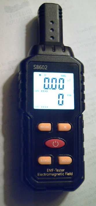 Also this day,
Matt had ordered and received two EMF meters, both "S8602" (from
"Temu"?). Since he offered and they were only 15$ I bought one of them
from him. In my front yard nearest the power line it was reading
between 50 and 100 volts per meter, flashing its LEDs, beeping and
displaying "Harmful". If I held it up with my arm stretched out, it
read upwards of 200 V/m and only somewhat higher standing on a chair
with outstretched arm. (I saw a "238" at one point.) Perhaps I should
mention that there's a steep ten foot bank from the highway and so the
front yard is "ten feet up the power poles" - about 1/3 of the way up -
already at ground level.
Also this day,
Matt had ordered and received two EMF meters, both "S8602" (from
"Temu"?). Since he offered and they were only 15$ I bought one of them
from him. In my front yard nearest the power line it was reading
between 50 and 100 volts per meter, flashing its LEDs, beeping and
displaying "Harmful". If I held it up with my arm stretched out, it
read upwards of 200 V/m and only somewhat higher standing on a chair
with outstretched arm. (I saw a "238" at one point.) Perhaps I should
mention that there's a steep ten foot bank from the highway and so the
front yard is "ten feet up the power poles" - about 1/3 of the way up -
already at ground level.
I remember a few times my tinnitus was just so bad
I was lying in bed awake. That was probably when I was working on the
carport, especially the roof, and later when I put solar panels up
there. I hadn't done anything that was noisy and I just couldn't
understand why it was so bad - not that I understood even having it at
all. Now I went up and measured. Sure enough, it was over 20 V/m at the
west side and around 100, flashing and beeping "harmful" at the east
end by the solar panels. The power line is more horizontal than
vertical distance from there, and maybe 30 feet away.
Indoors it got above 50 V/m right by power outlets with
wires plugged in. By the wall & windows facing the highway I
couldn't get a steady reading. It mostly sat at "0" but as I moved it
around it would jump to values in the 30s or 40s and even start beeping
"harmful" occasionally.
Standing on the highway, at head level it was around 55
and beeping on the powerline side and 30 on the far side. That
certainly explains why driving anywhere notably aggravates my tinnitus.
However, in spite of being advertised as "0 to 1000 volts
per meter", whenever the reading falls below 20 V/m it just stops and
reads 0. (and says "Safe") That's most places. To determine how loudly
my ears will eventually be ringing I'm sure I need to know whether it's
1 V/m or 10 V/m, so this particular meter is pretty useless. For no
apparent reason it will only tell you about the worst extremes.
But it gave me the idea. I checked out "EMF Meter" on
AliExpress.com and found one that showed "005.00 V/m" in the pictures
for around 27$. That should be much better, so I ordered it. The
cheaper EMF meters from popular outlets are much more affordable than
those from LessEMF and SafeLivingTechnologies.
Grounding roofs and putting up grounded chicken wire on
wall is helping, but a meter would be able to quantify the improvements
and to point out the next worst area to tackle.
Going beyond into April, Rolph sent me a
link to a youtube video Electrosmog
Radiation - Effects on the VDR (and beyond) by DrTevorMarshal. It
was a lecture about radiative effects including on the immune system
and bacteria within the body. Much of it was biology far from my
knowledge base, but one special take-away for me was that the cloths
with copper and silver in them aren't very effective at low
frequencies, ie, AC power frequencies. I was really figuring as much
from the disappointingly little improvement the tuque seemed to be
making. He showed a slide of some Faraday cages, one of conducting
cloth and others of "special aluminum foil" sheets, all hung from the
ceiling and completely covering beds. He said the alume ones were much
better. (Measuring the tuque, resistances can be measured - sometimes -
between very nearby points. We really need a cloth that measures pretty
much a short circuit across any two points, from one end to the other.
I haven't seen anything like that.)
Somehow I never thought of metallic "walls" hung from
horizontal sticks, which are hung by wires from the ceiling around the
bed. The idea seems promising, but it would take a lot of tinfoil
(which would soon get crinkled and wrecked)!
Now I see another video (Is Your DNA an EMF Antenna?
by ScottiesTech.Info - youtube) where the presenter says over 1000
studies over the decades show that electricity has negative effects on
our health. He describes a study indicating that our DNA molecules are
"fractal antennas" which are affected by electric fields, which
register as stresses. He also mentions a book, The Invisible
Rainbow, A history of Electricity and Life wherein the author,
Arthur Firstenberg, relates the incidences of new electric
infrastructure development to outbreaks of new diseases or ailments.
Which suddenly reminds me... When I was 3 or 4 (1958 or
'59), my parents moved me from the back bedroom to a front one. The
upstairs front was probably about level with the trolley bus wires, at
maybe 16 meters distance. (On Google streetviews, the house looks the
same but the trolley lines and poles were removed 1968-69 when we were
gone for a year. I can't remember if there were power lines 10 meters
from my window before or not.) I started complaining about persistent
ringing in my ears when I was 5 or 6. (I wonder what the voltage of the
trolley wires was?)
I'm liking adoption of 36-40 volts DC as the prime power
source for homes more and more!
Scattered
Thots
* There are atomic clocks with precision to picoseconds. This exact
time is available on the internet to the whole world. So how is it that
here on Haida Gwaii our clocks have once again moved from nearly an
hour
ahead of the actual time to two hours ahead?
* The increasingly protracted length of so-called "daylight savings
time" ("DST") or as I call it "get up in the dark time", is another
example of legislatures not being qualified or not giving sufficient
study to the subject in passing the laws they do. I remember when it
was lengthened - for about the third time - to be well over half the
year. A US
congressman argued passionately that we needed to extend it "to save
energy". AFAIK he presented no evidence to make his case, just
implicitly
assumed that somehow forcing everyone to get up earlier would somehow
"save
energy". The only statistical evidence we actually have comes from a
couple of US states that didn't adopt DST with the rest until the
federal government mandated it. Their annual energy consumption rose
marginally when they started using DST. Obviously he was ignorant of
these statistics. Surely he had resources and staff who could have
looked them up if he had asked. And nobody else in congress challenged
him - none of them knew or bothered to check either. The whole US
congress
passed the bill in ignorance, and Canada followed suit like robots!
Thus the change achieved the opposite of its intended
purpose. Statistics probably show slightly increased energy consumption
if anything, if anyone has ever investigated - as should have been done
to follow up on the new rule. It has only worked harm, most notably in
accident statistics mostly in the first week of people having to get up
before dawn again even as the days lengthen, and go to work an hour
earlier than usual. (And sleep deprivation is statisticly worst at the
western ends of each time zone, where the sun goes down almost an hour
later than at the eastern ends so people stay up later, but are
expected to get up and go to work with the clock.) Congress should have
soon retracted
this legislation with red faces. It never happens, does it? Us "night
owls" end
up "burning the candle at both ends" year after year. Not being on any
politician's special agenda now, this mistake has never been addressed
and
is still with us, now for many years.
(No doubt I've said all this before.)
We can all screw up at any time of the day, but only
politicians would knowingly screw up the time of day itself.
* And in cities politicians are setting lower and lower road speed
limits. Do they think they're doing it to save energy? Petroleum
vehicles use the least fuel per mile traveling between 60 and 70 KmPH.
At lower speeds simply running the engine becomes an increasing
percentage of fuel use. What does reducing speed limits to 40 or 30 on
major streets accomplish besides driver frustration and wasting
petroleum? Again we seem to be seeing unqualified political decisions
not based on reality. (I'm so glad I got out of the city!)
* With all the "labor saving devices" that have been created in the
last century, why do working hours not decrease? All else being equal,
should we not be able to do the things necessary for life maintenance
in, say, 4 or 5 hours a day instead of 8 or more? Then we should have
full employment and more time for more creative activities. (Partly I
suspect this is one
symptom of the ever growing overpopulation. We wouldn't, for example,
need a continuously expanding supply of housing if the population was
stable. In Japan, where the population has been gradually shrinking for
some time, houses are CHEAP! And we wouldn't need to log and extract
resources from ever
more "remote" areas, despoiling the last intact forests and ecosystems.)
* I've had this 2003 iMac (with
the earliest USB-1 system and one of the first ever big LCD screens)
for 21 years now - long past its "best before" date. Without "security
updates", it doesn't connect to websites any more but I still write on
it. I've just discovered that if you select an image file and then
press "space", the image will pop open to view. And vanish again with
another press. Wow! (hmm, HTML files too) And if you select several
files and press space, arrow keys appear and you can cycle through
them! Those are really handy features. Too bad about the last 21 years!
ESD
(Eccentric Silliness Department)
* Electric fields can cause tinnitus and other subtle or long term and
not readily identifiable health problems. Could "tinfoil hat wearing
conspiracy theorists" know something we don't?
* When Bill Waterton created the comic Calvin and Hobbes, he
wouldn't let anyone do merchandising and produce stuffed "Hobbes" dolls
or anything. But I don't understand why no one ever came up with a
breakfast cereal called "Chocolate Frosted Sugar Bombs"!
"in depth
reports" for
each project are below. I hope they may be useful to anyone who wants
to get into a similar project, to glean ideas for how something
might be done, as well as things that might have been tried, or just
thought
of and not tried... and even of how not to do something - why
it didn't
work or proved impractical. Sometimes they set out inventive thoughts
almost as they occur - and are the actual organization and elaboration
in writing of those thoughts. They are thus partly a diary and are not
extensively proof-read for literary perfection, consistency,
completeness and elimination of duplications before
publication. I hope they may add to the body of wisdom for other
researchers and developers to help them find more productive paths and
avoid potential pitfalls and dead ends.
Electric
Transport
No
Reports
Other
"Green"
&
Electric
Equipment
Projects
Open Loop Air Heat Pumping ("OLAHP")
Indoor-Outdoor Air Heat Exchanger
[12th, 13th] The weather being warmer, I put in some work on this,
arranging fittings to connect the pipes including some soldering. Dang,
I went into town and forgot I needed pipe/hose clamps.
[14th] Went to town, got
the clamps. Clamped or glued all the ends
together. I'm really glad I put a pipe union half way. Lifting sections
of three pipes wasn't bad. The pipes could all be supported evenly with
two hands in the right places. All six at once would have needed a
cradle or something. With so little vertical space in the box, I put a
single divider of 1" insulation half way up, to force the air to go to
the far end and back just once on its way through. Other than that,
I'll have to count on convection to take the warmest air upward to the
exit passages. This unit may not be as effective as I was originally
thinking. I fear I may have to come up with other construction ideas
and go through several iterations to get a really good result. But much
depends on the rate of the air flow. It's easy to transfer heat if it's
slow, but with the OLAHP system the more heat it is to make, the more
air the compressor needs to draw. I don't know how the requirement
compares with the actual case. As usual I haven't tried any modeling or
calculations before I building, because there are so many variables I
wouldn't know where to start.
Indoor-outdoor heat exchangers (usually called ERV's is
it? HRV's?) using
a stack of squares of coroplast in alternating 90° directions seem
pretty effective but one can't run compressed air through those. If
they didn't burst entirely the pressurized ones would bulge and loose
contact surface
with the other ones.
I took the heat exchanger into the house and ran the air
intake through the existing hole in the wall, but there it sat.
A small reality check
In the dollar store there was an operating heat pump. The
louvers that could be aimed electricly simply oscillated back and
forth so the air wasn't always blowing in the same direction. I thought
the air coming out seemed pretty warm, so I bought a thermometer and
checked it.
It was only 35°C - just what I had estimated would be
about the minimum temperature needed for blowing air to effectively
heat a space. (If one can bring that down to 30° in "just cool"
weather the COP can be even higher! Can we pass 15?)
Electricity
Storage
Everlasting Copper-Zinc Cells
New Construction Plan
[3rd] Much as I like being able to assemble each 'trode separately and
to be able to test one against another whose character is already
known, that leaves two separator sheets, and in present construction a
gap, between electrodes and one of the two worst problems now seems to
be low
currents.
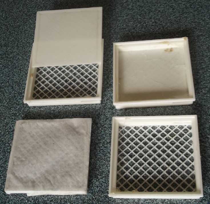
 I came up with
a new plan for stacking electrodes. They
would be identical box frames with socket and tenon (are those the
right words?) or "telescoping" fit together, a "lip" sliding over the
other side by about 2mm all the way around. They would be glued
together. A hole or slot half way across for the terminal tab. Instead
of a "basket weave" plastic grill outside the paper, the grill would be
inside and the parchment paper+PP cloth ironed onto the outside,
fitting into the next one. Thus only the one separator sheet would be
between 'trodes. These could be easily filled from their open face and
the materials packed in before gluing to the next one over.
I came up with
a new plan for stacking electrodes. They
would be identical box frames with socket and tenon (are those the
right words?) or "telescoping" fit together, a "lip" sliding over the
other side by about 2mm all the way around. They would be glued
together. A hole or slot half way across for the terminal tab. Instead
of a "basket weave" plastic grill outside the paper, the grill would be
inside and the parchment paper+PP cloth ironed onto the outside,
fitting into the next one. Thus only the one separator sheet would be
between 'trodes. These could be easily filled from their open face and
the materials packed in before gluing to the next one over.
Obviously this would be for
production with confidence the
electrodes will all work properly. It should be a good system for hand
assembly and not prone to leaks of powders. The amount of material
going into each 'trode will have to be carefully controlled, because
there's no sponge rubber spring at one end to push all them together if
the powders are loose. (unless the boxes aren't glued together and
they're slightly overstuffed -- but that would be prone to leaking
powders out of the boxes.)
 At some point
I tried ironing together the thin PP cloth
and parchment paper, and then ironing a piece of that onto the outside
of an electrode face grill. I cut a little alume block to fit inside to
iron against. It seemed to work. So far so good! With the separator
outside of the "basket" grill instead of inside, it didn't add a gap
between trodes, and the outside face of a single separator was the
inside face of the next.
At some point
I tried ironing together the thin PP cloth
and parchment paper, and then ironing a piece of that onto the outside
of an electrode face grill. I cut a little alume block to fit inside to
iron against. It seemed to work. So far so good! With the separator
outside of the "basket" grill instead of inside, it didn't add a gap
between trodes, and the outside face of a single separator was the
inside face of the next.
[The parchment paper proved too thin. It didn't hold
enough SDBS to prevent zinc dendrites, and watercolor paper is too
thick to iron through. So back to exact size watercolor paper
separators inside the trays.]
And I ordered some
acetaldehyde from Sigma-Alderich as I'm
about out - 165$ in preference to making it myself as I did in 2010 or
so. (It's sure nice having this "OAP" as an R & D budget!)
[10th] I ran into an unexpected hitch printing the stacking electrode
trays: I was virtually out of PVB 3D printer filament, so I tried ABS
filament. (PLA would probably disintegrate inside the cell.) While my
old RepRapPro 3D printer printed ABS quite nicely in smaller sizes, I
couldn't get the i3Mega to print it, nohow. The first time it went a
couple of layers, then a corner lifted, caught on the extruder, and the
whole print came loose. Every try after that was worse. I tried all
kinds of settings, I put cardboard over the printer with a 400 watt
radiant heater inside and got it up to about 45°. I tried Kapton
tape on the glass per one recommendation on line. Nothing worked. I
couldn't even get it to print the first layer before the whole thing
fell off the bed.
I looked for PVB filament and Filaments.ca was "out of
stock" on all PVB. I didn't like the look of importing - all pretty
costly. I must have a dozen spools of ABS already, and I would rather
use ABS anyway.
After all the frustration it finally occurred to me that I
had had the same trouble with PLA a year or two ago. My spools had been
stored out in the damp in the shipping container since I moved here. If
filament is the least bit damp it doesn't work worth a [choice of
expletive here]. This spool had been in a sealed plastic bag and now
had been inside for some time, but it had also been stored out there
for years. I set it near the woodstove and hope it will work properly
for these small parts in a few days or a week.
I decided to see how much I could still print with the
remaining strands of PVB. I did one tray, then tried putting it against
a "non tray" electrode box and realized that half of them should have
the terminal slot on the other side so the "+"es and "-"es weren't all
mixed together on one side. So I mirror image'd the design and printed
another one. The inside corners "round off" as the filament goes around
the corner, so to fit them together I cut a bit off the outside
corners. After that it was a great fit, first try! (If I'm doing a lot
I'll have the the outside corners rounded in the printing.)
Okay, two
trays for a line of 'n'. The line also needed a
starting tray with a solid 'bottom' instead of a grille and separator
sheet, and a solid cover over the 'top' tray. I thought the filament
might run out, but luckily there were still enough winds on the
spool... 17, 16, 15... 11, 10, 9. Yay!
That made three electrode trays with ends. Possibly enough
filament for one more. Great, except they seemed too precious to risk
using!
They're still 50x50x6mm trodes inside, but making them to
stack they occupy 57x57x6mm; 8mm for the top one. The PVB in each
(central) tray weighs 3.25 grams. That's a fair bit of overhead for
about 10 grams of zinc or copper hydroxide mix, but the separators are
ironed on and can be trimmed after, and the ingredients are open face
loaded into the trays, which are then immediately stacked together. It
should be much the easiest way to assemble electrodes & cells by
hand.
In the meantime I mixed 20
grams of fine zinc powder, 5
grams of conductive carbon black, and (around) .125 grams of zircon,
then added acetone to make a thin paste. Hopefully "co-depositing" to
mix the crystalline forms will work better than just mixing the
powders. As it was drying, I discovered it was getting lumpy so I
stirred it and broke up the bigger ones.
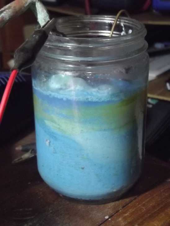 And I needed
more copper hydroxide for the next trodes, so
I mixed some more sodium nitrate and put in a couple of chunks of
copper in a jar. At about 4.6V it drew about 1.5 amps. For whatever
reason NaNO3 makes nice pure blue Cu(OH)2 where
other
salts make CuOH, CuOOH or mixed substances.
And I needed
more copper hydroxide for the next trodes, so
I mixed some more sodium nitrate and put in a couple of chunks of
copper in a jar. At about 4.6V it drew about 1.5 amps. For whatever
reason NaNO3 makes nice pure blue Cu(OH)2 where
other
salts make CuOH, CuOOH or mixed substances.
Potential?
[11th] I printed two more
trays to use up the last of my PVB filament.
(I was surprised to get one, much less two, out of nine winds of
filament on the spool.) The set weighed 19.0g. Each center one was
3.25g, so a "cube" of eight trays would be 28.75 grams. That would
contain about 40 of each powder for ideally maybe 25 amp-hours. Add 5g
x 8=40g for current collectors/terminals and 41.25g for a light outer
case and miscellaneous... 28.75 + 80 + 40 + 41.25 = 190 grams. At 1.1
volts, 27.5 watt-hours. 27.5 WH / .190 Kg = 144 WH/Kg. If actually
achieved in a homemade battery cell, that would be excellent.
Another possibility would be to 3D print water reservoirs
as upper sections of the trays and eliminate the outer case entirely.
This would shrink and lighten the cell considerably. And require that
the trays glue together perfectly - no leaks including no "porosity" in
the printed walls themselves. (160 grams, maybe? 27.5 WH / .160 Kg =
172 WH/Kg.) My confidence in this for prototyping isn't high enough to
try it.
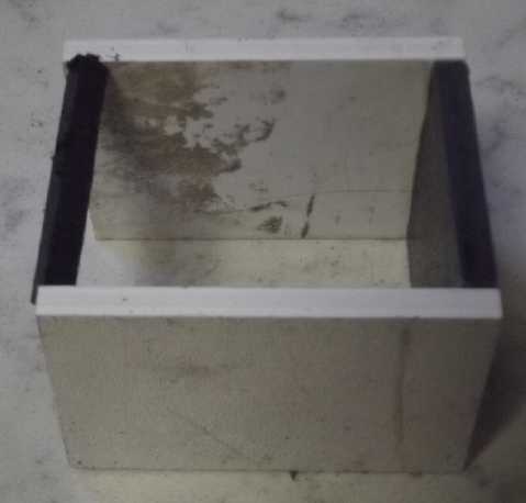 [12th] I made a new outer
case. With the extra couple of mm for the
overlapping edge lips, the old one was a bit too narrow. It was also
too
short to put a cover on when zinc trodes stuck up a bit. I made it long
enough to accommodate a string of 8 trays. (That was probably a mistake
since there'll be a lot of excess space to fill in for testing two
trodes at a time.) [Yes, I had to cut several filler pieces.]
[12th] I made a new outer
case. With the extra couple of mm for the
overlapping edge lips, the old one was a bit too narrow. It was also
too
short to put a cover on when zinc trodes stuck up a bit. I made it long
enough to accommodate a string of 8 trays. (That was probably a mistake
since there'll be a lot of excess space to fill in for testing two
trodes at a time.) [Yes, I had to cut several filler pieces.]
(Image: A little bar to keep the housing bottom, ends square while
gluing.)
Solving Zinc's Problems
In addition to describing the four basic problems with
rechargeable zinc electrodes, the paper linked last month (Electrically
Rechargeable
Zinc-Zir
Batteries:
progress,
Challenges and Perspectives)
describes things that have been tried to ameliorate them and get longer
cycle life. (As far as I'm concerned, if one gets less than a few
thousand cycles or a decade of use out of a battery, why bother?
Everyone will keep using lithiums... and if that was the case, maybe
I'd have been better off sticking with manganese as a negative?) The
best result they report on is someone mixing zinc and aluminum as
hydroxides, 75:25%, in alkaline solution. This gave 1000 cycles with
little deterioration. It didn't sound like the authors wanted to invest
in that. I suspect they thought mixing them would take a lot of
equipment and effort, because they didn't know about acetone, which I'm
(fairly)
confident would mix the substances properly.
From the book Alkaline Storage Batteries it sounds
to me like the most successful zinc battery cells were the old style
flooded alkaline cells with perforated metal pocket electrodes. What
did they have that newer designs don't? The metal "pocket electrode"
current collector was on the outside of the electrode.
Passivated oxide
couldn't build up on the outside surface because the outside is where
the electrode was connected. And there was a gap between electrodes.
Fine dendrites that tried to build up in the gaps were probably
"zapped" with current during recharge. The cells (it was said) would
work until simply too much zinc [as zincate ions] had migrated right
out of the electrodes, clogging up (or "poisoning") the positive
(nickel) electrodes with zinc [as oxide] while reducing the capacity of
the zinc side too much. Still they probably only got hundreds of
cycles, which isn't my definition of a real success for future
batteries.
According to the paper, one technique for "ameliorating"
zinc problems then is to put "heavy metals" at the outside surface.
There's no metal heavier than the osmium doping I've been using with
acetaldehyde, painting it onto the inside of the separator sheet.
Another thing was adding sulfonates to the separator
sheets. I've been soaking the whole electrode in sodium
dodecalbenzenesulfonate. But if zinc ions can't pass the separator
sheet, they can't deplete from the electrode nor form dendrites that
short out the cell. So probably saturating just the separator sheet is
sufficient,
and doing the whole thing may be one reason for poor currents. So next
I'll just do the separator. I'm not sure these two things - sulfate and
heavy metal - have been
combined before, and especially not these two specific ones.
Then of course there's adding something like graphite or
conductive carbon black ("CCB") to improve the internal conductivity of
the trode at all states of charge. Single digit percentages of carbon
black were mentioned. Also mentioned was the likelihood that
"co-precipitation" of the mixture would probably work better than
simply mixing them. This is what I believe I'm achieving when I
dissolve the powders in acetone to have them form epitaxial crystals as
the acetone evaporates, as I have done with the latest mix (10% CCB)
for the next zinc trode.
And of course everyone adds something to raise the
hydrogen overvoltage. I'm sticking with .5% zirconium silicate
(ZrSiO4), also "co-precipitated". It seems to work quite well if the
charge voltage isn't too high. (And hey, 3% of it plus 1% stibnite
(Sb2S3) even worked with
manganese, which "theoreticly" shouldn't even hold a charge!)
I skimmed the rest of the paper (about air electrodes) and
found some more useful info at the bottom, then decided I could stand
to read the entire section on zinc over again!
[13th] I soaked the ironed-on separator sheet in SDBS and then painted
the inside of it with osmium doped acetaldehyde. I folded up a copper
screen with a terminal of copper foil, then I painted that with calcium
oxide/hydroxide. Then I fitted it into the electrode tray.
[14th] I sprinkled in 5 grams of the zinc mix and put the solid cover
on the back. (I hope that's enough - it seemed a bit light. But it will
expand a bit as it discharges to ZnO.) I put on four adhesive strips of
foam rubber (weatherstripping) to press against the cell case
(with the right thickness of spacers) and hold the cover on. I didn't
glue the cover on
in case I want to add more electrodes to the stack later - or even to
check inside the electrode to see what the zinc mix is doing. (If it
leaks, the zinc goes outside the stack and can't get into the nickel
tray.)
I found the electrolysis a few days ago had produced 26g
of blue Cu(OH)2. I added 1.7g of graphite to this, about 6.5%, then
poured in some acetone and mixed to make a thin paste, to
"co-precipitate" epitaxial crystals. I set it by the woodstove to
evaporate out the acetone.
 [15th] I made a CuNi
current collector, painted it with calcium oxide,
and added about 5 grams of the Cu(OH)2 mix, now dried and crushed back
to powder. Before the mix it weighed 17 grams, so 22 grams. Much more
supporting structure than active powder - that's certainly no way to
get high specific energy! (I really need thin monel, not
heavy cupro-nickel "plate" for current collectors. If it has holes in
it to
eliminate some of the metal, so much the better! But it needs to be
more than "foil" or "window screen" because the outside oxidizes.)
[15th] I made a CuNi
current collector, painted it with calcium oxide,
and added about 5 grams of the Cu(OH)2 mix, now dried and crushed back
to powder. Before the mix it weighed 17 grams, so 22 grams. Much more
supporting structure than active powder - that's certainly no way to
get high specific energy! (I really need thin monel, not
heavy cupro-nickel "plate" for current collectors. If it has holes in
it to
eliminate some of the metal, so much the better! But it needs to be
more than "foil" or "window screen" because the outside oxidizes.)
I put the empty tray with a paper ironed onto the front on
top (to cover the open top of the nickel tray) and bleached it for 5
minutes in diluted bleach and then rinsed it for the same period. I
dried the outside of the tray off and glued the two trays together with
ABS cement.
I cut some ABS
spacers to fill in the extra cell length
since I had made the case to hold a stack of up to eight trodes. About
35cc of 10% KCl electrolyte filled above the tops of the trays.
 This time the cell was tall enough to put a cover on. Because of that I
didn't have to keep refilling it as the days went by.
This time the cell was tall enough to put a cover on. Because of that I
didn't have to keep refilling it as the days went by.
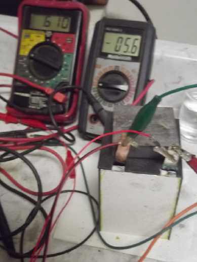
It started about like
usual. It said ~.9 volts and dropped
to .4 if I tried a 10 Ω load. With 1.35V charge it started charging at
17mA which soon rose to 19. After a while I tried some more brief load
tests, with slightly rising voltages as charging proceeded. After each
load, the charge would jump up from 19mA to 30, 40 or 50, depending how
much I had run it, gradually dropping back to the original low value.
There was no visible bubbling at least in the first hour. One type of
pH paper seemed to say pH was around 10-11 while another one claimed it
was about 6.5. (?? I'll try again later.) In an hour or so momentary
short circuit current was 350mA. Well, at least that's 1/3 of the amp I
hope for rather than 10-15%. Presumably it'll charge up. Then comes the
main question: does it degrade with each cycle or continue working?
[16th] It was degrading. I was at my wit's end. I thought of what very
different results I had got making copper hydroxide in KCl, MgSO4 and
NaNO3 salt electrolytes. Perhaps I should try something different. I
had already tried sodium nitrate. It hadn't seemed better... maybe a
different anion? I had a jar of K2SO4 from neutralizing the acid in
lead-acid batteries years ago. I mixed a 10% solution, dumped the KCl
liquid in the cell, and filled with this. It seemed to help. Then I
started thinking: what if the reaction voltage from Cu(OH)2 to CuOOH
was higher than I expected? What if the cell needed more than 1.4 volts
charging voltage? After all, in the earlier results that had got me
interested in copper, I had been seeing voltages around 1.3V.
So I turned the charge voltage up to 1.6V as I had been
using before. I meant to leave it for a couple of hours but was away
for about nine. In the evening it was charging at just 7 mA. I did a
load test and the results seemed incomparable. Off charge it held to
1.400V after one minute and the drop was very slow. While again it
started at under .8 volts with the 10 ohm load, the voltage started out
by rising for about 3 minutes (to .813V) instead of falling swiftly. I
wonder if the osmium helped convert passivated ZnO at the surface of
the trode into dissolved zincate, if not preventing passivation then at
least reversing it during discharge. I ran it for an 45 minutes at
which point the voltage had fallen under .6V. It recovered to a much
higher value (over 1.1V instead of ~.9V) and when I switched the charge
on it hit 212 mA, much the highest value yet, and was doing 70 mA after
a minute. (Momentary short circuit current had been down to about 235
mA at one point. It now passed 400.) After a little charging a quick 50
Ω test started out above 1.2 volts and 100 Ω was at 1.25 - up where
they had been in the best of the early tests using cupro-nickel sheet
as the copper and before the zinc started passivating.
[17th] It didn't seem to last. In the morning it held 1.435V open
circuit, but as soon as I put the 10 ohm load on it dropped to about
.7V, then rose over 5 minutes to just 7.23V - 90mV below the previous
evening. Well, what was the salt that had made the nice blue copper
hydroxide? Sodium nitrate. It seemed more "aggressive" than the other
salts. If sodium nitrate wasn't the thing, how about potassium nitrate?
How to make? The baking soda worked well for the sodium version, but
there's no potassium bicarbonate. I guess it'll be potassium hydroxide
& nitric acid. (Or what about that "instant cold pack" with
calcium-ammonium nitrate? I'd have to look the video up again.)
In a nickel-whatever alkaline cell, nitrate is an impurity
that causes self discharge via the "nitrate-nitrite shuttle". At the
negative, the nitrate is reduced to nitrite, discharging an electron.
At the nickel side, it is oxidized back to nitrate putting the electron
in to discharge that side. Obviously the zinc is way more negative than
needed to cause the reduction. My question is, at what voltage
does the nitrite oxidation happen? Obviously nickel oxyhydroxide is
high enough, but copper hydroxide or oxyhydroxide has a lower voltage.
Might the nitrate not turn back into nitrate? In that case we
would end up with a stable potassium nitrite electrolyte. On looking
that up, it is poisonous, a strong oxidizer and also incredibly
soluble: at room temperature, over 300 grams of it can be dissolved in
100 grams of water.
Current seemed awfully high, sitting around 35mA and not
dropping. Was it because of (a) nitrite doing a much better job of
charging the cell's electrodes?, (b) charging of the nitrate into
nitrite?, or (c) the nitrate-nitrite shuttle, wherein the charge
current would match the self discharge and never reduce? A few hours
would probably tell. Well, altho the charge current gradually dropped
over the day, it wouldn't run a load properly. It held charge more like
a leaky capacitor than a battery. Sigh!
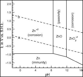
Zincate?
Okay... if we're going out on limbs... how about soluble
"zincate" anion? This is variously described as or composed of:
ZnO2-- (Forms only at highly alkaline pH'es?)
Zn(OH)4-- (shown in some diagrams in place of ZnO2--. It's about the
same thing + 2 H2O)
Zn(OH)3- (shown in some diagrams. might be more likely to form in
a more neutral
solution)
HZnO2- (Shown on right diagram - in place of above?)
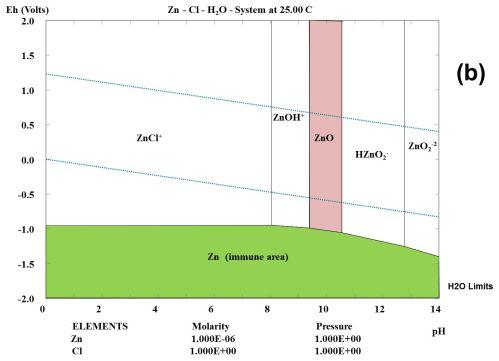
One Pourbaix diagram shows these different
electrochemical results for zinc in chloride at different pH'es and
voltages. And then there's at different concentrations, the right
diagram having only a little zinc.
I can't find much of anything about the solubility or
properties of these various substances on Wikipedia. I have heard that
"the solubility of zinc is lowest around pH 9". That means that
contrary to the diagrams it is at least somewhat soluble at any
pH. At how low a pH can there be some form of zincate anion? It looks
like 12 or higher should do it. What would
form in a neutral salt environment? Suppose we assumed that given a bit
of free potassium a very limited amount of dissolved KZn(OH)3 - or
K2Zn(OH)4 would form? The "free" potassium would be its hydroxide, ie:
KOH + Zn(OH)2 => KZn(OH)3 or 2 KOH + Zn(OH)2 => K2Zn(OH)4. Would
such salts or hydroxides be neutral or basic? How much would be
dissolved if the main salt was KCl (or K2SO4)?
My thought is that some form of zincate is the one form
that might dissolve passivated ZnO off the surface of the zinc trode,
and thus essentially prevent it from happening. At least, it's an idea
that might have that potential. I decided to go back to potassium
chloride add just a bit of potassium hydroxide. Would it convert to
some sort of potassium zincate and stay near neutral pH, or would it
just remain KOH and make it alkaline - without improving the
performance? Or maybe I should let it become somewhat alkaline in order
to form zincates, and that might improve the performance?
[18th] A little flake of KOH (.15g) raised the pH to 11-11.5 or so and
it just stayed up there. The cell didn't seem to work any better. If I
can't figure out some way to prevent the zinc from passivating then the
whole idea of using zinc, with all the things I've done to prevent
dendrites and other problems, will have been for naught. I'm sure there
must be a way, and probably more than one way - can I find one?
Hmm... According to some Pourbaix diagrams pH has to be
over 12 to make zincate. So I added another flake. pH 12? Later I added
another. (I found no figures on the solubility of zincates, but I
suppose if I had raised the pH to over 12 with calcium like I usually
have done, CaZnO2 instead of K2ZnO2
might well be essentially insoluble and if so probably wouldn't help
eliminate passivation.)
It didn't seem to help, just to raise the pH. Well, was
zincate really forming? What about some actual zincate? I had some
sodium zincate solution in a bottle. I added a couple of drops. Nothing
seemed to change. But I thought zincate should form by itself and
didn't continue.
[19th] I added some more KOH, eventually to about 1.65 grams - around
5-6%. pH went up to around 13. It seemed to be having an effect. Load
voltages with 10 ohms were still only around .6 volts and gradually
dropping from there, but they weren't getting worse with each
passing
cycle. That was a significant result.
[20th] I took the (yay, not
glued!) back off the zinc tray. The zinc had
settled into the lower part of the box, maybe 60% full. Certainly no
compression/compaction in there. I added another 3 grams of the zinc
mix. It didn't do much when I first put it back in, but after just a
minute of charging - at higher currents than before - I tried the 10
ohm load. The voltage hardly dropped. Off again it hardly rose. On
again, very slight drop. I thought I had a bad connection or something.
Then I looked at the current. Sure enough, instead of the voltage
dropping way down, it was supplying over 110mA starting at about 1.25
volts -- 5+ mA per square centimeter of interface area with hardly any
voltage drop -- just like it should have always worked but never has!
It didn't last. With the short charge (@ 1.6V), load
voltage soon started dropping back to .6V levels. And it didn't come
back up. And charging currents got ridiculously low for something that
needed charging. And yet, when charge was stopped the open circuit
voltage only gradually fell from 1.6 volts, suggesting that it didn't
actually need charging. And why should it? - it had charged all night
and the new material was zinc metal, not oxide.
It still didn't seem like a lot of zinc. I added another
2.6 grams; total now 10.6 grams. That might actually be filling the
tray and have a bit of pressure from the foam rubber behind it. I got a
similar result to the previous adding - great for a few seconds.
Putting another piece of plastic filler in to press the foam rubber
against the back of the tray harder didn't seem to do much. But the
load voltages were up toward .7 volts - a little less. A little more
charging and they passed .7.
What could need charging?
Perhaps new conductive pathways
have to form between the carbon black particles and the zinc dust? How
could it work great for a few seconds but only once? I certainly don't
have the answers! What can charging at unit milliamps do?
But I do have one answer: The fact of great performance
(even
just once for a moment) after working only on the zinc trode suggests
that the copper hydroxide side works great already. Only the zinc side
has troubles, and if it works right twice, why can't it work right
always?
[21st] pH still about 13. Steady-state charging is now at 12mA, up from
9. (@ 1.6V. No bubbles.) Doesn't seem to work any better. Will keep
charging. By evening 13mA. And it drops pretty quickly to 1.140V when
taken off charge. These don't seem like good signs - incrementally
worse? A 10 Ω load started at .65V and worked its way up over .7 over a
few minutes. (Ran it about 15 minutes.) Momentary short curcuit current
is over .5 amps. After that charging current was over 200mA when first
started. Those things seem incrementally better. As noted some recent
time back, it seems to charge painfully slowly, but after running a
load it returns to its previous state of charge quickly before dropping
off to almost nothing again. At such low long-term charging currents,
if it ever gets to good performance it's because it's not deteriorating
over an extended period. Let's give it another day? or ten? I lowered
the charge voltage to 1.5. It doesn't hold above 1.3 and 1.6
seems a little high, even tho there's no bubbling evident.
[22nd] Still at 13mA in morning. Open circuit drifted down to over
1.17V instead of 1.14V. I don't know what, if anything, could actually
be "charging". With a 10 Ω load the voltage still starts a little over
.6V and creeps up over several minutes to almost .7V - 2/3 of what it
should be, if. In fact, it was still rising for over 12 minutes, twice
as long as ever before, hitting .694V before starting to drop. After
this short circuit current was still well over 400mA. Maybe something is
still "initially charging" at this low, low rate? Copper hydroxide to
oxyhydroxide? Ten days may not be an underestimate to get a fairly full
charge.
There's somethin' happening here....
What it is ain't exactly clear....
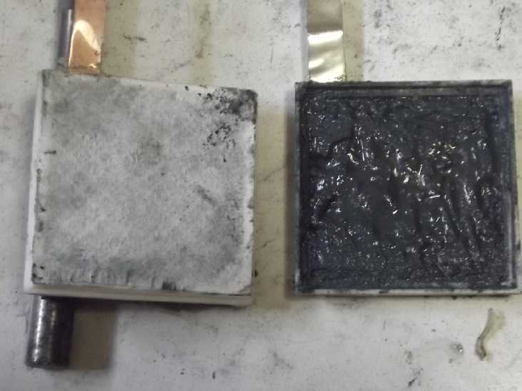
It's too bad the copper tray is glued shut. It would be
nice to see the color of the compound within:
Nickel hydroxide: Turquoise; Copper hydroxide: Sky blue (dark blue-gray
mix with graphite powder)
Nickel oxyhydroxide: Black ; Copper oxyhydroxide: Black ?
By evening the steady charge current was up to 14mA. It
still drops to lower .6 volts when the 10 ohm load is started (rose to
.686 in 3 minutes). However, at least it isn't notably deteriorating -
it's not dropping to .5XX, .4XX and .3XX on successive days. Short
circuit current current remains high as do charging currents after a
load. I think making it alkaline enough to form zincate ions, perhaps
pH 13(?), has been key to preventing zinc oxide passivation. I used:
10% KCl
5-6% KOH
That's more alkaline and more KOH than I like, but if it
works and a lower pH doesn't, I'll run with it. It's not as caustic as
more concentrated KOH solution. I can run experiments later to see if
it's more than what's needed.
[23rd] Steady charge was up to 18mA. When I took it off the voltage,
instead of drifting lazily down, dropped to 1.061V in a matter of
seconds, then went up a bit to 1.065 - as if it was driving a light
load. I suspect a zinc dendrite may be causing a low resistance path
between electrodes. A dendrite(s) through the supposedly protected
separator sheet would be most unwelcome - I thought I had that solved.
It may be on the outside of the trays, as I noted black zinc dust
coating the outsides of the white PVB a couple of days ago. (That's the
down side of not gluing the back on the end tray.) Or the sheet isn't
well enough ironed onto the tray and there's a gap at an edge.
Loads ran about the same as previously - meaning voltage
drops way too much, and then starts rising again but is still way lower
than one expects. Why doesn't it drive even 5mA/sq.cm at a little under
its open circuit voltage? Short circuit current seemed to be down, to
about 400mA. Charging currents after a load remained much higher than
previously starting at over 1/4 amp and staying higher longer.
[24th] In fact, any "exercising" of the cell, running and charging for
short periods, increases every aspect of the performance. Especially at
higher currents, which now means low hundreds of miliamps rather than
mid-upper tens. Charging for hours at the low rate (now up to 18mA)
makes if worse, even as it gradually runs longer and longer.
I suspected the glued sides between the two trays were
leaking and powder was bridging the electrodes. I took it out and
brushed the sides off, removing quite a bit of powder especially around
the terminals. It was soon holding higher open circuit voltages again.
(Not dendrite(s) across the separator - yay!) Presumably the "steady
state" charging current would drop. (Yes - down to 15mA in an hour or
so, another hour, 12.)
[25th] By morning charging was up to 19mA again. I took the electrodes
out, brushed the fresh coating of black powder off the top, and noted
that the whole top seam had water going in and out as I touched it. I
left it out to dry off, then smeared heat glue around the outside seam
on all four sides. I hooked it back up and it was very soon down to
10mA, and when disconnected, drifting down from the 1.5V charge as by
parachute instead of like a rock.
[27th] Current rose gain to 17mA. I took it apart and brushed it off
again. It still seemed to be leaking powder somewhere. (It might be
from not gluing the back on.) Not wanting to glue the back, there
wasn't much more I could do there except make another pair of trodes.
Instead I poured out the dirty electrolyte and decided to get more
adventurous again. I made new electrolyte with 10% KCl, 10% K2SO4 and
7.5% KOH. My K2SO4, made long ago from a lead acid battery by adding
KOH to the H2SO4 to neutralize it, seemed to have a lot of crud in it.
I dumped it out and tried again, replacing that with Na2SO4 (USP
purity). The Na2SO4 didn't all dissolve and I finally gave up waiting
while there was still a swirl of it on the bottom. It's only around 15%
soluble to start with (@ 15°C), and had an especially large, hard
lump in it. (In fact, below 10° it is under 10% soluble. I don't
think it was that cold where I was working. Potassium sulfate
is similar. Magnesium sulfate is more soluble.) More: Maybe the figure
in Wikipedia solubility table is for the decahydrate? (although it
didn't say so), where I had anhydrous?
The voltage started out at .6xV and gradually rose by
itself to .95V. A 10 ohm load quickly dropped it to .5V. It started
charging at under 200mA. Trying it out, voltage with the load seemed
down some. I ran it for 1/2 hour to .45V. After that voltages seemed to
be up somewhat - sort of typical actually. Another load test looked
almost identical to some previous ones. pH seemed to be up to 14, and
it charged without visible bubbling. I've seen some bubbling on a long
discharge. With little bubbling and a lid placed on top, I don't have
to keep filling this cell. (I had to fill the last one, with things
sticking out the top and no lid, about every day.)
[29th] Continuing charging and testing the same cell, after two weeks
it's performance now seems to be improving. Any time I interrupt a load
test and short it out for a few seconds, the discharge voltage rises
by tens of millivolts over the next 20 seconds or so before resuming
its slow drop. And the higher currents are rising. Momentary short
circuits sometimes put out over 900mA instead of 500. After a load test
charging may start at over 400mA instead of 300, and it stays higher
longer.
That's not to say that discharge voltages are up where
they ought to be. Instead of putting out over a volt a with 10 ohm
load, it drifts down toward .65 or .6V over 10 minutes or so - unless
it's occasionally shorted out. It'll run for hours above .4V, but why
not above 1.0V? It feels like the voltages go up and down with the
percentage of the surface that's passivated, since the state of charge
with a 10 ohm load should only change very gradually. I'm guessing
there's probably only 5 to 20% open most of the time, where the
objective (assuming it can't be entirely avoided) would be to have at
least much of it open most of the time.
I think I will make another "stack" of two trays -
assuming the 3D printer/ABS filament will print them. This time I'll
use the new acetaldehyde I've just bought (instead of my old homemade
stuff - 2011?) with another little dram of 'fresh' osmium powder,
because I suspect that's what is underperforming and allowing buildup
of passivated ZnO, and that that is what is causing the low voltages.
But it is heartening that the cell doesn't continue to deteriorate
further and further. At least some of the passivation must repeatedly
get dealt with as it runs and it doesn't gradually die like previous
cells.
[31st] The cell continues to work as well as it was if not better. [But
the "idle" charge current continued to rise - zinc dendrites?]
For new electrodes I re-"sliced" the end pieces with ABS
settings, put the ABS spool in the 3D printer and turned it on. I used
Kaptan tape on the bed (said to hold ABS better) at 105°C, and put
cardboard over the printer with a 400W heater inside to keep the print
warmer and reduce ABS's tendency to warp. With the ABS now "dry" from
sitting by the woodstove for weeks, it printed. This is a relief as I
have a number of spools of it and PVB is not only costly: I can't find
it on line. "Out of stock". BTW I see why I couldn't get PVB to soften
or melt with alcohol: it has to be isopropyl alcohol. No doubt I read
that and then just remembered "alcohol" when I tried it.
Anyway enough of PVB! -- The ABS prints came out much
cleaner. OTOH, the bottom corners of the bottom tray shrank up a bit,
and the bottoms seemed yellow from the Kapton tape. But, good enough!
Owing no doubt to the cleaner printing, the trays were a sloppy fit
together. I'll have to use heat glue instead of ABS cement.
[April 1st] I couldn't get a good print of the inner trays with the
traces lifting and making a mess, and finally gave up in frustration.
Why could the old RepRapPro print ABS pretty nicely in open air, but
the iMega can't even in a cardboard box with a 400 watt heater inside
to keep the whole thing warmer?
Suddenly it hit me: The old "Pronterface" slicer did .4mm
thick vertical layers. I was now doing .2mm height with "Cura". Thicker
traces would be stiffer and harder to lift off the bed as more layers
printed on top and shrank as they cooled. Cura calls .2mm "good" and
.3mm "draft mode". But it can be told .4mm, and I will certainly try
it! Also the old printer, with .4mm, printed things a heck of a lot
faster. (I'll have to adjust the designs to account for .4mm layer
heights.)
[April 2nd] In the paper on zinc-air cell research from 2017, some of
the things I've done were hinted at as possibilities or things being
tried. Sulfonates and calcium oxide were mentioned as well as using "a
heavy metal" at the surface of the zinc. (There's nothing heavier than
osmium!) Owing to these similities of approaches I spent time during 3
days composing a letter, the head author's email being listed in it at
University of Waterloo in Ontario. I summarized my own research and
experiments and on the 2nd added some photos, then sent it.
The leakage current of the present cell grows worse. I
think the parchment paper is too thin to hold enough SDBS to stop all
the dendrites. I'll go back to watercolor paper. I had thought it was
causing low currents and hence wanted to try thinner separators, but
now I expect it was the zinc oxide surface passivation causing most of
the low current problems.
[April 3rd] I had been noting that the "steady state" current continued
to rise, from the original 7-9 mA it was now up over 40. even after I
took it apart and brushed off the trays. So it would seem then that
conductive paths, zinc dendrites, must be forming across the separator.
No doubt the parchment paper is too thin for the SDBS in it to stop the
zinc ions.
It finally occurred to me overnight that because I hadn't
glued the back on the zinc tray I could open it, scoop out the
contents, put a new treated separator paper on the inside of the grill,
and then reassemble it. I didn't need to make a whole new cell to put
in a thicker watercolor paper complete with SDBS and the new
acetaldehyde. Hopefully that would not only stop the dendrites but make
the whole cell work better. (Maybe I should punch/rip some big holes
through the original separator before I put the new one in?
[April 4th] I took apart
the zinc tray. I scooped out what zinc mix I
could. It was pretty loose and of course a paste rather than
powder. Because the paper was on the outside of the basket weave
'grill' it was stuck between all the "X"es. I had to take a brush and
brush
the rest out under running water.
I got out and trimmed to 50x50mm size a toluened piece of
watercolor paper. When I opened the new acetaldehyde, I realized that I
hadn't smelled that flowery fragrance in years. Doubtless my old stuff
was long since degraded away. I dripped some in a test tube with an
eyedropper and tapped in a bit of osmium powder from the tiny bottle.
(There's more left of my 1 gram of it than I had thought.) I stirred it
with a tiny brush and painted it onto - more like into - the paper. It
took the whole amount, about 1cc. The liquid was clear but with the
powder it painted on a dark color. (If I had tried to make it uniformly
dark I'd have used a lot more, so I didn't. Don't hire me as a
painter.) Then, without waiting for it to dry, I immersed it in SDBS
for an hour.
[April 5th] The new separator seems to
have stopped the dendrites.
Charge current dropped overnight to 2mA. But the cell performs no
better than before. I think I need to rethink what the "surface" of the
electrode is.
In a "standard" dry cell, the zinc is a sheet around the
outside of the cylinder. This gradually dissolves as zinc chloride with
discharge. (until finally it leaks out.) In an alkaline cell, the zinc
is a gritty powder. the large surface area of all this allows higher
currents.
But with a sheet of zinc, the surface of the electrode is
the surface is the surface of the sheet. This is indeed right next to
the separator and so painting the separator with osmium is effective.
With powder the surface of the electrode is the surface of all the tiny
particles that touch the electrolyte. So in theory I should be doping
the whole substance of the powder with the osmium. It seems to me that
would take a prohibitive amount of osmium, the rarest of all naturally
occurring elements.
So what if I go back to using sheets of zinc, or zinc
plated onto copper? Painting the doped acetaldehyde onto a smooth zinc
surface will take less of it than painting it anywhere else and be
right to the point. The SDBS soaked separator will still stop
dendrites. One could even put in several doped "leafs" of smaller zinc
sheets (or thinner "zinc foil"?) if one sheet didn't make for high
enough current or storage capacity. Why didn't I think of trying this a
couple of months ago? Oh ya, I was just learning about zinc passivation.
Anyway, metal sheet electrodes would be simpler for
"homemade". Okay, here's the zinc coated copper sheets that Peter sent
me from Oregon about 4 years ago. I'm sure I've been more on "right
tracks" before but something didn't go right and I switched direction.
To Be Continued...
I'll stop here and continue in the April newsletter, but
it's the most promising experiment I've thought of in a while.
Electricity
Generation
My Solar Power System
The Usual Daily/Monthly/Yearly Log of Solar
Power Generated [and grid power consumed]
(All times are in PST: clock 48 minutes ahead of local sun
time, not
PDT which
is an hour and 48 minutes ahead. (DC) battery system power output
readings are reset to zero
daily (often just for LED lights, occasionally used with other loads:
Chevy Sprint electric car, inverters in power outages or other 36V
loads), while the
grid tied readings are cumulative.)
Daily Figures
Notes: House Main
meter (6 digits) accumulates. DC meter now
accumulates until [before] it loses precision (9.999 WH => 0010
KWH), then is
reset. House East and Cabin meters (4
digits) are reset to 0 when they get near 99.99 (which goes to "100.0")
- owing to loss of second decimal precision.
Km = Nissan Leaf electric car drove distance, then car was charged.
New Order of Daily Solar Readings (Beginning May 2022):
Date House, House, House, Cabin => Total KWH Solar [Notable
power
Uses (EV); Grid power meter@time] Sky/weather
Main
DC East
(carport)
After 5 full years, I am no longer recording solar
collection figures daily. (Frequently, and surely monthly.)
February
29th 1014.55, .82, 21.16, 5.52=>12.99 [13659@18:30]
March
01st 1016.13, .88, 21.68, 6.14 =>
2.78
[13683@19:00] 1day
05th 1031.33, 1.14, 30.96, 16.41 => 35.01 [13779@18:30] 4d
10th 1047.89, 1.36, 39.24, 25.91 => 34.56 [13922@18:00] 5d
12th 1054.29, 1.50, 42.48, 29.60 => 13.47 [13972@23:30] 2d
13th 1056.94, 1.57, 43.96, 29.93 => 4.53 [13994@19:00] 1d
14th 1059.61, 1.66, 45.41, 31.74 => 6.02 [14024@19:00] 1d
16th 1071.78, 1.82, 51.87, 38.95 => 25.90 [14090@19:30] 2d Yay for
sunshine!
18th 1076.76, 1.86, 54.25, 41.97 => 10.42 [14121@19:30] 2d
21st 1098.95, 1.96, 66.04, 56.48 => 46.59 [14177@20:00] 3d
22d 1107.58, 2.01, 70.66, 62.20 => 19.02 [14201@19:30] 1d
24th 1124.01, 2.10, 79.33, 73.04 => 35.95 [14246@22:30] 2d
25th 1128.25, 2.15, 81.65, 75.76 => 9.33 [14258@19:30] 1d
quiet AM then RAIN!
26th 1135.54, 2.18, 85.41, 79.98 => 15.30 [14272@19:30] 1d sun,
clouds, sun...
27th 1137.31, 2.23, 86.17, 81.03 => 3.63 [14308@20:00] 1d
rain, clouds.
28th 1146.33, 2.30, 90.09, 86.33 => 18.31 [14320@19:30] 1d sunny
29th 1155.59, 2.35, 93.99, 92.14 => 19.02 [14333@20:00] 1d mostly
sunny
31st 1164.64, 2.45, 5.12, 5.88 => 20.15
[14376@19:00] 1d
April
1st 1168.64, 2.49, 7.23, 8.40 =>
[14396@19:30] 1 day
3rd 1185.20, 2.57, 15.50, 18.44 => [14438@19:30] 2d
5th 1196.63, 2.68, 22.06, 25.69 => [14484@19:30] 3d
6th 1203.34, 2.76, 25.41, 29.74 => 14.19 [14511@21:30] 1d
7th 1208.12, 2.82, 28.19, 32.65 => [14538@20:00] 1d
9th 1223.63, 2.95, 36.47, 41.88 => [14598@20:00] 2d
Chart of total KWH from solar panels.
(Compare March 2024
(left) with February 2024 & with March 2023.)
Days of
__ KWH
|
March
2024
(18 Collectors)
|
February 2024
(18 C's)
|
March 2023
(15 then 17
collectors after
wind damage.)
|
0.xx
|
|
1
|
|
1.xx
|
|
2
|
3
|
2.xx
|
1
|
4
|
1
|
3.xx
|
1
|
|
|
4.xx
|
1
|
2
|
2
|
5.xx
|
2
|
2
|
2
|
6.xx
|
8
|
4
|
4
|
7.xx
|
|
3
|
|
8.xx
|
4
|
2
|
2
|
9.xx
|
1
|
2
|
4
|
10.xx
|
|
2
|
1
|
11.xx
|
|
3
|
4
|
12.xx
|
2
|
1
|
1
|
13.xx
|
|
|
2
|
14.xx
|
|
1
|
1
|
15.xx
|
3
|
|
|
16.xx
|
|
|
1
|
17.xx
|
|
|
|
18.xx
|
1
|
|
|
19.xx
|
2
|
|
|
20.xx
|
1
|
|
|
Total KWH
for month
|
337.81
|
201.53
|
298.14
|
Km Driven
on Electricity
|
1049.1
(~~140 KWH)
(ODO 106641)
|
967.2
(130 KWH?)
|
954.9
(140 KWH?)
|
Things Noted - March 2024
* Quite sunny: First time over 300 KWH of solar power in March. (March
2023 was 298 KWH)
Monthly Summaries: Solar Generated KWH [& Power used
from
grid KWH]
As these tables are getting long, I'm not repeating the log of monthly
reports. The reports for the first FIVE full years (March 2019 to
February 2024) may be found in TE
News
#189,
February
2023.
2024
Jan KWH: 31.37 + 3.14 + 16.85 + 16.82
= 68.18 [grid: 909; car (very rough estimates): 160]
Feb KWH: 96.52 + 2.36 + 49.67 + 52.98 = 201.53
[grid: 791; car: 130]
FIVE full Years of solar!
Mar KWH 150.09+ 1.63 + 93.59 + 92.50 = 337.81 [grid: 717; car:
140]
Annual Totals
1. March 2019-Feb. 2020: 2196.15 KWH Solar [used 7927 KWH
from grid; EV use: -] 10, 11, 12 solar panels
2. March 2020-Feb. 2021: 2069.82 KWH Solar [used 11294 KWH from grid;
EV use: -
(More electric heat - BR, Trailer & Perry's RV)] 12 solar panels
3. March 2021-Feb. 2022: 2063.05 KWH Solar [used 10977 KWH from grid;
EV use ~~1485 KWH] 12 solar panels, 14 near end of year.
4a. March 2022-August 2022: in (the best) 6 months, about 2725 KWH
solar - more than in any previous entire year!
4. March2022-Feb. 2023: 3793.37 KWH Solar [used 12038 KWH from grid; EV
use: ~1583 KWH] 14, 15, 18 solar panels
5. March 2023-Feb. 2024: 3891.35 KWH Solar [used 7914 KWH from power
grid; EV use: ~1515 KWH] 18 solar panels
Money Saved or Earned - @ 12¢ [All BC residential elec.
rate] ; @
50¢ [2018 cost of diesel fuel to BC Hydro] ; @ 1$ per KWH [actual
total
cost to BC Hydro
in 2022 according to an employee]:
1. 263.42$ ; 1097.58$ ; 2196.15$
2. 248.38$ ; 1034.91$ ; 2069.82$
3. 247.57$ ; 1031.53$ ; 2063.05$
4. 455.20$ ; 1896.69$ ; 3793.37$
It can be seen that the benefit to the society as a whole
on Haida Gwaii from solar power installations is much greater than the
cost savings to the individual user of electricity, thanks to the heavy
subsidization of our power
owing to the BC government policy of having the same power rate across
the entire province regardless of the cost of production. And it can be
insurance: With some
extra equipment and a battery, sufficient solar can deliver essential
power in
electrical outages however long. (Feb 28th 2023: And it's probably well
over 1$/KWH by now the way inflation of diesel fuel and other costs is
running.)