Turquoise Energy News Report #189
Covering
Research & Development Activities of February 2024
(Posted March 9th 2024)
Lawnhill BC Canada - by Craig Carmichael
[CraigXC at Post dot com]
www.TurquoiseEnergy.com
= www.ElectricCaik.com
= www.ElectricHubcap.com
Month In "Brief"
(Project Summaries etc.)
-
Five Years of Solar Power - "Everlasting" Cu-Zn
Battery Development - Terminology: Anode, Cathode &
Electrodes - Open Loop Air Heat Pumping: Making the heat exchanger -
Better Peltier Coolers Project - Cabin Construction
In
Passing
(Miscellaneous topics, editorial comments & opinionated rants)
- Scattered
Thots (Viewpoints, Citizen Participation in Governance) - ESD
- Detailed
Project Reports
-
Electric
Transport - Electric Hubcap Motor Systems
(no reports)
Other "Green"
& Electric Equipment Projects
* Making indoor-outdoor heat exchanger for Open Loop Heat Pumping
("OLAHP")
* Cabin Construction
Electricity Storage:
Batteries
* Much work and several experiments - 'everlasting' Copper-Zinc cell
looks closer
Electricity Generation
* My Solar Power System: - The Usual Latest Daily/Monthly
Solar Production log et cetera - Monthly/Annual Summaries,
Estimates, Notes
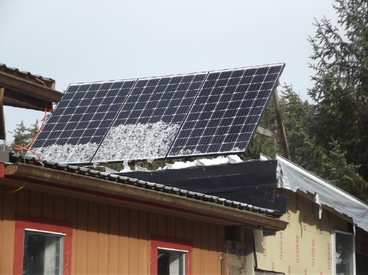
February in Brief
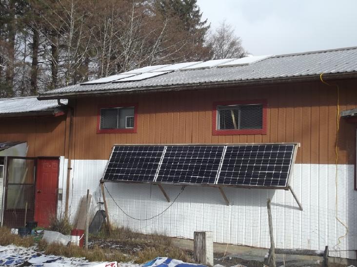 On the morning of the 28th it had
snowed overnight (or was it hail?),
On the morning of the 28th it had
snowed overnight (or was it hail?),
covering solar panels - but the more vertical ones under the
eaves were producing.
(It stayed cold and hailed again in early March.)
 The steeper ones on the carport
were shedding it,
The steeper ones on the carport
were shedding it,
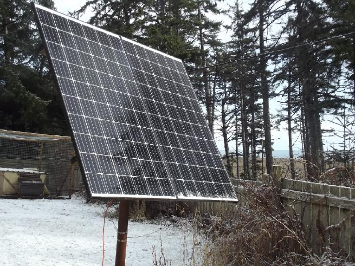 as were the steep ones on a pole.
 But the shallower angled ones on
the roofs stayed covered until mid afternoon.
But the shallower angled ones on
the roofs stayed covered until mid afternoon.
If it wasn't for the snow, the black panels would have heated up and
melted the snow!
Notwithstanding the last days, this was the sunniest February with the
highest solar collection yet.
Five Years of Solar Power
Readings from five full years of solar power from March
2019 to February 2024 are summarized under Electricity
Generation below. The last year has been the most
successful yet, with 3891.35 kilowatt-hours of solar electricity
generated. That is about half my entire electrical usage over that same
year (partly because living alone now I seem to have used less than in
other years). 'Theoreticly' then 36 solar panels instead of 18 and
battery storage could have supplied all needs, but it doesn't work out
this far north because the highest use is in winter when there is
little production. I am sending excess power to the power grid in the
four summer months, making more than the electric car uses in the
spring and autumn months, and using much more than is made in the three
darkest winter months of November, December and January when there
isn't even enough for the car, let alone electric heat.
The overall annual power bill would be much reduced,
mostly in winter for heating, if I had the open loop air heat pumping
system working as planned and installed in all heated spaces. (I did a
write-up on the theory of operation for that last month. [TENews #188 - search for
"Recap" in Month in Brief]. With the
efficient air compressor-decompressor design, I'm working on the
project again.)
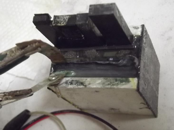
"Everlasting" (Cu-Zn) Battery Development
 Over the last four months now I've concentrated heavily on the battery
project, and with freezing weather toward the end of February and well
into March, I kept working indoors on it. And I finally found out what
a problem I've been having for years has been. Right at month's
end and the start of March I thought I had a working battery that
didn't seem to degrade with cycling. Each cycle seemed
roughly comparable in running time. But in fact the initial voltage was
dropping gradually - just
much more slowly than before.
Over the last four months now I've concentrated heavily on the battery
project, and with freezing weather toward the end of February and well
into March, I kept working indoors on it. And I finally found out what
a problem I've been having for years has been. Right at month's
end and the start of March I thought I had a working battery that
didn't seem to degrade with cycling. Each cycle seemed
roughly comparable in running time. But in fact the initial voltage was
dropping gradually - just
much more slowly than before.
The problem that I had been oblivious to all along I
finally discovered in a
paper
specificly covering zinc electrodes: zinc can passivate. More or
less non-conducting zinc oxide solidifies from dissolved zinc ions
during recharge and covers the surface of the electrode substance more
and more densely until it blocks electrolyte flow. That's surely
what's been happening to my cells, so much frustrating me for years
because I didn't know what was happening. I had thought zinc was
supposed to be
"perfect" in this regard and so I continually misattributed the cause
to the positive electrodes (even of different chemistries - including
copper at the start of the month!) and of
course nothing I did to them helped.
There's yet another problem with zinc? I started thinking
I had been doing better with metallic manganese negative electrodes in
2013!
I added quite a lot of graphite powder to the zinc (19
wt%, ~40% by volume) to give it conductivity regardless of its state of
charge, zinc metal or oxide, and the cycle after cycle deterioration
was much less. But not zero.
However, knowing what the problem is makes it possible to
start looking in the right place for the solution.
My cells also still have the problem of very low current
capacity - unit milliamps per square centimeter instead of tens. Zinc
usually has high current capacity. The doped osmium sheet and the SDBS
gel seem to slow current flow down quite a lot, but without those the
cells would
have short cycle life. (...regardless of passivation) The positive
electrode boxes are useful for
making the cells, but the copper oxide being spaced away from the zinc
and behind a second separator sheet surely doesn't help either.
So I started thinking about other ways to put everything
together... ways that are still doable by hand... and in early March
came up with a plan for electrode "trays" that stack together with just
one common separator sheet between trays.
And perhaps a solution to the passivation problem will
entail a remedy to the low capacities at the same time.
Terminology: Anode & Cathode, Negative & Positive Electrode
I took the trouble the actually think about this. (Long
overdue) I've had the concepts of "cathode" and "anode"
reversed in my head. In vacuum tubes the cathode, the negative side,
emits electrons toward the anode, the positive side, which absorbs
them. It only emits electrons. It doesn't absorb them from the
circuit as such, and so I always thought of cathodes as electron
sources. But
that's inside the tube. Inside a semiconductor diode the
cathode also emits electrons toward the anode, the positive side.
However it receives these electrons from the external wire that powers
it, and the anode transmits the electrons that it got from the cathode
to its external connection. In both cases the cathode is the negative
side and the anode the plus. Viewed from the outside the
cathode absorbs electrons and the anode emits them.
In battery usage then the anode also emits the electrons
it got
from
the electrolyte to its external wire but as the negative electrode
instead of the positive since the battery is sourcing power rather
than using it. The cathode pulls electrons from the external circuit
into
the electrolyte as the positive.
But I think the reason people use these otherwise
rather obscure terms instead of the more obvious "positive
electrode" and "negative electrode" has to do with length: "anode" and
"cathode" are each two syllables instead of six. (As in "Metric
System Length Problem: the real reason English Imperial measures are
better", eg, "inch" is one syllable "centimeter" is four. [TE News #125 for more
examples - scroll down from link])
Open Loop Air Heat Pumping (OLAHP)
 When it wasn't too cold out I managed to get a bit of work done on the
indoor-outdoor heat exchanger component. I put together the 24 x 60 x
7.5
inch box, cut some
insulation and got together fittings to join the pipes together.
When it wasn't too cold out I managed to get a bit of work done on the
indoor-outdoor heat exchanger component. I put together the 24 x 60 x
7.5
inch box, cut some
insulation and got together fittings to join the pipes together.
There isn't going to be much insulation above and below
the zig-zag rows of pipes. I discounted in my mind how much room
insulation takes up until I actually tried fitting things. The big
faces, front and back, do get 2 inches each - leaving only 3.5 inches
for the finned pipes, which are up to 2.5 inches square - just 1/2 inch
front and back, much less top and bottom.
I suppose when it's warm enough to work on it I won't
really need it until next winter and I'll have many other things to do,
so it might not get done for yet another year. I think I need one in my
shop so I can heat the shop and work in cold weather without it costing
a fortune. (In fact I think I actually need 3 or 4 of them!)
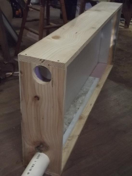 I found I had
a 3-1/4 inch hole saw, and PVC pipe that outer diameter as well. A
building supply store had the matching 90° elbows. So I picked that
size for the uncompressed air ducts through the wall.
I found I had
a 3-1/4 inch hole saw, and PVC pipe that outer diameter as well. A
building supply store had the matching 90° elbows. So I picked that
size for the uncompressed air ducts through the wall.
Future Vision
Obviously many would have these units installed in their
homes to
replace older, energy gobbling heaters, and just as obviously, there
would be similar units designed for air conditioning in warmer climates.
But it also occurred to me that the air intake and outlet
pipes could just as well go through a window with a cover if one was
reluctant to drill big holes through an outside wall.
So ultimately we will probably see 'portable', 'retrofit'
production units: single piece, plug-in OLAHPs with all three main
components in one housing, supplying perhaps 3000 watts of heat with
300 watts
of electricity at freezing temperature outdoors. Bring it home from the
store, drag it into the house
(it will inevitably be bulky), connect the two pipes or
flex hoses through the window fittings, plug it in and go. Not quite as
simple as
a plug-in resistance heater, but not needing professional installation.
Of course, first I need to demonstrate that it works. The
theory certainly seems good. Condensation and water freezing in the
pipes,
especially where the air exits colder than outdoors, is probably going
to be
the toughest issue.
If my six finned pipes don't passively raise the incoming
air temperature enough to get high coefficient of performance (COP) for
3000 watts heat or whatever
amount is required from the system, some larger or longer or more
effective heat
exchanger pipes would, because the same amount of air as comes in goes
out - the exchanger need only reverse their relative temperatures, or
as nearly as feasible.
With a theoretical potential heating COP hitting 20 or
more, if 10
isn't attained, maybe it'll only be COP 7 or 8. OTOH, maybe carefully
designed production units will achieve COP 12 or 14 in freezing weather
- and in weather above freezing but where heat is still needed?
Better Peltier Coolers Project
Well, duh! I searched AliExpress for "nitride ceramic" and came up with
a number of choices of aluminum nitride, .6 and 1mm thick wafers, for a
fraction of the price I paid. Many were quite small and had a hole in
them - they were intended as heat sink insulators for power
transistors. Wow! How could these have made it into power electronics
but not into the absolutely most valuable place for them: Peltier
cooler modules?
I came up blank before, but I did a web search again, this
time on 'nitride ceramic peltier' and came up with a couple of hints
and a company that actually seems to have aluminum nitride Peltier
modules: tec-microsystems.com . They have obviously taken this project
much farther than I ever could. Instead of being the usual 40x40mm
& "12V", they started off 'miniscule' (6x6mm) and worked their way
up to 'tiny' (7x14mm). The ceramic was just .5mm thick instead of about
1mm. Voltages were way lower obviously due to the small sizes and hence
small numbers of thermocouples (known as "pellets"). Thicknesses went
from 1.4 to 2.6mm. (I don't know what the advantages of thinner are,
but the thicker ones had higher "Qmax" ratings.)
They also have aluminum surfaced modules. I had thought
these would be impossible or impractical to make. They have some sort
of flexible, electricly
insulating adhesive inside holding the copper 'buses' (thermocouple
interconnects) to
the aluminum plate. Because of the flexibility they claim a million
heating-cooling cycles of operation, and one of my two main
disappointments
(other than poor overall cooling performance) has been the notably
short life
of the regular modules.
These don't seem to be available from any of the regular
dealers AFAICT - only on their website. I hate to imagine the prices.
(In fact, I think I searched the usual electronic components suppliers
in my previous search rather than a full web search, so I didn't find
makers who don't go through them.)
But if I'm going to do anything now, I'm buying. I was
only going to try to make them myself because previously I couldn't
find anyone who was already making them. (So much for the aluminum
nitride disks I just bought!) I think I could do no better "research"
than to phone them and ask a few questions.
- Which type has the best thermal specs?
- What is the thermal resistance of the flexible adhesive in the
aluminum Peltier modules compared to aluminum oxide ceramic?
- Are they pure aluminum or an alume alloy?
- How much better are aluminum nitride modules than aluminum oxide ones?
- What would you recommend to get a "best performance", that is,
greatest temperature drop, in a Peltier camping cooler?
- Prices
I emailed instead of phoning and asked these questions.
There was a very detailed reply and he said the answers deserved a
book. I may recur to this subject in more detail another time. To
summarize some key points, one consideration I had been especially
ignorant about was the coefficients of temperature expansion (CTE) of
the materials used. One reason for the short life span of typical
Peltier modules is that the CTE of aluminum oxide is half that of the
alume alloy heatsinks they are attached to. (And, I would expect, also
and more criticly,
different
from the copper circuit traces and thermocouples inside.) One reason
tec-microsystems.com's ones with an aluminum outer skin and flex
insulation inside last so long is that the CTE matches that of alume
heatsinks. (And surely, the flex insulation within lets the 'pellets'
inside adjust position minutely with temperature.) Beryllium oxide is
toxic during manufacture, especially the dust, but okay as a finished
product. He said
"Manufacturers like Marlow (II-VI) use it for TEC manufacturing." I
haven't looked up "Marlow".
The aluminum nitride ones do have the best thermal
performance specs of those TEC Microsystems make, with very high
"Qmax"es for their
sizes, but their CTE is only about 4
where the oxide is ~7.1, so they are a worse match for alume heatsinks.
The more power you try to put through the Peltier, the more the thermal
resistance of the skin matters and hence the worse the temperature
drop/rise through it. The aluminum nitride ones can have higher power
in a smaller space.
When the Peltier is turned off, they will all have about
the same heat transfer between the hot and cold sides because the
bismuth telluride (BiTe) thermocouple pellets inside have
substantially lower heat transfer (1.5?) than the surfaces (20+) and so
are the
deciding factor.
Every installation needs to be individually evaluated to
find the best match. He said it's hard to make a Peltier camping cooler
with adequate heatsinks, so it's no surprise that they cool better at 9
or 10 volts than 12 by keeping the hot side temperature from rising as
much.
I was thinking higher voltages didn't help when I used the
fabulous copper heatsinks either, but reviewing TE News #181, I see I
didn't actually try higher than 10.5V - and that's where it got
coldest. I should have tried higher - and still should.) The method of
attachment to the heatsink is also important. (Hence my recently buying
"the best" heatsink compound, also yet to be tried. But when I was
using flex graphite "gasket"
instead of heatsink compound, I was probably allowing the heatsink and
Peltier to adjust separately for CTE.
Since graphite has fabulous thermal conductivity in the
plane (as opposed to across the plane as I was using it, which is good
but only 'pretty good' by comparison), I wonder again if heatsinks
laminated from layers of flex graphite bolted together with their edges
contacting the Peltier might not make the best Peltier heatsinks of
all. It would also have low CTE I expect, to better match oxide/nitride
skin CTEs, perhaps giving them longer life? And it's cheap compared to
copper. It's also something worth trying, and surely easier with the
aluminum nitride
Peltiers owing to their small size. I'll probably get a few and test
both the aluminum and the aluminum nitride ones, and make a graphite
heatsink to match, which may not need heatsink compound at all. When
I'm not busy, ha ha.
Cabin Construction
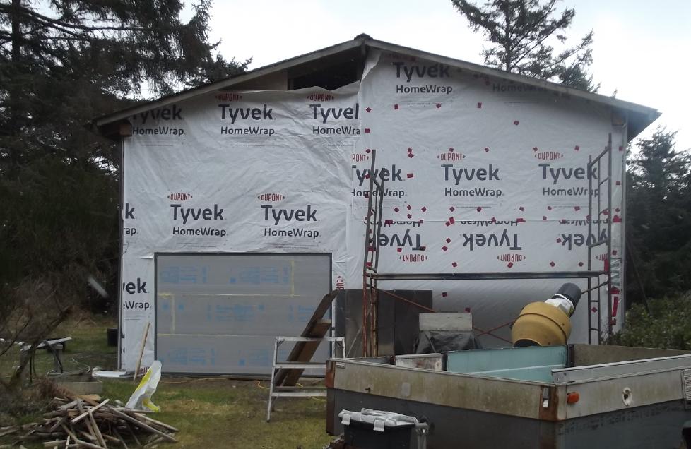 Fat garage door fitted on the
cabin
Fat garage door fitted on the
cabin
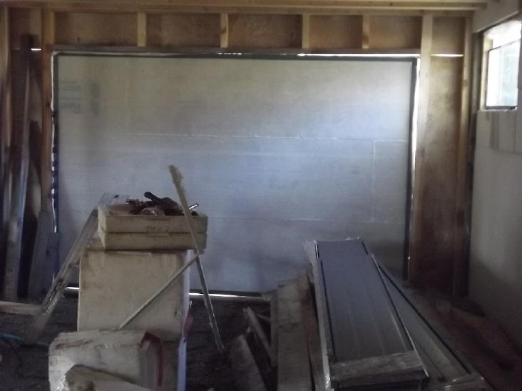 I glued the styrene foam pieces of the garage door together with "gap
filler" foam. The inside got an epoxied coating of light polypropylene
(PP) cloth. It's rather transparent. The outside is to have "galvanized
air duct" sheet metal (new metal from the refuse station). Owing to
hurting my "tennis elbow" yet again in pounding out the bends with a
wooden hammer, as well as the cold weather, I haven't finished
flattening it or tried to put it
on yet.
I glued the styrene foam pieces of the garage door together with "gap
filler" foam. The inside got an epoxied coating of light polypropylene
(PP) cloth. It's rather transparent. The outside is to have "galvanized
air duct" sheet metal (new metal from the refuse station). Owing to
hurting my "tennis elbow" yet again in pounding out the bends with a
wooden hammer, as well as the cold weather, I haven't finished
flattening it or tried to put it
on yet.
I had to grind away a bit of concrete and plane down the
somewhat warped board above to get the door to fit.
I've decided to hinge it to open outward instead of
making a track and having it "roll" up into the ceiling - simpler. I
only think I can
get away with this on such a wide door because it's so lightweight.
(And I really need to get the metal siding on the wall before a wind
rips the Tyvec off!) If only the weather would warm up above freezing!
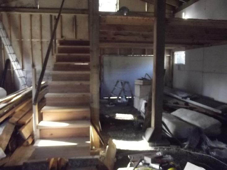 Earlier in the
month I had made and put in stairs to the room over the garage section.
The mill didn't have 12 foot 2 by 10s and I used 10 foot stringers.
They turned out steeper than I had expected and I put up a temporary
railing. Steep stairs with nothing to grab are very dangerous.
Earlier in the
month I had made and put in stairs to the room over the garage section.
The mill didn't have 12 foot 2 by 10s and I used 10 foot stringers.
They turned out steeper than I had expected and I put up a temporary
railing. Steep stairs with nothing to grab are very dangerous.
(The first step is really big until I get the downstairs
floor put in.)
 3 x 5 foot
landing from above. It's one stair step below the floor. ...Needs
safety railings! (Not to mention two whole walls and a door on the
room!)
3 x 5 foot
landing from above. It's one stair step below the floor. ...Needs
safety railings! (Not to mention two whole walls and a door on the
room!)
In
Passing
(Miscellaneous topics, editorial comments & opinionated
rants)
Scattered
Thots
* Someone sent me a link to a video on Bitchute where the maker was
complaining about various sources of electrical noise causing tinnitus.
He especially said that since 2020 when all the "5G" equipment was
being installed everywhere, way more peoples' ears have been ringing.
Maybe it's caused by ANY AC power at any frequency, not just 60 Hz
power lines? This would agree with my original supposition from long
ago (from hearing what appeared to be morse code) that it was from
radio transmissions. At my present location so close to the 14,400 V AC
power lines, any radio signals are drowned out by the loud piercing
tone.
"The Root Cause of Tinnitus - Can we hear electricity?"
https://www.bitchute.com/video/FYei2fN7PZvd/
Later I read a comment under a Youtube video ("WHY THESE
MASTS ARE POPPING UP EVERYWHERE...") about measuring signal strength of
5G, that "My neighbors claim they started hearing annoying tinnitus
like noise even before realizing there was a new mast in the
neighborhood."
* Another commenter under the same video mentioned people getting
headaches, itchy, prickly skin, and more. He said that at one mast he
felt head pain and "pressure" near it. He measured the field strength
and found it was way above Swiss and German legal limits. And he said
he saw a lady go out of her way to walk across a muddy field to a bus
stop to avoid the area of the antenna. And in Daajing Giids someone
said that everyone in the few houses right around a (5G?) mast had
cancer including himself.
Electricity has grown around us over the decades with
hardly a thought to the fact that the fields travel right through us
and the long term - or even the more subtle short term - consequences
of that. There is no question but that electric fields of all kinds and
frequencies warrant far more study than they have ever had.
* I usually walk on the beach at lower states of tide when the big,
flat sandy area is exposed. I should know better than to walk up near
the high tide lines - sometimes I come back with all the bottles and
bits of
plastic waste I can carry. (And there's virtually never a plastic - bag
- to put it all in!) I understand many remote beaches where no people
live to
cart it off are just awash in plastic.
One day I went down with a 5 gallon bucket to get drying
kelp for garden fertilizer. I ended up with half a bucket of plastic
and a big, heavy chunk under my other arm. And some kelp mixed in - all
to be separated again. A couple of days later I repeated that, and had
to leave a very big plastic float behind for later.
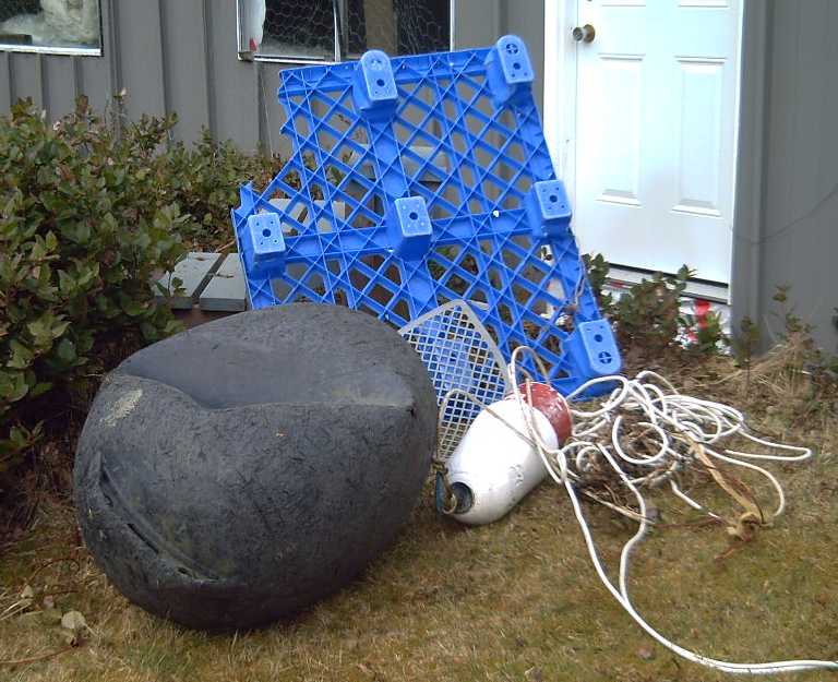 Some big beachcombing finds
including the
aforementioned float
Some big beachcombing finds
including the
aforementioned float
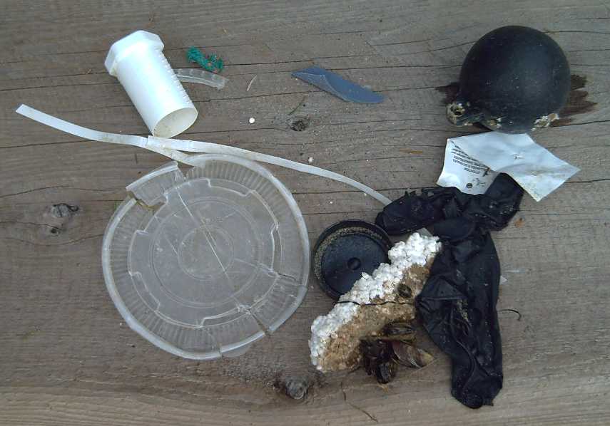 and the day's handful of plastic
bits (the hand
not dragging the float)
and the day's handful of plastic
bits (the hand
not dragging the float)
Hmm, no drink bottles or caps today
NOTE TO THE WORLD: I'm tired of picking up your plastic! The water is
no place for it. If it has no other use, remember that most "single
use" plastic, especially PE (LDPE, HDPE, UHMW, plastic bags, many food
containers... also PP) is a simple hydrocarbon that burns the same as
natural gas or propane: no smoke, no ash or residue, just water vapor
& CO2. (It burns hot - just burn a little at a time. But it doesn't
really save much firewood - maybe if I cut up the big pieces with a
saw!)
* My microwave oven had such a dark grill on the door I really couldn't
see inside. I thought there was a cup of coffee in it that I had placed
there earlier, but I had already taken it. I started it carelessly
without making sure - empty - and
in a few seconds there was a sound and a bright flash. I shut it off.
There was a burned spot on the side. I used it one more time, but then
there was another flash and not knowing much about them, I decided I
had better discard it. Just once, run empty, was a terminal mistake.
I bought a new one. Same brand, even more obscure window.
Worse controls and no reminder signal - in fact no indication at all
that something has been cooked and is still inside. Sigh! (Why aren't
there buttons to turn the light on to see inside? They have the light,
they have a keypad -
how hard could it be?)
* Some have taken to calling birds "avian dinsoaurs" and actual
dinosaurs "non avian dinosaurs". To me this seems like an absurd
mischaracterization.
At least one long extinct line of birds also evolved from
dinosaurs, as did marine and avian reptiles. Dinosaurs also evolved
into mammals more than once, the last time creating the much superior
placental mammals. Dinosaurs themselves
evolved during the Triassic from other early reptiles or amphibians
(frogs & toads; lystrosaurs), which evolved from fish, which
evolved from lower life forms.
If we follow this logic that everything is a dinosaur,
then mammals are also "non avian dinosaurs" of some sort - but also not
extinct. Amphibians must be "hybrid marine dinosaurs" and fish
"unevolved marine dinosaurs".
My point of course is that birds are not dinosaurs any
more than mammals are, or any more than adult frogs are "land dwelling
fish".
* Many negative trends, directions and events that would have been
unthinkable in decades past have been, are, and surely will continue to
be, taking place. I have documented some of them in past issues because
the mass media, now all owned by a very small clique and all in unison
either doesn't cover them at all or presents fictitious views of them,
repetitiously and often word for word alike from every outlet, to
direct the hearer's thoughts in a particular direction and fit a
particular agenda.
We might think of the Urantia Book's well known
example of the image of a filthy, brutish caveman wielding a club -
obviously a savage aggressor who deserves our hatred. Then we broaden
the picture and see there's a woman and child behind him, and a hungry
sabretooth tiger in front. Suddenly we admire him and are sympathetic
instead - same brute! Often the present day mass media only shows us
the first image to arouse our fear and indignation.
It is well to be aware of major civilizational trends and
ulterior agendas as they continue to arise and unfold, and to
search for one's news from multiple sources and broader viewpoints,
mostly
available on line from some of humanity's deeper thinkers who are
looking at broader pictures. The unwary are too
often ensnared by the unscrupulous. Scams abound.
But dwelling on the problems is of little value except
insofar as creative thought may help generate solutions to them.
Citizens should be involved in societal decision making processes, but
in the present era channels through which to do so are are few,
inadequate, and most often negative and "after the fact" - "protests"
coming after politicians with no prior societal feedback have already
made decisions. Being aware of problems, it's better to keep one's
thoughts and actions focused more on the positive side. Negative
thinking and actions (such as protests and demonstrations) tend to
generate negative results and positive thinking good results. And it is
the little things that each of us individuals does during our day that
aggregate to make the whole world a better or worse place. (Remember
that when you think "It doesn't matter!")
IIRC it was Buckminster Fuller who said that to change a
system, one must first envision a new and better system that makes the
present one obsolete. That requires awareness of the benefits and the
inadequacies of the present system -- and then positive creative
thought.
* Hmm... the protocols that run the internet were originally built on
programmers' ideas mutually submitted by "RFC's" - "Request For
Comment".
Nothing was "set in stone" without all the programmers first having had
a chance to provide feedback. Could legislation be subjected to a
similar public prior review process that might modify poorly thought
out or cancel ill advised programs before they are enacted? Proposed
legislation could be posted on a web site for public purview. (Today
governments usually seem to legislate in a near vacuum of public input,
and hence are easily swayed by vocal or wealthy special interests,
ultimately leading to corruption.)
If it would be chaotic to have a zillion individuals
commenting, perhaps legislative proposals could be submitted to (or
simply perused by) citizen "committees", "teams" or "think tanks" for
well conceived, clearly voiced comment as agreed by the group? ...And
then of course, perhaps such "ad hoc" - or perhaps formally
constituted, qualified and recognized citizen organizations - probably
concerned with a particular topic area, could also themselves research
and propose legislation that would be socially valuable but which isn't
high ranking in politicians' thoughts and agendas? (Perhaps they would
be vetted/certified by some organization outside immediate government,
recognized as the "citizen committee qualifying organization"?)
ESD
(Eccentric Silliness Department)
* They say Samuel de Champlain "founded" Montreal, as if perhaps he
had made it in a foundry. "Found" is already past tense. For Champlain
to say "I hereby found Montreal." is nonsensical because it wasn't
there to find, so to use "founded" in present tense, we must find a
different form. So he must say "I hereby finded Montreal" or "Today I
am findeding Montreal."
But when Aleric went to sack Rome, it was already there
and he
found it. (It wasn't hard because "All roads lead to Rome".) However
when he left, Rome was no more. Aleric was the "unfounder" or
"defounder" of Rome. While defindeding Rome, Aleric and his horde
were looking for food. But (at least by the time the city surrendered
and opened its gates) they were shocked to find there was no food in
Rome. Thus in his motive for the confindering of Rome, Aleric was
dumbfounded.
Luckily neither Aleric nor Champlain spoke English. Their
languages probably didn't have these particular grammatical
idiosyncrasies to confound them.
* As seen from BC
- Near East: Alberta, Saskatchewan
- Middle East: Ontario, Quebec
- Far East: Labrador, Atlantic Provinces
- Beyond That: Made in China
"in depth
reports" for
each project are below. I hope they may be useful to anyone who wants
to get into a similar project, to glean ideas for how something
might be done, as well as things that might have been tried, or just
thought
of and not tried... and even of how not to do something - why
it didn't
work or proved impractical. Sometimes they set out inventive thoughts
almost as they occur - and are the actual organization and elaboration
in writing of those thoughts. They are thus partly a diary and are not
extensively proof-read for literary perfection, consistency,
completeness and elimination of duplications before
publication. I hope they may add to the body of wisdom for other
researchers and developers to help them find more productive paths and
avoid potential pitfalls and dead ends.
Electric
Transport
Miles Truck Drivetrain
The variable torque is to be controlled by what is essentially a large,
low speed generator with the magnet rotor spinning on the planetary
body and the "stator" spinning on the input gear, which is also the
motor shaft. Where I used a small number of turns of thick wire in the
12 inch "improved Piggott alternator", I want this 10 inch one to go
readily up to about 80 volts to put its juice into the "72 volt" Miles
truck battery. (Let's see... about 75 turns of #15 wire?)
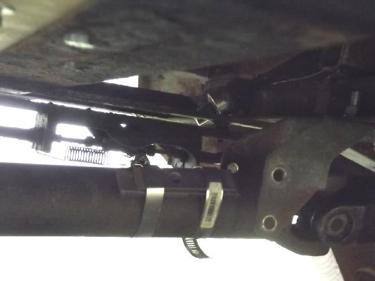 [18th] Whether
or not I do the new version of the variable torque converter, the
vibration in the drive train has to go before it can be used on the
street, much less on the highway. I had to drive the truck out of the
garage to make floor space (for epoxying my new garage door for the
cabin),
so as I've been meaning to do for some time, I put two hose/pipe clamps
onto the rear driveshaft and clamped on a piece of steel bar (150g)
because
it's slightly off-center at the front and so out of balance. (Oh how I
wish I had kept the original transmission, or at least the end "slip
spline" piece that fitted properly into the driveshaft! That's why I
have so much junk around - just in case. In this case I didn't keep it.)
[18th] Whether
or not I do the new version of the variable torque converter, the
vibration in the drive train has to go before it can be used on the
street, much less on the highway. I had to drive the truck out of the
garage to make floor space (for epoxying my new garage door for the
cabin),
so as I've been meaning to do for some time, I put two hose/pipe clamps
onto the rear driveshaft and clamped on a piece of steel bar (150g)
because
it's slightly off-center at the front and so out of balance. (Oh how I
wish I had kept the original transmission, or at least the end "slip
spline" piece that fitted properly into the driveshaft! That's why I
have so much junk around - just in case. In this case I didn't keep it.)
I went around the driveway loop and it seemed
considerably better. Next I clamped another piece on the other side
(30+g) and it seemed better. I found two pieces about 110g and replaced
the 150g, also removing the 30g. That seemed best, fairly smooth to a
higher speed, but at a certain speed a big vibration started up.
I couldn't help but think
that this must be in the motor shaft before the planetary, which turns
five times faster than the driveshaft. But why? It's a long shaft, but
nothing there is out of balance (AFAICanSee) and there's a steady
bearing part way and it ends at the clamped-on planetary gear. What
could be rong?
[20th] I had made the back end of the housing mount "springy" so that
it could shift a bit for any misalignment. I took another video and I
could see the whole housing vibrate. I stuck a wedge in that held it.
It seemed a lot
smoother until that fell out. That seems to be the problem. I need to
attach the rear end of the box solidly to the frame.
Other
"Green"
&
Electric
Equipment Projects
Open Loop Air Heat Pumping ("OLAHP")
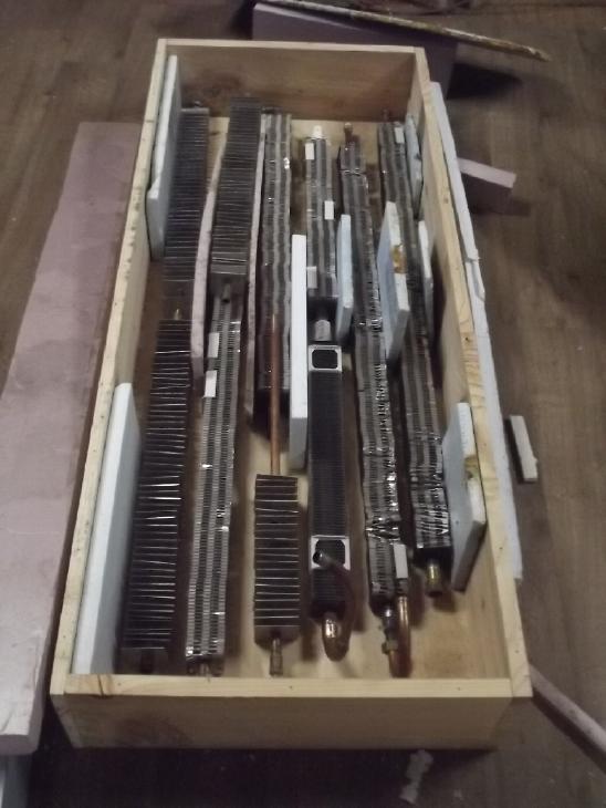
Indoor-Outdoor Air Heat Exchanger
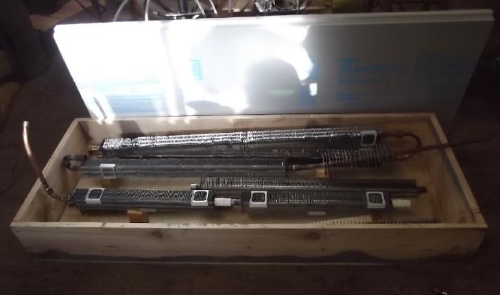 I put together
the box then placed the finned pipes
inside. I wished I had made it taller. 30 inches instead of 24 would
have made it much easier to fit the pipes in, all in a vertical
zig-zag, and
it wouldn't have needed to be so deep front to back. Instead, at least
one pair of pipes is going to have to be fitted behind and in front.
OTOH 24 inches is the tallest that can fit between the baseboard heater
that I never use and the window on the dining area wall.
I put together
the box then placed the finned pipes
inside. I wished I had made it taller. 30 inches instead of 24 would
have made it much easier to fit the pipes in, all in a vertical
zig-zag, and
it wouldn't have needed to be so deep front to back. Instead, at least
one pair of pipes is going to have to be fitted behind and in front.
OTOH 24 inches is the tallest that can fit between the baseboard heater
that I never use and the window on the dining area wall.
[19th] I had been shopping around for
some way to connect the pipes. The "zig-zag" arrangement needed very
sharp turns. I had some 3/4 inch PVC pipe which I had found in 2020
that I could heat with an air gun and fit onto the 3/4 inch copper
pipes. I wished there was a plumbing store where I could buy PVC pipe
fittings. I bought some hydraulic hose thinking it might bend sharply
enough without kinking. Finally I got my bucket of plastic plumbing
bits from storage and to my amazement pulled out enough elbows and
pieces to do the job! I should have looked there first.
[23rd] I
started putting insulation in the box. I really hadn't reckoned with
just how much room two inch insulation would take up on every side. It
seemed too shallow to do front and back unless I had almost no
insulation between the pipes, and still almost none between the rows. I
ended up redoing it: no insulation at the top where it would be closest
to room temperature and only one inch at the bottom. That provided
three more inches vertical space to put all six rows in verticly, none
front and back - still with very minimal insulation between rows. On
the plus side, the front and back insulation, the large faces, could
both be two inches, R10, leaving just 3-1/2 inches width air space for
the 2-1/4 and 2-5/8 inch square pipe fins.
[26th] About the outer
holes for the non-compressed air? I found I had a 3-1/4 inch hole saw.
That would be much nicer than roughly cutting a hole out with a jigsaw.
I drilled the two holes in the box... but what would fit into them? I
looked on a shelf with pipes. I knew I had 4 inch PVC. Lo and behold,
hiding inside that was a 3 inch piece. It was a perfect fit for the
holes I had just drilled. I might have a really hard time finding an
elbow and other fittings, but at least something went into the box.
(Hmm... If I cut the pipe at 45° and glue it on the other way, it
would be a 90° corner. Worst case choice.)
I'd have done more work on it but it was too cold. Maybe I
should do the test install in the workshop instead of in the kitchen
& dining area? That also would have the advantage of not having a
fridge periodicly at random adding other heat into the space, which
made good measurements tricky in 2020.
[27th] I unsoldered and soldered
fittings onto the finned pipes in order to let me connect them the way
I want in combo with attaching PCV elbows and pipe bits by heat gun.
3/4" PVC pipe is a bit to small to go over 3/4" copper pipe... unless
you heat it. Then it slides over and shrinks again as it cools, making
a tight fit. A pipe/hose clamp makes sure of it. Same with 1/2" and
1/2". Using plastic fittings at al the bends creates thermal barriers
to stop heat transfer along the copper pipes. (FWIW)
Then I went into town. By some miracle the building supply
store had 3" PVC elbows and I found them. It looked like they only had
4" PVC, all laid out in a bunch of shelf trays, but as I was about to
give up, I spotted a box of 3" fittings across the aisle, all jumbled
together. I'd guess they aren't getting any more. (No discount, tho -
12$ each!)
Cabin Construction
Styrene Foam Garage Door
At some point
I put in the stairs, then concentrated on making the one-piece pull-up
garage door.
At some point I glued the
extruded styrene foam sheets together with expanding "gap filler" spray
cans. (I remembered this worked well with my "superinsulated Peltier
fridge" around 12 years ago.) With the 2 inch foam the insulation value
of the door is R10. Pretty good for a door!
[20th] Yesterday & today I epoxied white polypropylene (PP)
"landscaping" fabric onto one face of my extruded styrene foam garage
door, which I had finally glued together with "gap filler" spray in
recent weeks. (I finally finished off a ten year old gallon of "West
System" epoxy and its hardener.) I suppose I should paint it.
For this I drove the electric truck outside and used the
heatable and relatively clean garage. I did my best, but it didn't turn
out perfectly. As I suspected, everything shows through the thin layer,
even the printing on the styrene. The plastic picked up some spruce
needles and things by static and I missed some little bumps of the "gap
filler" foam that I glued the sheets together with. They're all under
the PP, visible and making bumps. But overall pretty good effect. I
used my usual technique of putting the left over epoxy in the freezer
overnight so it wouldn't set and I could continue in the morning with
what was left and the same roller.
My ideas for how to attach the door are still rather vague.
[25th] I took the door from the heatable garage to the cabin and set it
in place to check the fit. I had to cut the "overhang" part off the
bottom. It wouldn't quite go in as the outside frame wasn't quite
square. I figured I'd have to cut the door down a bit.
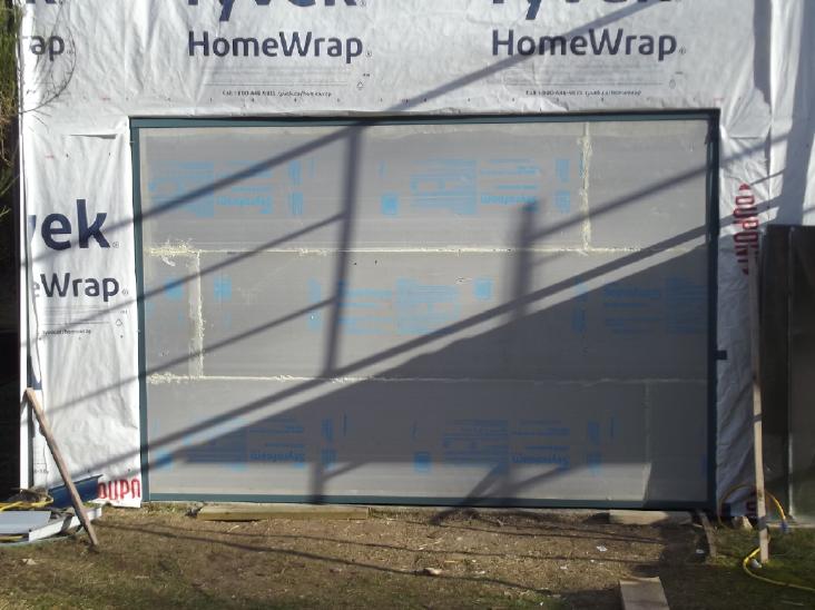 [26th] I
looked at it again and decided to change the frame instead: I ground
off some cement where it rose up a bit at the bottom in one corner, and
I planed off some wood from the 2 by 4 along the top, which was warped
and bent down a bit in an area in the middle.
[26th] I
looked at it again and decided to change the frame instead: I ground
off some cement where it rose up a bit at the bottom in one corner, and
I planed off some wood from the 2 by 4 along the top, which was warped
and bent down a bit in an area in the middle.
Then I decided it would be
easier and maybe better to hinge the door, opening out to the outside
wall instead of having it roll up into the ceiling. It's very wide for
hinging but also very lightweight. But the weather turned freezing cold
and I haven't wanted to work outside, so there it has sat.
Electricity
Storage
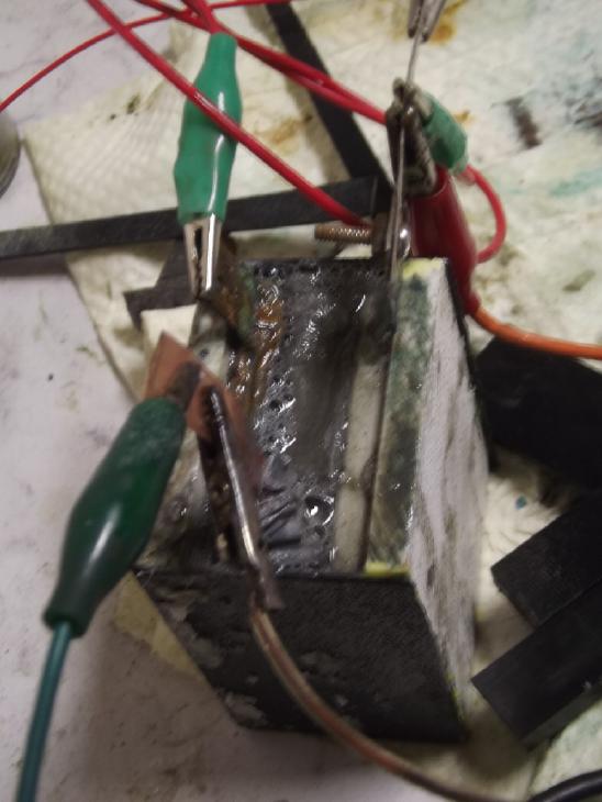
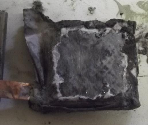
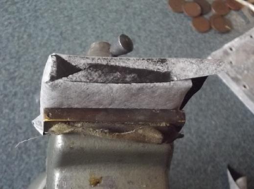
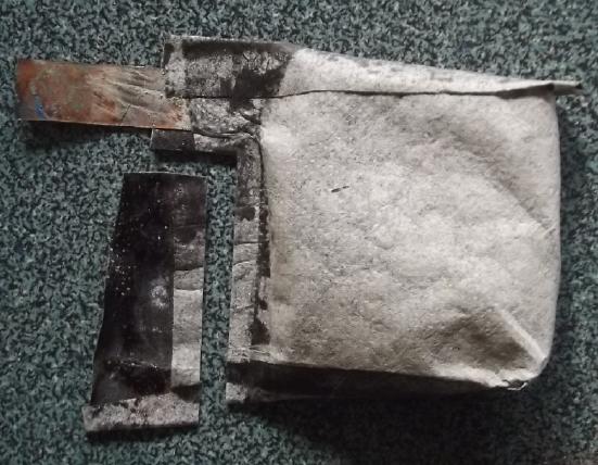
Everlasting Copper-Zinc Cells with Plastic Pocket Electrodes
Blended Copper-Nickel Hydroxides Positive Powder & Electrode
[6th] I decided that if copper by itself didn't want to recharge -
except it seemed to to some extent as contained in cupro-nickel sheets
- I should try and make a mixed nickel-copper oxide similar to the way
I had for so long been trying to do with nickel-manganese oxides (AKA
nickel manganates). Except now I know to dissolve them in acteone to
form into epitaxial crystals as the acetone evaporates, and I realize
that I should only charge to copper oxides voltages, not high enough to
turn the nickel component into nickel oxyhydroxide.
I decided to make the ratio 60:40 copper:nickel, a 3 to 2 ratio,
without bothering to
try and count copper and nickel atoms. So with 21 grams of copper
hydroxides in a jar, I would try something along the lines of:
Ni(OH)2 - 14 g
Mixed copper hydroxides (with graphite) from my own previous electrodes
- 21 g
A bit more graphite - .5 g (Actual: .6 g. The scale settled .1 g above
where it read when I finished adding. Grr! Still, not far off.)
I measured them into a 100cc beaker and added acetone. As
I stirred the hard lumps disintegrated, the colors blended to dark
gray, and
it made a thin paste. I put it on the hotplate at the "60°" mark to
evaporate the acetone faster and hence presumably grow smaller crystals.
In a while it was "burping" occasional bubbles that came
up from beneath, and there was a thin layer of liquid on top. I poured
off most of this little bit of excess. By bedtime it seemed powdery
again and I turned off the heat.
Of course mixing with a substantial percentage of nickel
hydroxide notably dilutes the copper hydroxides with their fantastic
amp-hours density. Making cells that work cycle after cycle without
deterioration takes priority! [Later note: totally unnecessary]
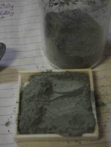
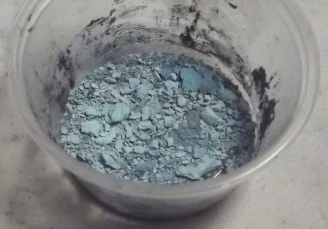 Sky blue copper II hydroxide
[Cu(OH)2] made by
electrolysis in sodium nitrate solution
Sky blue copper II hydroxide
[Cu(OH)2] made by
electrolysis in sodium nitrate solution
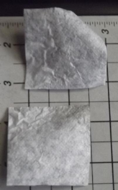
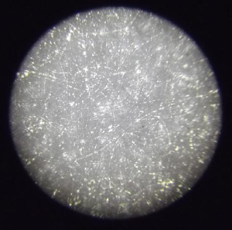 Parchment paper under microscope:
very fine
holes
Parchment paper under microscope:
very fine
holes
[Later note: actually the best]
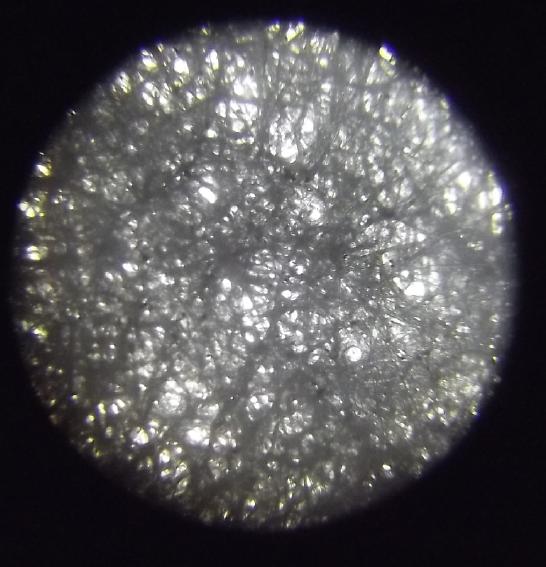 Coffee Filter Paper
 Used coffee filter paper showing
holes (lit
from behind)
Used coffee filter paper showing
holes (lit
from behind)
where powder would have been getting through. It's too coarse.
 Cone coffee filter: very coarse
and fuzzy.
Cone coffee filter: very coarse
and fuzzy.
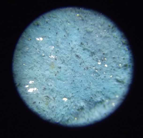
 At some point I made a zinctrode.
Compacting a
zinc "briquette" works poorly.
At some point I made a zinctrode.
Compacting a
zinc "briquette" works poorly.
[7th] The powder still smelled a bit of acetone in the morning. I put
it on the woodstove for a couple of hours to drive off the remnant. In
the meantime I printed a new electrode box, this time mirror image to
have the terminal on the other side.
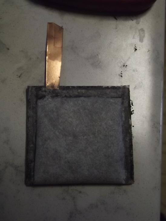
I cut & put in a coffee filter paper then 9.30 grams
of powder, filled in loosely to the rim of the box. I scrubbed the used
current collector and set it in, then the box back. When I pressed it
down pretty heavily with my hands it went down until it was slightly
recessed in the box. Then I bleached it in a jar lid of water and a
tablespoon of bleach for ten minutes. I figured the liquid would soak
into the dry electrode so I didn't bother to stir it. After that I
rinsed it in the same lid with water, but I agitated it because it was
already wet and the liquid might not circulate very well. All this gets
out any remnant sodium nitrate, too. ...and some grains of the powder.
I reglued a bit of the back that wasn't stuck. I could see powder
drifting out there.
The cell started off saying .151 volts. (Isn't bleach
supposed to charge it? Or was that hydrogen peroxide?) Usually the
voltage starts rising or drifting, but it sat exactly there. It started
charging at just 52mA with the power set to 1.5V. 47mA after 10
minutes. 12:27, 38mA. Voltages briefly off charge, O/C and 50Ω load are
rising. So it seems to be charging.
12:09: 52mA
12:11-12:17: 47mA
12:27: 38mA, 1.1V, .86V (Ante Meridian until ~12:48 here)
13:32: 25mA, 1.2V, .97V
As it got a bit more charged I changed the procedure. Instead of very
short and unmeasured times, I paused the charge and measured the open
circuit voltage after 30 seconds, then immediately turned on the load
and read the voltage after 30 more seconds. Once again, at these
disappointing charging currents, it's going to take a long time to get
to a few amp-hours worth of charge.
15:32: 16mA, 1.261V, .972V
15:52: 16mA, 1.245V, .981V
16:22: 16mA, 1.262V, .986V
17:54: 12mA, 1.290V, .944V Ouch, this doesn't look good! New
tack: switching to 1.8V charge. Started at 72mA, soon down to 35.
Higher and higher open circuit voltages, lower and lower
drive voltages and currents... I suddenly realized the problem was
nothing I had been thinking about. The CuNi current collector was
becoming higher and higher resistance, losing connectivity to the
electrode substance!
The back of the box was well glued, but I managed to pry
it off with a small knife without wrecking it. I removed the CuNi
current collector. Resistances didn't seem high on an ohmmeter, so I'm
puzzled. I cut out and installed a graphite foil one. It was much
worse. But it does illustrate that connectivity to the current
collector seems to be the problem. Or at least, something in the
connectivity within the electrode. Maybe it's the powder itself
expanding and losing connectivity, but pushing on the back to squeeze
it against the zinc trode doesn't seem to help at all. Well, I'm
totally frustrated now. I don't know what I haven't tried but I keep
having the same or similar problems over and over again. [Later note:
It was zinc passivation - not the copper side at all!]
[8th] I think it might have something to do with the charging and
discharging. If you run it down to .5 volts with a 10 Ω load, it seems
to strengthen it a bit. Then if you leave it charging at low current
for too long, it weakens it and load voltages drop. There may be some
charge-load cycle that will strengthen it for an initial formation -
which I then hope wouldn't have to be repeatedly done. I think I'll
have to make that microcontroller based automatic battery cycler I've
been meaning to do for so long. When charge current drops to a certain
point, stop charging and turn on the load. When it drops to .5 volts,
stop and recharge. Repeat.
 [9th] I made a zinc
double-face trode. (at last.) I took the old
single-face one out and put in the new one. For the two "plus" end
electrodesI used the "current" copper-nickel hydroxides one and the
previous copper-only one on the other side. I charged this for a while
at almost double the current of the single one, and then ran a 10 Ω
load. Unexpectedly it ran for for 27 minutes from over .7 volts down to
.500 instead of, like 3 or 6 minutes.
[9th] I made a zinc
double-face trode. (at last.) I took the old
single-face one out and put in the new one. For the two "plus" end
electrodesI used the "current" copper-nickel hydroxides one and the
previous copper-only one on the other side. I charged this for a while
at almost double the current of the single one, and then ran a 10 Ω
load. Unexpectedly it ran for for 27 minutes from over .7 volts down to
.500 instead of, like 3 or 6 minutes.
Has the zinc side been
deteriorating? All this time I've considered the problems must be with
the copper side. In charging the cell, the new trode made lots of tiny
soapy [presumably] hydrogen bubbles, since I made it with metallic zinc
powder so there was no zinc oxide to charge.
 Looking at the previous zincode, the face watercolor paper had absorbed
a
lot of copperish 'goop', probably bits of powder escaped from one
electrode after another as I tried new copper electrodes. Or else, the
copper stuff has been dissolving and migrating. (If so that would
suggest the need for a higher pH than the 6.5 it seems to be working
well at. Either way... Like a clogged funnel that won't drain, perhaps
all that powder covering the face was the unsuspected, unexpected and
previously unseen cause of the declining current capacity?
Looking at the previous zincode, the face watercolor paper had absorbed
a
lot of copperish 'goop', probably bits of powder escaped from one
electrode after another as I tried new copper electrodes. Or else, the
copper stuff has been dissolving and migrating. (If so that would
suggest the need for a higher pH than the 6.5 it seems to be working
well at. Either way... Like a clogged funnel that won't drain, perhaps
all that powder covering the face was the unsuspected, unexpected and
previously unseen cause of the declining current capacity?
After charging (?)an hour and more, the cell ran the 10 Ω
load from .9x V down to .50 V in 50 minutes.
[
Later Note: Wikipedia solubility table says
CuOH: .0000007 g/100cc
Cu(OH)2: .0000017 g/100cc
CuOOH: no figure given
Unless CuOOH is greatly different, those really aren't very soluble!
]
[10th] After charging
overnight, oodles of bubbles and I refilled the
water. It ran the 10 Ω load from .9x V down to .50 V in 95 minutes.
Currents were a little higher at a given voltage too. (The 'Charge' -
'Off' - 'Load' switch is crap. (I got ten of these switches off
AliExpress. "15 A, 250 V". They have burned out in every power
application I put one in, and the switch's resistance changes even just
running battery tests in mA! But I digress.)
So:
1 - 27 minutes
2 - 50 minutes
3 - 95 minutes
and by night
4 - 110 minutes
It looks promising!
It definitely seems that
running copper cells down to .5
volts (or so?) after charging strengthens them. This is probably only
in the initial charging. After running a load, charge currents are high
until the current drawn is replaced, then they get slow again. So once
charged and then discharged it's "working" while the portion of the
electrode's substance still in "initial state" doesn't charge very
fast. So it looks like copper probably makes a viable electrode after
all. It just needs special treatment, several or many "forming" cycles,
after fabrication.
Running it down to .5 volts must reduce the copper to the
lowest oxidation level it will achieve - perhaps to metallic copper
particles. OTOH in the electrode mixed with nickel hydroxide, it may
not get quite get to metal. In fact after the discharge it recovered -
eventually - to just 1.05 V. That too suggests the copper's oxidation
state was pretty low, maybe mostly Cu and some CuOH - or equivalent in
the mixed oxide one.
I connected the two "+" trodes only with an alligator clip
leed. That way I could readily disconnect them. While the copper-only
electrode seemed weaker initially, I checked during recharging after
the 95 minute test and it drew current about equivalent to the
copper-nickel one. In a short 10 Ω load test the mixed oxides one held
.85 V after one minute while the pure copper held only .71. (Both
together were .94 V.) This would seem to validate the higher
conductivity of the spinel crystalline structure. But if conductivity
and higher current drive is the only object, perhaps the pure copper
one could be brought up to a higher level with a few more percent
graphite powder, rather than diluting the copper to 60% by adding 40%
nickel substance. Certainly the amp-hours should be higher.
[11th] I didn't have time until afternoon. By then it had been charging
so long that the voltage started out lower, at .85V and rising in one
minute to .90V. But far from meaning the cell was weaker as I had kept
assuming, under 10 Ω load the voltage dropped still more slowly than in
test 4. By ~30 minutes the voltage was equal to that test (.86V), and
from then on, higher. But it only lasted 5 minutes longer. The next
test was shorter: I don't think I recharged it long enough.
5 - 115 minutes
6 - 90 minutes
Short circuit current is only 280mA. This is pathetic and
only 5.6ma/sq.cm of interface. To get to 50 that order of magnitude of
improvement is still needed. A recent try had been over 15mA/sq.cm,
which here would have meant 750mA. What happened?
[12th] After overnight charging the load voltage started even lower,
.75V, but it was soon over .8 and it crept up to almost .85 over the
first six minutes under load. In an hour it was similar to other loads
at an hour. I turned it off there, .64 volts, thinking discharging to
nothing every time might not be strengthening it.
Something I've been noting all along is lots of bubbles
from the negative and having to refill with a bit of water a couple of
times a day or even before or during a load test. It would seem that I
should make the cell housings with lots of room above the trodes for a
water reservoir. Presumably it will stop needing more once it has been
fully charged and if there's a cover over it.
The more I see, the more I realize I have been taking the
problem of separators much too casually. Some kind of membrane? But
what?
If I use a woven PP cloth ("landscaping fabric", "cloth
grocery bags") it will doubtless have holes for powders to seep
through. If I iron it, it will turn into a solid sheet of plastic.
Maybe if I iron a coffee filter into a piece of PP cloth it could make
a good separator that will let ions pass but not powder, however fine.
But it can't be as fine as the parchment paper, which didn't let ions
pass freely enough and reduced current flow.
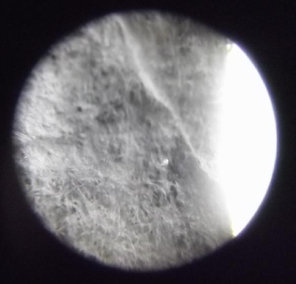
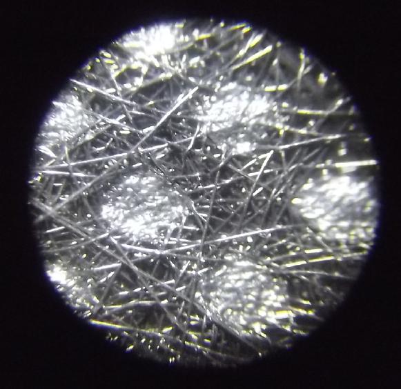
[13th] Under the microscope I see there's a subtle difference in hole
sizes between different brands of basket coffee filters. I'm going to
use white "GK Connoisseur" brand. They seem to have smaller holes than
"Great Value" or (I didn't check any brown filters.)
I also belatedly thought to look at parchment paper under
the microscope. It does have tiny holes and I'm surprised it doesn't
work better. Maybe it too cloggs with nano powders?
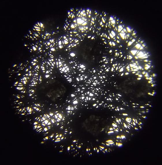
Under a microscope the black PP fabric that looked rather
like
woven cloth turned out to be a random non-woven with regularly spaced
tiny spots fused by heat to make it "solid", if that's the right word -
to keep all the fine strands in place.
 Front Lit
 Back Lit
t
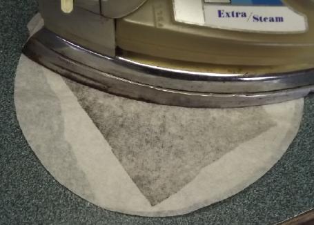 I decided to
make a sheet with PP in the middle and coffee
filter paper on both sides, with the iron set to "Extra Steam"; but I
didn't use any steam. I had to do each face separately because the heat
didn't go through the cloth. Holes showing light through in the
finished "membrane" were small, few and far between, and even so they
had fibers crossing them.
I decided to
make a sheet with PP in the middle and coffee
filter paper on both sides, with the iron set to "Extra Steam"; but I
didn't use any steam. I had to do each face separately because the heat
didn't go through the cloth. Holes showing light through in the
finished "membrane" were small, few and far between, and even so they
had fibers crossing them.
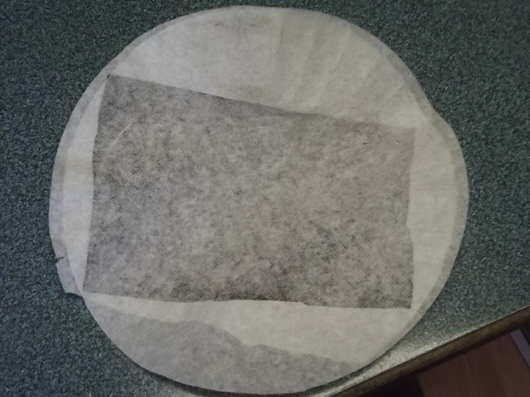
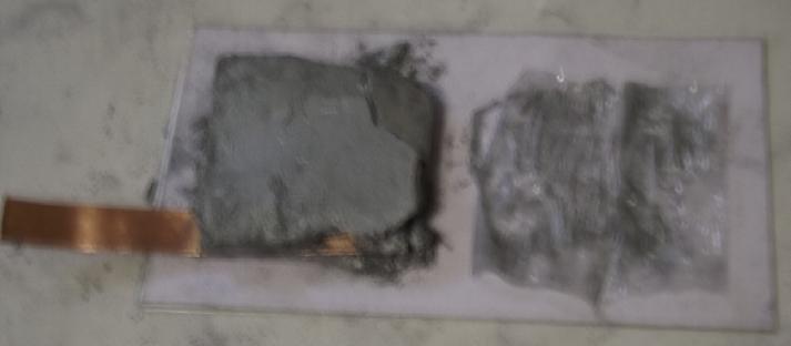
 Pieces cut 50x50mm for new
electrode(s)
Pieces cut 50x50mm for new
electrode(s)
 But even before trying a new electrode, I decided to try
cutting the "clogged" watercolor paper off one side of the zinc and
replace it. It turned out to be "rip" off rather than cut, exposing the
doped cellophane paper. I decided to try it with just the cellophane.
It too was soaked in sodium dodecylbenzenesulfonate (herein "SDBS") and
might by itself stop zinc dendrites. I
put one of the copper electrodes in with it. (Three electrodes were
really hard to get in and out. Two is easier.) It started out around
1.15V and dropped to .9x with a ten ohm load. Short circuit current was
420mA - a considerable improvement with just half the interface area...
under half really, as the paper I peeled away wasn't the whole 50 x 50
mm face. Maybe I need to ditch the watercolor paper entirely?
But even before trying a new electrode, I decided to try
cutting the "clogged" watercolor paper off one side of the zinc and
replace it. It turned out to be "rip" off rather than cut, exposing the
doped cellophane paper. I decided to try it with just the cellophane.
It too was soaked in sodium dodecylbenzenesulfonate (herein "SDBS") and
might by itself stop zinc dendrites. I
put one of the copper electrodes in with it. (Three electrodes were
really hard to get in and out. Two is easier.) It started out around
1.15V and dropped to .9x with a ten ohm load. Short circuit current was
420mA - a considerable improvement with just half the interface area...
under half really, as the paper I peeled away wasn't the whole 50 x 50
mm face. Maybe I need to ditch the watercolor paper entirely?
It started charging at over 100mA which soon dropped under
80.
I had replaced the switch
that had poor contacts, and now
in checking the short circuit current I found another poor connection
that has probably been degrading my readings: the bolt and nut on the
terminal. I tightened it. With charging that current rose to as high as
530mA. If we call it 20 sq.cm of interface that's hit the 25 mA/sq.cm
"good enough" mark, or 1/2 way to the more desirable target of 50 per,
instead of the previous best of 17. If there are no zinc dendrites I'm
definitely ditching the watercolor paper. But any leakage of powder
from the copper side, however slight, will have to be eliminated.
With some charging, discharge into 10 Ω started at a bit
over a volt, 95mA current, and that's with just one copper trode and
half the interface area. Things are looking up!
But I figured powder would leak and clog the cellophane
and so the whole thing would start deteriorating again. And in fact by
later afternoon it wasn't quite as good. So I took it apart. It was
worse than I thought. The cellophane not only was starting to
accumulate gunk, it was ripped across the middle. And the coffee filter
had disintegrated, leaving half the box weave wide open! The watercolor
paper around the zinc was disintegrating too. Apparently I needed to
re-think the whole system of separators, not just the one.
And this in fact was what I saw as the biggest benefit to
the separate tube electrodes in a jar: if powder leaked out, it would
mostly just fall to the bottom of the jar. But I suppose while good for
testing, anything that isn't "perfect" is going to deteriorate over
time one way or another, so "perfection" needs to be achieved.
 [14th] To do
the zinc side, I ironed a coffee filter onto one side of
the PP fabric. I set the iron a little hotter (to "cot") and everything
melted together quickly. The shrinking PP fabric made it curl up. Then
I set it up so I could iron the edges, and glued the PP fabric with the
iron to form an envelope.
[14th] To do
the zinc side, I ironed a coffee filter onto one side of
the PP fabric. I set the iron a little hotter (to "cot") and everything
melted together quickly. The shrinking PP fabric made it curl up. Then
I set it up so I could iron the edges, and glued the PP fabric with the
iron to form an envelope.
It was really a "double" size envelope but I just managed
to get a single sided zinc trode into it. The inward curl grabbed at
the doped cellophane and tried to keep it out. (I should have made a
metal spacer to keep the top wide open.)
When it was in I ironed the top shut and trimmed off the
excess.
Then of course I soaked it in SDBS for an hour - "again"
for the innards but first time for the new cloth/paper cover.
[15th] The cell didn't perform very
well, and even less until I
squeezed the electrodes together. Now I'm starting to think the problem
is the zinc side. I have assumed it will charge from oxide to metal
readily. But the last cell, with the negative made of zinc powder,
worked better. This cell has the same substance, but I've noted that as
it dries out when leaving it on the counter, it seems most of the zinc
turns to oxide in the damp saltiness. And it swells up quite a lot.
Whereas the zinc metal had a ziilion tiny hydrogen bubbles when
charging the previous cell, in this one the water is placid since the
oxide is charging back to zinc. So along with not being very well
charged I don't think the connectivity is as good so the currents are
lower. I could add a conductivity additive like graphite powder, but
it's probably better just to never let all the zinc turn to oxide:
always keep the electrode submerged and never let it dry.
 So... new
zinc trode. Maybe half zinc, half zinc oxide. (And of course half a
percent zirconium silicate.)
So... new
zinc trode. Maybe half zinc, half zinc oxide. (And of course half a
percent zirconium silicate.)
 Breaking up the lumps, on closer inspection they aren't
"mostly oxide". A considerable surface layer is, but inside is more
metal. But when I used the lump pieces it was the oxide that went
against
the current collector. This time I ground these up before reusing them
so there would be some metal throughout. Then I added 5% graphite to
improve conductivity regardless of state of charge.
Breaking up the lumps, on closer inspection they aren't
"mostly oxide". A considerable surface layer is, but inside is more
metal. But when I used the lump pieces it was the oxide that went
against
the current collector. This time I ground these up before reusing them
so there would be some metal throughout. Then I added 5% graphite to
improve conductivity regardless of state of charge.
Looking at the
copper box, the fab new fabric was colored
with blue again. It had to be copper dissolving and getting through
rather than powder getting through cracks. [Later note: apparently
wrong. Holes; powder.]
But when first made,
performance was good even at the lower pH of about 6.5. Two things to
try?:
1. raise the pH to 12 with calcium hydroxide, or
2. block dissolved ions from getting out of the positrode box.
Raising the pH might just mean the same thing happens much
more slowly and the cell lasts a long time. But not 'forever'.
 [16th] So I decided first
to try the latter. A while back I ran across
a pricey 30x30cm sheet of Nafion that I must have bought years ago. (It
seems to me it fell apart in an alkaline environment. Since that's
where I was working, I only used one little piece.) I cut a 50x50mm
square and put it in the window of a new box. I scooped the copper (or
was it copper-nickel?) mix from a previous electrode into it.
[16th] So I decided first
to try the latter. A while back I ran across
a pricey 30x30cm sheet of Nafion that I must have bought years ago. (It
seems to me it fell apart in an alkaline environment. Since that's
where I was working, I only used one little piece.) I cut a 50x50mm
square and put it in the window of a new box. I scooped the copper (or
was it copper-nickel?) mix from a previous electrode into it.
So, now we have dissolving zinc ions trapped by SDBS soap
and dissolving copper ions [hopefully] trapped in a solid box with an
ion blocking membrane in the window. Come to think of it, how could
ions that dissolve and re-solidify, but can't migrate anywhere while
they're dissolved, do any degrading during charge and discharge cycles?
I had to make a new CuNi
current collector - the terminal
had corroded off at about the waterline/top of box. I think it was too
much charging at 1.6-1.8 volts instead of 1.5 or less. (Why can't I get
monel?) I think I'll
extend the plastic of the box to above the waterline around the
terminal tabs. That will also ameliorate the effects of any leakage
around the terminal. (But leakage will still eventually cause trouble,
I'm sure.)
 [17th] The new cell - both
electrodes - put together in the evening,
was disappointing. It started charging at just 25mA or so and overnight
dropped to 11. Discharge into 10 Ω started out hardly above .5 volts.
Well, so much for Nafion!
[17th] The new cell - both
electrodes - put together in the evening,
was disappointing. It started charging at just 25mA or so and overnight
dropped to 11. Discharge into 10 Ω started out hardly above .5 volts.
Well, so much for Nafion!
But it seems to need something if the copper ions want to
migrate. [Later: wasn't the problem] I decided to try the same thing as
in the zinc: SDBS. (After
all, when the ions came out of the copper trode, they seemed to stop at
the SDBS impregnated paper around the zinc.) I just soaked the previous
electrode with the coffee filter/PP separator in the window for an
hour. (Same as before: a tablespoon of SDBS powder in a 200(?)cc drink
bottle of pure water - a refill because it was about empty and dirty
with zinc.)
That was much more gratifying, having similar performance
to the initial performance of previous cells, with several tens of
milliamps of charge current (@1.5V) and 360mA short circuit drive. I
note the zinc wasn't well distributed inside its envelope, having
tended to fall toward the bottom when it was turned upright. It seemed
there was almost none at the top, so it was probably well over
15mA/sq.cm in practical terms. (Now, how do I uniformly fill zinctrodes
when 'briquettes' just crumble?) And putting in spacers to squeeze the
trodes together, more especially to squeeze the zinc envelope,
definitely improved the current drive. I did it while running a 10 Ω
load and the voltage crept up from ~~.85V to ~~.93V as I added more.
Now the 64 thousand dollar
question is, will it continue
to perform, or deteriorate? As well as having many other things to do,
I think I've just about reached the limit of my frustration and
patience with this project for this winter if I don't have a really
working battery or at least a clue why not.
[18th] I pried the last box apart and replaced the Nafion with the new
composite fabric. I cleaned the current collector and sprinkled &
smeared a thin layer of graphite onto the copper substance before
putting the current collector back on. Maybe that will help the CC
connect to the powders better? Then SDBS for an hour.
The zinc is double sided and I put both copper boxes in,
one on each side. The new one initially gave around 330mA sort circuit
current, but after a while of charging was down to 275 or so. The other
one was around 225. Both together were around 425. This suggests that
the zinc side is probably partly responsible for the low currents.
[19th] Discharge voltages and currents dropped with charging and time
again. Two things occurred to me. One was that I had forgotten to
bleach the new electrodes. The second was that 1.5 volts might be too
high a charging voltage for cells that are fully charged at around 1.3
V. 1.6 or more seemed to degrade the CuNi current collectors, but
perhaps there was still something causing a problem at 1.5V? Worth
exploring. I dropped the charge to 1.4V, then to 1.35V. Charging
current didn't drop much. It didn't help. Output voltages/currents
continued to decline.
[20th] I took out the electrodes. I put the zinc in water so it
wouldn't mostly discharge. I dried the copper ones on the woodstove,
then bleached them: each separately, a tablespoon of bleach in a cup of
water for 10 minutes or more.
[21st] Maybe SDBS was the wrong gel for the plus side? I heated a
little bowl of water and mixed in a teaspoon of agar. I put in one of
the copper trodes and let the mix soak in. Then I reassembled the cell
with just the zinc and that one copper. As usual it seemed to be
working okay, but currents were lower. I finally put the other one (now
bleached) in instead.
As the zinc was fuller at the bottom than the top, I pressed the
top of the zinc in a bit with extra spacers and the discharge current
rose notably. Obviously it pays to have the zinc well "squashed"
against its current collector - and I probably haven't got it very well
yet. How can I make a zinc with flat faces if it settles to the bottom
of its "envelope" before it gets into the cell? In fact, I'm starting
to think that's the main problem with the cells.
AHA! The more I think about it, the more sense this makes.
When I opened the big flat cell last month, the zinc metal had largely
turned to oxide and it had swelled from 4-5mm to 7mm or more - 1.5x to
almost double. So as the cell charges the zinc oxide returns to metal
and shrinks, and in doing so with no added compaction it loses
connectivity between particles and to the current collector. So the
more the cell charges, the worse the performance gets - exactly the
symptoms I keep seeing. nothing to do with migrating copper ions. Then
when I push added spacer pieces in, the ever dropping load voltage and
conductivity go up again. So it would seem that the thickness of the
zinc electrodes needs to expand and contract with charging and
discharging. And the copper ones would probably do likewise, except
expand with charge and contract with discharge. But it might not be
even between the two sides.
[22nd] I think I'll try redesigning the electrode boxes so that they
slide together like a cardboard box with separate top and bottom, with
the faces having the mesh, and use them for both electrodes. The layers
will be assembled into the bottom and then the top put on. Enough
material will be stuffed into them so they don't quite close all the
way. Then they'll be stuffed into the cell tightly to keep them
squeezed closed and compacted. Sponge rubber will be placed at one end
to keep them all pressed uniformly together as they expand and contract
a bit with changes of charge state. I think this plan should work - if
the powders don't seep out the edges.
If I keep the boxes lying flat until they're all squashed
into the up-ended cell, perhaps the powder will remain equally
distributed instead of settling toward the bottom like my "no box" zinc
trodes have been doing. I suppose theoreticly the paper wrapped zincs
should be able to expand and contract, perhaps even more easily than
"telescoping" boxes, but I'm going to try boxes in order to get them
square and even. (Hmm... how do I seal around the terminal? need "Flex
glue"? Separator fabric?)
 First, an experiment: take out fixed spacers and put in
some with "weatherstripping" sponge rubber pushing on them and see how
even the discharge voltages and current stay. I accidently left the
cell on "discharge" overnight and it was down to about .12 volts, so
there will be a great deal of charging over the day.
First, an experiment: take out fixed spacers and put in
some with "weatherstripping" sponge rubber pushing on them and see how
even the discharge voltages and current stay. I accidently left the
cell on "discharge" overnight and it was down to about .12 volts, so
there will be a great deal of charging over the day.
[23rd] The sponge rubber seemed to be of
little help. Any manipulation
of the electrodes - shifting their position, pulling one out and
putting it back in... tended to be restorative. And there's powder
getting out. The parchment paper with its tiny pores at least seemed to
be keeping it in place. Others have used parchment paper
successfully... was it really blocking current, or were there other
factors I missed?
Dang it, others have made electrodes before. Why am I
having problems here?
I had some white PP cloth (that I had just used for my
garage door). It was lighter material than the black. I ironed a piece
of that onto a piece of parchment paper. It made a very thin sheet with
very fine pores. I cut two pieces of that for the faces of the new
"telescoping" electrode box.
[24th] Reading again about zinc in electrodes and trying to find more
info on volumetric changes during charge and discharge, found a
fabulous paper containing a write-up on rechargeable zinc electrodes
and their foibles:
Electrically
Rechargeable Zinc-Air Batteries: Progress, Challenges, and Perspectives
http://chemeng.uwaterloo.ca/zchen/publications/documents/Fu_et_al-2017-Advanced_Materials.pdf
Where I thought zinc was considered a "perfect" negative
electrode except for the repeated mention of dendrites, it seems it
actually has four problems with being rechargeable:
- Dendrites
- Shape changes
- Passivation
- Hydrogen generation
I generally knew about these except for the passiviation.
I add .5% zircon to reduce hydrogen generation. The dendrites and (I
expect) shape changes should be eliminated by the SDBS preventing
migration of the ions. Within the shape changes are noted the tendency
of the zinc particles to amalgamate into larger clumps, reducing the
active surface area touched by the electrolyte as well as shrinkage of
the gaps for the electrolyte to flow. (I thought this was a serious
problem mainly with iron electrodes, which is where I had read about
this problem previously.) The hydrogen bubbling was also greatly
reduced when I reduced the charge voltage from 1.5V to 1.4.
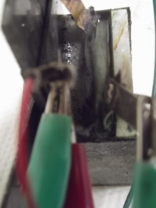 Hydrogen bubbling, esp. at higher
charge
voltages
Hydrogen bubbling, esp. at higher
charge
voltages
But it seems zinc oxide with its wide band gap is
virtually an insulator at normal charge voltages. After being a soluble
ion it returns and builds up at the electrode's surface. There it
doesn't recharge to metal and the electrolyte is increasingly blocked.
This is almost surely what has been happening to my cells all along,
and it probably explains why physical manipulation of the zinc
electrode improves it temporarily, disturbing the layer. (And I've been
blaming the copper hydroxide side.) Why, in all the reading I've done
about about zinc batteries and zinc electrodes have I never seen any
mention of this before? This is the very first time I've seen a
passivation problem mentioned. But even so, I had discounted such
problems because the SDBS should prevent the soluble ions from
migrating.
Suddenly things seem to be falling into place. With thick
electrodes the problem is worst, so it has manifest itself strongly and
before I was happy for a while with how things were going.
I think I was doing better with the manganese negative
electrode a decade ago! At least I seemed to have got that one down to
what seemed like a single main problem: continual self discharge via
hydrogen bubbling from the current collector tab. (But I only realized
what
was causing the self discharge years later.) But with no soluble ions
at all, Mn <=> Mn(OH)2 [~-1.5V @ pH 12] probably has
much lower actual amp-hours capacity than theoretical.
[25th] I tried charging the cell at 1.6 volts to shock any passive
oxide into charging. For a while it seemed to be getting better (higher
discharge voltages), but then it started getting worse again.
If I go any higher, or perhaps even at 1.6V, the positive side CuNi
current collector will start dissolving.
So... a new and modified zincode to try to solve the
problem seems to be in order. Making it thin reduces the severity and
increases cycle life. But my goal is to fix problems and get indefinite
cycle life.
The article mentioned adding 10% calcium (hydroxide) to
the zinc. The electrochemistry evidently formed a complex of more
conductive substances instead of just ZnO. That was for in alkaline
solution. I already have the SDBS to chelate the zinc ions. What else
might I try?
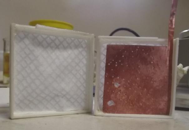 I
had made the new "telescoping" electrode box hoping to
deal with volumetric changes. Let's see... a layer of calcium oxide
painted on the current collector? And more graphite to improve
conductivity at any state of charge? Instead of 5 wt% graphite powder
in the last one, I decided to try 15-20 wt%. Being much less dense than
zinc powder, 19% looked like maybe around 40% of the volume. Would that
not put graphite between all the zinc particles and keep all the ZnO
and zinc ions connected at any state of charge? And keep the zinc from
amalgamating into large pieces?
I
had made the new "telescoping" electrode box hoping to
deal with volumetric changes. Let's see... a layer of calcium oxide
painted on the current collector? And more graphite to improve
conductivity at any state of charge? Instead of 5 wt% graphite powder
in the last one, I decided to try 15-20 wt%. Being much less dense than
zinc powder, 19% looked like maybe around 40% of the volume. Would that
not put graphite between all the zinc particles and keep all the ZnO
and zinc ions connected at any state of charge? And keep the zinc from
amalgamating into large pieces?
Perhaps those would modify the tendencies? Let's see...
that would double the volume and the zinc would only be 80% of the
weight, so it would go from 820 AH/kg to 656 AH/Kg. The volumetric
energy density is cut in half. But if it works well the utilization
should be very high. And with all that graphite, the amount by which it
shrinks and expands on charge and discharge should be considerably
reduced.
I put together the electrode and submerged it in SDBS
solution. A considerable amount of powder leaked out the "telescoping"
crack around the edges and I decided it just wouldn't do. I printed one
of the previous single sided electrode boxes. Late in the evening
(along with doing several other things) I put it together, 'glued'
around the edge with methylene chloride, then soaked it (same insides
except single sided) in SDBS again.
[26th] In the morning I tried it out.
The currents were very low,
starting to charge on the order of 20mA instead of 80 to 100+. Oops, I
forgot to put in the osmium doped cellophane sheet! Also I had used
parchment paper ironed to thin PP cloth - that was a gamble that I may
have lost. And there really wasn't enough zinc powder to compact well.
Sigh! I suppose if the next try is better I won't be sure why.
An absent minded guy like me should have a checklist. But
then I have to remember to look at it!
NEGATIVE ELECTRODE (Single sided, box type)
[...1. Obsolete already! See new checklist under [29th]. I've modified
that one too.
Pfew, did I miss anything? No wonder I do skip a non-self-enforcing
step or two at times! Now I guess there should be a sequence list for
the plus sides as well.]
POSITIVE ELECTRODE (Single sided box type)
1. 3D Print electrode box [same files as above]
2. Mix the copper hydroxide powder:
Cu(OH)2 - 94% [active ingredient... or Cu, CuOH,
CuOOH. NOT CuO - it doesn't convert to hydroxide]
Graphite powder - 5 to 7% [conductivity enhancer]
3. Cut cupro-nickel (better: monel) current collector to shape. About
26 gauge would be better than thicker sheets.
4. Pound pinholes into it with pin frog & hammer, then flatten with
hammer (IF it's thin enough to make that possible and double sided 'ode)
5. Clean it
6. Iron together thin PP cloth with the paper being used (basket coffee
filter? Watercolor paper? Parchment paper? Or?...)
7. Cut the paper and put it in the window of the box
8. Weigh it
9. Dish in enough Cu(OH)2 mix to fully fill the box (if it's in Cu(OH)2
form, it only shrinks on charge & discharge)
10. Weigh it. The difference is the amount of Cu(OH)2 mix
11. Place current collector on top then box back on that
12. Glue it all shut with methylene chloride, ABS cement and heat glue
(or just heat glue?)
13. Soak in bleach solution for 10 minutes
14. Rinse it 5 minutes
15. blot out excess water with paper towel
Performance still sucks. I guess it's that parchment
paper? [Later: No!] Ironing PP cloth to it didn't help it. Would
multiple layers of
coffee filters and PP cloth block all the powder holes and still let
electrolyte ions through freely? I redid it with a thin PP cloth with
coffee filter ironed onto both sides. Rather to my surprise that didn't
seem to help. I put a little square of 1/8" ABS in the recess of the
back of the box to put some squeeze on the zinc powder. That did help a
little. But I'm wondering if I used plasticized cellophane. They don't
tell you on the package if it is.
[27th] Running the cell over the day - mostly charging - the only thing
that seems to help improved load performance is to get a better press
on the zinc powder via the plastic spacers including the one in the
recess. That did help a bit: the discharge voltage into "10 Ω" went up
about 100mV to over 350mV/32mA instead of 250mV/20mA. Back to needing
an order of magnitude and more of current capacity improvement!
But within the disappointment there seemed to be one big
improvement: it didn't seem to be getting weaker with successive
charges. And there was much less bubbling from the electrode. The
charge current was usually only unit milliamps, but it still seemed to
be substantially less even for that current. Perhaps adding the large
percentage of graphite to the zinc has solved the passivation problem?
[28th] I noticed that where the previous cellophane I had used had
wrinkled up when I painted the dopant onto it, the new one didn't. I
made a new double faced zinc box with no cloth, just the cellophane.
This held the zinc in fine, but it worked like crap.
While knowing it wouldn't last, I put a piece of zinc foil
in between the two copper electrode boxes. After some time on charge -
which started out way over 100mA - it put out much better load currents
and voltages - almost a volt into 10 ohms. Short circuit current hit
400mA. That's still short of the desired or "ideal" 50mA/sq.cm (~1.0
amp), but at least it's in the ballpark. At this point some of the
blame for low currents probably is in the copper side. But only the
great zinc improvement made the copper weakness apparent. I had to make
a "real" zinc'trode that worked.
[29th] I put the electrode I had made by ironing the edges of the cloth
shut with the powder in it back in. Decent currents (10mA/sq.cm instead
of 1) came back, but it will doubtless "passivate" again with charging.
So I think I should go back to this format but with the graphite
enriched zinc mix, and find the other roll of cellophane that I used
before. (What was the name on that roll, again?)
PP-parchment paper fabric
envelope,
ironed shut at the edges with heavier PP cloth
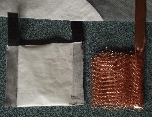 In looking for the thin white PP cloth and the cellophane, I ran across
rolls of copper "window screen" mesh I had purchased a while back. Mesh
hadn't seemed to work as well as solid copper foil, so I hadn't used
it. (But the copper mesh I had used before was coarser, heavier,
expanded mesh. In this one the squares were about 1.5mm between thin
strands.) A new plan came to me with this lightweight mesh: wrap it up
into several layers. The zinc powder and copper mesh would all be all
though the electrode and ideally no zinc particle would be even a
millimeter away from some strand of copper current collector. Even a
thick one should work great and with the graphite powder, I doubt
there'd be much ZnO surface passivation. And there would be no such
thing as a "single sided" zinc electrode.
In looking for the thin white PP cloth and the cellophane, I ran across
rolls of copper "window screen" mesh I had purchased a while back. Mesh
hadn't seemed to work as well as solid copper foil, so I hadn't used
it. (But the copper mesh I had used before was coarser, heavier,
expanded mesh. In this one the squares were about 1.5mm between thin
strands.) A new plan came to me with this lightweight mesh: wrap it up
into several layers. The zinc powder and copper mesh would all be all
though the electrode and ideally no zinc particle would be even a
millimeter away from some strand of copper current collector. Even a
thick one should work great and with the graphite powder, I doubt
there'd be much ZnO surface passivation. And there would be no such
thing as a "single sided" zinc electrode.
5 x 30 cm with a copper foil rod came to 9.3 grams. Maybe
less mesh and a thinner rod next time.
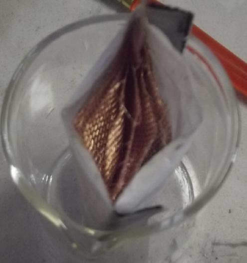 Envelope ready to stuff in 10g
zinc mix.
Envelope ready to stuff in 10g
zinc mix.
1. Mix the zinc powder:
Zn - 85-80% [active ingredient]
Graphite powder - 15-20% [conductivity enhancer]
Zircon - .5% [hydrogen overvoltage raiser]
2. Make a PP cloth & parchment paper "envelope" (see description)
2. Make copper mesh current collector with copper terminal post
3. Paint a layer of calcium hydroxide on it
4. Dope two pieces of cellophane (or one larger to fold at the bottom)
for both faces
5. Cover the outside faces of the current collector with the cellophane
(doped side in) and put it all in the box
6. Spread the mesh out to open the top of the envelope wide
7. Dish in 10 grams of zinc mix. Try to fill the envelope evenly.
(Note: metallic zinc will expand some when discharged to ZnO.)
8. Put another strip of heavy PP cloth across the top and iron it shut
9. Soak in SDBS solution for an hour
10. blot out excess water with paper towel
I put that together and got it going by early evening. I
extracted a piece of the old cellophane (crinkly) from a previous
electrode and put that on one face, and I put a new doped piece
(non-crinkly) on the other. I figure I should be able to tell whether
it works better with the copper on one side or the other, or if
the type of cellophane actually isn't an issue. I also used parchment
paper since it didn't seem to have helped to switch to coffee filter in
the last rendition. Its holes are much finer than the coffee filter
holes, but if I can see holes at all, how can it possibly block
molecular size electrolyte ions? (The only powder that came out during
handling was around the terminal. The PP wouldn't iron onto the copper,
and I didn't bother with heat glue. Also I folded the copper foil
terminal over, making an inside slot in it.)
It seemed to work okay, with one copper'trode on the
"crinkly" cellophane side. In fact, it seemed to be improving with
charging before bedtime, rather than load voltages dropping. Tomorrow
will tell more. (Dang! Somehow I turned the charge off before I went to
bed, so it did nothing all night.) Short circuit current was only 170mA.
[March 1st] After about a 2 hour charge I tried another load test. It
ran much longer before it hit .500V (38 minutes), starting off a little
higher, over .7V for a few moments. A second test after about 3 hours
of charging wasn't as good - it started just a little lower and lasted
28 minutes.
While it was recharging at 33mA, I pulled out the zinc and
turned it around so the non-crinkly side faced the copper. Charging
current dropped to 14mA. However to my surprise it still put out over
.63V with a 10 Ω load, which is probably not much different from the
other side. Perhaps 10 or 20 mV lower?
But it seems to me that there was much less hydrogen
bubbling during charge when "non-crinkly" cellophane was in use. In
addition to lower current it's probably charging with higher coulombic
efficiency, that is, an amp-hour in = .95 amp-hours charge instead of
.75 amp-hours and hydrogen many bubbles. Just a thought. Hmm... short
circuit current is just 100mA instead of 170. I put it back the other
way.
A test in the early evening seemed much stronger again. It
would always start around .7 volts when I turned the 10 Ω load on, but
the times it ran to drop to .6 volts and then .5 volts (where I would
end the test) got longer and longer. There was a place the voltage drop
would slow to 2-3mV/minute, at first somewhere below .5V, then just
above, then 5.25, then 5.4. Sometimes it would stay above .7 volts for
up to 30 seconds, but only on shorter charges. Charging currents right
after a load gradually rose from 45mA to 55 to 64 and stayed higher
longer.
But the last load started at a lower voltage and ran a
shorter time. I wasn't sure if it was deterioration or just not a long
enough charge. And then I hit another idea, made a new electrode, and
didn't run it again. (I was getting ahead of myself. I should have kept
trying it - an overnight charge and a load test would have ascertained
whether performance was continuing to improve or if some zinc
passivation had set in.)
There may be better cellophane?... or something better
than cellphane? Or... what if I just doped the PP cloth and parchment
paper on the inside before I folded up the envelope? It would use more
dopant, but there would be one less layer altogether.
I got enthused and put together this electrode. I forgot
to check the checklist until almost the end and found I had forgotten
the calcium layer on the copper. Too late! By then it was late. I put
it in the cell and on charge for the night. Charge current was very low
and I thought I might have just made another version like the
"uncrinkly" cellophane.
[March 2nd] I ran a 10 Ω load test. Voltage seemed low. I fell below
.6V in 20 seconds. But it ran for 15 minutes before dropping to .500V.
It started charging at 45mA, which is more like the better side of the
previous one. If it didn't seem to be as good in a day or two I would
put the previous one back in for further tests. In the next test it did
much better - roughly comparable to the previous electrode.
[March 3rd] A test in the morning gave similar results to the previous
day - No deterioration. It would run for 1/2 an hour or so from about
.7V until it was down to .500V. Current obviously still sucks. 50mA is
only about 2.5 mA/sq.cm. 50mA for half an hour is only about
30mA-hours, but it was by no means exhausted, only its feeble current
capacity overdriven. After this test, once it was already down to .5
volts, I switched to a 50 ohm load without recharging and it put out
.813V, 16mA for 15 minutes before beginning a very gradual descent. In
half an hour it was still at .8V. Here it started dropping by about
1mV/minute, then a bit less. I turned it off after 120 minutes at .717
volts.
But with a well charged cell all the voltages should be
nearer if not over 1.1 volts. I am really hoping to be able to multiply
the mA/sq.cm figure by 5 or more - somehow. But low current capacity by
area can be compensated by having a large interface area, ie, having
many of these electrodes all in parallel in a longer box, which at the
same time gives huge storage capacity. Two electrodes only give about
20 sq.cm, But with two-face electrodes each additional one adds another
20 sq.cm. (I'm not about to try doing rolled up electrodes.)
After a few days the initial voltage dropped more and
more.
The graphite helped, but didn't solve the problem. One more thing I can
think of to try is acetone. "To be Continued..."
Electricity
Generation
My Solar Power System
The Usual Daily/Monthly/Yearly Log of Solar
Power Generated [and grid power consumed]
(All times are in PST: clock 48 minutes ahead of local sun
time, not
PDT which
is an hour and 48 minutes ahead. (DC) battery system power output
readings are reset to zero
daily (often just for LED lights, occasionally used with other loads:
Chevy Sprint electric car, inverters in power outages or other 36V
loads), while the
grid tied readings are cumulative.)
Daily Figures
Notes: House Main
meter (6 digits) accumulates. DC meter now
accumulates until [before] it loses precision (9.999 WH => 0010
KWH), then is
reset. House East and Cabin meters (4
digits) are reset to 0 when they get near 99.99 (which goes to "100.0")
- owing to loss of second decimal precision.
Km = Nissan Leaf electric car drove distance, then car was charged.
New Order of Daily Solar Readings (Beginning May 2022):
Date House, House, House, Cabin => Total KWH Solar [Notable
power
Uses (EV); Grid power meter@time] Sky/weather
Main
DC East
(carport)
January 2024
29th 915.35, 8.51, 65.42, 47.14 => 3.48 [55Km; 12800@18:00]
30th Double OOPS! (and right at month end yet!) (prorated 1.74 as .74,
.05, .50, .45)
31st (prorated 1.73 as .73, .04, .50, .45) [50Km;
12868 (prorated)]
February
01st 918.76, 8.72, 66.84, 48.74 => 1.73 (prorated 1.73 as .73, .04,
.50,
.45) 5.20 [12873@18:30]
02d 922.59, 8.87, 68.91, 49.92 => 7.23 [12895@21:30]
03rd 925.34, 8.94, 70.90, 51.80 => 6.69 [55km; 12931@21:00; 50Km]
04th 929.18, 9.03, 73.09, 53.90 => 8.20 [12953@18:00]
05th 932.04, 9.08, 74.63, 55.32 => 5.87 [12980@17:30]
06th 932.83, 9.16, 74.96, 55.72 => 1.60 [20Km; 13002@18:00] Power
failure through heart of the day cut solar to grid way down.
07th 935.20, 9.25, 76.80, 57.18 => 5.76 [13028@17:30]
08th 936.38, 9.39, 77.39, 57.91 => 2.64 [13051@18:00]
09th 936.75, 9.49, 77.51, 58.15 => .83 [85Km; 13085@17:30]
10th 939.68, 9.62, 79.65, 59.97 => 7.02 [70Km; 13124@21:30; 50Km]
11th 944.92, 9.66, 82.45, 62.98=>11.09 [55Km; 13152@18:30] Now
that's sunshine!
12th 949.24, 9.72, 85.02, 65.46 => 9.43 [55Km; 13185@18:00]
13th 954.09, 9.80, 87.09, 67.78 => 9.32 [13208@22:30]
14th 959.74, 9.87, 89.54, 69.67=>10.06 [55Km; 13231@18:00]
15th 965.56, 9.94, 91.89, 73.28=>11.85 [13251@18:00]
16th 968.47,10.22,94.24, 75.55 => 7.81 [13270@17:30]
17th 969.78, .09, 94.85, 76.35 => 2.82 [55Km;
13309@21:30;
50Km]
18th 971.11, .16, .61, 77.11 => 2.77
[13322@17:30]
19th 976.62, .20, 3.61, 80.38=>11.82
[13344@18:00]
20th 978.90, .25, 4.75, 81.75 => 4.84 [50Km;
13395@18:30]
21st 980.00, .29, 5.19, 82.36 => 2.19 [13418@18:00]
22d 984.40, .35, 7.17, 84.64 => 8.72
[13440@19:00]
23rd 986.96, .42, 8.24, 85.87 => 4.93 [90Km;
13480@19:30]
24th 990.24, .47, 10.12, 87.52 => 6.86 [55Km; 13524@21:30;
50Km]
25th 994.99, .51, 11.91, 89.74=>10.63 [13555@19:00]
26th 1001.49, .58, 15.53, 94.12=>14.57 [13582@18:00]
27th 1004.87, .65, 16.60, 95.75 => 6.15 [60Km; 13622@18:00]
28th 1008.29, .74, 18.31, 1.72 => 6.94 [13638@18:30]
29th 1014.55, .82, 21.16, 5.52=>12.99 [13659@18:30]
March
1st 1016.13, .88, 21.68, 6.14 => 2.78
[13683@19:00]
Chart of daily KWH from solar panels.
(Compare February 2024
(left) with January 2024 & with February 2023.)
Days of
__ KWH
|
February
2024
(18 Collectors)
|
January 2024
(18 C's)
|
February 2023
(18 C's)
|
0.xx
|
1
|
14
|
|
1.xx
|
2
|
6
|
4
|
2.xx
|
4
|
3
|
6
|
3.xx
|
|
2
|
4
|
4.xx
|
2
|
2
|
1
|
5.xx
|
2
|
1
|
4
|
6.xx
|
4
|
2
|
4
|
7.xx
|
3
|
1
|
2
|
8.xx
|
2
|
|
1
|
9.xx
|
2
|
|
|
10.xx
|
2
|
|
1
|
11.xx
|
3
|
|
1
|
12.xx
|
1
|
|
|
13.xx
|
|
|
|
14.xx
|
1
|
|
|
Total KWH
for month
|
201.53
|
68.18
|
132.46
|
Km Driven
on Electricity
|
967.2
(130 KWH?)
|
1117.8
(160KWH?) |
713.1 Km
(110KWH?)
|
Things Noted - February 2024
* The abysmal power generation figures of a cloudy January, following a
cloudy November and December, when one
says "Why bother?" started looking up again in February.
* In fact this February was FAR sunnier than February 2023!
* In 2023-2024 the solar systems provided about half of all the power
used here. This was owing to some sunny weather and to using less power
overall.
Monthly Summaries for FIVE Years: Solar Generated KWH [&
Power used from
grid KWH]
Month: House system (+ DC system at house) + Cabin system = KWH made
[used from grid]
2019
March 1-31: 116.19 + ------ + 105.93 = 222.12 KWH - solar [786 KWH
used from
grid] (10 solar panels
total)
April - 1-30: 136.87 + ------ + 121.97 = 258.84 KWH [608 KWH]
May - 1-31: 156.23 + ------ + 147.47 = 303.70 KWH [543 KWH] (11th
solar panel connected on lawn on 26th)
June - 1-30: 146.63 + 15.65 + 115.26 = 277.54 KWH [374 KWH] (36V, 250W
Hot Water Heater installed on 7th)
July - 1-31: 134.06 + 19.06 + 120.86 = 273.98 KWH [342 KWH]
August 1-31:127.47 + 11.44+91.82+(8/10)*96.29 = 307.76 KWH [334 KWH]
(12th solar panel connected
on lawn Aug.
1)
Sept.- 1-30: 110.72 + 15.30 + 84.91 = 210.93 KWH [408 KWH]
(solar includes 2/10 of 96.29)
Oct. - 1-31: 55.67 + 13.03 + 51.82 = 120.52 KWH solar
[635 KWH used from grid]
Nov. - 1-30: 36.51 + 6.31 + 26.29 = 69.11
KWH solar [653 KWH used from grid]
Dec. - 1-23: 18.98 + .84* + 11.70 =
31.52
KWH, solar + wind [711 KWH + 414 (while away) = 1125 from grid]
2020
Jan. - 6-31: 17.52 + ------* + 10.61 = 28.13 KWH,
solar+ wind [1111 KWH from grid]
Feb. - 1-29: 56.83 + ------* + 35.17 = 92.00 KWH,
solar + wind [963 KWH from grid]
* The solar DC system was running the kitchen hot water
tank. Now it's only running a couple of
lights - not (usually) worth reporting. So there's just the 2 grid tie
systems:
house and "roof over travel trailer" (AKA "Cabin").
One year of solar!
March - 1-31: 111.31 + 87.05 = 198.37 KWH solar total
[934 KWH from grid]
April - 1-30: 156.09 + 115.12 = 271.21 [784 KWH
from grid]
May - 1-31: 181.97 + 131.21 = 313.18 KWH
Solar [723 KWH from grid]
June - 1-30: 164.04 + 119.81 = 283.82 KWH Solar [455 KWH
from grid]
July - 1-31: 190.13 + 110.05 = 300.18 KWH Solar [340
KWH from grid]
August- 1-31: 121.81 + 83.62 = 205.43 KWH Solar [385KWH
from Grid]
Sept. - 1-30: 110.68 + 65.09 = 175.77 KWH Solar [564
KWH used from grid]
Oct. - 1-31: 67.28 + 42.55 = 109.83
KWH Solar [1360 KWH from grid -- Renters!]
Nov. - 1-30: 35.70 + 20.79 = 56.49
KWH of Solar [1301 KWH from grid]
Dec. - 1-31: 19.78 + 11.31 = 31.09
KWH Solar [1078 KWH used from grid]
2021
Jan: 25.47 +
18.58 = 44.05
KWH Solar [1185 KWH used from grid] (1
solar panel moved to DC system only -- 11 panels)
Feb: 47.18 + 33.22 = 80.40
KWH Solar [1121 KWH used from grid]
Two years of solar!
Mar: 81.73 + 55.22 + 2.2 (DC) = 139.15 KWH
Solar
[1039 KWH grid]
April: 161.83 + 112.35 + .44(DC) = 274.62 KWH
Solar
[680 KWH from grid]
May: 156.25 + 97.22 + 1.29(DC) = 254.76
KWH
Solar [678 KWH from grid]
June: 197.84 + 112.07 + 2.21(DC) = 312.12 KWH Solar
[& 448 KWH from grid]
(Connected
12th solar panel -- 13 panels total but one goes to DC system
only.)
July: 204.35 + 121.21 + 4.06(DC) = 329.62 KWH
Solar [426 KWH from grid; 150(?) KWH used by Nissan Leaf]
Aug: 176.19 + 102.91 + 5.37(DC) = 284.47 KWH Solar [477 KWH
from grid; 165 KWH (est) used by car]
Sept: 94.35 + 51.34 + 3.30(DC) =
152.29 KWH Solar [590 KWH from grid; 155 KWH (est) used by car]
Oct: 77.52 + 41.85 +
4.10(DC) = 123.47 KWH Solar [1066 KWH from grid; 150 KWH (est) used by
car] (2 new panels on pole
making 14 --
but they are mostly in shadows all winter.)
Nov: 34.69 + 18.92 + 3.82 = 57.43
KWH Solar [1474 KWH from grid (ouch!); 140 (est) used by car]
Dec: 24.00 + 5.22 + 3.76 = 32.98 [1589 KWH from grid (ouch
again! Must be the -10°'s); 120 KWH used by car] (New switches allow switching
some panels
between AC and DC as needed, so all 15 panels are productively
employed.)
2022
Jan: 32.83 + 20.54 + 4.57 =
57.94 KWH Solar [2556 from
grid] Double ouch! Trailer 400W heater, Perry's RV 500W heater, bedroom
heat, car using extra power (100 KWH with less driving)... and so
little
sun!
Feb: 66.63 + 32.09 + 3.42(DC) = 102.14 KWH Solar [1118
KWH from grid; 130 (est) used by car]
Three years of solar!
March:128.53 + 82.29 + 3.66(DC) = 214.48 [1124 KWH from grid;
160 KWH (est) used by car]
April: 251.29 + 149.87 + 3.01(DC) = 404.17 KWH Solar
[911
KWH; est. 170 KWH used by car]
May: 255.01(house)+6.46(DC)+140.46(carport)+145.91(cabin)=547.74
KWH Solar [933 KWH from grid;
140 KWH (est) used by car; Bitcoin miner using extra power from 22nd
on.] (3 new solar panels
on carport roof
-- sunniest location around -- total 18 panels)
Jun: 234.54 + 2.10 + 160.70 + 139.18 = 536.52 KWH
[from grid: 864 KWH - dang bitcoin miner!]
July: 232.12 + 4.57 + 143.03 + 139.65 = 519.37
KWH Solar [from power grid: 710 KWH; 165 KWH (est) used by car]
Aug: 205.57 + 4.20 + 157.88 + 137.47 = 505.32 KWH Solar [from
grid: 561 KWH; 145 KWH (est) used by car]
Sept:165.52 + 3.97 + 132.24 + 104.29 = 406.02 KWH Solar [from
grid: 856 KWH; car used (est): 165 KWH]
Oct: 97.96 + 2.86 + 78.76 + 59.04 = 238.62 KWH
Solar [from grid: 1067 KWH; car used (est): 143 KWH]
Nov: 47.37 + 3.30 + 37.81 + 26.43 = 114.91 KWH solar.
[from grid: 1504 KWH; car used (est): 120 KWH]
Dec: 31.05 + 3.11 + 29.46 + 16.35 = 79.97 KWH Solar. [from grid:
1266
KWH; car used (est): 135 KWH]
2023 - (House roof, lawn + DC + Cabin + Carport, Pole) Solar
Jan KWH: 40.57 + 3.06 + 28.31 + 21.85 = 93.79 Solar [grid: 1163; car
(est): 130]
Feb KWH: 59.19 + 2.70 + 38.10 + 32.47 = 132.46 Solar [grid: 1079; car:
110]
Four years of solar!
Mar KWH: 149.49 + 2.72 + 53.85
+ 92.08 = 298.14 Solar
[grid: 981; car:
140]
Apr KWH: 176.57 + 2.71 + 121.21 + 108.34 = 408.83 [grid: 676; car: 160]
"Lawn" collectors moved to South
"Wall"
May KWH:266.04 + 2.04 + 194.13 + 180.31 = 642.52 [grid: 500; car: 175]
Jun KWH: 237.55 + 3.70 + 172.56 + 126.31 = 540.12 [grid: 464; car: 190]
July KWH:236.99 + 1.95 + 169.16 + 155.21 = 563.31 [grid: 343; car: 180]
Aug KWH:223.61 + 1.78 + 158.31 + 134.40 = 518.00 [grid: 305; car: 130]
Sep KWH:124.33 + 2.33 + 92.76 + 76.23 = 295.65 [grid:
501; car: 150]
Oct KWH: 94.26 + 2.70 + 55.01 + 56.11 =
208.08 [grid: 842; car: 170]
Nov KWH: 45.70 + 3.10 + 24.35 + 15.91
= 89.06 [grid: 760; car: 120]
Dec KWH: 28.96 + 2.43 + 15.58 + 10.96
= 57.93 [grid: 815; car: 110]
2024
Jan KWH: 31.37 + 3.14 + 16.85 + 16.82
= 68.18 [grid: 909; car: 160]
Feb KWH: 96.52 + 2.36 + 49.67 + 52.98 = 201.53
[grid: 791; car: 130]
FIVE Years of Solar!
Annual Totals
1. March 2019-Feb. 2020: 2196.15 KWH Solar [used 7927 KWH
from grid]
2. March 2020-Feb. 2021: 2069.82 KWH Solar [used 11294 KWH from grid]
(More electric heat - BR, Trailer & Perry's RV)
3. March 2021-Feb. 2022: 2063.05 KWH Solar [used 10977 KWH from grid]
(4a. March 2022-August 2022: in (the best) 6 months, about 2725 KWH
solar - more than in any previous entire year!)
4. March 2022-Feb. 2023: 3793.37 KWH Solar [used 12038 KWH from grid]
5. March 2023-Feb. 2024: 3891.35 KWH Solar [used 7914 KWH from power
grid]
Money Saved or Earned - @ 12¢ [All BC residential elec.
rate] ; @
50¢ [2018 cost of diesel fuel to BC Hydro] ; @ 1$ per KWH [actual
total
cost to BC Hydro
in 2022 according to an employee]:
1. 263.42$ ; 1097.58$ ; 2196.15$
2. 248.38$ ; 1034.91$ ; 2069.82$
3. 247.57$ ; 1031.53$ ; 2063.05$
4. 455.20$ ; 1896.69$ ; 3793.37$
5. 466.96$ ; 1945.68$ ; 3891.35$
It can be seen that the benefit to the society as a whole
on Haida Gwaii from solar power installations is much greater than the
cost savings to the individual user of electricity, thanks to the heavy
subsidization of our power
owing to the BC government policy of having the same power rate across
the entire province regardless of the cost of production. And it can be
insurance: With some
extra equipment and a battery, sufficient solar can deliver essential
power in
electrical outages however long. (Feb 28th 2023: And it's probably well
over 1$/KWH by now the way inflation of diesel fuel and other costs is
running.)
With about 4000$ worth of solar panels and maybe a couple
of thousand in related equipment (and not considering my own labor) in
terms of overall net benefit and savings of diesel fuel to BC Hydro,
the installation has already paid for itself maybe twice over. In terms
of savings on my personal electric bill it has quite a way to go. (But
solar panels continue to get cheaper and to generate incrementally
higher powers per panel.)
http://www.TurquoiseEnergy.com
Haida Gwaii, BC Canada