Turquoise Energy News
Report #200
Covering
Research & Development Activities of January 2025
(Posted February 9th 2025)
Lawnhill BC Canada - by Craig Carmichael
New: Now at craigcarmichael.substack.com
***
[Subscribe: email to CraigXC at Post dot com ; request
subscription]
Main URL: TurquoiseEnergy.com
Month In "Brief"
(Project Summaries etc.)
* New Unipolar BLDC "Electric Hubcap" motor (for Sprint Car) - Hot-wire
Foam Cutters - Faraday Cabin: Insulation, Some floor joists - "SCABA"
devices (Self Contained Arctic Breathing Apparatus) - More Practical
Magnetic Refrigeration?
In Passing
(Miscellaneous topics, editorial comments & opinionated rants)
* Scattered Thots - ESD
- Detailed
Project Reports -
Electric Transport - Electric Hubcap Motor Systems
* Unipolar Electric Hubcap Motor Construction
Other "Green" & Electric
Equipment Projects
* Hot-Wire Plastic Foam Cutters - small one - "plastic mill" - large
one &
cutting styrene foam
* "Faraday Cabin" Construction - insulating with styrene foam - Some
floor joists
Electricity Storage:
Batteries (no report on battery development)
* My 36V Power Systems: Charging the LiFePO4 Cells
* Some Thoughts on Storing Solar Energy as Heat: "Dump Loads" -- Sand
Battery Experiment for February
Electricity Generation
* My Solar Power System: - Latest
Daily/Monthly Solar
Production log et cetera - Monthly/Annual Summaries, Estimates,
Notes
Unipolar "Electric Hubcap" Axial Flux BLDC motor: Construction
Finally Started
Building on my original "Electric Hubcap" motors and their
unique designs, I've had a number ideas for this for many years now,
and have added the odd refinement to the concepts in the last few. The
unipolar idea needs to have an even number of coils for balance, at
least twelve, driven by six electrical phases, so I couldn't adapt the
nine-coil ("Hubcap") or six coil ("Caik") original motors. Of course
the housings
mostly can't be metal for electromagnetic reasons. Thinking I was
going to make molded polypropylene or PP-epoxy housings, and with the
CNC table not working for the longest time, I couldn't begin.
Then, with the CNC table finally working, at the end of
December it finally occurred to me I could make a housing out of
plywood and
to rout out the special shapes for the stator directly in the wood.
With that I
decided to drop the project of converting the old Baldor motor to 36
volts and
build the motor I've really wanted for so long.
Now I've found 1/2 inch thick "polypropylene copolimer"
(PPC) sheets: tough, dimensionally stable and good for 100°C
temperatures and beyond. I should be able to rout PPC just as
easily as plywood. I'll still make it a square case for simplicity.
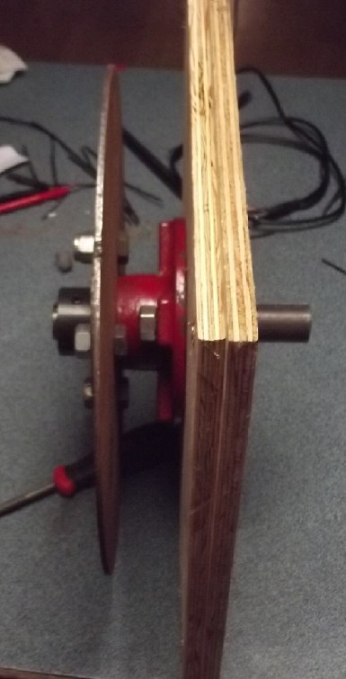
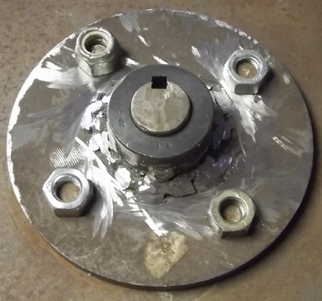 I
fitted together the rotary parts and welded a flange to a 1 inch "weld
on hub". I couldn't seem to find anyone to do my weld. My own ugly weld
should work.
I
fitted together the rotary parts and welded a flange to a 1 inch "weld
on hub". I couldn't seem to find anyone to do my weld. My own ugly weld
should work.
After working out all the
trigonometry etc. and creating a G-code file to run the course, I
routed a test copy of the desired
magnet placement jig from thin plywood - the first thing I've actually
routed on this CNC router. I didn't have a big enough piece of slippery
UHMW-PE that epoxy wouldn't stick to, so I got a piece of also
non-sticky HDPE instead. But it would seem HDPE routs differently from
UHMW: the "sawdust" stuck in the kerf and melted it right back
together. So I contrived to mount my DeWalt router (which has a speed
control) in the CNC table carriage by cutting off edges of its flange
and drilling new mounting holes. But even its lowest speed was too fast
to rout HDPE - same result.
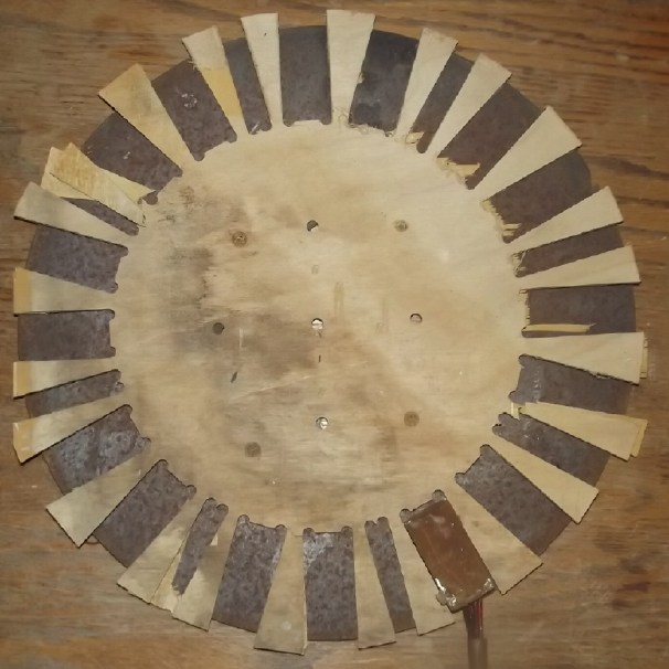
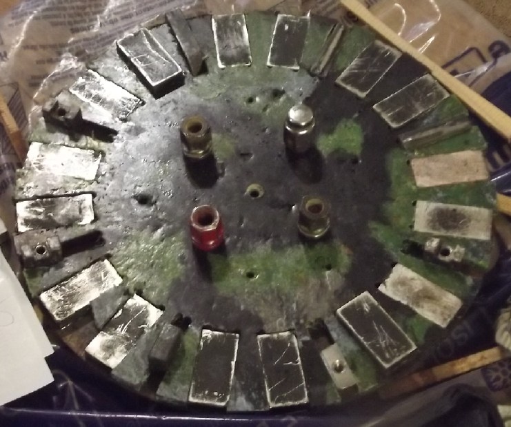
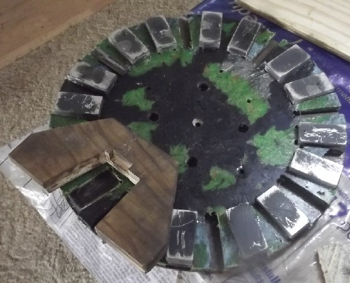 So finally I made a jig to place magnets on the rotor from a slab of PP
I had melted from ropes off the beaches. (It's still on the rotor
awaiting more magnets. I may have trouble getting it off.)
So finally I made a jig to place magnets on the rotor from a slab of PP
I had melted from ropes off the beaches. (It's still on the rotor
awaiting more magnets. I may have trouble getting it off.)
I decided to double stack the 3/8 inch thick magnets to
3/4 inch
tall and then ordered some 50 x 20 x 10 mm magnets as matching
"sideways"
magnets for the hallbach configuration rotor. On the original "Electric
Hubcap" motors there were 12 supermagnets. Here that becomes 40: two
layers of 16 'regular' plus 8 sideways magnets. All configured as eight
Hallbach alternating poles. If the original
supermagnet rotors had huge magnetic fields, this one will be
MONSTEROUS. The motor should be super efficient and have Huge torque.
And with improvements to the magnet bonding onto the rotor by roughing
all surfaces up first, I anticipate perhaps 3500 RPM should be safe
instead of just 2000, despite it being almost 13 inches diameter
instead
of 10 inches.
I put the rotor away pending the other magnets arriving.
 Then I added
to the G-code file for making the stator inner side, adding a lot
of ventilation holes. I also did holes so I could put the wire ends
through the plate to do the coil wiring on the outside where there's
lots of room. (These files take considerable time to do and then to
adjust.)
Then I added
to the G-code file for making the stator inner side, adding a lot
of ventilation holes. I also did holes so I could put the wire ends
through the plate to do the coil wiring on the outside where there's
lots of room. (These files take considerable time to do and then to
adjust.)
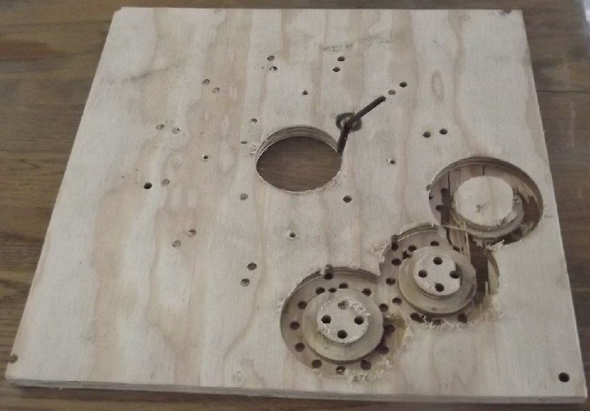
After a couple of false starts and then adjustments to the
CNC machine
configuration, I tried to test rout a test sample from 12mm plywood. It
drilled a bunch of holes fine,
but the routed coil contours cut too deep. Where the plywood curled up
just
slightly on one side, the bit went right through. I stopped it.
 But it gave me a sample to
see how the coils would fit.
But it gave me a sample to
see how the coils would fit.
I describe the
planned/expected
characteristics of the motor in the detailed
report.
Hot-wire Foam Cutters
Having filled a few wall stud spaces with foam rubber and
then polyethylene foam, I asked myself why I would want to work with
ucky fiberglass? I would happily do the rest of the structure with
these
friendlier materials.
Fiberglass wool batts: R 3.5 (per inch - R 12 in 2 by 4 wall cavities.)
Foam rubber: R ?
Polyethylene Foam: R 3
Beady Styrofoam: R 4
Extruded polystyrene: R 5
I figure even the polyethylene foam is probably better
than
fiberglass because it stops the air movement better. I could be wrong,
but 3 inches thick plus "R 1" for a 1/2 inch air gap should be at least
R 10. 3 inches of beady styrofoam would be R 13 and extruded would be R
16.
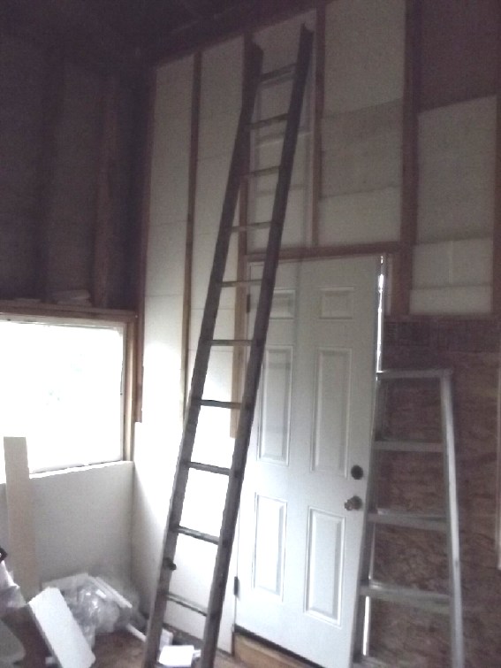 I
put an ad in Haida Gwaii Trader that I was looking for foam for
insulation. But it was all taking too long - hours for a 12 foot tall
wall space with three layers of one inch expanded styrene foan. The
worst was slicing through the material with a knife. The first person
who responded to my ad had saved some styrene packaging foam. She said
she had been planning to make a hot wire cutter for it but had never
got around to it. That gave me the idea.
I
put an ad in Haida Gwaii Trader that I was looking for foam for
insulation. But it was all taking too long - hours for a 12 foot tall
wall space with three layers of one inch expanded styrene foan. The
worst was slicing through the material with a knife. The first person
who responded to my ad had saved some styrene packaging foam. She said
she had been planning to make a hot wire cutter for it but had never
got around to it. That gave me the idea.
[January 1st] I had some ni-chrome
resistance wire that I got on AliExpress a few years ago to make
plastic recycling heaters, before I got the idea just to melt plastics
in an oven. I cut a foot long piece of the wire and connected it with
alligator clips to a power supply. It got really hot. I turned the
power down to 5 volts and, holding the alligator clips and a piece of
plastic (did I have three hands?) I pushed it in. Wow! It went like the
proverbial "hot knife through butter!" I pulled back and it came out
another way, cutting out a triangular piece.
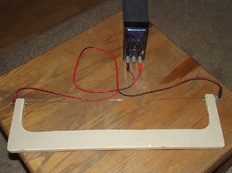 Then I made a
"bow saw" piece of plywood and put bolts through the ends. I cut a
longer wire to fit and attached it. I put in a couple of cable staples
to hold the alligator clip leeds better. Then I took it with the power
supply out to the cabin and cut a piece of foam.
Then I made a
"bow saw" piece of plywood and put bolts through the ends. I cut a
longer wire to fit and attached it. I put in a couple of cable staples
to hold the alligator clip leeds better. Then I took it with the power
supply out to the cabin and cut a piece of foam.
A project started and completed in an hour!
The setting was 14 volts, where it drew about 2-1/2 amps.
That's just 35 watts. (3 to 3-1/2 amps or more is faster. At 3-3/4 the
wire starts to glow dimly.)
 I found the
best way to cut was to lay the saw's wire on the line to be cut
(placing the cut just over the edge of a work table), hold the handle
balanced above, then turn the power On. The weight of the saw alone
pushed it through. The one inch thick pieces took about six seconds,
then power off again.
I found the
best way to cut was to lay the saw's wire on the line to be cut
(placing the cut just over the edge of a work table), hold the handle
balanced above, then turn the power On. The weight of the saw alone
pushed it through. The one inch thick pieces took about six seconds,
then power off again.
This way there was minimal smell from the plastic and it
cut fast.
I did the second of the two tall wall cavities in maybe an
hour and a half. Yes, it's still more labor intensive than fiberglass.
One layer of foam 2+ to 3 inches thick would be a lot
easier than three layers of 1 inch.
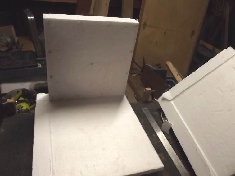
I tried
cutting a side off a cooler box by hand. It was pretty wavey.
 I
was trying to figure out how to make a jig to cut the sides off
straight. I came up with one plan, then I realized that box sides would
hit the
handle.
I
was trying to figure out how to make a jig to cut the sides off
straight. I came up with one plan, then I realized that box sides would
hit the
handle.
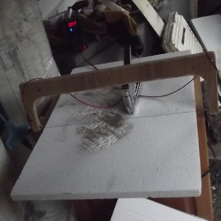
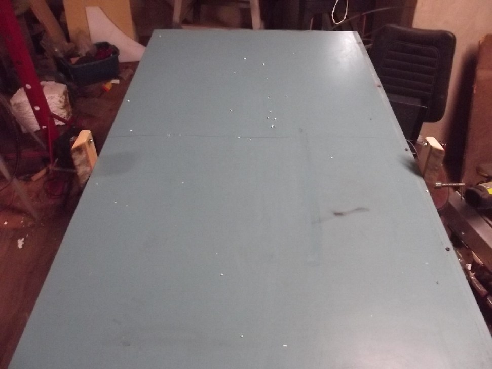
In the evening I realized I could simply C-clamp the saw
upside down to the side of a workbench.
This worked quite well. I set the plastic right in front
of the "blade", turned on the power, pushed, and melted through the
wall
thickness (15 seconds?) then drew the piece back and shut off the
power. I had to shut off the power between cuts because the wire sagged
when it was hot. It sprung back up as it cooled.
(The image perhaps isn't very clear. The C-clamped left end 'post' of
the 'saw' is at the very left; the right end is behind the end of the
steel ruler. The 'invisible' wire between is cutting the last side off
a cooler.)
By the time I
retired for the night I had cut two cooler boxes into 12 fairly flat
pieces. All this still on the same day I made the 'saw' - January
first, my 70th birthday.
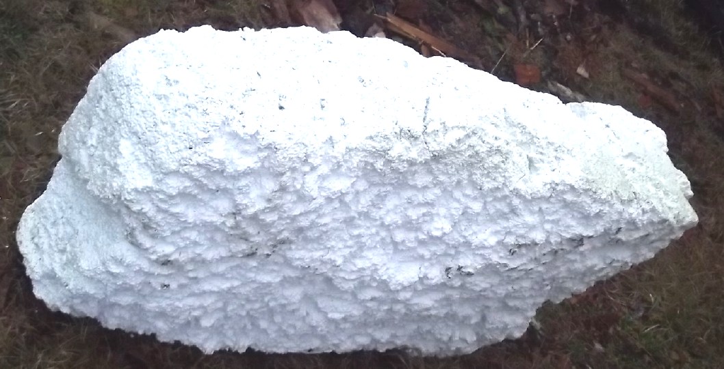
Someone told me there was a big,
ugly chink of
float foam at a nearby beach.
 I had scrounged
a 30 inch wide piece of countertop a while back. I now employed it: I
set it on a work table and turned it into a hot-wire 'table saw/mill'.
I had scrounged
a 30 inch wide piece of countertop a while back. I now employed it: I
set it on a work table and turned it into a hot-wire 'table saw/mill'.
The wooden arms are C-clamped on the sides and the wire is strung
between them at the desired height/thickness.
One turns on the power and pushes the block of foam through, along the
smooth surface, however fast it wants to go.
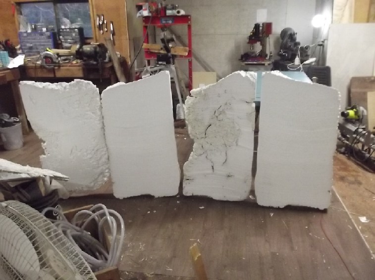
In 10 or 15 minutes: Presto! Four smooth slabs from the big chunk.
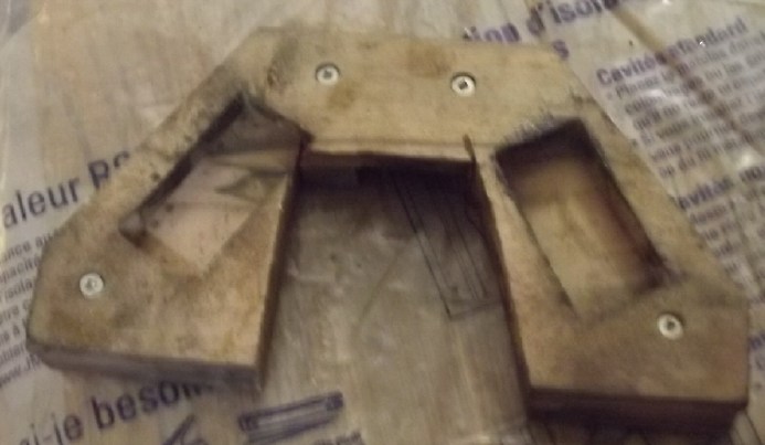
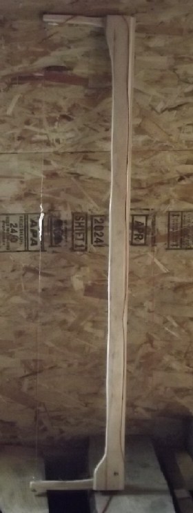 [15th] I made
a third foam cutting hot-wire saw, for cutting long edges. This one was
essentially a five foot
long copy of the first, with the refinements of having its own wiring:
a 12 foot cord and 36 volt DC plug -- and a switch.
[15th] I made
a third foam cutting hot-wire saw, for cutting long edges. This one was
essentially a five foot
long copy of the first, with the refinements of having its own wiring:
a 12 foot cord and 36 volt DC plug -- and a switch.
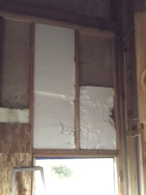 Wide (20") spaces above a window done with the float foam, edges cut
with the long saw. The missing fourth
(& best) piece was in the car to show to people.
Wide (20") spaces above a window done with the float foam, edges cut
with the long saw. The missing fourth
(& best) piece was in the car to show to people.
Faraday Cabin Construction
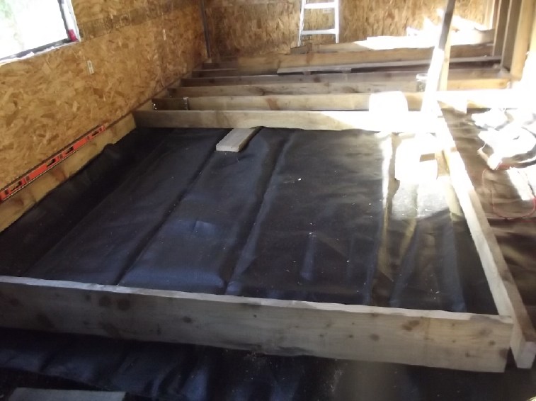 Of course, all the above foam cutting and fitting is part of the cabin
construction. But it deserved its own title. Aside from that, I put in
some of the floor joists in the southwest quarter.
Of course, all the above foam cutting and fitting is part of the cabin
construction. But it deserved its own title. Aside from that, I put in
some of the floor joists in the southwest quarter.
An Approved Solar Collector System
I gave up waiting for the solar contractor to return to
the island and return my messages. Tho the web site was still up, I
wasn't even sure she still did it any more. After a less than thorough
web
search I inquired from "Solacity.com" in Ontario about getting a "7 KW
Solar Kit" -- twenty 350 watt solar panels with ten dual microinverter
grid ties, and all rail mountings & clamps, boxes and bits &
pieces. I went with a Canadian company offering a whole "kit" because I
didn't want to be missing needed parts if I ordered them individually,
or find some of the items couldn't get Canadian electrical code
approval. All being arranged, on the 31st I finally bit the bullet and
payed the 11,000 $ for the kit, on line with a credit card. Naturally
I'll be taking advantage of BC Hydro's 75% subsidy offered for new
rooftop solar installations where the local power grid is fed with
diesel generators.
Bandstra said they would handle the entire shipping from
Ontario to my place on Haida Gwaii. I dread to find out the cost. (Even
worse than I feared: 4500$!)
Gardening
(no report. Things are still growing under the LED lights inside and
I've had a couple of tiny cabbage and cauliflowers from the greenhouse.)
"SCABA" devices (Self Contained Arctic Breathing Apparatus)
I decided the "SCABA" (Self Contained Arctic Breathing
Apparatus) Looked like a nice piece of low-hanging fruit, and if I put
it off until summer I couldn't even test it. I cut twentytwo 8x8 inch
pieces of old coroplast and washed them.
I put them together and drilled holes for two bolts to
hold them together. There things got messier. After trying to fit some
rigid plastic cut from an old motor oil container, I taped pieces of
plastic bag onto the edges. But it wasn't much of a plan: breathe in
one hole and out the other by mouth. Evidently the corner between
'inhale' and 'exhale' needs to be really well sealed, because I could
feel my warm breath coming out both the 'in' and the 'out' edges. I
stopped.
 In the meantime, while I worked it finally occurred to me to check on
line and see if such a thing already existed. There were some "heat
exchange masks" available and they had their enthusiasts. One said he
could actually wear lighter clothing in extreme cold because of the
body heat saved. But there was nothing that would hold a lungful of air
or separate the exhaled air from the inhaled as in real heat exchange
devices.
In the meantime, while I worked it finally occurred to me to check on
line and see if such a thing already existed. There were some "heat
exchange masks" available and they had their enthusiasts. One said he
could actually wear lighter clothing in extreme cold because of the
body heat saved. But there was nothing that would hold a lungful of air
or separate the exhaled air from the inhaled as in real heat exchange
devices.
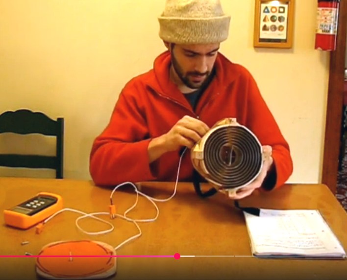
Then I looked on Youtube and found a video from 2015 of a
young inventor who had done something very similar to my idea. Rather
than corolite he had wound a long strip of alume to form two adjacent
spiral air passages for 'in' and 'out'. And he had used an actual mask
(a gas mask) to fit to his face and put two one-way flaps in it for
'inhale' and 'exhale'.
My main concern about this construction is that
condensation could build up in the bottoms of the loops, freeze, and
block the 'out' air passage. In my design, the 'out' air goes down at
45 degrees with no twists or bends and can drip out the end. Still,
ideally one would want to try both designs and see if one actually
works better in practice in cold air. Small holes if needed could let
condensation drip out -- or even back into the inhaled air to moisten
it.
Cold Weather Mask Heat Exchanger (1st working prototype)
https://www.youtube.com/watch?v=hFA5sEzijH4
Inhale Exhale Heat Exchanger Test Results
https://www.youtube.com/watch?v=k1Q8WKGKDTg
He talked about how a finished product would be more
compact and better than his working prototype. Here I have finally
found an inventor who is a worse promoter of his designs than I am.
(Was I as inarticulate as that when I was his age? Maybe!)
So his design has (AFAIK) languished for a decade. Again I
suggest that there should be a government "Department of Progress" that
among other things can connect inventors of products with entrepreneurs
or businesses looking for something worth selling, while (unlike with
the present worthless patent system) giving the inventor something
worthwhile for his invention so that he has the financial freedom to
live and continue inventing. (Each invention is unique and so is each
inventor, so "contracts", "patents" or "agreements" would probably have
to be custom deals in each case but would be enforced by the
government, who would collect the royalties from every company making
use of the invention. Doubtless some "precedents" or other guidelines
would soon be established.)
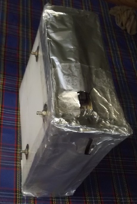 [16-18th] I
finally looked at my own corolite stack again. The layers seemed a bit
spread open on the "inner" corner so I put through another bolt. Not
seeing an easy way to incorporate a mask with valves for what was only
going to be a simple test, I used some modeling clay, alume foil and
packaging tape, and just made two holes, one to breathe in and one for
out. So I had to shift it back and forth to use it and breathe through
my mouth.
[16-18th] I
finally looked at my own corolite stack again. The layers seemed a bit
spread open on the "inner" corner so I put through another bolt. Not
seeing an easy way to incorporate a mask with valves for what was only
going to be a simple test, I used some modeling clay, alume foil and
packaging tape, and just made two holes, one to breathe in and one for
out. So I had to shift it back and forth to use it and breathe through
my mouth.
Trying it outside in cold weather, once I had exhaled
through the "out" hole a few times, with my mouth and with my tongue, I
could feel the difference in incoming air temperature between the "in"
hole and just outdoor air. That's about the best that can be said. But
the general idea was demonstrated.
I could also feel that some warm air was coming out the
"in" side as I exhaled, and so surely cold air was coming in the "out"
side keeping it from being warmer. I figure only the top 1/4 of the
unit nearest my mouth was really working very well. Bigger manifolds
and better seals all around would surely have helped a lot.
But I'm leaning toward the spiral alume idea. Thin alume
has the best heat transfer and the spiral a large surface area. If I
was going to pursue it further, which I'm not.
Bulky as they will need to be to hold a lungful or two of
air going each direction, they might hang at the chest with a strap
from the neck. I'm sure there's a good fortune to be made producing
such units for the clothing stores in really cold climate places.
Someone will do it someday.
More Practical Magnetic Refrigeration?
I ran across a magnetic refrigeration system system that
looked more practical than others with helium gas designs, and
doubtless more practical than my 2016 design where the magnet would
pick up
a gadolinium wafer as it passed, then it would fall back, tossing it
back and forth between two
heatsinks. (TENews somethingorother)
This one ran flowing water through
gadolinium alloy particles in multiple chambers inside a rotating drum
containing
magnets. Each chamber had two
inlets and two outlets, with valves. When the magnet was passing and
heating the
gadolinium, the warmed water flowed toward the heat radiator. After the
magnet had passed and the alloy became cooled, the other pair of pipes
fed
the water toward the refrigerated section. If the exact configuration
of the water flow was shown, I didn't see it. It would make sense
that the chambers were thermally in series so that cooled water from
the first was further cooled in the second and so on. (The water would
doubtless be a closed loop and deoxygenated so as to not corrode the
rare earth metals it flowed through.)
Such a unit might be no more efficient than a compressor
based refrigerator, but it should be quieter. The modest effort
described only cooled a few bottles of wine. The video:
Domestic wine cooler operated by a magnetic refrigeration system
developed by Polo - UFSC
https://www.youtube.com/watch?v=wMUPdGRA9ck
But my bet is still on someone coming up with more
efficient Peltier modules for practical and reasonably efficient solid
state refrigeration. Quietest. That would make everything else obsolete
for kitchen fridges. ...still waiting.
In
Passing
(Miscellaneous topics, editorial comments & opinionated rants)
Scattered
Thots
* I talked with one Craig at the recycling centre in DG. He said that
he used to have tinnitus, but that it was gone now. He also said he had
moved from a house to a boat at the wharf. There is electricity at the
wharf, but of course no high voltage lines (14,400V) nearby, and the
120V is run in conduct pipes ending in metal boxes - shielded - so any
electric power EMF field down on the boats would be miniscule. He uses
a diesel heater and batteries. He recharges the batteries at work, so
he probably has no AC power on his boat at all.
Strike up one more circumstantial evidence report that
everlasting tinnitus is caused by 60 Hz AC power EMF fields, but takes
a long time - days - to fade!
* Some people are excited about the idea of people going to and living
on
Mars. Personally I think that if people could actually get there
without
suffering from serious radiation sickness from "cosmic rays" long
before even arriving, the experience of being there would quickly
dampen enthusiasm. Within a day, a week, a month or a year - maybe even
a few
hours - most people would be saying "There's no place like home!" and
booking a return flight.
Robot spacecraft are exploring the solar system better
than manned missions possibly could and such projects will increase and
improve. And perhaps with the "Dragonfly" drone to Titan and the ESA
probe to orbit
Ganymede space scientists will notice that these worlds already
glimpsed by probes are both covered with life. (...And then kick
themselves for having completely glossed over all the unexpected and
fascinating evidence and images and not being curious enough to
decipher them!)
Then someday we will be able to make and control the
powerful magnetic fields needed to deflect the "cosmic rays" health
hazard as well
as to navigate through space. Who knows, that may yet be within my
lifetime. No one had ever launched a satellite into Earth orbit when I
was born and a trip to Pluto was expected to take 100 years. The
transistor had recently been invented and the stupendous strides in
electronics have given us the internet and world-wide connectivity
between individuals. I certainly never thought I would see such things
happen.
Then we will visit. Maybe even just one time, like the
Apollo moon project. Aside from the stupendous excitement of new
discovery and the feat of getting there, there's probably no sufficient
real reason to stay. If there is, it's probably just the excitement of
exploration, scientific research, or for a small team of people try to
find and mine
exceptionally rare minerals. (Who wouldn't want a kilogram of osmium or
iridium? I already have a kilogram of dysprosium. Completely useless to
me. oops.)
ESD
(Eccentric Silliness Department)
* Remember when scuba was
S.C.U.B.A., laser was L.A.S.E.R. and NASA was N.A.S.A.? Then sometime
(1960's IIRC) everybody finally got fed up with putting the dots on the
ever
growing number of abbreviation-words and quite suddenly they became
"acronyms". Then some of them weren't even capitalized any more and
people have forgotten what the letters stand for.
* A.M.: "ante meridian" The time before the sun reaches its zenith.
Somehow this has become "the time before the government tells you it's
12 o'clock" - even if it's 2 hours before actual noon.
* Everybody always overexaggerates everything way, way too much.
"in depth reports"
for each project are below. I hope they may be useful to anyone who
wants to get into a similar project, to glean ideas for how something
might be done, as well as things that might have been tried, or just
thought of and not tried... and even of how not to do something - why
it didn't work or proved impractical. Sometimes they set out inventive
thoughts almost as they occur - and are the actual organization and
elaboration in writing of those thoughts. They are thus partly a diary
and are not extensively proof-read for literary perfection,
consistency, completeness and elimination of duplications before
publication. I hope they may add to the body of wisdom for other
researchers and developers to help them find more productive paths and
avoid potential pitfalls and dead ends.
Electric
Transport
Finally:
Unipolar
"Electric Hubcap" Motor Construction !
Resuming Long Delayed Project
Having thought of making & routing a prototype motor body out of
wood, instead of molding it from PP or PP-epoxy, the big bottleneck to
constructing my long planned unipolar motor was
bypassed.
That seemed like a great reason to abandon rewiring the
old, traditional "clunky" design Baldor induction motor to 36 volts
before going any farther. It's not just the motor: either motor will
have to have a new motor controller wired in and will have to be
mounted into the car and connected to the wheel with a planetary
reducer. All this work would have to be redone in order to change to a
different type of motor with quite different dimensions. Of course, I
could put the new motor in the Toyota Echo instead and turn it into a
hybrid. But either way I might never get to the second project.
So now that it looks doable I would much rather work on
the "ultra efficient" axial flux, BLDC motor design Instead rather than
in addition, later. There's been far too much "for later" on this motor!
Now it seems there's no physical difference between this
as a regular
BLDC motor and my planned unipolar BLDC motor. It's just in how the
coils are wired, which is fairly easy to change. So I still have two
options: make the unipolar motor with the special controller for it, or
if that gets to be too much or isn't working out well, buy a typical
500 amp, 36 volt BLDC motor controller (Kelly controller?) and rewire
it for that. (If this motor can hit about 20 peak horsepower at 3500
RPM, that's a little over 400 amps at 36 volts.)
Later I found Polypropylene-Copolymer (PPC) in 1/2" thick
sheet. I could rout it the same way as wood and it's an even better
choice
of material for the housing than PP.
Motor Features
* Robust automotive 'trailer wheel' rotating parts with robust, low
friction cup & cone bearings on one inch 4140 HTSR steel shaft. 4
inch,
four stud bolt pattern on both rotor and stator. "Wheel hub" with cup
& cone bearings (center of
stator) is turned in a lathe to a shorter than usual length as required
to fit. Any length axle shaft may be employed as required.
* Polypropylene-copolymer (PPC) housing is strong, tough, dimensionally
stable and relatively high temperature (100°C, 150° peak). It will be
made from
flat 1/2" sheet PPC material as a 15 x 15 x 5.5" cube, cut and CNC
router
milled shapes as required. (A metal casing,
except on the face behind the rotor, would create electromagnetic
interference with the rotor magnets, causing heat and inefficiency.)
* A 12.68" (322mm) rotor and stator magnetic outer diameter to provide
huge torque. The
large diameter also distances the rotating magnets sufficiently from
the steel center assembly.
* 12 stator coils with 2" O.D. x 1" tall iron powder toroidal cores and
27
turns of #11 AWG magnet wire. The wire will be epoxied to the cores
with
ilmenite impregnated epoxy, with extra coats to thicken the ilmenite on
the outside. The ilmenite (iron-titanium oxide mineral, ferromagnetic
plus paramagnetic)
completes the magnetic path so each coil is an
independent unit. In most motors all the coils have to mount on a
common
metal backing with magnetic paths going between coils. This inevitably
ends up as a less-efficient complete
assembly of all coils including the backing, made of die cut laminated
iron, for
which costly custom punches and dies are required. I first tried rutile
(titanium oxide paramagnetic mineral, TE News #36), which helped, but
ilmenite proved even more effective. (TE News #38,46,54.)
* 8 powerful magnet poles (40 magnets!) in Hallbach configuration. With
some 'sideways' magnets for Hallbach, most of the flux comes out on the
"business" face of the rotor facing the stator coils. Owing to the
little flux coming out the back, the rotor is a 1/8 inch steel plate
instead of 1/4 inch or thicker, making it lighter. Main magnets are 2 x
1 x 3/4 inches (here as a stack of two @ 3/8 inch). Hallbach magnets
are 50 x 20 x 10 mm, set on edge between rotor magnet poles. (20mm is
just over 3/4 inch.) All magnets are high strength, N48 or N52. With
roughened surfaces and a pool of the best epoxy on the rotor going half
way up the magnets, high RPM's should be safely attainable.
* The flux gap between rotor and stator is about 1/2 an inch, as is
common in axial flux motors. This allows a protective PPC plate between
them making separate rotor and stator compartments.
* A Hall Effect magnetic sensor assembly detects rotor magnet positions
for the
unipolar motor controller.
* A centrifugal fan spins behind and with the rotor, drawing air though
openings
in the rotor end housing and blowing it across the motor. Holes around
the
coils in
the other face force the cooling air to exit past the coil wires and
through the core centers for best cooling.
* Unipolar operation runs each coil in only one direction: north OR
south. Iron remagnetization (hysteresis) losses are avoided and the
controller is
theoreticly less prone to destructive "shoot-though" currents. 1/3
of the coils are energized at a time instead of 2/3, with a modified
rotational sequence. There are six phases instead of three, each phase
powering opposite-side pairs of coils for balanced magnetic attraction
between rotor and stator. (This is the reason there need to be 12 coils
rather than the nine or six of my previous motors. Other than that I
want it to power a car anyway.)
* Some expected ratings are 3500 RPM max., 15 KW (20 HP) peak (= 414
amps
at 36 volts), peak efficiency over 95%, full load efficiency 75%,
torque 50-60 foot-pounds.
Design Considerations
 The rotating assembly was previously done in steel with
trailer wheel type parts, and the magnet rotor plate was cut and bolt
holes drilled. The case and
assembly
would attach that at the coils end with the four bolts to the
cut-down "trailer wheel" hub.
The rotating assembly was previously done in steel with
trailer wheel type parts, and the magnet rotor plate was cut and bolt
holes drilled. The case and
assembly
would attach that at the coils end with the four bolts to the
cut-down "trailer wheel" hub.
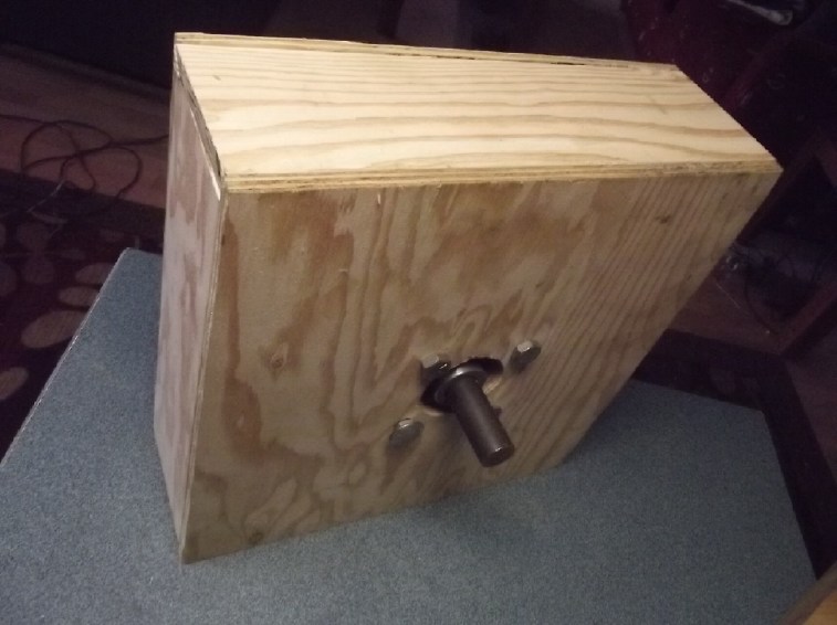
It seems to me that while the motor spins in a circle, the
case could be a square box. That should make making and mounting it
simpler, and metal bolts and pieces could attach in the corners,
farther away from the spinning magnets to create the minimum of
electromagnetic drag. Plywood PPC should make for best
excellent dimensional
stability.
The stator end that attaches the rotor assembly needs to
be very stiff, so I think two pieces of plywood epoxied together for
that, maybe 1/2 inch plywood making an inch. (or is it 12mm making 24mm
these days? Measure and size accordingly!) Then, the four outer sides
and the rotor end simply form an enclosure, screwed or bolted to the
one inch "main plate". They too can be 1/2 inch plywood. The end of the
box will have holes toward the center to allow air in, as there will be
a fan blades rotor right behind the magnet rotor to drive a powerful
air flow around the rotor through to the coils end, where the air will
exit near the wires and cores. (While the end behind the magnet rotor
is the one piece that could be a steel plate, there is no point because
with no attachment except to the sides, it takes no stresses and won't
even get warm. Sheet metal would probably vibrate and make noise.)
346mm should be large enough for the inside of the square
box, so (w. 12mm plywood), 370mm (14.6 inches) outside dimensions. I
don't want to make it any bigger than necessary as it'll be hard to fit
that large a diameter under the hood. And the larger it is, the more
the angle on the CV shaft joint while driving straight.
Only one piece of the end plywood, and an inside plate (3/8 inch?) for
the inside ends of the coils need to be fitted out on the CNC router
table with "mounting pads" for the toroidal cores and air spaces around
the coil wires.
I decided I would have to use the iron powder toroidal
cores despite their 70°C max rating and similar rating for the epoxy to
"glue" the coil wires on. One change from my previous motors will be to
mix the ilmenite into the epoxy so all the wires will be coated in
between and direct to the core piece as well as an extra coat/layer or
two around the outsides. Hopefully that will further improve magnetic
performance as well as make sure none of the ilmenite coating flakes
off as has been the case with mixing "liquid rubber" and ilmenite for
my previous coils.
[12th] I checked over and adjusted the gcode file to route out the
magnet holder jig/template. (I wrote it a couple of years ago when the
rotor disk was cut, by CNC plasma.) I found a sufficient piece of HDPE
to
make it from - a plastic breadboard I bought a decade ago for just such
a purpose. (What a junk collector I am. Sometimes it pays.)
Motor Plywood Body Assembly
[13th] I bought a piece of 12mm plywood to cut the motor body parts
from, and I cut the outer end plate, 370mm square. I got the
inspiration to "skin" the unit with epoxied PP cloth. I still might
paint that with high temperature paint on the stator inside surfaces.
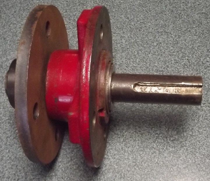 In fooling around fitting things I had been using trailer
stub axles, but now I realized that the best combination would simply
be a length of one inch round machine shaft (4140 HTSR steel) with a
cut-down trailer wheel hub, and a "wheel bolts pattern" four inch
flange
welded to a one inch I.D. "weld on hub". Too simple! (except for the
welding. ug.) The only thing the stub axle had going for it was that
the flange was already welded to it. Other than that it was heavier,
only so long, and
would be harder to turn the end to 24mm on a lathe.
In fooling around fitting things I had been using trailer
stub axles, but now I realized that the best combination would simply
be a length of one inch round machine shaft (4140 HTSR steel) with a
cut-down trailer wheel hub, and a "wheel bolts pattern" four inch
flange
welded to a one inch I.D. "weld on hub". Too simple! (except for the
welding. ug.) The only thing the stub axle had going for it was that
the flange was already welded to it. Other than that it was heavier,
only so long, and
would be harder to turn the end to 24mm on a lathe.
 [14th] I cut the inner
piece of plywood; the one that will need to have
the CNC routing to make "pads" for the toroid coils, including the bolt
and center holes, and screwed the two pieces together. (epoxy together
later.) I figured out a fit that worked with the existing parts, adding
a shaft collar (found - Yay! - with a search to the very back of an odd
drawer) and some spacer washers on the shaft. The
stator's "trailer wheel hub" wasn't ideal, with the two bearings being
needlessly close together, but since the motor is to drive a planetary
gear and there'll be no forces pushing to one side, it should be fine.
The fan
will be made from a separate circle of sheet metal with the fins bent
out from it, behind and flush against the magnet rotor.
[14th] I cut the inner
piece of plywood; the one that will need to have
the CNC routing to make "pads" for the toroid coils, including the bolt
and center holes, and screwed the two pieces together. (epoxy together
later.) I figured out a fit that worked with the existing parts, adding
a shaft collar (found - Yay! - with a search to the very back of an odd
drawer) and some spacer washers on the shaft. The
stator's "trailer wheel hub" wasn't ideal, with the two bearings being
needlessly close together, but since the motor is to drive a planetary
gear and there'll be no forces pushing to one side, it should be fine.
The fan
will be made from a separate circle of sheet metal with the fins bent
out from it, behind and flush against the magnet rotor.
Later I cut the sides and back end - the magnet rotor end.
Even in these small sizes the plywood was visibly warped. Ug.
Rotor to "Weld-On Hub" Welding
[16th] To weld
the one inch hub to the "wheel" rotor plate, I was going
to ask someone who would know if he knew any good welders, but he
didn't come to the cafe that day. I went across the street to the
garage but no one was around. (No one around and doors wide open. Who
would dare do that in most places these days?) So I went home and
welded it myself. (No one has seen such ugly welding as mine! But I got
lots of steel on it. It won't break.)
It seems I didn't get it quite straight. But with a very
thin shim under one side it ran straight. It also wobbled in and out,
which turned out to be play in the bolt holes. I'll have to figure
something out for that.
The next day I ran across a hacked-up "disk brake rotor"
with a one inch hub center in my junk. I would only have had to drill
the four
holes in it (without play!) for the bolts. It would have been perfectly
straight, and lighter. There's often more options than one suspects.
Gcode Program to Route Stator
[15th] I started on the file for the routing of the plywood stator
plate, using a sreadsheet to work out all the sines and cosines for a
twelve coil circle. I included many 6mm ventilation holes, inside the
iron powder toroid core centers, under the coil wires outside of the
core and a few more between coils and toward the center of the motor.
(6mm is the size of the router bit as well as being a bit too small to
stick a pencil into.)
As I spent a couple of hours on a number of laborious
trigonomic calculations and their conversion into G-code I couldn't
help but think there's CAD programs to generate .gcode files more
easily. Oh well, there's a learning curve to those too, and I make new
motor
designs rather rarely. There's one such program I never got very
familiar with and I forget how to use it between designs, so the
learning curve - and the install on another computer - seems to be
"each time" instead of "once". And once I had the design, last time I
couldn't find a program to convert its .dxf file to .gcode. So forget
it! I'll still need to route it onto a scrap piece and probably make
adjustments until I like the result.
[16th] Continued. I got as far as test running the gcode program on the
router and being pretty happy with the result. I thought it would need
more ventilation holes. I ended up with 16 at each coil position, four
in the donut center and 12 around the outside under the wires. That's
192 holes, in the best places to cool the coils. Enough?
Making Magnet Placement Jig
 [19th] I did
some final adjustments to the magnet rotor gcode and did a
dry run, with the router above the table and turned off. It seemed to
me it was all somewhat too small. I found in the router configuration
the default "200" for the "turns-per-inch" of all axes. Hadn't I
adjusted that, again around two years ago? I remember laboriously
measuring how far it would move when I told it to go (eg) "6 inches".
When I was adjusting I had ended up making three configuration files.
In the third one I found I had been changed to "324.0". I changed the
file I was presently using and tried again. It looked much better, so I
routed a piece of 1/4" plywood. The bolt holes were just a bit far from
the center. The outside dimension was 13.68" instead of 13.4" (or
somewhere close to those figures). Okay (whatever they exactly were):
13.4/13.68 = 313.368. I put that in and assumed it would be the correct
figure.
[19th] I did
some final adjustments to the magnet rotor gcode and did a
dry run, with the router above the table and turned off. It seemed to
me it was all somewhat too small. I found in the router configuration
the default "200" for the "turns-per-inch" of all axes. Hadn't I
adjusted that, again around two years ago? I remember laboriously
measuring how far it would move when I told it to go (eg) "6 inches".
When I was adjusting I had ended up making three configuration files.
In the third one I found I had been changed to "324.0". I changed the
file I was presently using and tried again. It looked much better, so I
routed a piece of 1/4" plywood. The bolt holes were just a bit far from
the center. The outside dimension was 13.68" instead of 13.4" (or
somewhere close to those figures). Okay (whatever they exactly were):
13.4/13.68 = 313.368. I put that in and assumed it would be the correct
figure.
I was a bit concerned by how close together the magnets
are at the inner ends. There wasn't much plywood between them holding
the jig together, and a couple of the crappy plywood "leafs" broke off.
I'll hope the actual plastic jig (that epoxy won't stick to) is
sturdier stuff. The spacing of the magnets of course had determined the
smallest diameter rotor I could get away with, and when I had learned
of the superior Hallbach configuration I had had to increase it to hold
the extra magnets. Luckily that was just days Before I had the rotor
cut with a plasma cutter. So nothing was lost! (Just as well - later I
discovered that the stator coils as well needed the extra space.) The
Hallbach rotor is
1/8" steel instead of 1/4" because of the small magnetic flux capacity
needed behind the magnets, so even with a slightly increased diameter
and eight added 1/2 x 1/2 x 2 inch magnets, it's lighter.
In checking it out, I
noticed that unlike smooth steel, it
was very hard to drag a 1/2 x 1 x 2" magnet across the rotor with its
surface rust. I could hardly move it. No doubt the epoxy would adhere
really well to the roughness. It would be nice to be able to spin this
motor with its huge diameter up to around 3500 RPM without fear that
the magnets might break loose. High torque, good speed... that might
give it a peak of around 20 horsepower. I decided to just rub off any
loose rust with a cloth and make it no smoother.
In the almost 8 years since I moved up here this is the
first time I've ever actually successfully routed something. I'm sure I
would have been far better off to have abandoned (or never acquired)
this router table, working fine tho it was mechanicly, and bought a new
one complete with stepper motor drivers, collet chucks and bits that
fit each other, computer and everything all set up and ready to go -
maybe even with some good CAD-CAM software installed - off Aliexpress.
IIRC they started at well under a thousand dollars.
[20th] I drilled a couple of holes in the plastic and screwed it to the
table. Then I tried to rout it. The first time it was obviously trying
to cut too fast. The router jammed. I carefully re-homed it to where it
had drilled the first five holes and tried again. I slowed down the
feed speed, then way down, but got a similar result twice more. At
least the router bit didn't break. Then I thought the plastic was just
too tough and it would have to be milled a little at a time, say 3mm
depth 4 times until it had completed the 11mm thickness. But I ran out
of time with other things to do.
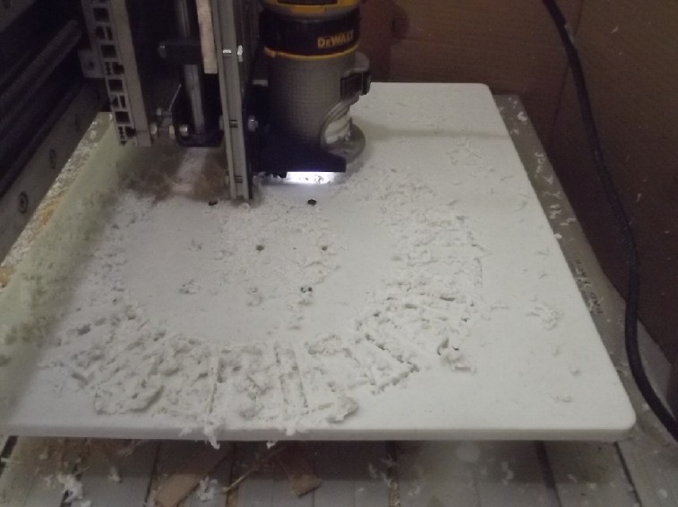
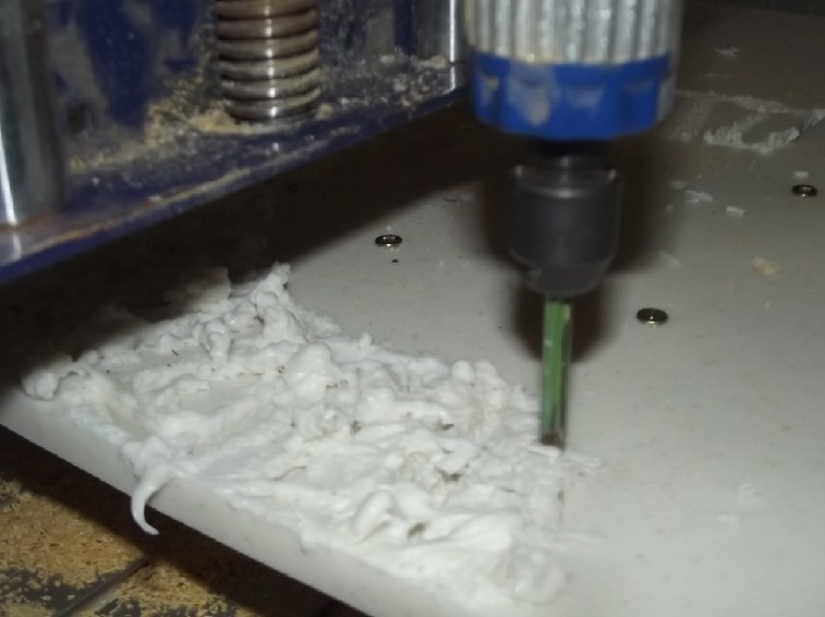 [21st] I did
that. The chief problem seemed to be that no matter how
little or much depth was being cut, the plastic melted almost back into
place as the router went by. I surmise that it is turning much too fast
even for a little 6mm diameter bit, but this router has only one speed.
What a cheap piece of crap for an otherwise nice CNC table! Half way
around, I guess as the bit warmed up - it started melting the plastic
into blobs. Where it came near the edge of the piece, a big blob
actually went over the edge and dripped down over the side. A little
farther on it got stuck - the router stalled! Ouch! Apparently I'm not
cutting plastic with this crappy router. I knew from the moment I saw
it that I didn't like it with its tiny body diameter and no speed
control, but only now that I try and use it are my worries confirmed.
It occurred to me afterward that I could have paused the program,
turned it off and let it cool. But I didn't know it was going to fail.
And that was only the first, painfully slow, pass of four or five! What
were my chances of getting a good finished jig?
[21st] I did
that. The chief problem seemed to be that no matter how
little or much depth was being cut, the plastic melted almost back into
place as the router went by. I surmise that it is turning much too fast
even for a little 6mm diameter bit, but this router has only one speed.
What a cheap piece of crap for an otherwise nice CNC table! Half way
around, I guess as the bit warmed up - it started melting the plastic
into blobs. Where it came near the edge of the piece, a big blob
actually went over the edge and dripped down over the side. A little
farther on it got stuck - the router stalled! Ouch! Apparently I'm not
cutting plastic with this crappy router. I knew from the moment I saw
it that I didn't like it with its tiny body diameter and no speed
control, but only now that I try and use it are my worries confirmed.
It occurred to me afterward that I could have paused the program,
turned it off and let it cool. But I didn't know it was going to fail.
And that was only the first, painfully slow, pass of four or five! What
were my chances of getting a good finished jig?
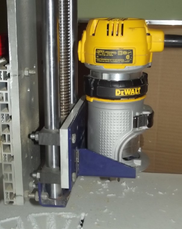
I had a look at my DeWalt woodworking router. It had a
variable speed dial. It would have to have a mounting made to attach it
to the CNC table carriage, and I would have to recalculate all the
dimensions again for a .25 inch bit instead of 6mm. This is definitely
a setback. As long as I don't move the piece of plastic on the CNC
table I can probably manage to have it cut in "exactly" the same places
again and haven't lost it. It's my only piece and there's nowhere to
buy another one around here.
I took the crap router out of its cradle (if that's the
right word) and noticed that the DeWalt's base would fit in it if I
chopped off a bit of the bottom flange on each side and at the back,
and drilled four holes in the cradle bottom to match the DeWalt's
threaded bolt holes. After the cutting, careful drilling and then a
bunch of filing anyway to get the holes to line up, it seemed to
fit nicely. Much simpler than making a whole new "cradle".
 Then problems started appearing. Being held at its bottom
instead of in the middle, the carriage wouldn't lower down anywhere
near the worktable. In fact, the router bit couldn't go below the
carriage bottom. I finally made a plate to extend the router cradle
down several inches. But the vertical carriage holder stuck into the
path. So I used both the original plate, as a spacer, and the new one.
And
my off-position holes weren't the first ones on this machine: the
original plate fit better one way around than any other way. I used
1/4" bolts to hold the cradle to the new plate. The ones I could see
just cleared the bottom of the carriage. The ones on the other side hit
it and jammed. I had to take it apart again and redo that side with
flat head (AKA countersunk) bolts. (It turned out a screw was loose at
the bottom. It fell right out later.)
Then problems started appearing. Being held at its bottom
instead of in the middle, the carriage wouldn't lower down anywhere
near the worktable. In fact, the router bit couldn't go below the
carriage bottom. I finally made a plate to extend the router cradle
down several inches. But the vertical carriage holder stuck into the
path. So I used both the original plate, as a spacer, and the new one.
And
my off-position holes weren't the first ones on this machine: the
original plate fit better one way around than any other way. I used
1/4" bolts to hold the cradle to the new plate. The ones I could see
just cleared the bottom of the carriage. The ones on the other side hit
it and jammed. I had to take it apart again and redo that side with
flat head (AKA countersunk) bolts. (It turned out a screw was loose at
the bottom. It fell right out later.)
Finally I realized that the power switch on the router was
hard against the plate. And it must have been held in its middle
position because I tried to simply leave it On and use the switch on a
power bar, but it wouldn't run. At that point the day was done -
overdone because I was neglecting everything else I should be doing. So
much for a two hour morning job!
[22nd] One more time... take apart and
put back together, this time
cutting a big square out of the new plate to accommodate the On-Off
switch. (Oops no pictures)
The other half of the problem was the trig. Then trial runs again
and then hoping the previous routing's gouges and blobs of plastic
wouldn't mess things up. The 6mm bit wouldn't tighten down in the
DeWalt's 1/4" collet chuck - one may hope, but not a surprise. It
looked like the other router's 6mm collet was the same O.D. and would
fit in the DeWalt's housing. But the collet in the DeWalt was locked
into place! It would spin, but even tapping it with a hammer wouldn't
push it out. Crap! And the threads were wrong for the other router's
collet holder. I'm not a fan of either the imperial or the metric
system, but mixing them up 50 years after Canada supposedly went metric
sure makes a lot of trouble. Prices in the grocery are still in pounds,
or "bilingual". 12mm plywood is 4 by 8 feet in size.
Then I looked on line for a 6mm router bit with a 1/4"
shank. Sure enough, they have them. (Why did I never search two years
ago for a 1/4" bit with a 6mm shank?) I ordered a few, but of course
they will take time to arrive.
So I redid the gcode for 1/4 inch router bit. While I was
doing that and thinking about how hard it seemed to be to rout that
dense, 12mm thick piece of HDPE plastic, I came up with the
idea to make a thinner but still substantial jig by melting down a
couple of old 5 gallon HDPE bucket pieces in one of my plastic molds in
the kitchen oven. Or some of my odd scraps or router shavings of
UHMWPE? (I saved them in a bucket for something like this!) Maybe about
4-5mm thick? The big disk mold should be good!
[23rd] UHMW - ultra high molecular weight polyethylene. Millions of
atoms per polymerized molecule. I didn't really think about it...
polyethylene is polyethylene, right? But as I think about it, I had
never tried remelting UHMW before. I thought melting it would be much
the same
as HDPE - high density polyethylene.
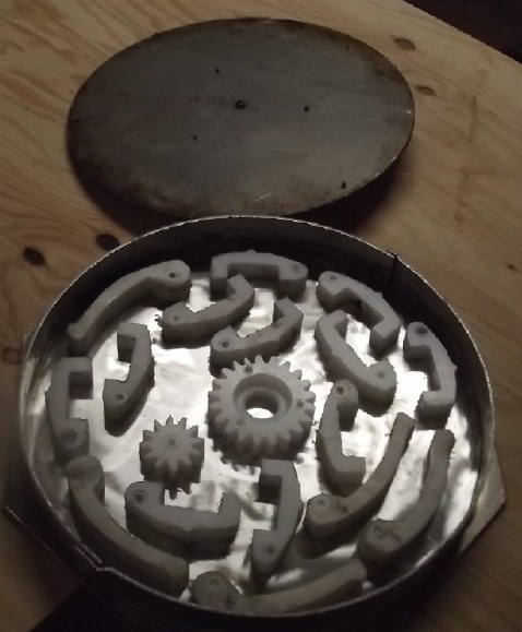 I
used some pieces from previous experiments out of the
bucket, thinking that shavings might end up full of air bubbles. First
I repolished the bottom of the disk mold because there were bits of
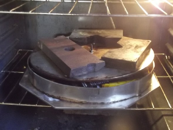
PP(?) stuck to it from previous ropes off the beach. (I suspect some of
them weren't PP.) I put a concrete brick under the oven rack to help
support it. Then the mold and about 30 pounds of weight on top, that
being my hazy memory of a good amount for this mold. From TE News #178
I found the right temperature was around 400°F. I set the oven to that
and put it on for an hour. After an hour the lid hadn't sunk down much
if at all. I put it on for another hour. UHMWPE Does melt at the same
temperature as HDPE, doesn't it?
I
used some pieces from previous experiments out of the
bucket, thinking that shavings might end up full of air bubbles. First
I repolished the bottom of the disk mold because there were bits of
PP(?) stuck to it from previous ropes off the beach. (I suspect some of
them weren't PP.) I put a concrete brick under the oven rack to help
support it. Then the mold and about 30 pounds of weight on top, that
being my hazy memory of a good amount for this mold. From TE News #178
I found the right temperature was around 400°F. I set the oven to that
and put it on for an hour. After an hour the lid hadn't sunk down much
if at all. I put it on for another hour. UHMWPE Does melt at the same
temperature as HDPE, doesn't it?
It didn't help. Then I let it cool (over an hour) to where
I wouldn't burn something or myself and opened it. Some of the pieces
around the edge were a little deformed; that was it. I guess UHMW needs
a higher temperature? 500°F had scorched the HDPE at the time of TE
News #177. I reassembled it and put it back on for an hour at 450°.
That didn't seem to help either.
Then I looked it up on line. Supposedly it melts around
270°F! I upped the oven to 475°F anyway, for an hour. If it melts at
270°, it's sure one awfully viscous liquid! Maybe it needs 300 pounds
of weights instead of 30?
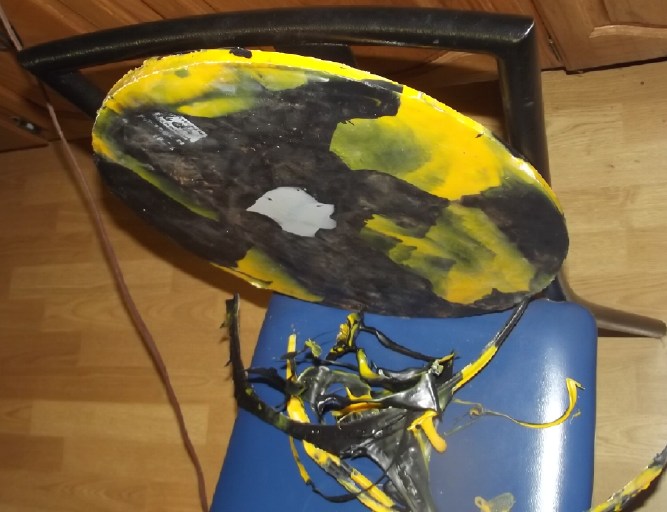
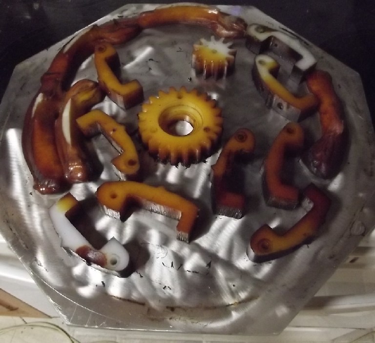 When I took it
out, some pieces had sagged but others
hadn't even deformed. They all looked pretty scorched. So I went back
on line and found this: "Unlike most thermoplastics, UHMW plastic does
not become a liquid when heated above its "melting point". Because of
its high melt strength, it can be handled and shaped above its
crystalline melting temperature of 265°F." Yep, is is indeed an
"awfully viscous liquid". It would seem then that it didn't need
anything like such a high temperature, but it does need hydraulic
pressure or that "300 pounds" of weight to form it. My simple pan
molds, and my oven, couldn't possibly take that sort of stress. I guess
I won't be trying UHMW again. Not without a new plan, anyway. At least
it didn't have an odor - or burn - when heated so hot.
When I took it
out, some pieces had sagged but others
hadn't even deformed. They all looked pretty scorched. So I went back
on line and found this: "Unlike most thermoplastics, UHMW plastic does
not become a liquid when heated above its "melting point". Because of
its high melt strength, it can be handled and shaped above its
crystalline melting temperature of 265°F." Yep, is is indeed an
"awfully viscous liquid". It would seem then that it didn't need
anything like such a high temperature, but it does need hydraulic
pressure or that "300 pounds" of weight to form it. My simple pan
molds, and my oven, couldn't possibly take that sort of stress. I guess
I won't be trying UHMW again. Not without a new plan, anyway. At least
it didn't have an odor - or burn - when heated so hot.
I guess I should use HDPE
from old 5 gallon buckets per my
first thought. Another website differentiates between them that
HDPE "is easily remoldable", even ten times. At least I know it seems
to melt down and form okay at 400°F.
 [24th] I
molded a disk with HDPE - A black 5 gallon bucket and a yellow lid
for the same type. I put the two colors in somewhat randomly. I tried
cutting the bucket with the foam cutter. It cut slowly and made smoke.
That might have been all right, but the cut sealed itself up again
behind the hot wire. It was a fair struggle with chisel to pry it
open and extract the cutter. After that it was the skillsaw and then
the radial arm saw to get the curved pieces down to some semblance of a
reasonable size to fit in the mold.
[24th] I
molded a disk with HDPE - A black 5 gallon bucket and a yellow lid
for the same type. I put the two colors in somewhat randomly. I tried
cutting the bucket with the foam cutter. It cut slowly and made smoke.
That might have been all right, but the cut sealed itself up again
behind the hot wire. It was a fair struggle with chisel to pry it
open and extract the cutter. After that it was the skillsaw and then
the radial arm saw to get the curved pieces down to some semblance of a
reasonable size to fit in the mold.
I wanted to put the clamps on the sides of the mold, but
the lid wouldn't close down to where the sides were. If I put the
clamps on the lid wouldn't fit in and press down on the plastic as it
melted.
 I left it in the
oven at 400°F for maybe around 90 minutes,
returning after 20 or 30 to push the lid down. I had intended to put
the clamps on at this point, but I decided not to bother. This led to a
lot of dripping HDPE oozing out the edges. (I didn't return when it
turned off, so I don't know how much longer it was in. The HDPE was
definitely
well melted. It came out 6mm thick at one side and 15mm at the other.
Ideally it should have all been about 6mm. Obviously I used way too
much plastic - maybe 3 times too much. The 6mm minimum depth is set by
the screws in the lid hitting the bottom plate, otherwise it might have
been vanishingly thin on one side and even thicker on the other. (If I
had wanted a piece this thick, I would have used longer screws.) I did
a lot of cutting with scissors both left and right handed to get all
the oozed out plastic off from around the edges.
I left it in the
oven at 400°F for maybe around 90 minutes,
returning after 20 or 30 to push the lid down. I had intended to put
the clamps on at this point, but I decided not to bother. This led to a
lot of dripping HDPE oozing out the edges. (I didn't return when it
turned off, so I don't know how much longer it was in. The HDPE was
definitely
well melted. It came out 6mm thick at one side and 15mm at the other.
Ideally it should have all been about 6mm. Obviously I used way too
much plastic - maybe 3 times too much. The 6mm minimum depth is set by
the screws in the lid hitting the bottom plate, otherwise it might have
been vanishingly thin on one side and even thicker on the other. (If I
had wanted a piece this thick, I would have used longer screws.) I did
a lot of cutting with scissors both left and right handed to get all
the oozed out plastic off from around the edges.
I was however going to try routing it to make the magnet
jig.
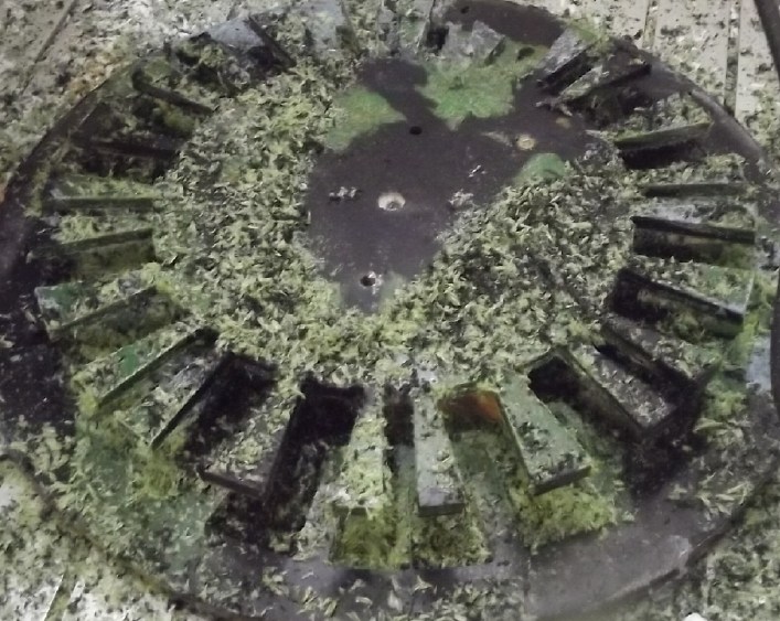
 [January 26th]
I tried again to route the original piece of HDPE. I
tried cutting part way through but concluded that the only way it might
work was cutting all the way through at once. This time the CNC table
ran the course, but even with the router on its lowest speed the
plastic melted back together behind the cut and it was a disaster. I
cut off the piece but it was clear that it wasn't going to clean up
nicely in any length of time I wanted to devote to it. And already one
leaf had broken off the jig.
[January 26th]
I tried again to route the original piece of HDPE. I
tried cutting part way through but concluded that the only way it might
work was cutting all the way through at once. This time the CNC table
ran the course, but even with the router on its lowest speed the
plastic melted back together behind the cut and it was a disaster. I
cut off the piece but it was clear that it wasn't going to clean up
nicely in any length of time I wanted to devote to it. And already one
leaf had broken off the jig.
I had only routed UHMW before, not HDPE. I had thought it
would be the same, but considering how differently they behaved in a
mold in the oven, I figured it was the material: HDPE couldn't be
routed except at a router speed slower than even my adjustable router
would
go. Hmpf! That meant that the new piece I had molded wouldn't work
either.
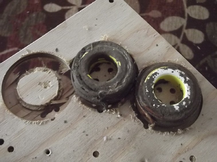
 I could buy
some very small pieces of UHMW from just one store
on AliExpress. One arguably just big enough to "make do". And wait
weeks
for it to come. I took an earlier molded disk of polypropylene (from
ropes off the beaches) and tried that. It Looked the same as the HDPE,
but the chaff clogging the gaps behind the cutter pushed out easily,
and when it had run the circle, the outer ring dropped away. Now the
only problem is that epoxy seems to adhere to PP -- at least, to PP
fabric. But I was just reading something on line about how the fabric
fibers
behave differently from the solid block material. One website says you
can epoxy PP, another says it won't stick. I hope I won't have to
chisel it off the rotor once I have the magnets on!
I could buy
some very small pieces of UHMW from just one store
on AliExpress. One arguably just big enough to "make do". And wait
weeks
for it to come. I took an earlier molded disk of polypropylene (from
ropes off the beaches) and tried that. It Looked the same as the HDPE,
but the chaff clogging the gaps behind the cutter pushed out easily,
and when it had run the circle, the outer ring dropped away. Now the
only problem is that epoxy seems to adhere to PP -- at least, to PP
fabric. But I was just reading something on line about how the fabric
fibers
behave differently from the solid block material. One website says you
can epoxy PP, another says it won't stick. I hope I won't have to
chisel it off the rotor once I have the magnets on!
[27th] I realized that if I
mounted the
jig a little off the rotor with washers on the bolts, it should get no
epoxy on it
to stick it to the rotor. Or at least not much. So the PP
jig should work! That hurdle finally overcome, it was time to epoxy
magnets onto the rotor. First, check them out... Plenty of 1 x 2 x 3/8"
magnets. Not a lot of 1 x 2 x 1/2" left, but plenty for the eight 1/2 x
2 x 1/2 sideways magnets to make it "Hallbach" configuration.
Especially as I was cutting four in half to make the eight.
Then I started thinking 3/8" magnets were a little thin.
The
magnetic
field
wouldn't be as deep as with 1/2". Would stacking them up to make 3/4"
be too thick? We want TORQUE. Torque comes from FLUX. Then I'd have to
use the full size 1 x 2
x 1/2" ones on edge for the sideways ones? But then unless I cut them
down to 3/4", they'd stick out 1/4" above the others. Possible with
axial flux's wide flux gap, but probably better if they don't stick
out. Or should I cut them as 1/2" tall after all? Then they'd be 1/4"
shorter than the others. Would that provide sufficient "Hallbaching"
flux? Considering the flux 3/4" thick will have already, I figured that
would
be "good enough".
So, next job: cut four magnets in half.
Then check out TE News #162 where I remember I had hit on
a more
secure way to glue the magnets to the rotor. It was to roughen the
surface of the rotor and of the magnets so the epoxy has a super grip,
and to put lots of epoxy around the magnets, 3 or 3 coats. This would
include roughing up all sides of the magnet except the top, and if two
are to be stacked, to also rough the top of the lower one. The rotor I
figured was already rough with surface rust. The epoxy should really
grip
that. All I did to it was rub it with a cloth to remove loose rust.
There wasn't much - the cloth just looked a bit orange.
[27th] Cutting supermagnets isn't
recommended... but. They're to tough to cut with anything but a zip
disk. And tedious with that. Since I want them to work, I can't
overheat them. That means cutting a stroke, waiting a moment for the
heat to diffuse from the cut into the rest of the magnet, doing this a
very few times, and then leaving it for ten minutes for the whole
magnet to cool. I may be being overcautious, but that's how I'm doing
it. And they're still almost bound to demagnetize some right by the cut
line.
I split one magnet, and then thought, "Why am I doing 1/2
measures? Why not just order some 2 x 3/4 x 1/2" on line and wait for
them to arrive?" But when I looked, there weren't any that size. I
could have made them up from 3 or 4 thin ones that were 2 x 3/4".
Sanding off all those faces (to roughen them) and then epoxying them
together sounded as tedious as what I was doing. And I would have to
wait for them to ship. I guess I should slice eight of the "regular" 2
x 1 x 1/2" down to 2 x 3/4 x 1/1". Twice as much tedium.
Then I looked on AliExpress.com . There were more
sizes, but they were all metrick. There were some 50 x 20 x 10mm - okay
for length and only slightly tall (.787" instead of .75"), but pretty
skinny (.394" instead of .500"). N35 wasn't very strong... wait, more
searching found some N52. That convinced me. FLUX, TORQUE! They would
be loose side
to side in the slots but if I glued them on first they wouldn't try to
flip over. Of course now I have to wait a month or so for them to
arrive. At the rate I'm going I can work on the stator for a month. Any
"spare" time I have I can get the faraday cabin farther along.
 [28th] I
decided to put the first layer of magnets on anyway, with some
spacers to hold the positions of the sideways magnets. If I need to
I'll clamp those down until the epoxy sets. So I spent the
day sanding the slick epoxy coating on all six sides of 16 magnets with
#120 sandpaper so they would adhere better to the new epoxy and have a
strong grip on the rotor. Then I got out what I think is the best
epoxy, "System Three
for oily hardwoods" and epoxied them to the rotor. Two got away on me
and clamped on top of other magnets. (& gave me a blood blister on
my thumb.) As I was trying to pry the first one off, I had the thought
that since I was going to have two layers anyway, and it already had
epoxy on the bottom, I should just leave it. When I ran out I got out
two more magnets and filled the last two positions.
[28th] I
decided to put the first layer of magnets on anyway, with some
spacers to hold the positions of the sideways magnets. If I need to
I'll clamp those down until the epoxy sets. So I spent the
day sanding the slick epoxy coating on all six sides of 16 magnets with
#120 sandpaper so they would adhere better to the new epoxy and have a
strong grip on the rotor. Then I got out what I think is the best
epoxy, "System Three
for oily hardwoods" and epoxied them to the rotor. Two got away on me
and clamped on top of other magnets. (& gave me a blood blister on
my thumb.) As I was trying to pry the first one off, I had the thought
that since I was going to have two layers anyway, and it already had
epoxy on the bottom, I should just leave it. When I ran out I got out
two more magnets and filled the last two positions.
I'm not as well organized for this as I once was. I didn't
clamp the rotor down, so it could turn and jump up with magnetic
forces, and I didn't have a wooden jig that covered the magnets
adjacent to the one I was trying to mount. After the first magnet got
away I hacked up my old wooden jig and it helped, but it didn't fit
properly since it was for the original 10 inch rotors with twelve
magnets. With the bottom layer (& 2 on top) done I left it for the
epoxy to set.
 [29th] In getting more 2 x 1 x 3/8" magnets
from the box I had to separate three
adjacent rows. I pried off the first row of 7 without trouble. I wanted
to put the two longer rows, ten magnets each, in a vise, but I thought
about how hard they would clamp onto that vise... and tried by hand.
They came apart at one end, then suddenly both rows folded and two
caught
my finger, completely pinching out a chunk of flesh. (More than skin
deep.) Bleeding
was profuse. I quit for a while. (None of four pics was in focus. Of
course new tissues have to grow in from the sides to replace what was
lost. It still hasn't healed, but seems to be headed in the right
direction with some massage - Feb. 7th Getting there - Feb 9th.)
[29th] In getting more 2 x 1 x 3/8" magnets
from the box I had to separate three
adjacent rows. I pried off the first row of 7 without trouble. I wanted
to put the two longer rows, ten magnets each, in a vise, but I thought
about how hard they would clamp onto that vise... and tried by hand.
They came apart at one end, then suddenly both rows folded and two
caught
my finger, completely pinching out a chunk of flesh. (More than skin
deep.) Bleeding
was profuse. I quit for a while. (None of four pics was in focus. Of
course new tissues have to grow in from the sides to replace what was
lost. It still hasn't healed, but seems to be headed in the right
direction with some massage - Feb. 7th Getting there - Feb 9th.)
 Of course one
must take responsibility for one's actions and safety. But there are
always contributing factors. I must say I have never thought much of
the hollow rectangle plastic spacers used to separate these neo
magnets. And this is by far the most common size magnet for many
electric motor and generator projects, deserving extra consideration.
The spacers
don't even extend out to the edges. Perhaps this is done for some
automatic pick and place tongs that grab magnets from stacks, but they
are needlessly hazardous to human handlers. By not coming to the edges
they will spit out one side and the magnets snap together if there's
sideways pressure on the stack.
Of course one
must take responsibility for one's actions and safety. But there are
always contributing factors. I must say I have never thought much of
the hollow rectangle plastic spacers used to separate these neo
magnets. And this is by far the most common size magnet for many
electric motor and generator projects, deserving extra consideration.
The spacers
don't even extend out to the edges. Perhaps this is done for some
automatic pick and place tongs that grab magnets from stacks, but they
are needlessly hazardous to human handlers. By not coming to the edges
they will spit out one side and the magnets snap together if there's
sideways pressure on the stack.
The spacers should cover five sides of the magnet - one
face and the edges. That way the stack is enclosed except for the end
magnet, preventing the powerful forces when two magnets actually touch.
The spacers can't slide out and even if the
magnets snap over sideways anyway, there's still a spacer between them.
The end magnet can still be twisted sideways and then pulled off the
end without danger that the plastic separator will come loose and shoot
away before the magnet has been removed.
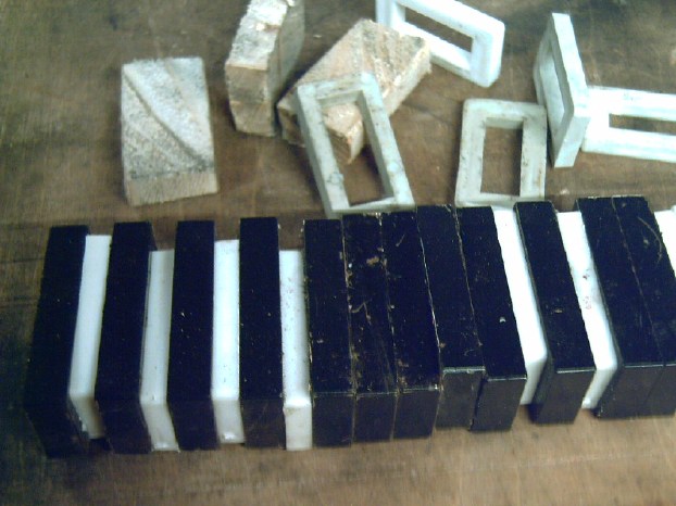
Here one can see all the spacers that snapped out in my
accident. These magnets are now difficult to separate. What cost a
better cheap piece of plastic for safety?
(Somehow I was short a couple of spacers while doing the
rotor magnets. My wooden ones shown at least extend to the edges and
hold the
magnets farther apart.)
Well, I bought these a decade ago. Hopefully the magnet
makers have already figured this out, because doubtless I'm by no means
the only person to have injured myself with these "accidents waiting to
happen" magnet spacers. (And of course, these powerful magnets are
"accidents waiting to happen" whenever they are being handled!)
I had intended to take the
placement jig off and raise it
up for the second layer of magnets. But when the magnets were being
placed they were smearing epoxy onto it. Some of it seemed rather well
stuck and I decided to leave it where it was. The first two second
layer magnets placed by accident were exactly on top of the first, so
perhaps they didn't need the jig. But the sideways magnets, when they
arrived, would probably want it. It may only come off in pieces and
even with scraping some away. I wish I had had some UHMW instead of PP.
I pried 7 more magnets off the somewhat
disordered mass by having the clump clamp onto my "anvil" and pulling
them
away with visegrips. That was safer but the visegrips broke little
chips off some of the magnets.
After the epoxy was [presumably] set, I put the
hyper-magnetic rotor away in a box to await delivery
of the eight "sideways" Hallbach effect magnets. The magnetic depth of
field of this rotor was going to completely encompass the one inch
thick stator coils and their iron powder toroid cores. I look forward
to torque of over 50 foot-pounds from this motor; with the 5:1
planetary reduction, 250+ to the wheel. Probably 20 HP (15 KW) peak at
3500 RPM. Surely not a "muscle car", but with that electric power plus
"ultra-efficiency" of both the motor and the connection to the wheel,
the lightweight Sprint car should have some "zip" to it!
[31st] Having routed the magnet template
out of polypropylene (PP) it
occurred to me that if I was routing stator plates out of 1/2" plywood
instead of molding them from PP, I could just as well route them from
1/2" flat a PP slab, and have it made out of PP after all. My molded PP
pieces had too many flaws and I decided they weren't good enough for
this purpose. On line PP
sheet was much scarcer than other plastics, but available at a
specialty place or two. The best choice looked like 1/2 a sheet, 4 by 4
feet, for about 200 $US. There was one other place I had opened a web
page, and I looked more closely before (I thought) I would close it. It
was BuyPlastic.com , and they offered something called Polypropylene
Copolymer (PPC) sheets:
"softer but tougher and more durable than homopolymer
polypropylene." And good to 100°C, even 150° for a short period.
So, even better than polypropylene!
The copolymer monomer is ethylene. Somehow the mix of propylene and
ethylene gives it different characteristics to either single polymer.
So the motor will have the inert, stiff, dimensional
stability of plastic (rather
than plywood & humidity) and a higher temperature rating than other
plastics! Cut to the size you ask. They had 1/2 inch thick sheets! I
ended up ordering a full 48 x 96 inch sheet, cut into three pieces 32"
x 48".
How Big Diameter?
[19th] I tried several times to decide how big to make it. At one point
I was up to 400mm. Finally, setting up coils, fake magnets and rotors,
I decided 322mm or 12.68" was my best estimate of a minimum good outer
diameter, and to keep it as small as possible.
In theory, I Could have got the magnet rotor down to 12" diameter. 16
magnets
were an inch wide and the 8 sideways ones 1/2 inch, making 20 inches.
The inner diameter (2 inch long magnets) would thus be 8 inches. π * 8
= 25.13", leaving 5.13"/24=.21" between magnets at the inner ends. (No
doubt the placement jig leafs would bend and break off!) Another way to
shrink it
would have been to use eight 1/2 x 2 x 2" magnets instead of sixteen
1/2 x 1 x 2". Then there would still be 20 inches around an 8 inch
circumference, but only 16 magnets for 5.13"/16=.321" between them at
the inner ends.
But come to think of it, it was actually the stator coils
arranged around a
disk that determined the minimum diameter. The cores are only 2" O.D.,
but I plan to use 27 turns of #11 AWG magnet wire on each coil. That's
three layers of fat wire, which expands them to almost 2.7", and the
coils should have at least a little space between them. At 12" they
would be virtually touching each
other, if not overlapping. So the 12.68" (to the outsides of the cores)
is actually pretty
minimal.
If one had a research facility with several workers
multiple diameters and design variations could be tried and tested. One
might discover an optimum diameter for torque, speed, power, RPM - and
cooling - was a little wider and more spaced out. Or at least run some
computer
modeling. (But if like magnet poles are too close together they may
start to
gradually
demagnetize each other, which computer models probably won't account
for. A big advantage of axial flux is that with the huge flux gap
(around 1/2"), the coils won't gradually demagnetize the rotor magnets
as they are said to do with radial flux BLDC designs, which invariably
have tiny flux gaps.)
But the 322mm O.D. of the magnets and coils is
probably close enough to optimum for power and torque. And anywhere
within reason is going to be 95% peak
efficiency and higher efficiency at heaviest loads (75+%?) than most.
Stator "Mock Up"
[Feb. 1] While the motor is now to be made of PPC I had wanted to rout
a sample out of plywood anyway to see how everything fit together. I
added one more item to the G-code file: holes for the coil wires in
order that they poke through the stator wall and will be wired on the
outside where there is plenty of room. Also they can be easily
reconfigured for bipolar operation if unipolar isn't working out. (It
is after all an untried concept.)
After a couple
of false starts and then adjustments to the CNC machine
configuration, I tried to test rout one from 12mm plywood even tho that
now wouldn't be the actual material. The center hole was routed in
three passes, then bolt holes and coil wire holes were drilled - as
seen.
But the routed coil contours cut too deep. On the flat the
bottom was very thin, and where the plywood curled up just
slightly on one side, the bit went right through.
(The outer corner holes show that the wood was nothing like exactly
centered. Oops.)
It gave me just enough of a
sample to
see how the coils would fit. They were closer together than I thought,
but okay - they wouldn't touch.
(Too bad I can't use any of these old coils, already made,
but I want 27
turns of #11 wire on each coil on this motor instead of 21. It's still
just three layers, so the outer diameter will be the same. Also I want
to
mix the ilmenite in with the epoxy to have it well embedded throughout
the wires.) I have lots more wire and cores.
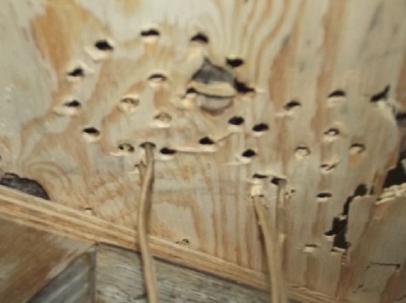 The coil wires sticking
through their holes gives lots of room for wiring them.
The coil wires sticking
through their holes gives lots of room for wiring them.
Other
"Green"
&
Electric
Equipment
Projects
"Faraday
Cabin"
Construction (long continued)
[1st] Along with making the plastic cutting hot wire 'saw' and doing
some
insulating described in the next article below, Dan came over and we
put in the wall 2 by 6's for the floor
in the southwest quarter of the cabin. Lots of checking for level.
Hopefully marbles won't roll across this floor! [6th] I bought
metal joist hangers.
[9th] I put in
the first piece of the other end
and the next 5 floor joists. Each one a custom cut of course. I seem to
be cursed with constructions where nothing is ever quite level, square,
plumb, flush, true, vertical or on standard centers. (First an 1879
house from before there was plywood and drywall dimensions, that had
settled a lot, now this post & beam cabin.) And the lumber I cut
with the handheld bandsaw sawmill[*] in 2018-2020 is never
exact
dimensions either, except when I occasionally (& laboriously) plane
some pieces flat, smooth and regular.
Next I wanted 'no floor' under the stairs to make it a
step down into a deeper utility closet. So I needed some 8-3/4 foot 2
by 6's and had only 12 and 16
footers. Whether bought or milled myself, this much waste pains me! And
then I'd run out of longer ones before the last floor is done.
There was one last stack of odds & ends under cover
outside. One day it wasn't raining. I uncovered it and found enough odd
cuts and rejects in lengths close to my needs - mostly long enough with
only a couple a bit too short. Many were cut on three faces with
irregular raw log on one edge. These could be ripped down into widths
that would work. (They didn't have to be exact 2 by 6'es; they could
stick down some.)
I brought them in and cut three. But there it sat. I spent
much time on the new motor instead, then came snow and bitter cold,
continuing into
February.
[*] See various TE News issues from 2018-2020 for details on the
development of this fabulous tool - a 120V plug-in sawmill with
virtually no kerf!
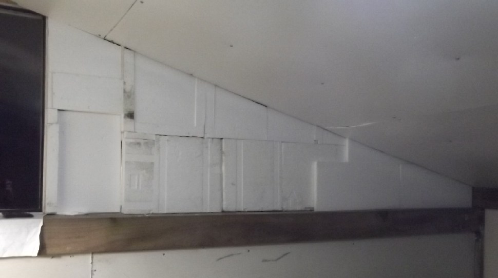 [22nd] I
turned on heaters so it was tolerably warm to work, and
insulated the top part of the west wall in the upstairs room with most
of the rest of the foam cooler pieces. They were 2 inches thick. I did
some
insulating with some 1 inch thick pieces in front of those making it 3
inches, but it's probably overkill and I just used up the pieces I had
brought upstairs. In spite of theoretical rating for this 2 inch foam
being maybe R9 to R10 (and an air gap adding R1), somehow I can't help
but
think it's better insulation than R12 fiberglass batts. I could be rong.
With an extra inch it's even better.
[22nd] I
turned on heaters so it was tolerably warm to work, and
insulated the top part of the west wall in the upstairs room with most
of the rest of the foam cooler pieces. They were 2 inches thick. I did
some
insulating with some 1 inch thick pieces in front of those making it 3
inches, but it's probably overkill and I just used up the pieces I had
brought upstairs. In spite of theoretical rating for this 2 inch foam
being maybe R9 to R10 (and an air gap adding R1), somehow I can't help
but
think it's better insulation than R12 fiberglass batts. I could be rong.
With an extra inch it's even better.
I'll just stuff in some plywood held in place by mouldings
to cover it. Nothing structural here. With the floor and two interior
walls uninsulated and big
cracks around the door, it didn't make the room noticeably warmer when
it really got cold. -7° only went up to -2° in an hour with 1450W of
heaters turned on.
Hot-Wire
Plastic
Foam
Cutters
Hot Wire "Saw" to Cut Plastic Foam: Project in a day!
I have far too many projects that drag on and on and seem
to rarely come to completion. This one surprised me by actually
taking Less time than I expected - an hour!
Having filled a few wall stud spaces
with foam rubber and then polyethylene foam, I asked myself why I would
want to work with fiberglass? I would happliy do the rest of the
structure with these friendlier materials.
Fiberglass wool batts: R 3.5 (per inch - R 12 in 2 by 4 wall cavities.)
Foam rubber: R ?
Polyethylene Foam: R 3
Beady Styrofoam: R 4
Extruded polystyrene: R 5
I figure the polyethylene foam is probably better than
fiberglass because it stops the air movement better. I could be wrong,
but 3 inches thick plus "R 1" for a 1/2 inch air gap should be at least
R 10. 3 inches of beady styrofoam would be R 13 and extruded would be R
16.
I put an ad in Haida Gwaii Trader, "Wanted: Plastic Foam -
Flat pieces to use for wall insulation" Someone replied that they had
some. I went and got it, but it was mostly molded packaging pieces, not
flat. The lady said she had been planning to make a hot wire cutter to
cut it up but never got around to it. I took their lumpy pieces, but
this idea was the important thing.
Then my neighbor said he had some that he was going to
insulate a shed with. He saved them from shipments coming in at work.
They were smallish sheets of one inch thick beady styrofoam. [3oth] I
put some pieces of it into two wall cavities (14 inches by 12 feet
tall), but the styrofoam was notably harder to cut than the
polyethylene foam and less forgiving of slight errors in size - it
wouldn't just squish in. It took hours and I only got the two cavities
half filled. It just took too long, especially cutting them up with a
knife and not always getting "perfect" cuts.
[Dec. 31st] I phoned and then went to the recycling center in town,
where I
heard the landfill shipped all their foam to. (Presumably to ship it
all to Vancouver, burning more petroleum product in fuel than is
contained in the plastic, to add to the growing mountains of plastic
garbage there.)
He reminded me that there were no fire retardants in these
plastics. I had already decided that was "okay" - a small risk. With
the outside of the building being metal, a fire outside certainly
wouldn't light the "Faraday Cabin" walls or ceiling. Anywhere there
might be heat inside I would have gyproc wallboard. The thick floor
tiles are presumably fire resistant. The building would have to be well
on fire already before it could get into the walls.
The best looking pieces were a big bag of square sided
cooler boxes of extruded polystyrene, said to be from meds shipped to
the drug store at controlled temperatures(!) All sides were about 2
inches thick so just one layer of those and one 1 inch layer to fill
each wall cavity. I decided I needed to make the hot wire cutter that
lady mentioned, to cut things like these into flat pieces. The bag of
coolers was aboput 4 x 4 x 6 feet. I said I would come back with my
trailer and take the bag. I'll want more bags after that.
[January 1st] I had some
ni-chrome resistance wire that I got a few
years ago to make plastic recycling heaters, before I got the idea just
to melt plastics in an oven. I cut a foot long piece and connected it
with alligator clips to a power supply. It got really hot. I turned the
power down to 5 volts and, holding the alligator clips and a piece of
plastic (did I have three hands?) I pushed it in. Wow! It went like the
proverbial "hot knife through butter!" I pulled back and it came out
another way, cutting out a triangular piece.
Then I made a "hacksaw" piece of plywood and put bolts
through the ends. I cut a longer wire to fit and attached it. I put in
a couple of cable staples to hold the alligator clip leeds better. Then
I took it with the power supply out to the cabin and cut a piece of
foam. All in an hour! The setting was 14 volts, where it drew about
2-1/2 amps. That's just 35 watts.
I found the
best way to cut was to lay the
saw's wire on
the line to be cut, then turn the power On. The weight of the saw alone
pushed it through. The one inch thick pieces took about six seconds.
1 - nothing
2 - starts to melt
3 - 1/4 inch melted
4 - 1/2 inch
5 - 3/4 inch
6 - Through! Turn power Off.
This way there was minimal smell from the plastic and it
cut fast.
I did the
second of the two tall wall cavities behind the south door
in maybe an hour
and a half. I found it hard to cut pieces longer than the
blade straight, so I used smaller pieces and made more cuts than I
would have.
And three layers of one inch foam is substantially more work than
fewer, thicker layers. I
may make a longer "saw".
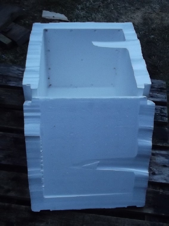 I tried
cutting a side off a cooler box by hand. It was
pretty wavey.
I tried
cutting a side off a cooler box by hand. It was
pretty wavey.
I
was trying
to figure out how to make a jig to cut the
sides off straight. I had one plan, then I realized that boxes would
hit the handle. In the evening I thought I could just C-clamp the saw
to the side of a workbench that had 1 by 4 sides under the edge.
This worked quite well. I set the plastic right in front
of the "blade", turned on the power and melted through the wall
thickness (15 seconds?) then drew the piece back and shut off the
power. I had to shut off the power between cuts because the wire sagged
when it was hot. It sprung back up as it cooled.
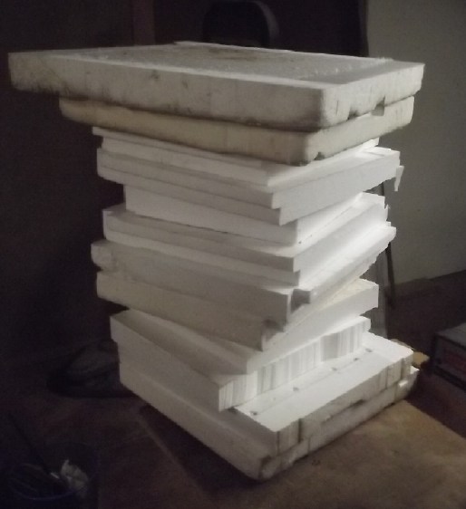 By the time I
retired for the night (still my 70th birthday, January 1st!) I had cut
two cooler
boxes into 12 fairly flat pieces.
By the time I
retired for the night (still my 70th birthday, January 1st!) I had cut
two cooler
boxes into 12 fairly flat pieces.
[2nd] I filled one wall cavity with
cooler pieces. They're two inches
thick; I think R11 with the thick air gap. I'm debating whether I
should add another inch or if that's good enough. (I'm counting that
the open loop air heat pumping will cut heating energy down way more
than just somewhat thicker insulation. And then there's lots of
firewood here and the under floor "sand battery" to store heat (?)for a
week.)
[4th] Someone directed me to a big, ugly chunk of foam on the beach
from some float or something. I took it.
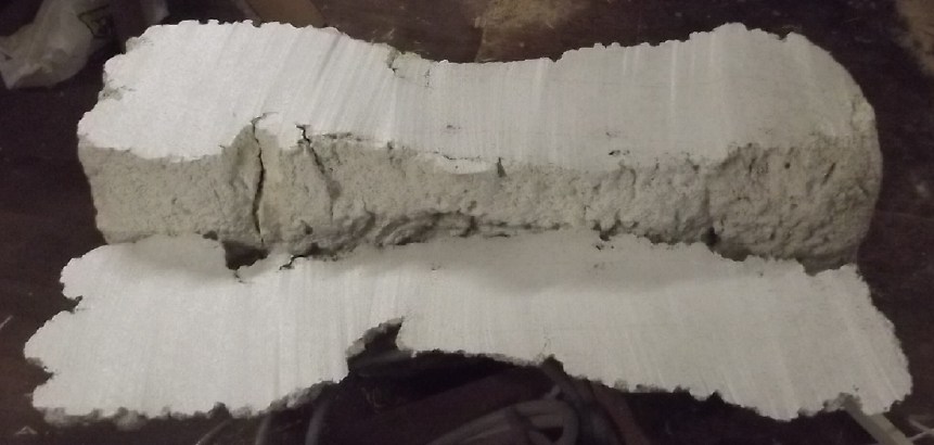 Again cutting it
freehand didn't work well.
Again cutting it
freehand didn't work well.
I had scrounged
a 30 inch wide piece of countertop a while back. I now employed it: I
set it on a work table and turned it
into a hot-wire 'table saw'. or should I call it a "plastic foam
sawmill"?
The wooden arms are C-clamped on the sides and the wire is strung
between them at the desired height/thickness.
One turns on the power and pushes the block of foam through, along the
smooth surface, however fast it wants to go.
3.5 amps seemed good, obtained at about 22 volts.
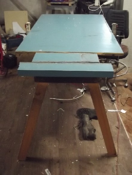
In 10 or 15 minutes: Presto! Four smooth slabs from the big chunk.
[6th] The recycling center was only open
Sunday, Monday and Tuesday. There was little point to driving into town
on a Sunday, so I came back towing the trailer behind the Echo this
Monday. But the big bags of plastic foam were all gone including the
coolers! Rats! I had said I would take them, but I guess he didn't tell
whoever was going to pick them up for disposal.
[15th] I
made a third foam cutting hot-wire saw. This one was
essentially a five foot long copy of the first, with the refinements of
having its own wiring: a 12 foot cord and 36 volt plug, and a switch.
(I figured 36 volts would be about right to get 3+ amps because it was
so long, so it would plug straight in to a 36 V DC wall socket.) I
still
used alligator clips on the ends of the wires to connect to the bolts
with the hot wire, but this time the wire was stapled to the frame.
Someone on youtube had made one with a pushbutton to turn on the power.
I couldn't find a pushbutton. The switch was the next best thing.
It didn't work as well as I had hoped. Being so long, the
wire loosened and sagged upward too much when hot and went within three
inches of the back, so when I tried to cut three inch foam, the back
hit and stopped it just before it finished. It seemed to cut pretty
fast. The current was 3-3/4 amps, just enough to make it glow a bit
if the light was dull. Being hotter it would sag more. Also it wasn't
perfectly balanced and cutting such thick pieces it wasn't very
straight top to bottom.
I had started worrying that
five inches might not be
enough clearance and left some extra wire. Next improvement: I cut
longer
end pieces to hold the wire maybe nine inches from the back, and tuck
them underneath in line with the back so it's more "balanced" and will
tend
more to cut straight down.
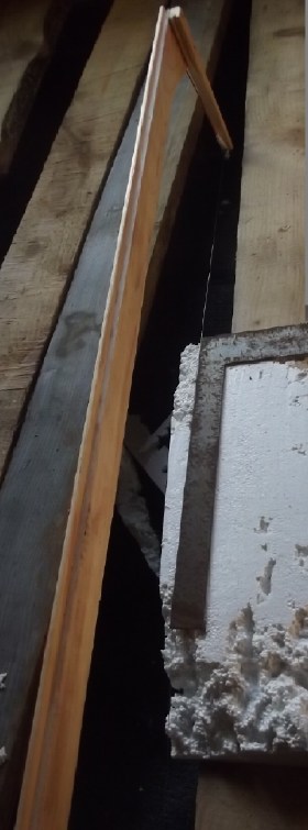 The hot wire 'saws' cut along the whole length of a piece at once. That
melts
just as fast as cutting only a short length.
The hot wire 'saws' cut along the whole length of a piece at once. That
melts
just as fast as cutting only a short length.
I trimmed the sides of a big piece of the beach styrofoam
relatively straight, but when I went to fit it in the wall space it was
already just a bit too narrow. I stuffed in some thin bits to fill the
gap.
I
fitted in three of the four pieces in wide spaces over a window. The
fourth & best piece I'm keeping as a sample for now.
Electricity Storage
My 36V Power Systems: Charging the LiFePO4 Cells
The very flat voltage versus state-of-charge for
lithium-iron phosphate cells makes charging voltage quite critical.
It's best to check with more than one meter and even at more than one
point in the system. Furthermore, there's what is "permissible" versus
what will give longest battery lifespan.
* After I first put the 36V battery system in the house and really
started using them for small electric heaters, one of the (3.2V
LiFePO4) cells dropped to 2.5V and the "balance charger" disconnected
the system to protect it. I thought it was a weak cell and I replaced
it with the spare one I got with the rest. Performance still seemed
disappointing. The cells seemed more like 75 or 100 amp-hours than
nearly 300.
Later I realized it (doubtless) wasn't weak - it was just
that the cell charges weren't balanced and the lowest one had dropped
out first. Soon I had other cells drop out early too. I don't like to
charge to the max, wanting the longest battery life, and the fall and
winter sunlight (clouds) wasn't enough to really top the whole thing up
either. I started measuring each cell after running a heater overnight
and put a power supply at about 3.5 volts on each lowest cell for a few
hours each time. A couple of extra amps for 10 hours adds 20 amp-hours
to the 289 amp-hour cells. It took weeks but gradually they ran heaters
much longer and no cell would drop out early. A couple had higher
readings (power supply on them too long) but they were gradually
evening out and the rest usually read the same to ± a millivolt, no one
lower.
* But there was also a strange discrepancy between the house system and
the cabin system. The cabin would run 250 watts of electric heat for
several hours with a meter saying "39.0" and "38.9" volts for most of
it. Even with a good charge, the house system running 200 watts would
drop hour by hour overnight and could be below 38 volts by morning. Why
were they getting low so fast, and so much faster than the other
virtually "identical" system?
Well, all voltmeters read a little differently - including
the ones in the charge controllers. I raised the target charging
voltage at the house by .3 volts (the minimum change). That pretty much
cured the problem. Voltages still seemed a bit low on other meters.
Finally I looked up charge versus voltage for LiFePO4 and
on one website found 3.6V (rather than 3.5V) is for 100% charge. For a
"36V" system, that would be 43.2V. Several websites gave a table
showing 3.65V per cell for 100% charging voltage, which would
drop to 3.40V at rest - still for 100% charge. Then again
another table said charging them to only 70% daily (3.3V/cell at rest)
would cause them to last 20 years instead of 9, although the suspect
longevity figures for between 100% and 70% only showed one intermediate
step between '9' and '20'.
I want more like 85-90% than 70%, but for longevity and
safety I didn't want to push them to the max. But it seemed the
charging could well be upped a bit more to 3.475V (still under 3.5V)
per cell -- 41.4V in the "36V" system. So I went up another .6V on
both. They'll probably hold closer to their rated capacity, and with
the charging voltage a bit higher they'll charge faster. Now the one
that reads low (cabin) is set to "40.5" and the one that reads a little
high (house) is at "41.7". And they're probably both close to 41.4V or
3.475V/cell.
Some Thoughts
on Storing Energy as Heat
("Dump Loads" and Sand Battery Experiment for February)
[26th] With my unapproved grid
ties removed, the need for alternative
employment of solar power becomes apparent. After mostly dark clouds
through December and earlier January, for two days there has (finally!)
been bright sunshine. I can only run a limited amount of electric heat
at night off the batteries. Once they are recharged during the day much
potential power from the solar panels is going to waste. Turning
heaters on manually in the sunshine just because there is free power
for them would get to be a drag pretty fast, and it mostly doesn't put
the heat where and when it's wanted.
Here's where what is called a "dump load" or loads comes
in. Without
getting into "what?" first, when should a dump load be turned on? One
could say when the batteries are up to a certain voltage. That's not
bad, but it's a fine line if you don't want to have the batteries often
below full even during the day while charging.
Here's another way: Measure the voltage coming from the
solar panels
and see if they're above MPPT. My panels are usually at 60-65V in
sunshine if the battery is under maximum charge. As the battery get
full and
doesn't need as much current, its voltage stays relatively constant,
but the solar panel voltage rises since less is being drawn from them,
indicating they have capacity that isn't being used.
Successive dump loads using more and more power could be
enabled at
(eg) 70, 72 and 74 volts. There would be some hysteresis and maybe a
time delay they so wouldn't flick on and off.
OTOH, to make this work, a wire with the solar panel
voltage or some
division of it would have to be supplied to the appliance's power
control. Unless that control is at the solar/DC electrical panel that
would be an extra wire and not a regular plug - less than convenient.
As to what, turning on space heaters is okay in heating
season,
which is nine months of the year around here. In the cabin, this would
consist of heating up the "sand battery" once that's installed, and
that will doubtless use all the excess solar energy available and
simply mean
less firewood would be needed. But heat is not of much value in the
summer months. Running a car charger as a "dump load" means the car
might not be charged when you need it. It would have to be carefully
watched. Heating water is often a good option. It takes a lot of
energy. But a DHW tank run only as a dump load could run out of hot
water at night. Heating a container of sand to be used as a heat
radiator might be a good option. It need only be a container that can
hold sand and take the heat.
I got another styrene foam cooler and decided to put a
pail of sand
inside as an experiment in February. The plan is it will be placed in
my
bedroom and a coil of resistance wire buried in the sand will turn on
when the solar voltage goes well above the MPP. The insulated box will
hold the sand's heat in. When heat is wanted, the lid will be removed
or left partly ajar.
Copper Oxyhydroxide
or Nickel Oxyhydroxide
or Nickel-Manganese Oxides
& Zincate Cells
(No Report - maybe next winter I'll get back to it.)
My
Solar
Power
System(s)
The Usual Daily/Monthly/Yearly Log
of Solar Power Generated [and grid power consumed]
Notes:
* All times are in PST: clock ~48 minutes ahead of local sun
time, never PDT which is an hour and 48 minutes ahead.
* Unapproved AC/Grid Tied systems have been removed.
* DC meters
accumulate until [before] it loses precision (9.999 WH => 0010
KWH), then are reset - hopefully before that. (Suddenly losing THREE
decimal places of precision is Not helpful!)
* House panels include four old ones on the roof (upper - total rating
~
1000W), two 305W on the roof, three 305W on the south wall below the
roof, and one broken panel mounted verticly on the porch railing (seems
to still work but a lot of shade there).
* Cabin meter is reading LOAD KWH, not SOLAR KWH. These are eventually
the same thing, since the solar charges the batteries for the load, but
not directly indicative of a sunny or cloudy day. (I may put a meter on
the charging some day!)
* Cabin DC includes the three carport panels and the two on a pole in
the yard as well as the four on the cabin roof itself. All nine are
305W.
* The wall, pole and porch panels are easily wiped off from the ground
if it snows.
* Km = Nissan Leaf electric car drove distance, then car was charged.
Car KWH does not add to or subtract from any other readings.
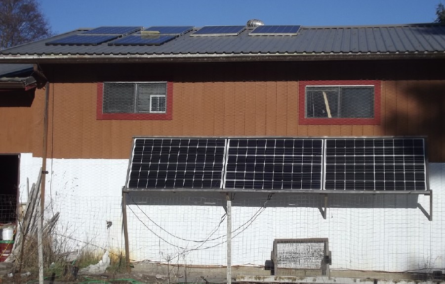
House
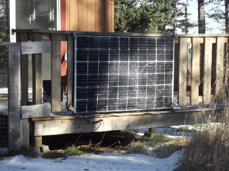
Porch (usually shady)
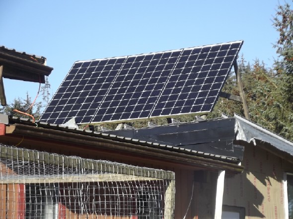
Carport (sunniest place on the whole property)
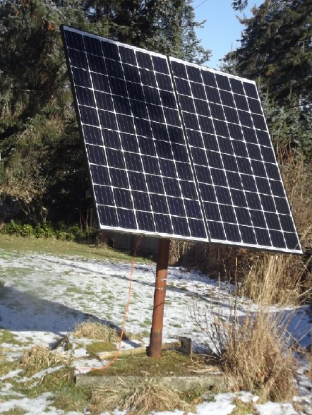
Pole (shadiest place)
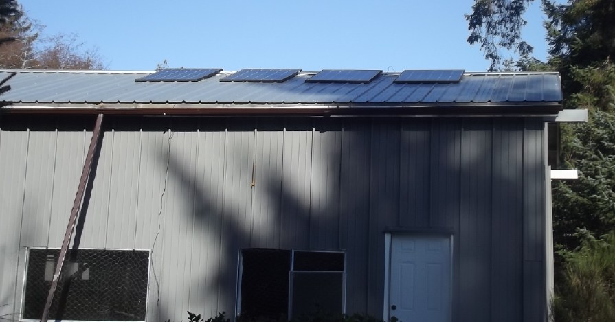
Faraday Cabin (badly shaded in winter)
New Order of Daily Solar Readings (Beginning May 2022):
Date HouseDC, CabinDC => Total KWH Solar [Notable
power Uses (EV); Grid power meter@time] Sky/weather, notes...
December
31st 7.81, 6.99 +> .94 [60Km; 20660@17:00]
January 2025
1st 8.07, 6.99 => .26 [?] Yet more dull, dull days
2d 8.33, 6.99 => .27 [90Km; 20757@20:00]
3rd - - - - - - - - - .29 (est. 1/2 of .59)
4th 8.92, 6.99 => .30 [105Km; 20916@23:00] (est.
other 1/2 of .59)
5th 10.2, 7.19 => 1.48 [20970@17:00]
Unattentive with all the dull days, I didn't think to reset the house
meter. I HATE that it goes from "9999 WH" to " 10
KWH", losing THREE decimal places of precision. It could be anywhere
from 1.08 to 2.07 KWH. Going to "10.00 KWH" would be far more helpful.
6th .33, 7.68 => .82 [21047@17:30]
7th .99, 8.45 => 1.43 [21114@18:00] A bit of sun
8th 2.24, 9.23 => 2.03 [21177@18:00] Some actual sunshine!
Clouds from mid PM.
9th 2.72, .61 => 1.09 [21242@17:00]
10th 4.25, 1.63 => 2.55 [90Km; 21324@18:00]
11th 5.43, 2.21 => 1.76 [60Km; 21347@21:30; 50Km]
12th 7.13, 3.08 => 2.57 [21465@20:30]
13rd 7.93, 4.19 => 1.91 [60Km; 21542@22:00]
14th 8.32, 4.76 => .96 [21592@17:00]
15th 8.58, 5.26 => .86 [21657@17:30] AGAIN clouds, rain,
gloom
16th 1.83, 6.07 => 2.64 [21729@20:00] Sun at last! (Now it's
Freezing out!) Losing some KWH now by not being able to store them!
17th - - - =>
2.30 (est. was bright sunny. We missed a lot because of having no
storage.)
18th 4.22, 6.75 => .77 (est. - cloudy) [110Km; 21870@22:00]
19th 5.52, 7.96 => 2.49 [25Km; 21926@20:30] Cloudy but brighter than
previous gloomy days.
20th 6.39, 8.69 => 1.60 [55Km; 22019@18:30] Mostly cloudy
21th 7.51, 9.39 => 1.82 [22089@18:00] Even the cloudy days are now
seeing over 100W of solar charging.
22d 7.57, .92 => .98 [22157@21:00] Oops, cloudy,
but... The house charging system came unplugged. No wonder it kept
saying "0". (I need to do "click-lock" shells for T-plugs & sockets!
23rd 9.23, 1.73 => 2.39 [22233@18:30]
24th 1.65, 2.41 => 2.03 [85Km; 22322@20:00]
25th 3.79, 3.63 => 3.36 [55Km; 22390@18:30] Full sunshine!
26th 6.02, 4.99 => 3.59 [22459@21:00]
27th 7.24, 5.41 => 2.64 [55Km; ?]
28th 8.38,10.85=> 6.78 [22597@21:00]
(10.85=9.96<reset>+.89<reset again>) Oops, I left the ~230W
of heat on over 24 hours in the cabin! Voltage was still 38.7V at 16:30
PM, but dropped to 37.9 by 20:30. It recovered to 38.3 when I turned
the heat off. (I don't think it ever went down to ~37.3
overnight (of 27th), where the DC power supply would have cut in and
been
taking the load. But it seems it was running out of juice after
supplying 5-1/2 KWH, which probably includes over 1 KWH recharge from
solar during the day - so just 4-1/2 KWH from batteries. See article on battery LiFePO4 charging & voltages
- adjustments were after this.)
29th 10.2*, .68 => 2.50 [22650@17:30] *est. Sunny periods but cabin
battery still recharging.
30th 2.53, 1.59 => 3.44 [22721@18:30] Sunny!
31st 4.62, 3.82 => 4.32 [22796@18:30] More sunny! (& snow!)
February
01st ?.??, 4.44 => .62 [?????] Snow. Cloud. Cold! Solar
panels snowed over. In the PM sometime I swept off the 5 I could reach.
02d 4.95, 4.44 => .33 [22939@19:00] -7°C. All day.
A bit more snow. (.33 KWH at house is over Two days!) I got out a
ladder and swept off a couple on panels on the house roof. Then I
'rebalanced' the four on the ground (that I could sweep snow off of
without a ladder) so two were on the lower section (0-35V) and two on
the upper (35-70V) instead of three:one. The voltages were better
balanced (31:33V instead of 35:26V), but collection only went up from
45W to 55W. Just about no sunlight through the clouds! Why did I
bother? I was sorry I ran 200W of electric heat on the night of the
21st, because with so little recharge there's been barely power for
lights. But it's not Too low unless the dark clouds continue a few more
days. (I prefer the 36VDC lights because they don't have AC electric
fields to worsen my tinnitus.)
03rd 5.75, 4.44 => .80 [23026@18:00] -7° again, still
overcast, windy.
04th 7.77, 5.24 => 2.82 [55Km; 23122@18:30] Still "-"°, but sunny.
05th 2.75, 6.75 => 4.26 [23203@19:00] Still sunny, still fr°zen.
06th 3.95, 7.29 => 1.74 [23278@18:30] Cloudy, but arctic air from
north USA has quit - wind from SE: ~0°.
07th 6.94, 10.2 => 5.90 [23353@18:30] Sun! I ran heaters all day.
('10.2' is a guess. It just said '10', no decimals. I guess I'll have
to reset meters after they hit just '6.000' now, to avoid losing 3
digits precision after '9.999'.)
08th 1.93, 1.87 => 3.80 [105Km; 23422@20:30] part sun
09th 3.49, 3.56 => 3.25 [23484@18:30] cloudy
Chart of daily KWH from solar panels. (Compare January 2025 with December 2024 & with
January 2024.)
Days of
__ KWH
|
January
2025 (18
Collectors, DC/
Batteries only)
|
December 2024
(18 C's)
(Start of No grid ties,
DC/batteries Only)
|
January 2024
(18 C's)
|
0.xx
|
9
|
13
|
14
|
1.xx
|
7
|
15
|
6
|
2.xx
|
10
|
3
|
3
|
3.xx
|
3
|
|
2
|
4.xx
|
1
|
|
2
|
5.xx
|
|
|
1
|
6.xx
|
1 (see 28th)
|
|
2
|
7.xx
|
|
|
1
|
8.xx
|
|
|
|
9.xx
|
|
|
|
10.xx
|
|
|
|
11.xx
|
|
|
|
12.xx
|
|
|
|
13.xx
|
|
|
|
14.xx
|
|
|
|
Total KWH
for month
|
61.32
|
37.13 (batts. only now
& horribly cloudy!) |
68.18
|
Km Driven
on Electricity
|
893.2 Km
~120 KWH
|
919.6 Km
~120 KWH |
1117.8 Km
(160KWH?)
|
Things Noted - January 2025
* [13th] As a month and more rolls by with no daily solar collection
readings of 3 KWH or more, I can't help but think the battery systems
aren't
doing as good a job as the grid tie inverters. And yet, there just
hasn't been much sun.
* The end of the month perked up greatly with ligher clouds and even
some sunshine. As the energy gets much greater, as the sun gets higher
and the days get longer, I need to figure out some way to store or
utilize the energy since I can no longer send it to the power grid.
Otherwise the
panels are partly going to waste. Heating the "sand battery" heat
storage in the cabin should be one good means once all is ready. In the
meantime, I try to turn on small heaters.
* I could make a heater any size I want now with the ni-chrome
resistance wire: my latest hot-wire foam cutting saw shows that about
5-6 feet of it draws 3.5 amps at 40 volts, or 140 watts. I can have any
number of strings in parallel. (Direct heat... or for the sand battery?)
Monthly Summaries: Solar Generated KWH [& Power used
from grid KWH]
As these tables are getting long, I'm not repeating the log of monthly
reports. The reports for the first FIVE full years (March 2019 to
February 2024) may be found in TE
News
#189,
February
2024.
2024
Month: HouseAC + DC +Carport+Cabin[+DC] (from Aug 2024)
Jan KWH: 31.37 + 3.14 + 16.85 + 16.82 = 68.18 [grid
power used:
909; car (very rough estimates): 160*]
Feb KWH: 96.52 + 2.36 + 49.67 + 52.98 = 201.53 [grid: 791; car:
130]
FIVE full Years of solar!
Mar KWH 150.09+ 1.63 + 93.59 + 92.50 = 337.81 [grid:
717; car:
140]
Apr KWH 181.89+35.55 +123.50+142.74 = 483.68
[grid: 575; car: 140]
May KWH 129.23+67.38 +109.6 +126.32 = 432.53
[grid: 405; car: 145]
Jun KWH 152.54+51.02+118.99+141.17 = 463.72
[grid: 420; car: 190]
July KWH 174.22+30.53+111.19+128.62 = 444.56
[grid: 386; car: 165]
Aug KWH 221.99+ 2.63 +142.49+151.67+ 5.78 = 524.56 [grid: 358;
car:
180]
SeptKWH 120.98+ 2.49 + 83.50 + 19.10+ 39.95 = 266.02 [grid: 662
(yowr!); car: 155*]
Oct KWH 78.48+ 7.29 + 64.39 + 7.52 + 40.75 = 198.43
[grid: 711; car: 120*]
Nov KWH 19.63+12.19+ 23.90 + 3.35 + 25.62 =
84.69 [grid: 900 (ACK!);car: 110*]
Now solar is charging
batteries only. 2
systems: house, cabin.
Dec KWH 20.37 + 16.76 = 37.13 [grid: 1866 (using electric
heat!); car: 120*]
Jan KWH 35.02 + 26.3 = 61.32 [grid: 3136 (electric heat
OW!); car: 120*]
* Car consumption comes from solar and or grid: it does not add to
other figures. (Just from grid as of Nov. 18th.)
Annual Totals
1. March 2019-Feb. 2020: 2196.15 KWH Solar [used 7927 KWH
from grid; EV use: -] 10, 11, 12 solar panels
2. March 2020-Feb. 2021: 2069.82 KWH Solar [used 11294 KWH from grid;
EV use: - (More electric heat - BR, Trailer & Perry's RV)] 12 solar
panels
3. March 2021-Feb. 2022: 2063.05 KWH Solar [used 10977 KWH from grid;
EV use ~~1485 KWH] 12 solar panels, 14 near end of year.
4a. March 2022-August 2022: in (the best) 6 months, about 2725 KWH
solar - more than in any previous entire year!
4. March2022-Feb. 2023: 3793.37 KWH Solar [used 12038 KWH from grid; EV
use: ~1583 KWH] 14, 15, 18 solar panels
5. March 2023-Feb. 2024: 3891.35 KWH Solar [used 7914 KWH from power
grid; EV use: ~1515 KWH] 18 solar panels
Money Saved or Earned - @ 12¢ [All BC residential elec. rate] ;
@ 50¢ [2018 cost of diesel fuel to BC Hydro] ; @ 1$ per KWH [actual
total cost to BC Hydro in 2022 according to an employee]; or maybe it's
62 ¢/KWH
[according to BC Hydro at Renewable Energy Symposium Sept. 2024]:
1. 263.42$ ; 1097.58$ ; 2196.15$
2. 248.38$ ; 1034.91$ ; 2069.82$
3. 247.57$ ; 1031.53$ ; 2063.05$
4. 455.20$ ; 1896.69$ ; 3793.37$
5. 466.96$ ; 1945.68$ ; 3891.35$
It can be seen that the benefit to the society as a whole
on Haida Gwaii from solar power installations is much greater than the
cost savings to the individual user of electricity, thanks to the heavy
subsidization of our power owing to the BC government policy of having
the same power rate across the entire province regardless of the cost
of production. And it can be insurance: With some extra equipment and a
battery, sufficient solar can deliver essential power in electrical
outages however long. (Feb 28th 2023: And it's probably well over
1$/KWH by now the way inflation of diesel fuel and other costs is
running.)
It might also be noted that I never went into this in a
big way. Instead of installing a whole palette load of 32 solar panels,
I have 18, and my grid ties aren't the best, and I would be hard put to
give an accurate total of my installation costs. All in all the grid
tied part probably cost me (with all my own 'free' labor) around 7000$.
At the actual "total savings to all" figures, they have paid for
themselves twice over in five years. The 36V DC system largely cost a
couple of thousand dollars for batteries. The solar panels were up. The
charge controller, circuit breakers, DC combo meters [V, A, W, WH], 36V
compatible LED lights and wiring cost were a few hundred dollars at
most. (I did have to make my own T-Plug cables & 3D printed wall
plates.) The battery cost has come down substantially in recent years
and will come down a lot more if I can get cheap, "forever cycle"
batteries working.
http://www.TurquoiseEnergy.com
Haida Gwaii, BC Canada
