Reflecting on recent events: Going to Copenhagen cost the world's leaders $ ??,000,000. And all they did was talk about reducing carbon emissions. Government investment - for example - in the projects of this experienced Canadian inventor, that can dramatically reduce world carbon emissions?: $ 0 (so far). Is this any indication of why solutions are so slow coming?
It is sobering to reflect on how well I was doing working in the civil service at worthwhile but mundane things: there were others to share the load, and the salary just kept flowing in and I could afford within reason whatever I needed or wanted. I bought my house, I could take vacations, and money was put aside towards retirement. Compare that to now: I get nothing and live in want for plugging away alone to the limit of my capacity month after month, and now year after year, at vital things to solve the problems the world's leaders gather together to talk about.
Again, without a Department of Progress in the government to look after public interest in progress and new solutions, such absurd disparities of resource allocation, and a zillion opportunities to improve this, that and everything, go by unseen and unrecognized, while the government pours out R & D money to universities and businesses - but not to inventors, and not into prying open the priceless treasure chest of already invented technologies that are lying around unused, abandoned by events of time and chance, for want of interest or vision, or deliberately killed by vested commercial interests. Seemingly money is poured out in generous measure in every direction except where it will work.
Regrettably improving my torque converter design only went so far this month - one type of play and vibration was replaced by another as I tried to solve the problem. Additional improvements for my design that would be worth trying out came to mind, and I started working on them. Then I decided it would be better to invert the entire arrangement and have the drum also be the motor magnet rotor, driving the plate which would turn with the car wheel. Somehow it just seems to me that that would turn inertia, play and friction more to advantage, working more with it instead of against it. It would also be perhaps 10 pounds lighter overall as the motor rotor and the torque converter drum are one unit instead of two. I started sourcing out parts for the modified unit, some of which will arrive early in February.
One reason I didn't get more done on the torque converter was that I came up with what looks like a fantastic battery 'positrode' chemistry: chelated lanthanum chloride charging to lanthanum perchlorate. Moving 24 electrons instead of one, it calculates out to 5 times more energy per pound than the "Ni" of Ni-Cd, Ni-MH, etc. Couple that with a manganese 'negatrode' for cells of about 2 volts, and it would appear to make possible a battery that could fit in an existing car for 50+ miles electric range without weighing more than an extra passenger or taking up prohibitive space. And it's 'green' and with relatively inexpensive ingredients.
And, I (finally) got some excellent results renewing a lead-acid battery with sodium sulfate salt. I added the salt in October and finally I find the battery much improved... apparently it's cycling, discharging it down to about 8 or 9 volts, that gets them to renew. I also came up with a good theory to explain how it cleans... that the effect is like baking soda (sodium bicarbonate), which is in fact used to clean batteries after draining out the acid, except the sodium bisulfate that forms in the battery from the salt is acidic (pH 1) and can be left in the acid as a permanent electrolyte additive.
It's interesting to consider what a great scam is being perpetrated on all of us. The battery makers sell their deliberately shoddy batteries that only last five years instead of simply adding sulfate salt and selling otherwise identical batteries that would last for 20 or 30. And because they all do it, the public, knowing no better, simply assumes it's the best that can be done. Hurrah for corporate free enterprise!
Now, if only there were three or four of me... I got the washing machine fixed (vital!), so that just leaves the next version torque converter, the new battery chemistry, the car electric heater, the microcrystalline ceramic motor coil cores, the computer program to automate lead-acid battery testing, finishing my long overdue 2008 SR & ED tax stuff (done!)... oh, and cleaning up the house... oh, and... and... let's see... what next?
December In Detail
A quick note on motor types: Informed opinion has it that under a certain size, permanent magnet motors (such as the Electric Hubcap) are best and most efficient, but as size goes up the magnet costs get higher and induction motors get more efficient. The switching point is thought to be around 5 KW. If the EH draws 120 amps peak at 36 volts, that's 4320 watts (5.8 HP), so it's in the "PM is best" range. A larger motor, ie 10 to 20 HP such as seems to be needed to operate a car through a regular automotive transmission, evidently might as well be an induction motor.
But this doesn't consider the need for a 'pancake' shape motor for the outside of a car wheel. A pancake shaped axial flux induction motor could doubtless be designed, but there isn't one now, and since it's below the size break (if only by a little), it doesn't seem worthwhile designing one.
I didn't get at the heater project in January except to buy a 12 volts DC fan and a switch. The dual 25 amp On-Off-On toggle switch was the most expensive single item in the entire project (so far, anyway). I gave up on the idea of using the heater's existing 120 VAC fan and the original housing, and to just use its heat coils and some of its electrical parts, in a custom housing. The parts are all sitting in a box.
I did do a little shopping to source out an axle and bearings idea.
I went into a store and looked at some packages of trailer wheel bearings. Just to play with ideas, I bought a package of 1" bearings with two bearings and the outer races for them (along with a cotter pin, seal, cap and a little grease packet). These appear to be identical to the 1-1/16" bearings except the inner race is thicker, making the center hole a bit smaller. The outer races are identical, so they fit the same wheel hubs. (...and yet the store's price was $22, versus $32 for 1-1/16"!)
My thought was that a one inch bolt (or one inch threaded rod) is an easy thing to buy as an axle, in any length. So here we have ready made axles and bearings for Electric Hubcap systems. A nut(s), spacers of 1" steel pipe, and the bearings can be placed anywhere along the bolt shaft to give any desired spacings. Of course, a hole will have to be drilled for a cotter pin to ensure the nut can never turn. (Or perhaps a hole can be threaded into the nut for a set screw. In that case, a flat spot or indent should probably be filed or ground into the axle where the set screw hits. You can tell where it hits if you do it up tight and it roughs up the axle's threads.)
1" trailer bearings on a 1" bolt "axle".
Above it, a 2" pipe coupling that could be turned to make part of a hub. (shown with a bearing stuck into the end.)
That just leaves hubs. Buying ready made trailer hubs and using a car brake rotor is still a simple option.
1" bearings on 1" bolt 'axle' with trailer hub.
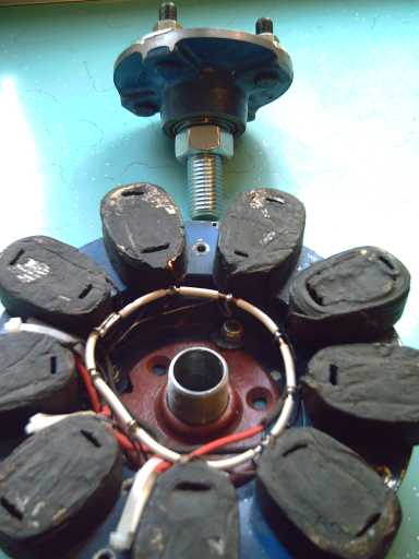
Pipe "floor flange", here in previous motor, with a pipe 'close nipple' fitting, could affix the axle to the motor stator.
(Then the nipple/flange actually looked like a good part for the torque converter rotor.)
Something I'd like to try is to take a 3/8" or 1/2" thick steel disk and turn the center so that the outer bearing races just go in 1/8" each, and see if that would be stiff enough, or if some sort of hub to space the bearings much farther apart is actually necessary to keep the disk from wobbling. Everything would be so much easier if one could simply use a single piece flat disk. (It seems quite unfortunate that the holes in the center of brake rotor disks are all too large to use them as hubs.)
Should the length of hub be needed, I found an inside threaded pipe coupling about the right size to fit. The ends would be turned to make sockets for the bearing races, and an outside end would be turned to fit the rotor. (This might make it rather thin at that end?) Welding the disk to this piece might be required. (Or maybe make the fit 'perfect' for pounding them together? Or?...)
(Sigh... looks like all these details change again with the new torque converter design, which uses a brake drum rather than a brake disk for the magnet rotor.)
Mechanical Torque
Converter Project:
Torque Leverage Without Gears
January Details
Torque Leverage Without Gears
January Details
The torque converter has proven more challenging - and baffling - than I expected. I've re-thought the design several times and changed it from magnetic to purely mechanical. It looks like I'll be rebuilding it once again. This time, however, the design is getting narrowed down. The same brake drum (except a new one that isn't so hacked up) will be used in the same way, but the layout will be inverted. The drum will be the motor rotor, with the magnets on the outer face facing the coils, and the hollow end complete with bevel tracks will face the wheel. The inertia rotor will be driven by this instead of the other way around. I think this arrangement should should provide a bigger inertial "hammer" to drive the wheel, and a bigger hammer drives nails more easily. The motor will get less 'shock' with each torque pulse it supplies.
The inertia plate/rotor will also be mounted on the center axle. This more solid centering system should eliminate a lot of vibration and keep it aligned. I've found that a "one inch" steel pipe coupling is a perfect fit over the 1-1/16" trailer axle, and will freely slide up and down it with the inertia plate. (A specially machined sleeve could hardly be a better fit!) A pipe "floor flange" will mount the close coupling onto the center of the plate, or if I have to make a new plate anyway (might have to), I can have the center hole drilled and threaded to fit it directly. This time, the connection link pins go between the inertia plate and the car wheel, or a plate mounted on the wheel.
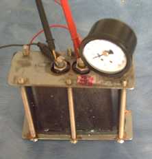
So, viz: the axle, with the stator (coils) bolted to its flange as the outer end, then the spinning drum bolted to the cut-down trailer hub with bearings (with supermagnets facing the coils), and then the inertia plate, sliding in and out inside the drum in accord with the spinning bevels, pushing on and rotating with the car wheel via the link pins. (The nut on the end of the axle will keep the inertia plate from coming off the end, eliminating the need for a big retaining ring inside the lip of the drum.)
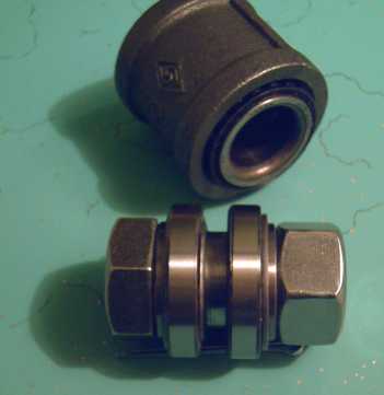
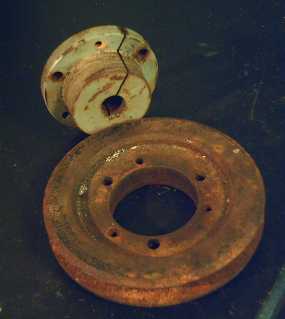
The essence of the new configuration. Behind is the replacement drum. On top (standing on end loose) are the link pins to the car wheel. I think they should be mounted farther out than the lug bolt position.
(A picture showing the red sliding flange/nipple piece better is above. A better part might be the compression flange shown a ways below.)
Mechanical Torque Converters are better in every way than automotive transmissions, but since they save a lot of fuel, they have for 85 years run up against the brick wall of the big car companies, which take their orders from "big oil". "Big oil" doesn't like anything that saves fuel, regardless of the wishes of the rest of the world. A torque converter made as part of an add-on car motor system that can be made even in small shops anywhere alters the commercial picture at a basic level.
After the failures of the trials in December, and noting that the unit was very noisy, I started thinking of big changes to the design, and came up with a few ideas. But were they really any better?
I thought of the vibration of the motor, and thought, well, there's no axle, but not only that, the four driving pins have around 1/8" of free play. Owing to the imperfections of a hand-made unit, plus the play, the four pins wouldn't all hit exactly simultaneously, and the force developed by one pin without counterbalance would lead to vibration, exactly as seen, instead of thrust. If all four pins were virtually in contact with the rim, there'd be much less free space to vibrate in. I decided I'd give the current design another try thus set up.
But to combat the noise, I thought, what if the bevel the pins strike was ground out so that they'd first contact almost parallel, and then the slope gradually increased to the 45 degree bevel angle? Then instead of hitting with a bang like a hammer, they'd make a smooth change in direction. This should also reduce vibration. So I "hollow ground" the forward bevels to at least partly attain the desired slopes. I left the reverse ones at a flat 45 degrees, so forward and reverse should show the contrast between new and old. The end stops are still flat and will cause noise, but they are less important and can be dealt with later if the design works.
With the curves, the redirecting of the inertia plate from simply turning to making a 45 degree sideways motion as it turns happens over a length of about 3mm in the curved "hollow ground" ramps, and it's about 85mm between each 'left' and 'right' turn. So we get thrust for (3 / 85 = ) 3.5% of the distance, or the inverse, the torque within those 3mm thrust zones (ignoring losses) is 28.3 times what it would be averaged out over the 85mm.
Theoretically the thrust magnification with the pinpoint bevel hits should be 'infinite', but obviously the losses were so high in December that the car didn't even move.
Would my small changes turn failure into success? Testing said "nope"! The motor vibrated, more symmetrically but in and out, rather than the inertia plate sliding freely on the pins. The principle was there, but the mechanics would have to be more perfected, and it was still quite noisy. Back to the drawing board?
As with the motor suspension, it appears I overlooked something earlier as I skimmed by it... going back over clock escapements, I noticed the first modern type, the "anchor" escapement, invented about 1660 by Robert Hooke, noted scientific revolutionist, technologist and inventor. Hooke, BTW, I'd never heard of, but he has an utterly dazzling array of accomplishments to his credit. A good number of things things that we now know and take for granted were first discovered by him. Just for example, the "father of microscopy" coined the term "cell" to describe the basic unit of life. (This was later merged with "picture" to create the term "picture-cell" or "pixel", the basic unit of video display... once plainly visible but now microscopic.)
Hooke's mechanism had a wheel of gears and a back-and-forth pivoting "anchor":

Anchor Clock Escapement
(escaped in good time from Ancor Wat?)
If the geared rotor is turning as shown, it pushes the right Hooke to the right until it's clear of the gears. In doing that, it pushes the left Hooke into the gears, between two teeth. Just at or soon after the time the right... cam?... is clear, the next tooth starts pushing on the left cam. This brings the right... cusp?... back in between the gears and so on. The two cusps are never both clear of the gears at the same time. At low speed, moving the anchor back and forth is all but effortless, but the anchor has weight (and here I thought it was named for the shape!), and the faster the rotor turns, the faster the anchor fights its own inertia to move back and forth. With a clock pendulum (giving the anchor shape), the timing is regulated. Forcing the rotor, the resistance to the turning rotor rapidly increases with the square of the speeds. (I remember trying to turn a clock faster than it wanted to go when I was a kid (though not why). It took a lot of push, and there was an energetic "zzzzzzzzzzzzzz" and parts flying around too fast to see. Remember those mechanical bedroom alarm clocks for $4.99 in the 1960's, that had to be wound up all the time and only lasted a couple of years?)
Unnoticed in all this is that all the force generated would be pushing the pivot pin of the anchor to the left. If instead of being mounted on a fixed piece of a clock, the anchor is mounted on... say... a torque converter output rotor, that rotor will want to turn to the left. The faster the motor turns, the harder it will want to turn with it, and the only losses are frictional and (ahem) vibration, so if the motor is turning a good speed, the output force (torque) can be stronger than the motor's, probably by a very good ratio. (The vibration should be small compared to my previous design. And it will be much quieter.)
Now it just needs to be redesigned so everything fits the motor and rotor drum, make it symmetrical so it will run either direction, and put some "anchor" structures around the rim.
What to use for the geared wheel? For fine gears, a car flywheel gear might do. But the gears as shown are rather coarse. For fine gears, the anchors will be buzzing in a frenzy. What about using a brake rotor with fins - both for the fins as coarse gear teeth and as the magnet rotor for the motor?
But then again, what is so fundamentally different between this and my design? They both use inertial weights moving back and forth as the motor turns. According to clockmakers, the angle of highest energy transfer efficiency is supposed to be 45 degrees, but my inertia plate is going way faster than a clock. It wallops those 45 degree bevels awfully hard, creating that vibration and noise and in fact preventing the motor from revving up to the desired extent. Furthermore, there's nothing keeping the plate true except inertia, and friction with the pins must be what causes the motor to vibrate in and out. If these details could be sorted out, it could make all the difference.
I stepped back a bit and thought mine still looked like the simplest design with its one moving part, so I decided to stick with it and try to modify it to solve the various problems that testing had revealed.
First (and easiest) I decided to try grinding my bevels down to 23 degrees instead of 45. I can curve that to reduce noise, and I can try even less angle if that seems to help. After all, a 28 to one "gear ratio" is much more than is actually required. 10 to 1 is often used for electric propulsion, and the Electric Hubcap is a high torque motor to start with, so even around 6 or 7 to one is probably sufficient. That would greatly reduce the vibration and noise, so hopefully that would mean more energy going into wheel rotation.
Second, and also easily done, I disassembled the motor and removed the drive link pins. I had recognized that they would have to be tapered to prevent binding when the motor went up or down over a bump, and I had ground in the tapers. But whereas they had started smooth and straight, now they were tapered but rough ground. A lot of friction would explain the motor vibrating in and out with the torque plate. I sanded them with #80, 220 and then #600 sandpaper, and then polished them on a polishing wheel on the wood lathe with polishing compound.
Shallower bevels in the rim (forward direction only - so far, reverse is still steep) and the slightly tapered drive link pins; one inserted, one fine sanded, and two polished.
(I should have saved a rough ground pin for the picture!)
The third item, the inertia plate having no axle to keep it true and in line, could evidently only be solved by making an axle. This looked like a considerable challenge. I started playing with parts and came back to my previous motor that moved the car in October 2008. It had some steel plumbing pipe fittings, including a "floor plate" flange with a threaded center hole to hold it all on the rotor.
Somewhere in there I started to think in terms of reversing the whole unit so the inertia plate would go on the same axle as the stator and rotor.
I went out and got a one inch "Close Nipple" that fit into the floor flange, and (after filing out some interior "burrs") it actually proved to be a perfect fit over the 1-1/8 inch trailer axle, sliding back and forth freely but with little sideways play... just what would be needed to hold the inertia plate centered and straight, which could by itself solve most of the vibration and alignment problems.
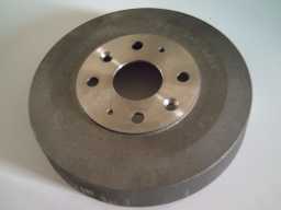
Lastly, I had ground off the center hub of the drum rotor so I could bolt the wheel onto the car with the drum attached. Reversing the drum meant it needed that center again to mount it on the axle hub. Either I had to weld it back on with questionable prospects of getting it on secure, straight and centered, or I had to buy a new hub. I hate welding, so that decided it.
Finding a new one proved to be more difficult than expected - It took all afternoon to find and order the right one, and then a trip to pick it up the next morning. I didn't see one, or anything much like it, at a big auto wreckers. When I pulled that drum out of a garbage can at a brake shop with no idea why except that it looked potentially useful for something, and little did I know it was the only brake drum anything like that size and shape, and that it fit only a few 1990-1992 cars.
However, finally one the auto parts stores had a big "Raybestos" catalog with every drum indexed by diameter, and some specs and a picture of each one. I found it in there, their model 2767R. It appears to be by far the best drum, if not the only suitable one.
One other type of drum is trailer brake drums (used with electric trailer brakes, eg Dexter) with built-in bearing hubs - potentially a one-piece solution. But when viewed, the outer faces proved to be very convoluted where a flat surface is needed to mount the magnets on.
The Raybestos replacement drum also proved to be inferior on the outer face to the original Ford drum: the original drum's outer face was flat except for a diagonal bevel around the outer rim, 7/16" wide. The magnets are 2" long, so 7/16" at the outer end in the air unglued is tolerable. The replacement, however, has just one difference to the original: its bevel is 1-1/8" wide, leaving less than half the magnet to glue down. I'll have to turn that outer face down flat on the lathe - Yuk! Or put in little wedges under the magnets. Now I've finally tracked down the cars they were used on in case I do another one, in hopes some auto wrecker may have the original Ford or Mazda part:
Professional Grade Brake Drum (Raybestos - 2767R, B000IYJI38, R422767R)
Fits these Vehicles:
- 1991-1992 Ford Escort
- 1990-1991 Mazda 323 ("Competing" auto companies from different
countries? Hah!)
- 1990-1991 Mazda Protege
- 1991-1992 Mercury Tracer.
The Raybestos catalog also had a complete line of disk brake rotors, and I found a couple more suitable (...for magnet rotors...) than anything I've managed to find previously. It appears these particular models are no longer in production, but I saw some others about 10" diameter, still fine for making the motor stators and better than what I have now. (...evidently I'm having trouble with the mental leap that the magnet rotors will now be drums rather than disks.)
Why on Earth didn't they show me that catalog over a year ago when I came looking for a specific size of disk brake rotor? They told me then that the parts were all indexed only by make and model of car. I guess that would have just made life too simple! ...Then again, I'd never have been searching brake shop garbage bins and I wouldn't have found the brake drum that I eventually used for the torque converter, and I wouldn't have thought of using a brake drum at all if it hadn't been sitting there on my shelf. Obviously it's a few notches above the aluminum frying pan I started with. ...I guess that makes it providence!
I went out to get a shaft collar to hold the drum rotor bearings, now at the stator end of the axle with the sliding inertia plate flange beyond, preventing simply putting in a spacer to where the nut sits. I feared it might be impossible to find for a 1-1/16" shaft, and while indeed no one had anything on the shelf, Smith Bros. can order things for that size shaft. Then I looked at their compression flanges for pulleys, etc, and it turns out they can get those in 1-1/16" size too. If I simply don't compress it, this will be a much more solid sliding flange for the inertia plate.
Pulley with (5/8") compression flange.
The similar flange with 1-1/16" I.D. should make a great center for the inertia plate rotor.
(It even has a screw to adjust the amount of compression for a perfect sliding fit on the axle!)
The shaft collar and flange should be in next week, but that'll be February.
January Details
The Short Version: It's the Holy Grail !
The exciting promise of the perchlorate/chloride positive electrode electrochemistry, described below with a manganese (Mn/Mn(OH)2) negative, is for a small, safe, economical battery of great power and energy density, with long and perhaps indefinite cycle life, the "holy grail" of battery research.
Oxidizing chloride to perchlorate moves eight electrons per molecule instead of one or two. (In fact with three chlorines, LaCl3 to La(ClO4)3 moves 24.) The chlorate to perchlorate reaction squirrels away oodles of oxygen to 'oxidize' the positive electrode.
Manganese has the best looking negative reaction voltages of any element, and in a lightweight atom, providing substantially more energy than all the similar reversible reactions - Fe, Cd, MH and Zn.
The combo should make a small, light battery that could power a hybrid car for a good distance. It looks very doable, yet it appears neither perchlorate positives nor manganese negatives have been previously explored for battery use.
Of course I'm not patenting it. I'm publishing it here for anyone to use, along with all the other things I've worked out over two years to simplify and improve battery making.
| Battery Type |
Energy Density W-H/Kg |
Power Density current/area |
| Pb-H2SO4 | 30-40 | high (disch.) low (charge) |
| Ni-Fe, Ni-Cd | 20-50 |
lower (Fe) higher (Cd) |
| Ni-MH | 50-150* | higher |
| Lithiums | 70-150 | lower |
| 'X'ClO4-Mn | 250-800** | probably high |
** 250 W-H/Kg is based (pessimistically) on 1/10 of the total battery weight being active chemicals, while 800 is (optimistically) for 1/3. The figure for the charged electrode substances themselves is around 2400 W-H/Kg.
At first I had what I thought was a great scheme for using KClO4 (insoluble)/KCl (soluble) both as electrolyte and positive electrode chemical. But the soluble intermediate products formed between chloride and perchlorate would no doubt have caused problems, which means it has to be done differently. So lanthanum chloride/perchlorate is used instead, which stays chelated in the positive electrode gel in any state of charge, and the electrolyte is separate. The chelating gel is a key feature, and I have devised about four separate ways of trapping heavier atom cations (like La+++), which may be tried together or separately.
I looked over a 'paper', Making Potassium Perchlorate, about converting KCl to KClO4, by an anonymous author (or at least unnamed anywhere I could find). At the same time, I was considering the Poggendorff cell (KCr2O7-Zn-H2SO4) and a KMnO4-Al-KOH non-rechargeable cell I read about (of great energy density). Thus thinking of dichromate, permanganate, and perchlorate oxidizers, I began to recognize some common workings. In the dichromate and permanganate batteries, the positive electrode 'stuff' exists as a dissolved salt. In the permanganate battery, the reactions are given as:
ANODE: Al + 4OH- ➝ Al(OH)4- + 3e- , E° = -2.34V
CATHODE: MnO4- + 2H2O + 3e- ➝ MnO2 + 4OH- , E° = 0.60V (4)
OVERALL BATTERY: Al + MnO4- + 2H2O ➝ Al(OH)4- + MnO2 , Ecell = 2.94V
Such a high voltage in an aqueous cell has serious self discharge problems, and it can't be recharged. Also the liquid electrode chemical will gradually touch the other electrode, a bit at a time, and likewise discharge the cell. (The permanganate/aluminum one by the US Navy is basically for torpedos or whatever, where all the energy is to be used up in a short time -- the liquid is added just before launch and the battery immediately starts discharging whether it's used or not. With the 2 volt dichromate cell, the zinc electrode was pulled out of the liquid when the battery wasn't in use to save it from discharge and dissolving.) But simply giving the above cathode reaction finally explained a missing piece of puzzle for me. The reaction KCl <=> KClO4 seemed unique, not because the chemistry is so different but because while potassium chloride salt dissolves, potassium perchlorate is virtually insoluble in water. For this reason it appears it could make a rather unique combination electrolyte and positive electrode active chemical. The theory was:
1. KCl is the discharged state. KClO4 is the positively charged ("oxidized") state.
2. As the battery charges, KCl is converted to KClO4 at the positive electrode.
3. KCl is fairly soluble (~~300g/L), so the electrolyte is dissolved and diffuses freely. Since KClO4 has very low solubility (~~15 g/L), it will crystalize out around the positive electrode.
Potentially, one could have a KCl saturated solution plus a "reservoir" of undissolved KCl salt lying on the bottom of the battery. As the battery charges and KCl is converted to solid KClO4, KCl from the bottom will dissolve to replace it, keeping the electrolyte at full strength. As it discharges, excess salt settles out. This way, way less water will be needed to hold sufficient salt. Of course, for this to work, "saturated" would have to be a good workable electrolyte strength. In fact, this would seem to be just about right, but it's very possible be that a weaker concentration will prove preferable -- the author indicates that a high KCl concentration may tend to create chlorate rather than perchlorate. Then again, if a potassium chlorate molecule does come out of solution in contact with the electrode 'sponge', it is still amenable to being further charged to perchlorate, so it may all end up as perchlorate in the battery's environment regardless. A further issue is that water is used up during discharge, so there needs to be sufficient excess water in the charged state to allow for that.
4. The positive electrode needs to be a conductive, porous matrix to hold lots of KClO4 crystals. (We can do that - it's not the topic here.) Thus the positive electrode 'sponge' will gradually saturate with KClO4 as it charges, which will turn into KCl and dissolve as it discharges.
5. If the reactions are more alkaline, we expect (charged <=> discharged):
KClO4(s) + 4 H2O + 8e- <=> KCl(aq) + 8 OH- [~+0.6 V ?]
4 Mn(s) + 8 OH- <=> 4 Mn(OH)2(s) + 8e- [-1.56 V]
6. If, on the other hand, the reactions are more acidic:
KClO4 + 8 H+ + 8e- <=> KCl + 4 H2O [~+1 V ?]
4 Mn + 4 H2O + 8e- <=> MnO + 8H+ [-1.18 V]
(Hopefully not acidic enough to dissolve MnO?)
7. Either way, cell voltage will be around 2 volts. This does well for energy density compared to Ni-MH, etc, at 1.2 volts.
8. If I have these balanced right, 8 electrons per reaction at the positive electrode looks like much higher energy density than one electron with nickel, manganese, etc. positives.
9. As the positive electrode material is in solution, hopefully it will have an extremely high conductivity, as is the case for the KMnO4-Al battery: amps per square centimeter (sc). Mn and its oxides/hydroxides are more conductive than most. Thus we might see an amp per square centimeter power potential, or at least hundreds of milliamps (and without too much pricey monel!), instead of 50 mA or so for typical Ni-MH etc.
10. We need to enable the KCl => KClO4 reaction to occur efficiently in the battery, with other substances. Making Potassium Perchlorate seems to hold some good ideas and much promise that this will work, as he in fact makes it directly by electrical oxidation of KCl as the battery is supposed to do, with a 'tincture' of KCr2O7 and a bit of NaCl in the mix, and we might try a bit of KMnO4 instead or in addition. (He thinks the NaCl could be dispensed with, which would be agreeable.)
11. Any of the slightly soluble KClO4 that gets to the negative electrode will be reduced to KCl during charging and dissolve, so any gradual migration will do no damage. And there should be no gradual changes to the positive electrode from the charge-discharge chemical reactions.
12. Even so, gradual migration can be limited or eliminated by using microporous separator sheets to block the larger perchlorate ions, eg cellophane. (NON PLASTICIZED cellophane!!)
13. Since the positive electrode chemical dissolves as it discharges, it leaves vacant spaces behind for electrolyte to fill, and so the positive electrode 'sponge' can be made any thickness at all, perhaps even 1/2 an inch. Current capacity and voltage will be undiminished over the discharge-charge cycle. As the battery charges and discharges active KClO4 is always in good contact with the electrolyte and the conductive electrode.
IF it could be made to work, which seemed likely, this should make a wholly better battery than anything out there, in accordance with one of my main original objectives in taking on this project. It could go in a car outfitted with an Electric Hubcap motor without taking up a trunkfull of space and adding the weight of 3 or 4 passengers to an empty car. (Another main objective was, since I didn't initially know too much about battery workings, to come in and find a fresh perspective, and in my ignorance of convention stumble over a better battery design or chemistry. Seems that part of the objective has only happened after a lot of study and experimenting, and only with a significant diminution of ignorance!)
Atomic weights:
H - 1
O - 16
K - 39
Cl - 35.5
Mn - 55
La - 139
Hence, molecular weights:
KCl - 74.5 (the electrolyte)
LaCl3 - 245.5
La(ClO4)3 - 437.5
Mn(OH)2 - 89
The math (Awg, not math!):
* A mole of KClO4 (chemistry 1) weighs 138.5g.
* 1/138.5 moles/gram * 8 moles of electrons/mole * 96500 coulombs/mole of electrons = 5574 coulombs (amp-seconds, A-S)/gram
* 5574 A-S/gram / 3600 seconds/hour = 1.548 amp-hours/gram --- WOW!
* A mole of La(ClO4)3 (chemistry 2) is 437.5 g, and the A-H works out to 1.470 A-H/g
By contrast, Ni(OH)2 is .289 AH/g - 1/5 as much, so this eliminates 4/5 of the weight (and perhaps a similar volume ratio, 4/5?) of the positive electrode's active material. And of course something like 4/5 of the monel etc. I think it's safe to say that the chloride<=>perchlorate chemistry appears to be much better than the best known battery chemistry now in use.
At the other electrode, barring some unknown better chemistry or some unexpected problem with having a manganese negative (when MnO2 is the most common positive electrode around), Mn/Mn(OH)2 appears to be the best possible rechargeable aqueous negative electrode, as noted in a previous TE News. It's 1/55 moles/gram * 2 e-'s/mole * 96500 AS / 3600 S/H = .975 AH/g, or one amp-hour per gram after adding the sales tax. This is practically as good as the best metal hydrides I've heard of, and with the higher voltage, it should store around 1.75 times the energy. It's also a little better A-H than zinc, and the voltage is a little higher, so (using published alkaline solution voltages): (.975 AH/g (Mn) / .820 AH/g (Zn) ) * (1.56 v (Mn) / 1.28 v (Zn) ) = 1.45 times more energy per weight than zinc.
The exact relative volume of this electrode is more uncertain, as it depends on the volume of Mn(OH)2 compared to other hydroxides or chemistries.
After thinking about the above a while, I started to see a potential problem. Might the Cl- not pick up one oxygen atom at a time and go through the sequence:
KCl - salt
KClO - to hypochlorite 'bleach' [0.9v]
KClO2 - to chlorite [0.59v]
KClO3 - to chlorate [0.35v]
KClO4 - to perchlorate, the final product [0.17v]?
The trouble is that the bleach, for example, would still be soluble, and small enough to pass through the microporous separator. Doubtless some would drift over. Then it would go discharge the negative electrode. And during discharge, it would drift off from the positive electrode without finishing being discharged.
This doesn't make the idea of Cl/ClO4 a bad one, but it does mean it needs to be done a different way. For example, with lanthanum chloride/perchlorate: LaCl3/La(ClO4)3. The chloride-perchlorate reactions would be pretty much the same, but the intermediate products won't migrate. The heavy lanthanum ion, chelated in a gel, eg, my fired bean sauce/monel/lanthanum mix and-or the veegum/CMCgum mix and-or the agar, and finally with the zirconium ion shield, should remain stationary in the electrode matrix, an "anchor" with its 3 chlorines absorbing and releasing O--'s. Fixing the lanthanum in place was part of the original idea of this mix. (Its trigonal structure evidently is the same solid or dissolved: "The close agreement between the EXAFS spectra of solid nonaaqualanthanum(III) trifluoromethanesulfonate and of an aqueous lanthanum(III) perchlorate solution shows that the hydrated lanthanum(III) ion in aqueous solution most probably has the same structure as in the solid, i.e., nine water molecules coordinated in a tricapped trigonal prismatic configuration.")
The process for making LaCl3? You guessed it! - add hydrochloric acid to lanthanum hydroxide. It works out to 1470 A-H/Kg, just slightly less than the potassium version.
The reader may have noted above the different voltages of the reactions, with hypochlorite to chloride being the most reactive and perchlorate to chlorate the least. This is backwards to the usual case. If a molecule is going to charge or discharge (electrochemically), it looks to me like it will pass rapidly through all the intervening states and end up as chloride or perchlorate, because of this "positive feedback" loop. There are some (to me at least) unknowns here... what will the actual positive component of the voltage be? In the permanganate battery, it was .6 volts. Doubtless in making permanganate into manganate and then into manganese dioxide, two different reaction voltages occur too, but the patent simply said "+0.6 volts". I'm going to guess that it will all average out to one figure, but one is left with the thought that the 100% charged battery voltage may read the .15 volts perchlorate voltage (on top of whatever the negative side is), but as soon as discharge starts it will jump up to the hypochlorite level, .9 volts (+ the negative side). I somehow doubt that will happen.
Copper (or some other lighter element) with chlorine might make a good electrolyte. Like most chlorides, CuCl2 is soluble in water, and there's also CuCl: the copper can easily lose or gain one chlorine at a time. (Though if the reaction is Cl- <==> ClO-, that's probably of no consequence.) And it's green, the correct color for green energy. Copper isn't much heavier than potassium and it holds two chlorines instead of one so it works out a bit lighter. (Unless it's just heavy enough to chelate into the gel, in which case it could be used instead of lanthanum. This seems unlikely.)
Ingredients used in the manganese 'negatrode' were: #300- Mn powder 7.5g; MnO2 9.5g; #300- monel powder 7.7g; Sb4O6 (AKA Sb2O3) .08g; veegum .6g; CMCgum .3g; Sunlight lemon fresh dishsoap .5g; 40% ethanol in H2O (AKA Alberta 'triple distilled' vodka) 2.25g.
The mix may have been a little on the dry side. There was no sign of any squeezed out moisture in the compactor. I had meant to add 1.5g of Sunlight - misread my light pencil marks. As long as it holds together until it's installed, it should be fine.
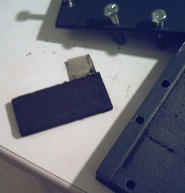
The manganese 'negatrode' briquette, fresh from the compactor.
The powder filled the compactor to the top and made a 6mm thick compacted electrode theoretically good for over 13 amp-hours. It weighs 34 grams all up, so theoretically it's good for about 400 A-H/Kg. If there was nothing else to add, that would be great! As I didn't use agar this time, there's no need to steam it or otherwise process it before putting it into the battery. And of course I'm certainly NOT going to add HCl to affect the organics. (Makes MnCl - See TE News #21.) The jelling will have to be accomplished by electrochemical means - charging - once everything's assembled and (otherwise) ready.
It will take some experimentation to see whether the monel is needed or not, or how much (if any) is useful. I probably should have added more to ensure great conductivity, but 'charged' manganese is also conductive metal.
I added four more more bolts to the compactor before I did the positrode, to help ensure the best briquette compaction. After all, without good compaction, maximum current flow is poor to nil and the briquettes will be the more prone to falling apart.
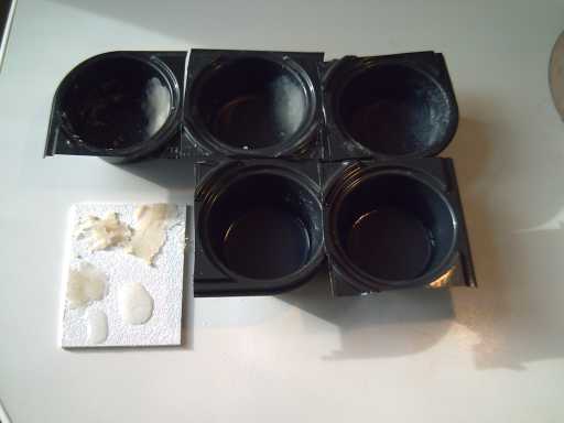
The ingredients were: 8g of the fried monel/Lanthanum/bean sauce (thiamin mononitrate) mix detailed in a previous newsletter, 4.5g of La(OH)3, .14g KMnO4, .16g KCr2O7, .6g veegum, .4g CMC gum, 1.0g Sunlight dishsoap, and 3.0g 40% solution CH3CH2OH (AKA Ethanol, AKA Alberta Vodka).
The resulting mix was too damp, so next time I'll try 3/4g Sunlight and 2.25g CH3CH2OH. The 'trode was about 3.5mm thick.
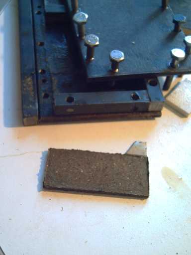
Compacted La(ClO4)3 'Positrode' briquette
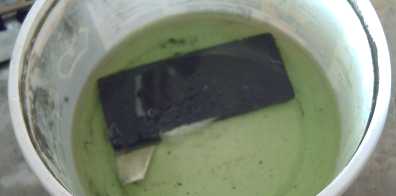
Positrode with the La(OH)3 turning to LaCl3 in HCl acid.
Having used the veegum and CMCgum as electrode gel, I decided the thing to do next was to put a coating of agar over the entire electrode. Agar has been used to make salt bridges (as well as aspic, jelly deserts, bacterial growth media for microscope slides...). It's a valuable way to separate the 'positrode' from the 'negatrode'.
As a first step, I experimented with proportions. I was going to try a gram of agar in 5g of water, but I got it up to .7g of agar and it had soaked up all the water and looked way too thick. So I tried, in 5g of water: .7g, .5g, .25g, .12g and .07g of agar. I put the ingredients in cut-apart plastic muffin trays, and heated them in a pot of boiling water on the stove. Then I cooled them in the fridge. I poured little samples onto a piece of plastic.
The first three were more of a paste than a gel, and weren't really coherent, except for a good gel layer on the bottom of each tray.
The pastes could be sculpted into any shape. The gels could be squished with only a little finger pressure, but up to that point they were resilient and would hold their shape.
Of the last two that were good gels, I had the vague impression that the last was slightly stiffer, contrary to expectation. So I did another one with only 4g of agar. That was definitely weaker and squished (a technical term, I'm sure...) very easily.
I thought I'd go with .1g agar per 5g water as a working figure. But when I was cleaning out the trays, I noticed the bottom layer of the .25g one had the hardest surface. So I tried a .2g mix, which didn't result in any excess 'paste' (must be about the max), and dripped that onto the chilled electrode. But it was so thick the drops didn't spread out, and they hardened quickly. Instead of a surface coating, I had a bunch of drips with empty space between. And it didn't seem to want to liquify again very well even when steamed. So I made another batch with .1g to fill in the missed areas.
Then I thought next time it would be preferable to make it in a larger pan and immerse the whole electrode in it to be certain of covering the whole thing. Then I redid this first one that way, even though it *looked* pretty well coated. It only takes one leak to let everything out. A small breadpan looks just about perfect for the planned 3" x 6" electrodes, and could be heated directly on the stove (with care).
Although the trays, spoons and mixing fork were clean and the water was pure, I was in my chem lab using chem equipment, and I couldn't bring myself to check the texture further by putting the samples in my mouth.
Where gelatin needs refrigeration, agar is stays gelled up to a fairly high temperature. Hmm... a web source reveals:
"Agar is a gel at room temperature, remaining firm at temperature as high as 65°C. Agar melts at approximately 85°C, a different temperature from that at which it solidifies, 32-40°C. This property is known as hysteresis. Agar is generally resistant to shear forces; however, different agars may have different gel strengths or degrees of stiffness."
Looks like it should pass muster, even in Australia or Mexico! And if one sourced it out, there might be better, or at least more closely defined, varieties than my package simply labelled "Agar agar" from the 'natural foods' grocery.
Now, the reaction products of the 'negatrode' - manganese metal and manganese hydroxide (or possibly monoxide) - are both solid and supposedly need no chelating... so do I coat it with agar, too? Why not? It would be an additional layer of safety - if one leaks, the other will prevent shorting. The only negative impact should be to hold the electrodes farther apart, reducing maximum current flow. For the test battery, that can be borne: the main thing is to make it work! Tweaking comes after that.
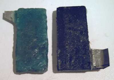
The lanthanum perchlorate positrode and manganese negatrode
after dipping in agar to make "salt bridge" gel coats.
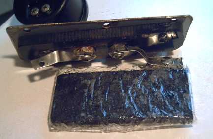
Connecting the electrodes to the terminal bolts in the battery lid.
Solder (including silver solder) would corrode, so it's bolts or else welding.
If it was alkaline, they'd have to be nickel bolts instead of stainless, and nickel metal instead of nickel-brass.
(This is the Mn Negatrode wrapped in microporous cellophane)
"Burning in" the battery in the sealed case.
(still in process - all those ingredients I put in have to electrolyze over about a week's slow charging.)
Pressure has been 3 PSI for several days as the voltage slowly rises.
Next time, I'll do the same thing, but fold it up in front. That way it's the front that has 6 layers and the back with just two. (Or maybe the back only needs one layer, and 3 at the front?)
I haven't yet tried to address the question of whether the cellophane is even necessary in addition to the agar coatings.
The final step was to paint coatings onto a piece of watercolor paper: on one side, ferric oxide; on the other, zirconium silicate ("ion shield" -- ZrO2:SiO2. More commonly ZrO2 is used.), and to spray petroleum seal oil (from a can of "Nutrol" contact cleaner) on the cellophane. The paper goes between the already cellophaned electrodes.
The pH of the KCl electrolyte in the battery checked out as being about 4, which would seem to preclude OH-'es floating around. Here's another idea of the likely chemistry:
[charged] <==> [discharged]
Positrode: La(ClO4)3 + 12 Cl- + 24e- <==> LaCl3 + 12 ClO- [+0.6v ?]
Negatrode: 12 Mn + 12 ClO- <==> 12 MnO + 12 Cl- + 24 e- [-1.1v ?]
[Cell: 1.7v ?]
In this case, the water takes no part in the reactions and the oxygen ions are shuttled around as hypochlorite (bleach). This permits a dry cell (which term actually means "damp cell") with low weight of water.
Although there are here presented three chemistry ideas of how it might actually work, they each provide a chemical pathway to do the same thing: charge the LaCl3 to perchlorate and the MnO to Mn. Whether it discharges to MnO or Mn(OH)2 (or even to Mn(OH)3 or Mn2O3) is of little consequence. It used to be assumed that zinc discharged in alkali to Zn(OH)2, but it turns out it actually ends up as ZnO, yet zinc was being used in batteries long before this detail was known.
After I did the second electrode, I realized that compacting would be easier if two adjacent sides could be removed to let the briquette come out freely, and that this would be made easier if I repositioned one of the side wall bolts (which are underneath) past the end wall so the side could swing out like a gate. (Hah! I knew there was some reason not to chop the compactor to exact length!)
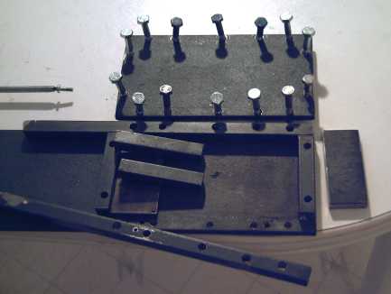
Compactor with more compaction bolts and swivel side
(undoing one bolt underneath lets it swivel to release briquette).
(An end piece may have to come off to freely release full size 3" x 6" briquettes when I start making them.)
January Details