Turquoise Energy News Report #188
Covering
January 2024 (Posted February 13th 2024)
Lawnhill BC Canada - by Craig Carmichael
[CraigXC at Post dot com]
www.TurquoiseEnergy.com
= www.ElectricCaik.com
= www.ElectricHubcap.com
Month In "Brief"
(Project Summaries etc.)
-
"Everlasting" Cu-Zn
Battery Development - [Electro]Magnetic Torque Converter:
Better Designs - Open Loop Air Heat Pumping: - Even Better Air
Compressor & Decompressor Designs - Recap: How OLAHP Works
-
Better Peltier Module Project
In
Passing
(Miscellaneous topics, editorial comments & opinionated rants)
- Scattered
Thots: Tinnitus Measurement in dB - ESD
- Detailed
Project Reports
-
Electric
Transport - Electric Hubcap Motor Systems
* Perfecting the Magnetic Variable Torque Converter: Video - An Even
Better Design!
Other "Green"
& Electric Equipment Projects
* Even Better Air Compressor Design! for Open Loop Heat Pumping
("OLAHP")
Electricity Storage:
Batteries
* Copper-Zinc cell is fantastic! - Many Builds and Tests etc, etc, etc,
etc...
Electricity Generation
* My Solar Power System: - The Usual Latest Daily/Monthly
Solar Production log et cetera - Monthly/Annual Summaries,
Estimates, Notes
Over the cold, wet months of November, December and
January (and on into February) I got back to the "new chemistry"
battery project and started
making breakthroughs. And
I did other energy project project work and gave a lot of thought to
three
other designs, detailed below "battery development":
* Not finding time to do any work on it, I made a video "Perfecting the
Magnetic Torque Converter". As soon as I had done that, after watching
another video on the subject I came up with a major
improvement to make it
"ultra-efficient", rendering part of my design "obsolete". I think I
ought to tackle building the extra component and putting the new design
in the truck.
* I found a better rotary air compressor design for open loop air
heat
pumping (OLAHP) - and improved on it. I also thought of using a
"pelton
wheel" system as the simple rotary decompressor to complete the "most
efficient" compressor-decompressor unit, one of the three main
components
required to gain super high coefficients of performance for indoor
heating. (eg COP 10 at 0°C?)
* And I wrote a recap of how OLAHP works for those who missed
my spring 2020 concept or who want a refresher.
(COP=10 in freezing weather or 1000W of heat
per 100W of electricity, or "How to heat a house almost for free.")
* I ran across a company with thin boron nitride ceramic disks to make better
Peltier
modules with super low thermal resistance and ordered some,
as
well as apparently "the best" thermal heat sink compound on the market.
All for when I have time again. When weather permits I'll
have to focus on my cabin construction (just started putting in the
stairs), and gardening and firewood cutting season approaches. So I
expect I'll have to put the energy projects largely on the shelf, maybe
even until about the same time next winter. (But it would be really
nice
to get the OLAHP going and need much less firewood next winter!)
"Everlasting" Cu-Zn
Battery Development
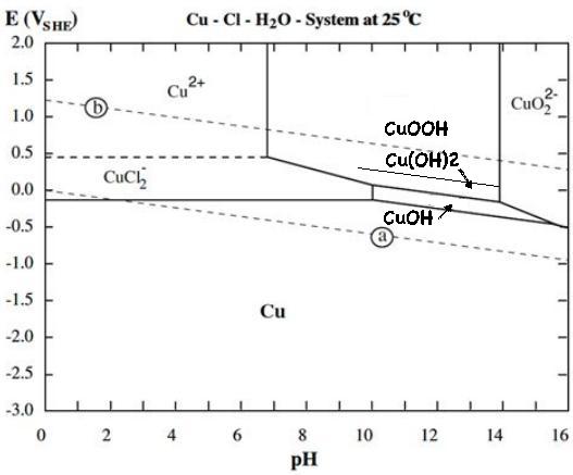
It was exciting to find that copper in a positive
electrode probably charges through four states, not three, to make a
copper-zinc cell of amazingly high energy density despite the low
discharge voltages. No one previously seems to have discovered the
highest energy state, perhaps because previous copper cells (according
to the literature) all used copper oxide (CuO), which seemingly does
not convert to hydroxide Cu(OH)2 under any circumstances.
from:
- metallic copper powder, to
- CuOH (~+1.0V), to
- Cu(OH)2 (~+1.1V), to
- CuOOH (~+1.2V). This form, copper at valence III, isn't found
in any battery literature or Pourbaix diagram. It is a rare but known
substance.
So instead of moving just one electron per atom like
nickel, copper can move up to three. I made (modified) my own Pourbaix
diagram for copper in salt solution. For some reason where I started by
forcing the pH to 12, the cell seems to work just as well at neutral
pH, so perhaps it dissolves at a lower pH than shown:
Whereas a nickel-zinc cell needs 3 to 5 times as much of
the nickel hydroxides substance as the zinc, for copper they're about
equal, greatly shrinking a cell of similar capacity. It may even be
possible to make them with Elon Musk's estimate that one would want
"400 WH/Kg" for electric aircraft, tho 300 is probably more achievable
and 200 should be simple. 200 WH/Kg is good for long range EV's, but
with the low cost main elements, high safety factors, super long life
and high recycleablity I see them as being especially great for
off-grid solar and utility grid scale energy storage.
This was again the main focus of the month. I started with
another cell design concept, a square or rectangular box with multiple
small electrodes. I chose 50x50mm for the active material faces. The
box would have multiple double faced electrodes end to end and the box
ends would be strong enough to prevent bulging with loss of internal
electrical conductivity. In trying to do flat cells I could never
countenance having two faces as thick as the two electrodes inside, as
they need to be to prevent bulging. But if the cell is to have multiple
trodes stacked up the thickness penalty is no greater.
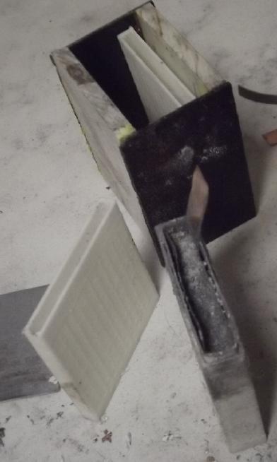 I made a very
small one, 53x60mm x 25mm "long" inside
dimensions, to have just one double electrode in the middle and two
single end electrodes, to be 6:12:6 mm, the end ones being single
faced. A larger one might be for example 6:12:12:12:12:12:6
(|Cu:Zn|Zn:Cu|Cu:Zn|Zn:Cu|Cu:Zn|Zn:Cu|), 72mm long inside. (Now I
really need more 3/16"
or 1/4" ABS sheet. I'm about out of what I moved up to Haida Gwaii
with.)
I made a very
small one, 53x60mm x 25mm "long" inside
dimensions, to have just one double electrode in the middle and two
single end electrodes, to be 6:12:6 mm, the end ones being single
faced. A larger one might be for example 6:12:12:12:12:12:6
(|Cu:Zn|Zn:Cu|Cu:Zn|Zn:Cu|Cu:Zn|Zn:Cu|), 72mm long inside. (Now I
really need more 3/16"
or 1/4" ABS sheet. I'm about out of what I moved up to Haida Gwaii
with.)
But I only put in one single sided zinc electrode and
tested it with various copper powder and copper hydroxide tries,
filling the extra spaces with
pieces of plastic. The zinc has lasted the month with no sign of
letting any dendrites get through or other deterioration. (except I
abraded some of its watercolor paper away putting in and pulling out
various copper electrodes to test them. That doesn't seem to have
killed it yet.)
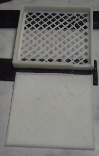 I
designed
electrode "boxes" with porous faces. I ended up
deciding to use them for the copper side but to just wrap the zincs in
treated watercolor paper. In the first boxes the metal current
collector, separator paper and powder all had to be
stuffed in the top edge. The edge was then sealed with heat glue. It
was tedious trying to stuff powder through a thin slit and I changed
them to having an open face. (...two for double faced boxes) Everything
(separator paper, active
powder, current collector) was laid into it flat, then the other face
was glued on with methylene chloride or ABS cement. Only a bit of heat
glue was needed around the terminal tab.
I
designed
electrode "boxes" with porous faces. I ended up
deciding to use them for the copper side but to just wrap the zincs in
treated watercolor paper. In the first boxes the metal current
collector, separator paper and powder all had to be
stuffed in the top edge. The edge was then sealed with heat glue. It
was tedious trying to stuff powder through a thin slit and I changed
them to having an open face. (...two for double faced boxes) Everything
(separator paper, active
powder, current collector) was laid into it flat, then the other face
was glued on with methylene chloride or ABS cement. Only a bit of heat
glue was needed around the terminal tab.
 At first
I was using copper powder. That's the "most discharged" form, and
prohibitively expensive to buy. How could one possibly make economical
batteries?
At first
I was using copper powder. That's the "most discharged" form, and
prohibitively expensive to buy. How could one possibly make economical
batteries?
 Then I thought
to make copper hydroxide powder from solid copper pieces. It didn't
work very well in potassium chloride.
Then I thought
to make copper hydroxide powder from solid copper pieces. It didn't
work very well in potassium chloride.
 It was somewhat better with
magnesium sulfate.
It was somewhat better with
magnesium sulfate.
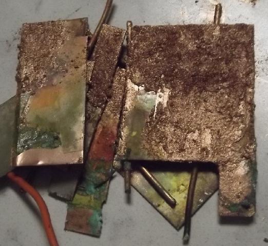
And about there I started using flat sheets of copper (cut
& flattened pipes) hung from a wire in a jar.
 Black ? copper hydroxides using
KCl, brown
mostly CuOH (I presume) from MgSO4.
Black ? copper hydroxides using
KCl, brown
mostly CuOH (I presume) from MgSO4.
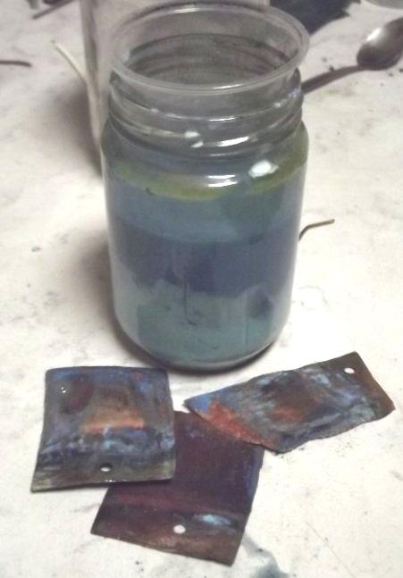 But far and away the best salt, as shown in
a youtube video, is sodium nitrate. It gives beautiful sky blue
relatively pure Cu(OH)2.
But far and away the best salt, as shown in
a youtube video, is sodium nitrate. It gives beautiful sky blue
relatively pure Cu(OH)2.
I ran into a hitch - Westlab wouldn't sell me any.
Apparently it's a "controlled substance" sold only "to corporations for
business purposes". I gave them my Turquoise Energy Ltd. info, but they
haven't replied since. I made some from nitric acid (expensive) and
baking soda to get started. (There's another way with ammonium-aluminum
nitrate "cold packs", but it's complicated.) Then I ordered some from
Sigma-Alderich (or is it "Millipore Sigma"?) on line, where I
previously got an account to get the sodium dodecylbenzenesulfonate. It
arrived in February.
 My cells
(various electrodes in the same container) worked but had very low
currents. I started
trying to increase current drive. First I discovered that the parchment
paper I was using was too closed. It wasn't letting the electrolyte
ions flow freely. Poking a couple of hundred holes in it with a needle
improved current flow substantially.
My cells
(various electrodes in the same container) worked but had very low
currents. I started
trying to increase current drive. First I discovered that the parchment
paper I was using was too closed. It wasn't letting the electrolyte
ions flow freely. Poking a couple of hundred holes in it with a needle
improved current flow substantially.
But what to use? Finally I hit
on paper from basket
coffee filters - great open non-woven cellulose fiber sheets that
somehow manage to keep coffee clear, not letting any fine coffee powder
through.
Then I made the "perforated" plastic box faces more of an open "basket
weave" to assist current flow, counting on the coffee filters to keep
the copper hydroxide
powders in and the cell ends to prevent bulging. [looks like they may
be inadequate. use 2 layers?] These things got short
circuit currents up from around 4 or 5 mA/sq.cm to 17. A reasonable
target, however, is more like 50, so I was only 1/3 of the way there.
Then I remembered to try dissolving the electrode powders (just copper
hydroxide and graphite for this electrode) in acetone to reform into
epitaxial crystals mixed at molecular levels instead of being separate
particles. [February: That seems to be helping too.]
 When I thought
I had everything "perfected" I
still got
variable results. Copper seems to have some idiosyncrasy of charging,
loads and currents and I haven't figured it out yet. It's certainly not
the only electrode that does. Lead batteries for example may be left on
trickle charge for a long time, and then they deliver very poorly and
don't run very long, but if they are then run down and charged again,
perhaps more than once, they are restored to strength. Copper seems to
be - somewhat - similar?
When I thought
I had everything "perfected" I
still got
variable results. Copper seems to have some idiosyncrasy of charging,
loads and currents and I haven't figured it out yet. It's certainly not
the only electrode that does. Lead batteries for example may be left on
trickle charge for a long time, and then they deliver very poorly and
don't run very long, but if they are then run down and charged again,
perhaps more than once, they are restored to strength. Copper seems to
be - somewhat - similar?
Going into February it
seemed copper works great a time or
two, then it starts recharging about like manganese - poorly if at all.
But I bleached the electrode, which should oxidize it without
electricity, and it was, if anything, worse. So it looks more like,
having fully charged, it won't discharge. This may explain why I've
never seen mention of anyone making a rechargeable cell with copper.
(Another reason is that others started with copper oxide. It doesn't
convert to hydroxide.) But the cupro-nickel sheets that got me started
before trying copper and copper hydroxide powders
worked better. They too had problems with deterioration, but
considering the way they did I think I see an answer: to make
acetone-mixed
copper-nickel oxides, similar to what I was doing with nickel-manganese
oxides earlier - except to only charge to copper's reaction voltages,
not
nickel's higher one. When copper is working it performs really well and
I
see great potential.
Also, running the cell down to .5 volts with a 10 Ω load
repeatedly and then recharging seems to strengthen it a little each
time. It looks like I need to make that automatic cycle runner and just
keep cycling them until they work well?
I was hoping to do a special feature on great, working
batteries. Well into February I do seem to be figuring things out, so
maybe next month. BTW The nickel seems superfluous. And it looks like
the art paper around the zinc is gradually "clogging" with copper
substances. That is probably the 'deterioration' problem. ...Better
separator papers!
ElectroMagnetic Torque Converter: Better Designs
I thought my magnetic variable torque converter was a
great design, but I saw another one by Robert Murray Smith on youtube
and realized it would be more efficient. He had just put it together
with 3D printed
plastic gears, but it illustrated the concept nicely. It had a similar
idea: rotate the body of the planetary gear as well as the "input" and
"output" shafts, to create variable conversion ratios. But instead of
two magnet disks, he put an outside-toothed ring gear around the
planetary, to be
driven from a motor with a spur gear. This gave programmable control
over the conversion ratio. My system made waste heat, where his
motor's power actually would add to the propulsion.
Toyota did something like this in the Prius, too. But I
didn't like having a motor that had to be controlled externally, and
with no
intrinsic torque or speed feedback. I once thought of something like it
myself
but it seemed too complicated to build. In addition, this motor would
have to
run faster and faster with vehicle speed. It and its gear would be
whizzing away on the highway.
Another way besides a motor would be a generator.
The harder the generator works, the the more resistance to turning the
planetary gear body would have. The power generated could simply be fed
back to "B+" to run the main motor.
A way to do that with the desired intrinsic feedback would
be with a differential gear on the side of the drivetrain. One side
would be driven by the motor
shaft and the other by the gear body's rotation. The generator would go
to the common center and be turned by the difference in rotation
between the two, generating more current and hence resisting the free
slipping of the planetary body more and more with increasing torque,
thus responding automaticly to torque and speed. This configuration
does again entail spur(?) gears on the differential spinning faster and
faster with vehicle
speed.
But there's a way to make a generator that's reactive to
torque and speed without extra, fast spinning gears: have it as a
component on the main shaft, with big, low RPM components - even the
same 10 inch magnet rotor I'm now using and a matching stator with
coils. Have the "stator" rotate on the planetary gear body and the
"rotor" rotate on the motor shaft. (or vise versa) Then the amount
generated would depend on the slip between them, as with my magnet and
copper rotors. Drawbacks to this would be the need for slip
rings/commutator to
make the electrical connections and that the stator must be strong
enough to spin, at up to perhaps 2200 RPM on the truck, or 1000 on the
car with direct drive to the wheels (for 100 KmPH).
While I early on found that a copper disk's reaction to
magnets doesn't increase
much after a certain point of speed, a generator coil's reactions do. A
big chunk of solid copper (or alume) starts getting current migration
to the surface at quite a low interaction speed, but one must get to
quite a high frequency before the diameter of wires in coils becomes a
significant factor. In the generator the wires go across the magnetic
field and the current is forced to flow through them rather than
eddying around. Wires would thus have more electromagnetic interaction
than the solid rotor, with far less copper. Then by putting in the slip
rings and a diode bridge to recover the energy as electricity to "B+"
for
the motor eliminates even the small amount of wasted energy and heat.
The amount of slip becomes unimportant energy-wise and can be tuned to
the reduction
ratios desired at various torques and speeds. Thus a 10 to 1 or even 5
to 1 planetary gear should be great and the transmission will be super
efficient regardless. There's no need for super high reduction
planetary gearsets.
That should work fabulously and I think it's the design I
ought to do. ...When have
time to make and install it.
Open Loop Air Heat Pumping (OLAHP)
 I didn't do
much actual work on this - but I improved the
design. First I found a better rotary compressor - a real one
(apparently made by "Carrier"). It had a single in/out sliding vane in
the outside housing, and I
realized there's actually no reason to have more than one. The air can
be scooped through the whole circuit and pushed out the output port.
I didn't do
much actual work on this - but I improved the
design. First I found a better rotary compressor - a real one
(apparently made by "Carrier"). It had a single in/out sliding vane in
the outside housing, and I
realized there's actually no reason to have more than one. The air can
be scooped through the whole circuit and pushed out the output port.
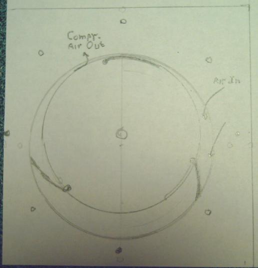 But I
improved on that concept. With the spring loaded - sliding - vane in
the outside housing the whole rotor had to be eccentric. That's not
balanced and it probably vibrates a lot. I'll have the housing
eccentric and the - pivoting - [lower friction] vane on the
rotor. Basicly that makes it the same as last month's design (shown
here) except with just one vane instead of three and the air intake
close to the top.
But I
improved on that concept. With the spring loaded - sliding - vane in
the outside housing the whole rotor had to be eccentric. That's not
balanced and it probably vibrates a lot. I'll have the housing
eccentric and the - pivoting - [lower friction] vane on the
rotor. Basicly that makes it the same as last month's design (shown
here) except with just one vane instead of three and the air intake
close to the top.
 Then I realized there's a
simpler way to do the
decompressor. Instead of feeding air into the center like a rotating
sprinkler (requiring some sort of rotary slip joint in the piping), it
can be fed into the edge of a chamber to drive a Pelton wheel, similar
to hydro power. The pelton wheel would be on the same shaft as the
compressor or geared to it. Having radiated its heat almost down to
outdoor temperature, after decompressing by driving the wheel the (by
now very cold) air is vented outside. It might need a condensation
drain jar underneath, or even a small heater to prevent ice build-up
and clogging.
Then I realized there's a
simpler way to do the
decompressor. Instead of feeding air into the center like a rotating
sprinkler (requiring some sort of rotary slip joint in the piping), it
can be fed into the edge of a chamber to drive a Pelton wheel, similar
to hydro power. The pelton wheel would be on the same shaft as the
compressor or geared to it. Having radiated its heat almost down to
outdoor temperature, after decompressing by driving the wheel the (by
now very cold) air is vented outside. It might need a condensation
drain jar underneath, or even a small heater to prevent ice build-up
and clogging.
I was going to buy a 10 inch pelton wheel, but I wonder if
I can make a decent one easily with the 3D printer or the CNC router or
both? And I wonder if the traditional "split spoon" shape is ideal for
air or if a single "cup" or "spoon" might be better? Or perhaps an
airfoil shape profile might be the most effective?
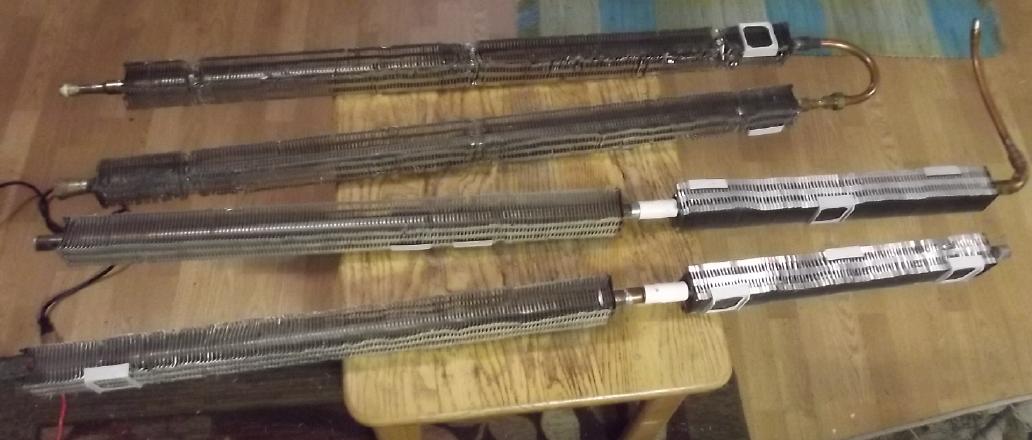 Five lengths of the
indoor-outdoor heat
exchanger pipes, counting the two shorts to be used as one length.
Five lengths of the
indoor-outdoor heat
exchanger pipes, counting the two shorts to be used as one length.
(The sixth, not shown, is two shorter lengths of 1/2 inch copper pipe I
made my own square alume fins for some years ago.)
In actual work, I just cut some pieces of wood for the
outdoor heat exchanger, which will be located indoors against an
outside wall. Since its performance is fundamental to achieving very
high coefficient of performance (COP) for the entire system, I'll make
it the best I can do.
I'll be 2 feet tall by five long and 8 inches thick, with
all my six lengths of finned pipes inside it in a single line that
goes back and forth and in and out, with air channels around the pipe
fins and lots of polystyrene foam insulation. And the better it
is, the more heating capacity the whole system can have and with the
highest COP. 1000 watts of heat from a 100 watt compressor is great,
but 3000 watts from a 300 watt compressor will heat a larger space.
With the first outdoor heat exchanger in 2020 (just one finned pipe) I
noticed the highest COP I got (only 3 or 4) was with the 60 watt
compressor and it went down from there with increasing compressor power.
The piping is to be sloped gradually from top to bottom to
drain condensation. At the bottom a collection/inspection jar will hang
underneath to be emptied as required.
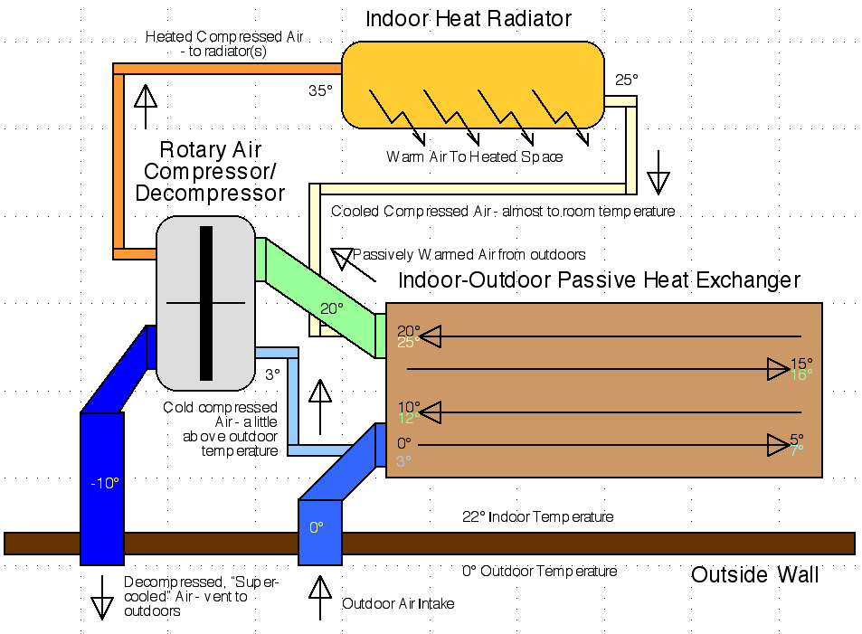
Recap: How OLAHP Works
To recap the open loop air heat pumping (OLAHP)
concept and layout, The efficient
rotary air compressor (see above) draws air from the passively warmed
air
coming out of the indoor-outdoor heat exchanger by direct connection,
or indirectly simply by drawing room air. Drawing room air will
likewise create a suction causing air to flow into the space from
outdoors through the exchanger. (This has the advantage of proving a
flow of fresh air into the space, but a disadvantage of also drawing in
cold air through any leaks in the walls or windows.)
The compressed (and hence heated) air goes into the indoor
radiator to supply heat to the space. In doing so it is cooled to near
room temperature. Note that if the compressor only heats the air by
15°C, say from 20° to 35°, the maximum potential COP is
about 20. [293°K / (308°K-293°K) = 19.533] So if the system
overall is (say) only 50% efficient at 0° outdoor temperature, the
effective COP is around 10. Higher system efficiency or lower
temperature lift by the compressor could give even higher COP values. A
radiator that can radiate enough heat into the space from 30°
instead of 35°
would give a theoretical COP limit of 30 instead of 20.
The still compressed air, now just a little warmer than
room temperature, then goes through the pipes in
the indoor-outdoor heat exchanger, being cooled toward outdoor
temperature as it warms the outdoor air
coming in through the channels surrounding the finned pipes. The more
effective this heat exchange is, the less work the compressor needs to
do and the higher the COP will be. This unit is located indoors,
drawing fresh outdoor air through a duct in the wall.
Finally the compressed air, now perhaps just above outdoor
temperature, is vented into the rotary decompressor (Pelton wheel) to
assist the compressor and the decompressed air is vented outside,
colder than the outside air. (& away from the air intake.) This is
the "open loop" aspect, where the passive heat exchanger draws fresh
air at outdoor temperature and doesn't have to reheat the same air it
has "super cooled", as a closed loop refrigerant based system has to.
So there is no "outdoor radiator" unit.
 Open Loop Air
Heat Pump
Open Loop Air
Heat Pump
Better Peltier Module Project
Having received no answer about beryllium oxide ceramic
'plates' or powder some months ago, but instead a warning about the
high toxicity of beryllium oxide from a reader, I had set this aside.
(I was aware of the toxicity, but I hadn't considered that it might be
a bad material to sell to unaware consumers who might, like me, do
"DIY" peltier module projects with it.) But on
the 17th I
have found a place on AliExpress that has boron nitride round disks,
40mm x 1mm thick. That's close enough to give it a try.
Just to make sure of my memory, I went back to TE News #182 and found
this:
Boron nitride
("graphite" structured)> 30
or 600, depending on orientation
("diamond" structured) 740
Two figures looked fabulous, but the "30" was no better than aluminum
oxide. The store's offering was called "white graphite". (boron nitride
that's like graphite except white.)
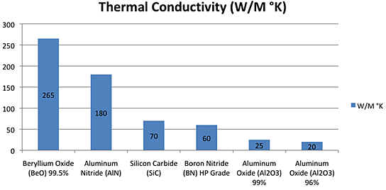 Then I went to
TE News #183 where there was this thermal conductivity chart. Aluminum
nitride, which I found they also have, is said to be six
(or more) times as thermally conductive as aluminum oxide, presumably
in
any direction of heat travel, and so much more certain to give good
results.
Then I went to
TE News #183 where there was this thermal conductivity chart. Aluminum
nitride, which I found they also have, is said to be six
(or more) times as thermally conductive as aluminum oxide, presumably
in
any direction of heat travel, and so much more certain to give good
results.
In fact, it is slightly more conductive than actual alume
metal
alloy,
so spreading the heat out by using (eg) a 50x50mm plate to cover a
40x40mm peltier module should considerably assist getting the heat from
the module into the heatsink.
I ordered 10 pieces, 40mm diameter by 1mm thick. (That was
the size. Not square, nothing bigger. I'm sure I can work with
that as well as with any.) For "when I have time" to look at this
project again. But I haven't even begun to look at how one deposits
copper to form a "printed circuit board" by an additive process onto a
piece of ceramic. Nor am I confident of successfully placing and
soldering all those tiny thermocouples by hand. But I have the ceramic!
:)
Also: I found
and bought what is reputedly the best heatsink grease available,
"Kryonaut", raved over by CPU overclocking fans. I have been planning
to see if just using that gives still better results with the copper
heatsinks. (when I have time, of course!) A peltier module that can
drop a camping cooler's temperature by 20°C or more instead of just
10 to 13° would make them a whole lot more useful! The copper
heatsink got mine improved from a 12.5° temperature drop to 16°
[TE News #181], so copper
heatsinks instead of alume alloy ones get it half the way there. That
leaves the heatsink paste and the electricly insulating skin of the
module
itself as thermal blockages. Then there's the thermocouple elements
themselves. I'll have to leave possible better designs of thermocouples
to
others. (And I still wonder why no one else has tried these other
things to improve the thermal conductivity aspects of Peltier modules.)
Cabin Construction
Over the cold, dark winter months construction has been
lagging, not to say stalled. That of course is why I've had time to
look into creating batteries again. However, cabin construction and
outdoor work are going to be very high on my priorities as the weather
improves and daylight lengthens. Maybe this summer I can complete the
walls, windows and doors, and work on the finishings at a leisurely
pace from inside?
Gardening
Not much to say. The chickens have been scratching up the
garden beds, but they're not very good at digging out grass and weed
roots.
In
Passing
(Miscellaneous topics, editorial comments & opinionated
rants)
Scattered
Thots
* Tinnitus Measurement I had been thinking there was no way to
measure the intensity of the ringing in one's ears, when there is no
external audio sound. But I've thought of one. Turn on a signal
generator with a tone similar to the ringing. (don't buy one, there are
web sites) and set the intensity so that it is similar in volume to the
tinnitus. Use a decibel meter near your head to measure the intensity.
The result may be somewhat crude, but it should be able to
tell 10 dB from 30 dB from 50 dB from 70 dB. Since I moved to this
house on Haida Gwaii much too close to the 14400V power line, mine has
been awful. I'll find out: I ordered a nice looking dB
meter claiming good specs from AliExpress for just 20$ or so.
It came in early February and while there's much
uncertainty, I twice measured it and got around 42 dB, plus or minus
maybe 3. There were some suspicious things. It read that ambient noise
was around 35-37 dB wherever I went (a little more if there was any
slight noise I could hear), which seemed odd. Even if I stuck it
between two pillows it didn't drop, or not much. (I think I got it down
to 34 once.) Another problem was that it didn't seem to respond well to
frequencies over around 3500-4000 Hz despite its claim of responding to
20-20000 Hz ±1 dB, so I couldn't set the on-line signal
generator to a pitch near the high frequency tinnitus. I could hear the
sounds clearly from the speakers, yet the meter read under 40 dB. A
third trouble was that even the pitches it did sense were very
direction sensitive. I could hear them clearly or even not hear them
depending on the position and orientation of my head, including in one
ear or the other, and the meter's microphone also could locate the
"nodes" of higher and lower volume.
ESD
(Eccentric Silliness Department)
* Insidious spyware: There are a million microphones in a phone.
* Someone saw the tax agent coming. He got out his wallet and started
tossing money at him. This is known as "spontaneous remission".
"in depth
reports" for
each project are below. I hope they may be useful to anyone who wants
to get into a similar project, to glean ideas for how something
might be done, as well as things that might have been tried, or just
thought
of and not tried... and even of how not to do something - why
it didn't
work or proved impractical. Sometimes they set out inventive thoughts
almost as they occur - and are the actual organization and elaboration
in writing of those thoughts. They are thus partly a diary and are not
extensively proof-read for literary perfection, consistency,
completeness and elimination of duplications before
publication. I hope they may add to the body of wisdom for other
researchers and developers to help them find more productive paths and
avoid potential pitfalls and dead ends.
Electric
Transport
"Perfecting the Magnetic Variable Torque Converter": Video
[12th] I had a new idea about the variable torque converter. It was
hard to get enough magnetic interaction between the magnet disk and the
metal disk (copper, alume). If it needed less flux requirements could
be relaxed. I had also noted in my calculations the reduction ratios
decreasing quite rapidly at rather low vehicle speeds, which is
probably not best for good acceleration at low speeds. I had bought the
highest ratio single stage planetary gear available, 10 to 1. I'm sure
the solution to both problems is a higher intrinsic reduction ratio - a
two-stage planetary gear. A 30 to 1 gear would multiply the magnetic
forces by 30 instead of 10, considerably easing the requirements for
the flux interaction. A 40 to 1 or so could make a Chevy Sprint
motor-to-wheel variable torque converter much easier to put together.
Seeing that I have had no time to work on it I decided to
just put up a video about it to follow the previous ones on the
subject. I've demonstrated the principle in the Miles truck. At this
point it'll be up to commercial developers and manufacturers to build
the design to their requirements and likings. I explicitly state in the
description of the video that the technology is all free and in the
public domain. I have taken out no patents or restrictions to use.
Somehow I feel this spreading of the idea is a major
achievement. with no more work than a day's video production and
editing.
Perfecting the Magnetic Variable Torque Converter
https://youtu.be/472zxAjCI6Y
(And here are my previous videos on the subject:
Automatic Variable Mechanical/Magnetic Torque
Converter [Theory & 1st tests]
https://youtu.be/9KWASx5C6ZE
- Initial concept & tests
https://youtu.be/aqG2Ol4y9Jw - Just the tests part without the
theory/concept
Magnetic Torque Converter - February 2023 Tests
[Improved but not fabulous]
https://youtu.be/MFbFC5YkvTM
)
Naturally, soon after I thought mine was, in concept, as good as it
gets, I found a video by Robert Murray Smith:
2197 The Infinite CVT And Wind Turbine Control
https://www.youtube.com/watch?v=uyi1Nv7kks8&ab_channel=RobertMurray-Smith
For efficiency this beats mine. But it has no intrinsic
feedback to the "control" motor. It would need electronic sensors and
microcontroller control and has fast-spinning gears and motor that will
have to run at high speeds on the highway. Still, it was the
inspiration for my still better design covered in "Month
in Brief"!
(It is probably a great idea for a wind turbine to achieve a more
constant voltage in low winds, but Smith errs in thinking it could save
trouble in high winds. If the generator isn't loading down the blades
to the point of overheating itself, the blades will spin too fast and
fly apart.
With wind energy being the cube of the wind speed, high
winds are a really serious hazard. I should think the best way is (a)
to have a secure mechanical brake that can stop the blades and (b) I
presume big windplants have a powered aiming ability since I don't see
any aiming vanes... it should turn as much as 90° from the wind if
it's too strong - before it's going too fast or the generator inside
gets too hot. ...or there's too much lateral pressure on the tower. And
then if needed put the brake on. These seem to me like elementary
precautions. But one sees windplants burning up and falling down on
youtube without knowing what precautions and safety systems were in
fact implemented. Were there any? Should they have been adequate? Why
did they fail? How rare or common is it for them to fail over their
service life? BTW how long is their service life? - one also sees them
or their blades being discarded because the blades have deteriorated -
pitted - from running through the air at higher speeds. Are they using
something like PP epoxy, or just cheap fiberglass? What (if anything)
is inside the blade for tensile strength?)
Other
"Green"
&
Electric
Equipment
Projects
Even Better Air
Compressor Design!
for Open Loop Heat Pumping ("OLAHP")
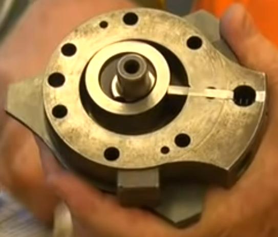
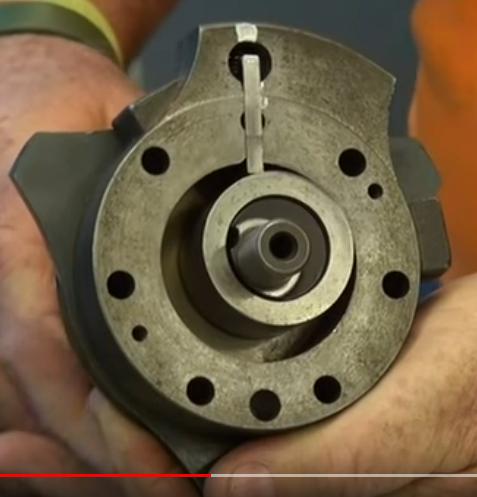
An Even Better Compressor
Start of a
cycle: cam has
passed the vane and air intake, and will
sweep the air around and out the output at the left of the vane.
 [11th]
I looked on youtube for interesting videos and it
suggested one with another rotary compressor. It wasn't very
interesting but after the end another was suggested. That one looked
interesting because it showed an actual disassembled unit from a
production heat pump or air conditioner, not just a theoretical
computer animation. It appeared to be a maintenance video explaining
the compressor and all the actual workings and disassembly/assembly. It
was different again from anything I've seen before - and it was Real, a
production unit!
[11th]
I looked on youtube for interesting videos and it
suggested one with another rotary compressor. It wasn't very
interesting but after the end another was suggested. That one looked
interesting because it showed an actual disassembled unit from a
production heat pump or air conditioner, not just a theoretical
computer animation. It appeared to be a maintenance video explaining
the compressor and all the actual workings and disassembly/assembly. It
was different again from anything I've seen before - and it was Real, a
production unit!
The motor shaft had an offset cam instead of the housing
being offset or an elliptical housing. Outside of the offset cam was a
ring "sleeve". There was just One sliding vane. As the motor turned,
the sleeve drew in refrigerant (or air) from one side and sent it
around in almost a full circle to where the cam pushed the sleeve
against the outside, until it reached the vane with a vanishing volume
and sent the compressed refrigerant (or air) out the exit. So for
virtually the whole rotation air is being drawn in on the right side of
the vane and simultaneously compressed on the left.
The "sleeve" could as easily have been a larger cam on the
motor shaft, but instead it slips on the motor cam and doesn't have to
rotate with it, minimizing friction.
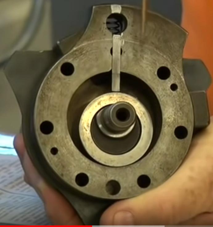 Midway. Air to left of vane is
being pushed
into the outlet.
Midway. Air to left of vane is
being pushed
into the outlet.
Air to right is coming in the inlet to the right of the vane.
Air on left of the vane is well
compressed and
being pushed out.
Still more air is coming in the inlet to the right of the vane.
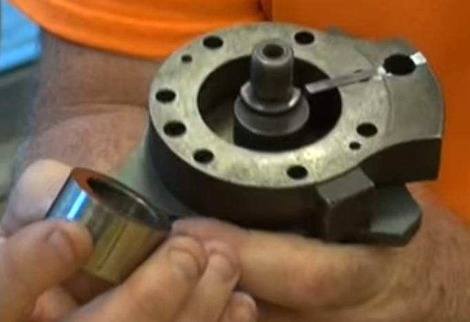 The sleeve on the offset shaft
doesn't actually
have to spin, so it
The sleeve on the offset shaft
doesn't actually
have to spin, so it
slides on the spinning offset shaft, a smaller diameter with less
friction.
This is better than anything I've seen yet, and the fact
that it's in production probably says it's the best of the ideas. Now
we take that and replace the sprung sliding vane with a pivoting vane
(in the same place, maybe with a small spring) to further reduce
friction, use slippery UHMW in the housing, add the decompression
assist section ["Pelton Wheel"]
to
help
turn
the
same shaft, and I think it should be "the best"
...unless something even better that I've missed until now turns up.
But at this point it's hard to imagine anything simpler or more
effective.
I don't suppose I could find one to use it instead of
making one (it might be "Carrier" brand) , but there's nowhere
to attach a decompressor anyway. But it's well I haven't gone any
farther on last month's design!
Hmm... The cam on the motor shaft might be replaced with a
vane or just a leaf spring that pushes the UHMW ring "sleeve" against
the outside edge? Oh, wait... the air pressure would push it open. It
would have to be a solid vane. Or there might be an offset bearing race
on the motor shaft to hold the ring - definitely lowest friction?
It occurs to me that only a "lobe" sweeping around is
actually needed to move the air. But it has to press the vane out to
the edge and let it back. The ring is probably the smoothest way. I
could also see the ring sleeve and outside edge having gear teeth that
mesh, virtually eliminating air leaks from that edge. (That still
leaves top and bottom leaks.)
[14th] It occurs to me that driving an off-center lobe is probably
going to cause a lot of needless vibration. I think I'll return to the
centered rotor with offset outer housing. So the pivoting vane will
have to be on the rotor. But the video was by no means a waste: now I
realize that only one vane is needed, sweeping around the full circle.
That will have the least friction. (and be the easiest to write the
G-code for routing out one slot!) And to leak out top and bottom
(except across
the vane), air has to leak across the big plastic rotor instead of just
a narrow ring.
A Better Decompressor
The same morning I had another inspiration about making a
decompressor. Instead of feeding air in at the center of a "rotating
hose sprinkler" that shot air out the ends backward, one could have a
fixed nozzle driving a "pelton wheel" on the compressor shaft. The
decompressed air could also be removed at a fixed point (almost
anywhere?) on the side of the housing. No rotating air connections! (It
would still be in an enclosed housing because the decompressed air
coming out will be cold, maybe colder than outdoors, and has to be
piped outside.)
Hmm, I wonder if I can just buy an appropriate pelton
wheel in a housing? Even if I had to change the nozzle and perhaps the
output opening, it would probably be much easier than making my own.
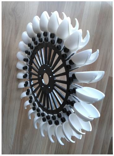
[15th] I tried to order a
260mm diameter pelton wheel with 25 somewhat
cheap looking plastic fins. It said it couldn't be shipped to my
address. I sent a message asking if the seller could mail it, but he
didn't understand that the web page literally wouldn't let me order it
because of his one limited shipping option.
Then I started thinking that
"airfoil" blades would probably be better for air. Pelton wheels are
for water.
Indoor-Outdoor Air Heat Exchanger
I gathered together the radiator pipes Mike gave me when I
was
first working on this project in 2020. The six pieces (counting one I
made myself, not shown) made 246
inches length of fins.
Since this is a crucial component for getting a very high
COP I decided to put them all together in a single length, folded into
four rows with a shallow vertical descent angle from top to bottom so
condensation would accumulate in one place, where I intend to place a
jar (or something with a valve?) so one can see when it's getting full
and empty it. The housing with 2" styrene foam insulation (R 10) on all
sides and between the rows will be 60" x 24" x 8". That's 5/8 of a
sheet of thin plywood and some 2" by 8"s, and a lot of foam.
The outgoing compressed air (being cooled by the incoming
outdoor air) flows through the pipes. The incoming outdoor air flows
outside them, all around the fins, picking up heat. The warm air output
may
or may not be directly connected to the input of the air compressor. If
not directly connected, the compressor nevertheless draws in air,
which will flow into the heated space through the heat exchanger. The
advantage of this is almost free fresh air. The disadvantage is that
air will also be drawn in through air leaks in the structure.
Electricity
Storage
Everlasting Copper-Zinc Cells with Plastic Pocket Electrodes
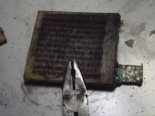
[1st - large clamped flat cell.] Trying a long discharge with 50 Ω
after charging overnight at 1.4
V. (just 17 mA by AM) It started out low at only 1.006 V, but it
dropped in voltage very slowly. I had tried this a year ago with cobalt
oxide (at a slightly lower voltage) but found it wouldn't recharge
[TENews176]. If the copper oxide was pure it probably wouldn't either,
but alloyed/in solid solution with nickel it seems to work. I'll know
for sure when I try to recharge it and run a second test. [February
note: Copper alone, with some graphite, works fine. Some of the
presumptions weren't quite right.]
The first long test ran for just over 13 hours and produced this graph:
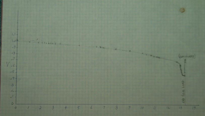
One can see the "cliff" at about .65 volts at about the 13 hour mark
where the copper oxide [Cu(OH)2, CuOH] has all been reduced to copper
and voltage falls
quickly. Then at about .45 volts it levels out again. This would be
where the nickel hydroxide component starts getting reduced back to
nickel metal. Not only is this a pretty low voltage, it was dropping by
3 mV/minute, probably indicating that there wasn't a whole lot of it
available at the surface to react. I declined to push it further. It
just might be undoing the conditioning from all the previous charging.
In considering that 50 ohms is a very small load (20 mA at
1 volt) and yet there was considerable voltage drop below the open
circuit voltage (perhaps 100 mV initially), and that 13 hours of that
is only about 1/4 of an amp-hour, it must be remembered that in this
test cell the active cupro-nickel (a) is solid .51mm (#24 gauge) sheets
rather than powder with a high surface area to volume, (b) is at 70:30
somewhat short of nickel in ratio to the copper and (c) that as of the
last opening, mostly only one side of one sheet had the coppery color
indicating it was being employed. (Why that is I'm not sure but will
run experiments charging sheets in a vat with the platinum negative.) A
well compacted 60:40 cupro-nickel or a 50:50 monel would doubtless
supply much higher currents with much lower voltage drops for much
longer times.
In fact, now that I understand the voltage is only around
1.0 volts rather than 1.2 or 1.3, I think I should try the monel powder
filled perforated tube electrode again.
Recharging after that (at 1.4 volts) of course also took hours, mostly
at not much higher current than the discharge:
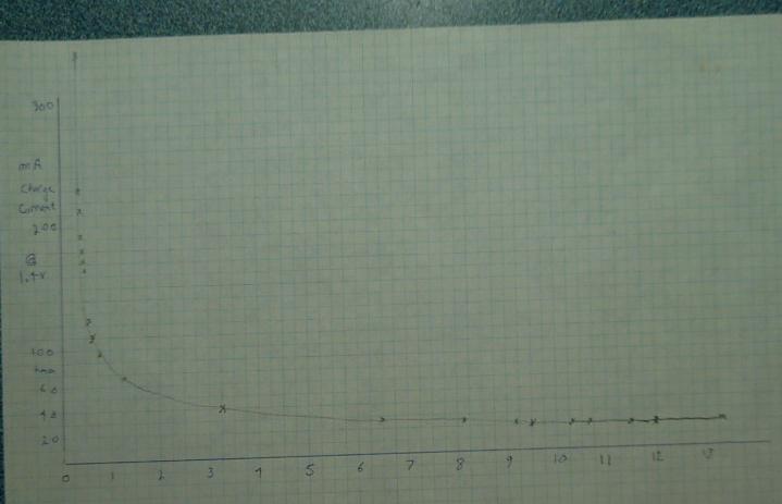
With the charge still at 22 mA, I turned the charge voltage down to 1.3
V. After a short period of adjustment, the current dropped to about 16
mA.
At 1.2 V, it dropped to 10 mA and at 1.1 V, to 4 mA. At 1.0 V setting,
current reversed and -1 mA was flowing from the battery to the power
supply, whose meter continued to read 1.1 V. Again the currents would
be much higher at lower voltage (eg, 1.2 instead of 1.4 V) if there was
more active substance in the cell.
[2nd] When I briefly changed from 'charge' to 50 ohm 'load' the voltage
dropped a lot. I changed it to 1.6V charge for 3(?) hours. At 10:00 PM
after it sat a few minutes I started the second long load test. It
still started low, .938 volts. But it rose in a couple of minutes to
over .95, and over the first 1/2 hour to .964V. There it stayed for
about 15 minutes before losing a couple of millivolts. To me anything
under 1 volt sounds so low... yet .96 is only 40mV below where it
started on the first test. What counts more is how long it runs. I
started it in the evening presuming it will run all night and finish
sometime in the morning when I'm back to see the last phase.
Somewhere in the first days of January I ran some tests on
the flat cell and found that lower voltages that were disappointing me
were owed to poor connections between the CuNi sheets inside the cell.
(The inner sheet did most of the chemistry, but the terminal tab was on
the outer sheet, and the surfaces naturally oxidized.) The chemistry
was working fine. Tightening the clamp screws brought the voltages back
up.
Nickel Manganates: Manganese, not Nickel?
[5th] I thought once again about how one might get manganese to
recharge. It suddenly occurred to me that the nickel manganates
electrode (or nickel-manganese oxides) mix I had created in several
variants and tried to make work just might be exactly that. I had been
trying to charge it to nickel oxide reaction levels, but why might it
not just as easily charge only to the lower manganese oxide levels,
just as the cupro-nickel charged to the copper oxide level rather than
the nickel oxyhydroxide level? Why had I never, ever tried doing that?
Why
was I so sure that the previously untried mix should do one over the
other? That might explain the rapid voltage drops under load to around
1.3V(?) or so when I was expecting 1.8+. I might have been
deteriorating the whole thing trying to charge it at too high a voltage
(2.1V) as if it was nickel-zinc instead of manganese-zinc (~1.6V).
That level had oxidized the cupro-nickel sheets. Perhaps what I had
done should instead
have been a way to make a rechargeable manganese electrode? To be fair
to myself,
for many years I was unaware that a manganese oxides electrode in fact
wouldn't recharge, so I wasn't looking for a way to make it do so.
I want to try it out some time to make "rechargeable
Mn-Zn" cells
at some point. Copper has more energy, but Mn-Zn would be useful
especially for dry cells since they
would be the expected 1.5 volts and (with all the techniques I've
developed) indefinitely rechargeable. (at
least until the dry cell actually dries out with charging as they
eventually do.)
New Cell Idea
 [6th] I had also been
toying with "How are multiple electrodes stacked
end to end in 'prismatic' cells?", when they seem to need to be held in
compression so they don't swell and lose connectivity. The answer
(without it being mentioned or readily apparent in diagrams) is
probably that such cells are constructed so that there was no space at
either end for them to expand into. I had been trying to make "flat
cells" with a single electrode pair and thin plastic on their faces.
The thin plastic bulged, but I couldn't conceive of using thick plastic
to hold such a thin cell - the cell walls would be thicker than the two
electrodes they enclosed. The next morning these things came together:
why not multiple smaller electrodes stacked in a cell with thick
plastic at each end? Even thin cell sides would hold the ends together.
Although the length would be fixed and the thickness of one-off "DIY"
electrodes would vary, shims could be inserted into one end to occupy
excess space. Having a bit of excess space would ensure that the
electrodes wouldn't break up by trying to scrunch them in sliding them
sideways into place.
[6th] I had also been
toying with "How are multiple electrodes stacked
end to end in 'prismatic' cells?", when they seem to need to be held in
compression so they don't swell and lose connectivity. The answer
(without it being mentioned or readily apparent in diagrams) is
probably that such cells are constructed so that there was no space at
either end for them to expand into. I had been trying to make "flat
cells" with a single electrode pair and thin plastic on their faces.
The thin plastic bulged, but I couldn't conceive of using thick plastic
to hold such a thin cell - the cell walls would be thicker than the two
electrodes they enclosed. The next morning these things came together:
why not multiple smaller electrodes stacked in a cell with thick
plastic at each end? Even thin cell sides would hold the ends together.
Although the length would be fixed and the thickness of one-off "DIY"
electrodes would vary, shims could be inserted into one end to occupy
excess space. Having a bit of excess space would ensure that the
electrodes wouldn't break up by trying to scrunch them in sliding them
sideways into place.
Matt gave me some copper
powder to try out a copper
electrode with. What were the chances that someone local who I knew
would have a substance that almost no one uses? Only one store on all
AliExpress sells it.
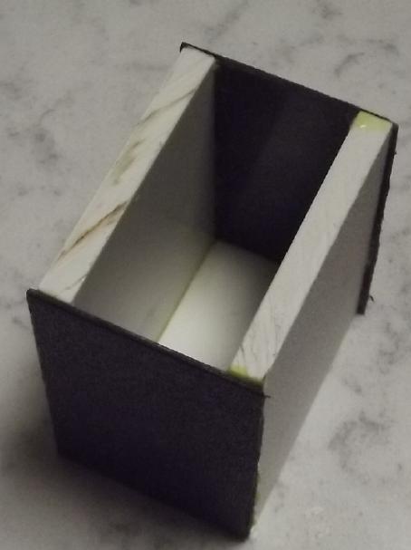
I decided to try both things at once: a copper zinc cell
with copper powder & graphite, and the new cell case idea with just
three electrodes - two 6mm thick on the ends and one 12mm thick in the
middle. I went right out to the freezing shop, fired up the scary table
saw I got at the refuse station a couple of years ago and left out in
the rain since, and cut a few bits of my dwindling stock of thick ABS
plastic pieces. It cut it without melting the edges like my radial arm
saw does. In the evening I glued it together, an open top box for four
24mm thick of electrodes that should be strong enough to not allow them
to bulge. (The top comes later.) I sized it 53mm wide to hold
electrodes made with my 50x50mm compactor, and 25mm long, leaving room
for the papers.
[7th] Luckily I tried filling it with water before making the
cell. In spite of using apparently lots of ABS cement, and in spite of
no light showing through the seams anywhere, it had a pinhole leak.
Good grief! I smeared on more glue. Perhaps what I need is a really
fine saw blade to make really smooth cuts. (And a special push stick to
hold down the little, thin, light pieces as I cut. Yikes!) That might
just
solve my forever making cells that leak? (The poor carpenter blames his
tools, but the good carpenter gets better tools?)
The next change was to make the current collectors a
little smaller to leave a couple of mm so they wouldn't press on and
maybe cut the papers. The final thing I wanted was paper envelopes to
slide the electrode briquettes and current collectors into, open only
on the tops. Was there a way to glue papers into envelopes? Heat glue
might work. Just wetting watercolor paper, forming it and letting it
dry might work for it. Or maybe just cutting it 55mm wide and putting
it in as "U" shaped pieces blocking the entire cell width between
'trodes
would work? I'm not so sure about parchment paper. Same thing? How sure
would that be to not allow shorts? Since it would be much simpler I
decided to try it.
 Ideas got modified as I went. Like the monel powder, the
copper + graphite powder (100g + 15g) wouldn't form a 'briquette' but
merely crumbled back into powder at any touch. Finally I compacted it
directly onto a CuNi flat sheet current collector and put it into the
tipped-up cell like something on a spatula going into an oven. I put a
sheet of parchment paper over that for a separator.
Ideas got modified as I went. Like the monel powder, the
copper + graphite powder (100g + 15g) wouldn't form a 'briquette' but
merely crumbled back into powder at any touch. Finally I compacted it
directly onto a CuNi flat sheet current collector and put it into the
tipped-up cell like something on a spatula going into an oven. I put a
sheet of parchment paper over that for a separator.
I could see that this would make an ideal battery... if
done with great precision by a machine. A man with tremors was
something else. Three electrodes. Could I put it together without
everything crumbling into a mess, and with the separators actually
preventing shorts between them?
I decided to scrap the
clamped flat cell and use the zincs from
inside it. Uncovering the zinc side I found it had swelled up from 4 or
5 mm to 7 or more. Much of the zinc was now oxide (ZnO, discharged)
especially around the edges. Deeper in and especially against the
copper current collector was metallic zinc, and it was actually hard to
crunch through it with a thin knife. The copper foil underneath was
still bright and shiny.
But I cut another current collector and then a piece
simply to protect the papers and put them in. I pried them apart with
two screwdrivers and made a space. I measured out 21 grams of
copper/graphite powder and started filling with a spoon. Then I stuffed
it down with a couple of thin, flat pieces of ABS. I wondered how
little of the 21 grams would go in. When it was all in and the space
not anywhere near filled, I wondered if I would ever finish filling it.
The first 'trode had 21 grams of copper powder and the second one about
27. 40 amp-hours or so?
 There was
copper powder everywhere and I wondered if there
was any chance it wasn't all shorted out. But I filled it with
electrolyte and the voltage between negative and the two positive
terminals read .83 V and .84 V. They would only drive a few milliamps
if shorted since the copper was totally discharged. When I started the
charge to my surprise it was only 26mA. But where the zinc briquettes
measured in the lower 10's of ohms, the copper powder was megohms, or
even tens of megohms, so maybe I shouldn't have been surprised. It
seemed very strange since copper is the second best conducting element
on the whole periodic table and I had added graphite to ensure good
conductivity. Surely the copper powder particles weren't in good
contact with each other? Pressing down on the open top of powder in the
electrode with the plastic piece didn't help. (That was
conductive graphite I added, wasn't it? Yup, 1's of ohms. In fact, the
copper powder sufficiently pressed between two sheets of metal was even
lower 1's of ohms.)
There was
copper powder everywhere and I wondered if there
was any chance it wasn't all shorted out. But I filled it with
electrolyte and the voltage between negative and the two positive
terminals read .83 V and .84 V. They would only drive a few milliamps
if shorted since the copper was totally discharged. When I started the
charge to my surprise it was only 26mA. But where the zinc briquettes
measured in the lower 10's of ohms, the copper powder was megohms, or
even tens of megohms, so maybe I shouldn't have been surprised. It
seemed very strange since copper is the second best conducting element
on the whole periodic table and I had added graphite to ensure good
conductivity. Surely the copper powder particles weren't in good
contact with each other? Pressing down on the open top of powder in the
electrode with the plastic piece didn't help. (That was
conductive graphite I added, wasn't it? Yup, 1's of ohms. In fact, the
copper powder sufficiently pressed between two sheets of metal was even
lower 1's of ohms.)
Then again, when the copper charged and formed hydroxide,
it was going to need more room than the metal. Part of the theory is
that as it charged and discharges, the particles will link up and form
low resistance paths. That this happens is shown in that once the cell
has charged at a patheticly low rate and is then discharged, it
recharges at much higher currents up to the point it was charged to
previously. Presumably it will eventually be fully charged and far more
conductive. I may be having a problem with that because of too much
copper in the cupro-nickel current collector sheets? It gets involved
in the reactions (which is of course how I first noticed copper).
(Should I try a graphite foil current collector?)
Then the first copper 'trode shorted to the zinc. I had to
disconnect it. I couldn't see the top of its separator parchment paper.
I thought I had been careful to make sure it didn't get sucked down in
when I put in the zinc 'trode, but it was completely vanished. As I
feared, I hadn't managed to do everything perfectly enough to make it
work. Hmm... If I had made and used the metal insert sooner, the
separator couldn't have got pushed down when I put in the zinc section.
Maybe what I need is perfect my techniques rather than give up on this
form of cell assembly so soon? But it took my whole day and was pretty
disappointing.
The second side was charging at just 10mA. It was going to
take a while to get up over 20 amp-hours that way! I raised the charge
from 1.4V to 1.6. Maybe some changes to the CuNi sheet would cause
better connections to form? Current rose to 29mA.
After a while there seemed to be a lower resistance path
between '-' and the remaining '+'. Had some powder got around the
separator sheets? Zinc dendrites getting by the dopant and the SDBS
papers? With everything stuffed together there was no way to fix
anything: the cell had to come apart and start over. I'm sure I've
played this broken record over and over.
I need to be able to handle
individual electrodes. The
round tube "perforated plastic pocket electrodes" had some poor
characteristics, but they were makeable, individually serviceable, and
they worked. What about doing similar but rectangular envelopes, which
could be stacked completely filling the rectangular cell so they had
nowhere to bulge? If each electrode was to be 6mm thick and doubles
were stacked with the current collector between making 12mm, an awful
lot of 'trodes could still be stuffed into a small space, almost
completely filling it.
Before bed I designed the "fat" and "thin" 50-50 (mm)
pockets, sliced them to G-code and took them to the printer. Prints?
Mañana.
[8th] I pulled the electrodes out of the open box. I had compacted the
last copper 'trode as I added more and more powder, and they were well
jammed in. It was hard prying the outer current collectors out and
there was certainly no room for anything to swell without breaking the
box. On the bright side, the copper with graphite was fragile solids
rather than loose powder and the resistance through a clump of it to
the sheet metal was mid 1000's of ohms instead of upper 1,000,000's.
I printed two of each 50 x 50 mm pockets, but the thin one
looked too skinny to work with. By the time the current collector and
papers were in, I didn't see how I could manage to put in the actual
powder. The thick one I could fit in one side instead of two. The
reason was that 2mm of each was lost in plastic thickness. I needed to
make them 6mm and 12mm I.D. instead of O.D.
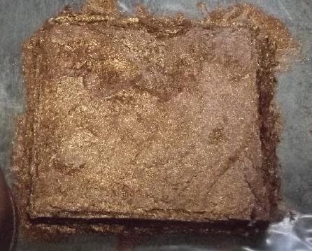
I only managed to fill one 'fat' 'pocket' with one zinc
briquette on one side of the copper sheet, with an old piece of doped
parchment paper and a new toluened watercolor paper.
[9th] I soaked the zincode
in SDBS for an hour while I filled the
other 'fat' pocket with a copper powder trode. I thought of how
performance kept deteriorating as the CuNi sheets oxidized (and how I
really wanted monel with more nickel than copper), and at the last
minute I removed it and put in a graphite foil current collector
instead. The empty cell had weighed 19 grams and after filling it was
43 (46 with the heat glue applied), but the CuNi had been 11g and the
graphite foil would have been about 3g, so 11 for the cell leaves 32
grams of copper powder - a theoretical 23.6 amp-hours for 23mAH/g / 46g
= 500 amp-hours/Kg. The zinc side is probably similar. With a
lightweight case and not a lot of water needed, even at 1 volt that
would be maybe 400 WH/Kg. Theoretical. That would be pretty impressive
if even half attained. Now, might it for once actually get any
substantial fraction of those amp-hours without zinc dendriting, the
"+" current collector or other component deteriorating or the cell
springing a leak first?
But when I pulled it out, there was a suspicious amount of
zinc in the dripping liquid. I became sure there was a gap somewhere. I
decided to try a little origami and wrapped a piece of watercolor paper
around the entire electrode box, folded around the bottom and open only
at the top (hopefully) above the water line.
The cell charged at a
whopping 1mA. At that rate it would
take 40 days and 40 nights just to get to one amp-hour! I blame using a
graphite instead of monel current collector... but I really don't know
why it was so slow. But it did slowly take on some charge over the day.
Over the day, with no apparent leaks, I added electrolyte
several times. Presumably the copper was charging to Cu(OH)2 and using
up the water.
 [10th]
Overnight it occurred to me that if the electrolyte water was
being consumed and I kept adding more, the salt concentration must be
getting really high. In the morning it would drive a 50Ω load near .5V
instead of .6V - ug! There should be virtually NO voltage drop with a
50Ω load! I filled it (the small voids not occupied by electrodes) with
distilled water and then drained it out three times to dilute the salt
concentration hopefully to something reasonable. There was nothing like
enough fluid to check with a hygrometer. There seemed to be a lot of
bubbles trapped in the zinc. They seemed to be having trouble escaping
through the heat glue top except where there were a couple of gaps
around the edges. I rather doubt they could penetrate the stiff SDBS
soaked papers. I'll have to remember to make top openings in the zinc
next time.
[10th]
Overnight it occurred to me that if the electrolyte water was
being consumed and I kept adding more, the salt concentration must be
getting really high. In the morning it would drive a 50Ω load near .5V
instead of .6V - ug! There should be virtually NO voltage drop with a
50Ω load! I filled it (the small voids not occupied by electrodes) with
distilled water and then drained it out three times to dilute the salt
concentration hopefully to something reasonable. There was nothing like
enough fluid to check with a hygrometer. There seemed to be a lot of
bubbles trapped in the zinc. They seemed to be having trouble escaping
through the heat glue top except where there were a couple of gaps
around the edges. I rather doubt they could penetrate the stiff SDBS
soaked papers. I'll have to remember to make top openings in the zinc
next time.
Perhaps that explained the lower current drive? Charging
was again down to 1mA. Oh... that and the electrodes being 10mm thick
instead of 6mm. More likely I should have made a new sheet of osmium
doped parchment paper or cellophane instead of re-using a piece from
the flat cell. Bad mistake? Perhaps I should try making a new zincode
for this cell with these mistakes corrected? I set the 3D printer to
work on a new 'porous' box.
It also, when the charge was disconnected, now drifted
down slowly to 1.1V instead of plunging to 1.0. So it did seem to be
charging. And obviously there were no zinc dendrites creating low
resistance paths between the 'trodes.
With
lid
I got an idea that I might
make at least the zincodes in a
smooth box instead of perforated; one with a removable bottom so one
can push the 'trode out the top. After all thick, watercolor paper
stiffened with SDBS made a "box" all around the outside. And the zinc
formed into briquettes that could be placed inside. I would get the
electrode all ready, then push it out of the box and use it with just
the bare paper covering, no plastic box. If a box was still wanted
between, the copper side still had one.
Well, I tried making a zinc with just folded paper and
even with some 'magic transparent' tape, which let go when wetted, made
a mess with zinc powder leaking out after soaping it. I did get it into
the cell, and there didn't seem to be any problems. Maybe keep the
plastic enclosure, but with bigger "perforations"?
I used this
zinc "envelope"
for a month.
No zinc Dendrites.
[11th] The cell seemed to
work a little better than with the
previous
zinc. It was by now holding over 1.1 volts open circuit. But the
voltage still dropped a lot under load, and it picked up more charge
almost as slowly. This time all the zinc was metallic powder with no
ZnO. It occurred to me there was now a space. I put in the platinum
piece and put the negative leads on that. I set the voltage to 1.8V to
let it bubble hydrogen while more of the copper charged to oxide. It
started charging at 9mA instead of 1. That helped a lot even in 1/2 an
hour.
I tried another 50Ω discharge and someone came over. I
forgot and left it running about 1-3/4 hours. It was down to .43 volts.
After 3 hours of Pt charging the voltage was still down a bit from
previous, but it was working well.
[12th] Voltage is still a bit lower, but
run time still gradually
increasing. With a 50Ω load it starts around (only) .7 volts and I run
it down to .650. 15 minutes yesterday evening, 22 minutes this AM. I
confess I don't understand why the drive is so feeble. That has to go
up!
Higher Currents
To drive 50Ω and only have under .7V instead of over 1.0V
meant it was hardly driving 14mA instead of, a minimum of, say, 25mA
per square centimeter of interface area. 25mA * 25 sqcm = 625mA --
about 2% of what was wanted.
First, there were actually 5 sheets of separators plus the
wall thickness of the porous plastic box between the two actual
electrodes:
- The osmium doped cellophane (needed)
- Two sheets of toluene treated, SDBS soaked watercolor paper (making
sure the zinc was well contained)
- The "porous" box wall
- One more sheet of toluene treated watercolor paper in the "+" box
- A sheet of parchment paper in the "+" box next to the copper
Surely something could be eliminated without the
electrodes touching or zinc dendrites escaping? I pulled it open and
removed one of the SDBS soaked sheets. I put it back together. So far
no shorts or low resistance paths; it held its charge nicely. I tried a
50Ω load test. The voltage started about 20mV higher. Better, but
hardly enough improvement to notice.
What if I just filled a porous box with copper+graphite
(with a CuNi current collector behind it) - no papers? I tried it. Lots
of copper powder came out the "pores". I got it 1/4 full and put it
into the cell. Not much. I was getting much better currents with the
CuNi sheets!
Speaking of which, they had started performing after setting the
charge to 1.8 volts. I assumed that had to do with the nickel in the
cupro-nickel sheets. What if that wasn't the reason? What if I turned
the first nickel powder box with the graphite foil to 1.8 volts charge
instead of 1.4? So I set it back in place and tried that. Charging
currents were substantially higher. After 1/2 hour of charging the load
voltage was up another 30mV. Was something different happening, or was
it just the same thing happening faster? Did it matter? Apparently I
should continue.
After another 3 hours, the cell had gained another 25mV
and was now discharging into 50Ω at .775V instead of the original .700V.
But all this was two-bit improvements instead of two
orders of magnitude! The cupro-nickel sheets had worked much better.
Let's see.... what else is working against better
performance? For one thing, the copper electrode is 10mm thick instead
of 5 or 6. For another, I used the graphite foil current collector
instead of monel or the cupro-nickel. Again, pretty small peanuts?
Hmm... were the "perforations" in the plastic box letting enough ions
pass?
But is the copper powder I got from Matt really very good?
Why did I have to press it so hard to get low resistance? 100 grams of
"electrolytic" copper powder is really expensive (150$ plus shipping).
Could I use copper sheet/wire/pipe and oxidize it to copper hydroxide?
Would that work better than the copper powder I have?
Now I started seeing these things to try. I wanted to just
stick some copper wires into the copper powder electrode, but it had
the heat glue cover. I stuck some into the thinner electrode that
hadn't filled properly instead, and some bits of leftover cupro-nickel
sheet and copper foil, too, and started charging that. As I stuffed in
the last couple of bits of copper foil a steady charging current went
up to 25mA, much the most I had seen for this cell. Soon it was
sourcing 75mV higher than the other electrode at its best - around
.85V.
And by bedtime it held over 1.2 V open circuit - even 1.3.
Now, what would it do charging overnight, and how well
could I do if I came up with a real plan for some sort of "proper"
electrode?
[13th] In the AM it was down in water and I added a bit, which brought
the voltage up a bit. Soap bubbles were coming out the zinc at the
terminal. It ran a 50 Ω load for (exactly) an hour at about .85 volts,
dropping to .80 at the end. I squeezed in a thin piece of plastic to
compact the electrodes better and got another 10mV. Things I do seem to
make incremental improvements instead of "order of magnitude". Short
circuit current is only around 60mA - 1/10th of a reasonable minimum
figure. Some of the cells last month were doing much better. Why why
why?
Something of note however is that the cell holds over 1.2
volts open circuit.
 [14th] It occurred to me
that I had only compacted the copper powder by
pressing with a plastic "stick". It might work better - even an order
of magnitude better - if it was well compacted? I decided to try that
(notwithstanding the heat glue blocking the top opening) and
disassembled the cell. The bottom had broken off the box. Probably I
had tried to stuff too much into the cell. On the bright side the cell
box survived.
[14th] It occurred to me
that I had only compacted the copper powder by
pressing with a plastic "stick". It might work better - even an order
of magnitude better - if it was well compacted? I decided to try that
(notwithstanding the heat glue blocking the top opening) and
disassembled the cell. The bottom had broken off the box. Probably I
had tried to stuff too much into the cell. On the bright side the cell
box survived.
At the same time I took out the several pieces of Cu foil,
CuNi sheet and copper wire I had stuffed into the narrow box to see how
the surfaces were progressing and to get the CuNi current collector.
I decided to scoop the powder out the bottom and make a
new 'copperode'. This time instead of graphite foil, I would use the
used
CuNi current collector, which had probably extruded much or most of the
copper hydroxide it was going to.
Making Copper Hydroxide Electrode Powder
Then I had
another thought. If copper hydroxide is the
charged form and it's more of a nano-powder, maybe I should transform
some copper into hydroxide. There was a chemical way with nitric acid.
OTOH, that was exactly what I was doing in the battery with
electricity. I could scrape the accumulating green powder off the
copper and finally dry it out. This would be exciting because I could
make as much powder as desired and not need to buy pricey copper
powder. Copper from the scrapyard and scrap zinc boat electrodes from
the wharf ways could be the main battery ingredients!
I put a couple of
pieces of copper foil into a small beaker, added KCl electrolyte, the
platinum piece and a piece of plastic to keep them apart, and connected
2 volts. Unlike the low currents of the "real" cells, this started out
over 200 milliamps and stayed high, over 150. The liquid quickly turned
yellow. This would probably be CuOH - the "half charged" form they
claim is so
unstable. The Cu oxidizes to that and flakes off, eventually settling
to the bottom as the orange powder I've been seeing in the tube cell
bottles. Powder that doesn't flake off continues to charge to green
Cu(OH)2, and both forms are being produced.
Proposed
Monified
Copper Pourbaix Diagram
[Later - 19th]
These forms are good, but they say copper has been known to have
rare valences of 3+ and 4+ as well as the common 1+ & 2+. None of
the Pourbaix
diagrams appears to be accurate. We know we can have Cu, CuOH and
Cu(OH)2, AKA CuOHOH. I wonder if that can charge in a battery to,
CuOHOH + OH- => CuOOH + H2O, copper valence 3+, by releasing
one H+ ion? That should be very similar to NiOHOH + OH- => NiOOH +
H2O, probably at a lower voltage. If this was to occur, the
positive electrode of a battery is exactly the most likely place it
would be found.
Nickel compounds have colors similar to copper compounds
in similar valence states... So if there is copper oxyhydroxide, we
might suspect it would be black. In that case I would have been
mistaking it for black oxide CuO and not realizing I had something
special. Next question: at what voltage might such a hypothetical
transition occur? Is that where the unexpected ~1.3 cell volt levels
came from? well... more experimenting!
[Still later - 25th] On looking it up, the compound CuOOH (or CUO-OH)
is known. It is mentioned in redox catalysts and organic chemistry or
biology papers in subjects totally outside my knowledge areas. I
haven't seen it in a Pourbaix diagram. So I made (modified) my own.
[15th] The copper foil was
disintegrating. I got a couple of pieces of
copper pipe. For a couple of minutes I was wire brushing them off to
clean, shiny copper. Then I thought, "the crap on the outside is copper
oxide. Isn't that what I want?" After that I just put them in as is.
Currents started at over 300mA. They stayed over 200. So theoreticly an
amp-hour worth of oxide is being made every 4 or 5 hours. But the
current dropped if I didn't occasionally wipe off the copper with a
brush. Hmm, tapping it on the bottom of the beaker works too.
Since the bottom was broken off the copper/graphite powder
electrode box I thought to push the powder more compact through the
bottom.
It shrank into about 3/4 of its original height but the faces bulged. I
made a new bottom with heat glue. Then I put it on the floor, put a
flat plate on top and stepped on it. The faces were less bulged. I put
it back into the cell and returned the electrodes from the
copper/platinum beaker.
With a 5 Ω load and just a little charging the voltage
dropped only to .47V instead of about .23V. That is over twice the
drive - more than just an incremental improvement but still just
4mA/sq.cm, not 40. Another 'order of magnitude' was still elusive. A 50
Ω load was 80mV higher too, starting around .93 V.
I had also (predictably) broken the graphite foil terminal
tab in all this. It was cracked but not fallen off. I stabbed a little
spear of CuNi in through the (top) heat glue, hopefully touching its
face inside, to try and get better contact. It didn't seem to make any
difference.
Could 'order of magnitude' be had by "hydraulic press"
strong compaction? Or how about by using CuOH/Cu(OH)2 powder to make
the electrode instead of Cu? It is of course the finest nano-powder,
some going right through the coffee filter. So it should have more
surface area per volume. And it's the charged or semi-charged form:
presumably no waiting days for slow charging before it starts to
perform well.
Back to the Cu/Pt beaker: make those copper hydroxides! It
would seem that copper in chloride salt automaticly selects the pH
where copper hydroxides are stable, about 12. The calcium [hydr]oxide
is thus unnecessary.
Making Monel? (Electroplating)
[17th] I seemed to be having a hard time trying to buy monel sheet
metal. Trying more stores in India might work, but what if I could make
something satisfactory locally? It occurred to me that as the
cupro-nickel was almost the right thing to start with, maybe I could
just add some nickel plating to the surface and everything would work
out? Better, maybe I could electroplate with 2/3 nickel and 1/3 copper
and have an actual monel composition surface on the metal?
If I started with, say nickel and copper sheets in salt
solution and a cupro-nickel sheet (or even just copper foil?) to plate
onto, and arranged it so immersing the copper added 50% more to the
plating current, shouldn't that be around 2/3 Ni and 1/3 Cu, making an
alloy? I'm not sure I'll know if it's monel except if it doesn't
degrade significantly in a battery cell.
Another thing that shouldn't deteriorate at copper's
reaction voltages would be a gold plating.
The thing I dislike about any platings is that once
they're breached anywhere, the metal underneath will start to corrode.
If for example I plated copper foil any hole or scratch would see the
whole sheet eventually disintegrate. (Corrosion seems to be the trouble
with nickel-iron flooded cells, made by plating steel with nickel
instead of using nickel metal for the positive electrodes. Better to
use graphite rods!) But I don't think cupro-nickel sheets will suffer
except locally on the surface, losing conductance in the breached spot
only.
Back to making Copper Hydroxide
 I stopped
using the platinum piece and put in a copper
sheet instead, so, two copper sheets, one plus, one minus. That seemed
to work even better if only because it was a bigger sheet. When there
was enough "crud" built up in the beaker I pulled the sheets out and
set them aside - still damp. I put a little plastic tub of brown sludge
(yellow + green hydroxides mixed, I presume) on the woodstove to dry
out. Later I looked at the copper sheets and they were covered with
green hydroxide! Just sitting there damp with salty water was
hydroxidizing them! It seemed they didn't need to be electrified. I
brushed the green into an "already dried" plastic tub. New plan? If
just leaving damp, salty copper sheets lying out would do it, I could
do a lot at once. But on subsequent tries not much was made.
I stopped
using the platinum piece and put in a copper
sheet instead, so, two copper sheets, one plus, one minus. That seemed
to work even better if only because it was a bigger sheet. When there
was enough "crud" built up in the beaker I pulled the sheets out and
set them aside - still damp. I put a little plastic tub of brown sludge
(yellow + green hydroxides mixed, I presume) on the woodstove to dry
out. Later I looked at the copper sheets and they were covered with
green hydroxide! Just sitting there damp with salty water was
hydroxidizing them! It seemed they didn't need to be electrified. I
brushed the green into an "already dried" plastic tub. New plan? If
just leaving damp, salty copper sheets lying out would do it, I could
do a lot at once. But on subsequent tries not much was made.
[18th] Probably the best thing would be a deep beaker/container and
keep the copper up in the top half. The hydroxides would settle to the
bottom (like in the bottle cells) instead of settling around the sheets
and interfering with the reactions, and I wouldn't have to empty it
very often. I found a deeper jar and set it up with a stiff wire to
hang the pieces vertically. I drilled holes in my present pieces and
cut another from a piece of pipe.
Then somehow I got onto a YT video about making Cu(OH)2
from copper metal. So, someone else was doing it that way!
Pretty much what I was doing except he got a small jar full of
beautiful pure sky blue material "in a few hours". [RGB about
80,192,255] It looked ideal. He was
using sodium nitrate for electrolyte. He said sulfate would be fine
too, but not to use a chloride as it made impurities. (CuClOH -
probably green? KCu(OH)3?) I suppose that probably explains some of my
colors of precipitate. How could I work without the internet?
I had some magnesium sulfate (AKA "epsom salts") so I
stopped the process and switched the electrolyte to 10% MgSO4. It seems
to me better to use Mg [valence II] than sodium [I] since we want to
move two electrons / OH'es per reaction for Cu => Cu(OH)2. Or maybe
any sulfate [-II].
He also was running the setup off two small solar panels
which he said gave about 3 volts and an amp of current. In the comments
he said he had added another panel and got about 3-1/2 volts and 2
amps. I turned my power supply up to 5 volts and was getting 2 amps.
The cathode was soon bubbling fiercely and the water turned a light
blue, at first clearish but soon almost opaque. In 10 or 15 minutes the
blue snow was falling everywhere and piling up in the bottom of the
jar. NOW we're cookin'! (How amazing that I lucked onto this
video, via a link from another site found in a search for "CuOH"!)
Original
"stuff" made with
KCl electrolyte (L) and mostly CuOH (?) made with MgSO4.
The second batch had more brown than blue. I hope that's
CuOH, but I'm not sure these used "copper" pipes are very pure. There
may be stuff from whatever water it was running on the inner faces, and
the outer faces didn't seem very pure either. But it was a good big
batch.
 I took one of the thin electrode boxes and
put in a loop of
parchment paper. Inside that I put a used, cleaned CuNi current
collector with tab and another longer piece as a spacer. Between them
at the edges I pushed in some short wires, about 2mm diameter. Into the
thin
space opened up this way, a long, thin piece of plastic could push in
whatever powders I dripped(?) onto the longer piece of metal, then I
could pull that piece out and finish filling it. Hopefully! (I need
thinner cupro-nickel sheet if not monel!)
I took one of the thin electrode boxes and
put in a loop of
parchment paper. Inside that I put a used, cleaned CuNi current
collector with tab and another longer piece as a spacer. Between them
at the edges I pushed in some short wires, about 2mm diameter. Into the
thin
space opened up this way, a long, thin piece of plastic could push in
whatever powders I dripped(?) onto the longer piece of metal, then I
could pull that piece out and finish filling it. Hopefully! (I need
thinner cupro-nickel sheet if not monel!)
[19th] 33.9 grams of Cu goop, still not
dry. (Woodstove went out
overnight) Looked like enuf. 15 wt% of graphite/CCB powder would then
be 5g. The first scoop was 1.05g - 3 wt%, but it looked like as much
powder as the Cu. I decided that was enough and mixed them. The
moisture kept the dust down while mixing, but the paste didn't go
readily into the tiny crack in the electrode box, so I waited for it to
dry into powder again. I had to wait until evening. Even before adding
the CCB it looked pretty dark, and I wonder if some of it had charged
not just to yellow/orange CuOH or blue Cu(OH)2, but right to (probably
black) CuOOH. If it wasn't there was probably some useless black CuO in
it.
Even dry it didn't break into powder but stayed in lumps
that had to be broken up. I managed to scrunch 17.65 grams into the
electrode box, then sealed the top with heat glue.
I belatedly thought to check the resistance of the active
powder, both before and after adding the graphite. Well, I had the
left-overs. In the jar there was still some stuck around the lower
corner. Mostly it measured around 400 to 1200 ohms (Ω) with the probes
maybe 1/8" to 3/8" apart; even as low as 200Ω. A bit of loose powder on
the counter, pressed together a bit with the probes, was under 2000Ω.
Those figures seemed pretty good. Some of the unused powders (done in
chloride salt) without CCB were somewhere around 20,000Ω. But a
green-blue area mostly read very high resistance. (When it reads
megohms it may be moisture and ionic conductance rather than
electronic.)
With some spacers and still with the original zinc side
(which I used for the whole month and into February), when
filled (10% KCl - no CaO) the cell started at .64 V and rose over ten
minutes to .75. The cell having dried out since previous use, the zinc
was probably also partly if not mostly discharged to oxide. When I
tried a momentary 50 Ω load it would drop by about 100mV. I set the
charge to 1.5 V and started it.
[19th]
~21:55 - ~90 mA
22:00 - 70 mA
22:04 - 59 mA ; Holding (open circuit after 30"): 1.098 V
22:11 - 51mA ; 1.130V
22:21 - 49mA ; 1.136V ; added electrolyte: 53mA
22:25 - 52mA ; 1.140V
22:35 - 50mA ; 1.149V ; + bit of water ; pH ~10 (The cell is open with
the zinc paper sticking up so I have to add water periodicly.)
22:48 - 46mA ; 1.166V
22:58 - 47mA ; 1.172V (~one hour) It still drops immediately by around
100mV with a 50Ω load, same figure as when first filled.
23:15 - 46mA ; 1.181V Make that 120mV.
23:27 - 44mA ; 1.186V
23:43 - 42mA ; 1.185V
24:01 - 41mA ; 1.189V
24:32 - 39mA ; 1.196V ; pH 11
[20th]
03:02 - 32mA ; 1.213V (while you're up anyway...)
06:40 - 28mA ; 1.238V
08:54 - 21mA ; 1.246V
Squashed it all together harder.
09:30 - 45mA ; 1.222V
09:55 - 34mA ; (?)
10:10 - 32mA ; 1.262V
13:37 - 19mA ; 1.264V
17:05 - 13mA ; 1.268V
21:40 - 9mA ; 1.236V -- & the load current has gone to
****. Fyoo! Just a bad connection (I HATE alligator clips!)
23:35 - 20mA ; 1.289V
[21st]
05:00 - 19mA ; 1.296V
09:48 - 16mA ; 1.324V -- Ran 50Ω load for 100 minutes in AM down to
<1.000V
14:36 - 14mA ; 1.317V
18:00 - 12mA ; 1.329V
20:55 - 11mA ; 1.347V
[22nd]
11:16 - 9mA ; 1.361V
17:42 - 10mA ; 1.370V -- 50 Ω load 135 minutes to .996 V
[23rd]
08:37 - 9mA ; 1.377V
- holes -
14:10 - 11mA ; 1.373V -- Ran short 50 Ω load - stayed at 1.110-1.111V
for 8 minutes, 1.106 in 12; recovered over 1.3V in 90 seconds.
15:27 - 12mA ; 1.372V
20:47 - 9mA ; 1.385V -- ran 185 minute 50 Ω load test. (Peak
1.115V @ 6 minutes; Still putting 1.024V at the end.)
[24th]
00:47 - 23mA ; 1.304V
04:40 - 12mA ; 1.370V
09:00 - 10mA ; 1.388V -- ran 380 minute 50 Ω load test. (.948V at end,
still going strong.)
17:35 - 29mA ; 1.363V
20:35 - 16mA ; 1.350V
[21st again] It seems performance is better than previous electrodes,
maybe double or triple. A 50 Ω load would start out at over 1.1 volts
instead of under 1V or even .9V. That's at least the beginning of that
first order of magnitude improvement, but it is by no means there.
As hours of charging turned into 2 days, the length of
time it would stay over 1.000 V running a 50 Ω load stretched out from
10 minutes to 100. (I declined to run it down to .9 or .8 volts in
these tests owing to the time it would take.) Aside from my perennially
low currents, it seemed like much the best cell so far.
Let's see: short circuit current: 140mA. /25sq.cm = 5.6
mA/sq.cm of interface area between electrodes. That's better than 1 or
2. 25 would be an acceptable minimum. 50 would be good. 100 would be
fabulous and 200 would be super. It must be in there somewhere, so wut
am
I doing rong? Could it be that parchment paper - do the electrolyte
ions not penetrate it well? Is there something else I could try that
the powders won't seep through? How about writing paper?
[22nd] Apparently sodium nitrate is the best salt for making copper
hydroxide. I went to order some and find it's a restricted substance in
Canada. That figures! I applied to register Turquoise Energy Ltd. at
Westlab. (Companies are considered "persons"? Why can they open
accounts "persons" can't open and buy things "persons" can't buy?)
[23rd] Testing the Parchment Paper
Overnight I
had thought of making another electrode and
using (?)writing paper instead of parchment paper. Now it occurred to
me to punch a bunch of holes in the parchment paper of the present
electrode. It might start leaking copper hydroxide, hopefully only
gradually, but if the paper was to blame for the low currents, they
should go up notably. I used a needle and a pair of pliers, punching
hundreds of holes (I didn't count) through the perforations in the
electrode box. Mostly the needle went right through and hit the solid
current collector at the back. It didn't seem as thick as when I made
it. It was originally bulging a bit. I think the powder had scrunched
down into more of a crunchy briquette. At this point it didn't seem to
need to be held in compression to work well and in fact worked better
if slightly loosened.
The result was good. It ran a 50 Ω load starting at over
1.1 volts instead of 1.05, and voltages were up some for lower
resistance loads too. Short circuit current went from 140mA to 200mA: 8
mA/sq.cm. That was without charging. Charging current seemed to be up
too, and after ten minutes charging it was better yet: 1.13V for the 50
Ω load. Short circuit current didn't go up. But that's just from some
needle holes in the paper: mostly it's still covered with the parchment.
SO!
The parchment paper is indeed at least partly to blame for
the low currents! (It did stop the powders from seeping through ...and
I had thought it would be great!) I'll have to find something better.
Then I'll see if it was "a" problem or "the" problem (more likely).
Hmm, there's a whole chapter on separators in the 1969 book Alkaline
storage
Batteries, and they say cycle life was previously limited
by separators of natural fibers that degraded, but that materials
science is (1969) making great strides with new polymers.
"Reconstituted cellulose" sounded promising. Lab supply
stores had filters made from it. They might be good, but seemed pricey.
Rayon, also called "viscose", was the first artificial fabric, made
of... (tada!) reconstituted cellulose. There are many types and grades
of 'viscose' fibers and films. Maybe I'll see what the fabric shop has
to offer?
In the afternoon I placed the same copper pieces and
magnesium sulfate solution back in the jar, connected and turned on 5
volts, and made some more copper sulfate.
In the evening I ran a 50 Ω load test for 185 minutes. For
30 mintues it was above 1.1 volts, and above 1.05V for the next 70.
When it got down to 1.04V it really "hit its stride", losing only 16mV
over an hour and ending at 1.024V. At that rate it would take another
hour and a half to fall below 1.000 volts. And no doubt it could run
hours longer down to .9V and probably even longer to .8V and .7V,
although it might rapidly peter out at some point. But by this time it
was late and I ended it. Running long enough to determine amp-hours at
this snail's pace was out.
[24th] The store with fabric didn't have rayon. But driving home
"coffee filters" occurred to me. I had thought they were too coarse.
but they do seem to keep pretty fine coffee grounds out of the coffee.
On looking them up, they didn't seem much different from medium
porosity lab filter papers, with about a 15µm pore size. How have
I missed this all this time? I guess because I didn't know the
parchment paper was a problem and so I wasn't looking. Wikipedia didn't
say anything about coffee filters being "reconstituted" cellulose, but
it didn't mention that about lab filters either, while the sites
selling them did. Maybe just to make them sound more "technical" or
"professional"?
So I went to make a new copper [hydroxide] electrode using
a piece of a coffee filter for the paper. I didn't see any powder
coming out the pores in the plastic. The new powder was still drying.
In older little tubs there was blue powder, brown powder and some
metallic copper powder, and I used them all. It was 12.05 grams of
material, theoreticly at least 7.6 amp-hours worth. I saw some clear
crystals in the mix: magnesium sulfate, no doubt. I didn't want those
in the chloride electrolyte. So after it was made I stuck it in a jar
of water. The MgSO4 was soluble and would dilute out; the copper &
its hydroxides weren't.
When it was all done I realized that, having added powder
from several little cups each with just a bit in it, I had forgotten to
add graphite powder to make it more conductive. UG! Well, I guess I'll
have to make yet another 'trode, With graphite, and we'll see how much
difference that makes - an unintended experiment!
While all this was taking place, I had started a 50 Ω load
test and left it running while I went to town, and still longer after I
returned. After about 5 hours I thought to check the pH - it was down
to 6, from 11! I had been adding water and adding water as it
evaporated or was used up, and no doubt had gradually weakened the
electrolyte. I added water and some KCl salt. The voltage went from
.955 to .961. Anyway it was still going strong and I left it running.
It only dropped by 2 millivolts in the next 20 minutes. I stopped it
after 380 minutes, or 6 hours 20 minutes, when it had dropped to .946
volts. But it was still going strong and would apparently have run
several more hours down to .9 volts or less.
In the evening I put in the new electrode. Not too
surprisingly, with no graphite it started charging at just 25mA and
soon dropped under 20. It seemed no better than the other one - just
for a different reason. But it improved with charging and in a couple
of hours seemed somewhat better than the previous one.
To my surprise I found I could easily peel off the heat
glue from the 'trode I had removed. To my further surprise I could
easily dig out the 'paste' from inside with a very small screwdriver.
It wasn't a crusty briquette at all. That meant I could extract it,
change the paper to coffee filter paper and refill it. Being an
amorphous "sludge" also meant that movement within the electrode from
non-stoichiometric reactions during charge and discharge shouldn't
cause
degradation of performance, wouldn't gradually distort the shape of the
electrode. This gives us the highly desired "forever" cycle life.
Using the same 'trode over again should tell quite well
how much improvement it makes!
Pb-Zn - interesting side note: I ran across a posting where
someone had made zinc and lead oxide cells, a combo I had once thought
might be good and tried with no success. [TE News #133] I tried a zinc
plate in a lead-acid negative, and then my own cell starting with
metallic lead, intending to charge it to oxide. Instead in my cells the
lead had apparently simply dissolved and migrated to become a coating
on the zinc. I thought, "So! lead, which can withstand strong acid,
dissolves in a positive electrode at higher pH'es!" and gave up. One
difference was that I may have added calcium oxide and brought the pH
up to 12 (thinking it was better) where his was more likely neutral, 6
or 7. The other
difference was doubtless that he had used magnesium sulfate for
electrolyte where I had used potassium chloride. Sure enough, on
looking it up, solubility of lead is 1.08 g/100cc in chloride but only
.00443 in sulfate. (That's still high enough that I suspect his cells
didn't have really long life - and may be part of the reason lead-acid
cells don't last longer.)
Another thing he said was that he had used parchment paper
for a separator with good results, as others have also said. It must
work much better with
sulfate (or magnesium?) than with potassium chloride, or he used a
different brand of paper that worked better than mine.
[25th] The pH seemed to want to stay around 6.5 to 7. And yet it seemed
to work well. I didn't add CaO to bring it up. Why argue with success?
- let's see what happens over a longer period. Even without graphite
powder, after charging overnight the new electrode performed
substantially better than the old. It started 50 Ω loads at all but 1.2
volts (~1.195), a 20 Ω load at 1.05 volts and short circuit current was
260mA (instead of 140 originally and 200 after poking holes in the
parchment paper).
Next (Everything right this time?)
Of course given the resistance figures above of the powders, obviously
an electrode with graphite powder in the mix should perform much better
and I refilled the old one. But the powder from it seemed insufficient.
So I also added the new batch, 7.0 more grams (and added .35g graphite
powder to it) and some other dregs (also + graphite). In fact I stuffed
it much too full. Where before it was a bit concave, now it was bulging
out and the bottom row of the perforations had ripped. I set a piece of
alume on it and stood on that to try to squash it down, which thinned
it a bit. I used heat glue at the rip to prevent it from leaking, as
well as to close the top, then I set it in water for an hour to
dissolve out remnant MgSO4.
I found I had put in 19.50 grams of powder. Counting it
all as Cu(OH)2 with graphite, that's about a theoretical 10 amp-hours
worth - in one little electrode.
After the soaking I laid it on a folded paper towel to
draw out moisture and most of whatever might be left of the sulfate.
Performance seemed a little disappointing at first.
Currents were low. It hadn't been charged, but then charging current
was low too. Then I noticed the electrolyte was only half full. That
helped a little. In an hour, tho, it was staying over 1.4 volts for a
bit when I took it off charge. That would explain the low charging
current: at 1.5 volts the power supply was only a little over the open
circuit voltage of the cell. Why was it lower with the previous
electrodes?
I don't know but I recurred back to my new theory that
CuOHOH (AKA Cu(OH)2, valence II) will charge up to CuOOH (III) in a
battery cell, losing one hydrogen ion. That would have to occur at a
higher voltage than that of CuOH => CuOHOH. Perhaps it only does it
at a more neutral pH? I turned the charge voltage up to 1.6 volts and
the 16mA charge current went up to 24mA. It would seem that copper has
an unsuspected higher valence state (III) at a higher voltage when used
in a battery cell! The Alkaline Storage Batteries book had no
hint that a copper-zinc cell might be much over 1.1 volts. Since no one
(apparently) had tried to make a rechargeable copper-zinc cell,
no one had charged and discovered it. [Later: it turns out it doesn't
work right, as such.]
So I start a new table for the new electrode. (Arguably it's the same
electrode... different separator sheet but same box, same current
collector, same copper compound but now with twice as much of it.)
Again, holding voltage is measured 30 seconds after stopping the
charge. (That's just as a convenient reference point. It Is still
dropping, more slowly, at that point.) Charge voltage is 1.6V (instead
of 1.5V).
[25th]
14:35 24mA; 1.420V
14:47 23mA; 1.443V
15:47 20mA; 1.448V
16:20 20mA; 1.454V
17:40 18mA; 1.462V
19:23 19mA; 1.461V
21:30 16mA; 1.467V
23:40 16mA; 1.473V
[26th]
10:00 11mA; 1.479V
Sodium nitrate electrolyte
14:41 9mA; 1.464V
16:10 8mA; 1.480V
Back to potassium chloride
17:50 17mA; 1.457V
20:05 12mA; 1.490V
I ran some heavy and long load tests in the evening, and a few more the
following morning. Mostly I didn't record figures.
[27th]
11:30 34mA; 1.338V
21:34 9mA; 1.434V
[back to 25th] When I ran a load it started (aside from dropping from
1.3V in the first minute) at just under 1.2 volts. That's almost 100mV
higher than stated in Alkaline Storage Batteries and likewise
higher than I had been getting.
But why was I still driving 50 ohm loads instead of 5
ohms? 5 ohms cuts the voltage in half and it drops rapidly. Why was
short circuit current still only 250mA? That's still only 10 mA/sq.cm
of interface instead of 50, 100 or 200. Well, it's better than 2 or 4
or 6mA, anyway. I can try 3D printing an electrode box with more
perforations to see if that helps a little (after all switching from
parchment paper to coffee filter paper helped), but it might be rather
prone to ripping open.
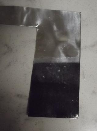 I couldn't
help but feel something more must be making the
low current drive. I took a small sheet of zinc and connected it in
place of the zinc electrode. Charging current jumped from ~30mA to
~100. If that was faster charging, great, but the whole thing didn't
make sense to me. Metallic zinc is supposed to be the charged form. But
the shiny metal turned black, and it wouldn't hold voltage or drive a
load without charging. So if somehow it was fully discharged,
the high charge current was probably explained. I thought it would be a
quick test - I didn't want to charge the piece of zinc for even an
hour, potentially disrupting something else, to see if the cell had
more drive current capacity. Also, I couldn't find any zinc compounds
that are black. Zinc oxide and zinc hydride are both white. What was
that black coating?
I couldn't
help but feel something more must be making the
low current drive. I took a small sheet of zinc and connected it in
place of the zinc electrode. Charging current jumped from ~30mA to
~100. If that was faster charging, great, but the whole thing didn't
make sense to me. Metallic zinc is supposed to be the charged form. But
the shiny metal turned black, and it wouldn't hold voltage or drive a
load without charging. So if somehow it was fully discharged,
the high charge current was probably explained. I thought it would be a
quick test - I didn't want to charge the piece of zinc for even an
hour, potentially disrupting something else, to see if the cell had
more drive current capacity. Also, I couldn't find any zinc compounds
that are black. Zinc oxide and zinc hydride are both white. What was
that black coating?
I decided to charge for 10 or 15 minutes anyway and put it
back in. Soapy bubbles after a bit indicated that the zinc was probably
interacting with the soapy gel. Currents driving loads seemed a little
lower than with the regular zincode, so I put it back to normal. But it
was a small piece of solid zinc, not a proper electrode. So I still
don't really know for sure where the low current problem comes from.
[26th] It finally occurred to me that
while I had picked potassium
chloride as an electrolyte long ago, it might not be optimum. I had
wanted to use a mildly alkaline environment, but the copper
oxyhydroxide/zinc seemed to be working well at neutral pH. The guy
making copper hydroxide had got beautiful sky blue product at high
currents with sodium nitrate. I used magnesium sulfate and made mixed
copper hydroxides. I had heard of the nitrate/nitrite shuffle
discharging battery cells, but those were alkaline batteries. I
started thinking that sodium nitrate might be a very good bet for an
electrolyte with higher current capacity.
Westlab hasn't replied to my application for an account
for Turquoise Energy Ltd. I decided I would have to try making it from
nitric acid and sodium hydroxide. I found something on youtube about
making it from the acid and sodium bicarbonate. That sounded more
gentle and I did that, making about 25 grams of NaNO3. I replaced the
electrolyte in the cell (diluting out the KCl in the 'trodes) and found
it to be a little weaker rather than stronger. Oh well, nothing
ventured nothing gained. I dumped it and went back to the original salt
solution. I can still use the sodium nitrate for making Cu(OH)2 from
copper.
I also saw a way shown to make NaNO3 from "instant cold
packs" (which are "calcium ammonium nitrate") and (again) sodium
bicarbonate. There was another on turning nitrogen from ammonia (NH3)
into that of nitrate (NO3), but it was more involved. I ordered and got
some NaNO3 from Sigma Alderich, where Turquoise Energy already has an
account.
In the evening running another load test, I had the
thought that 50 Ω was the heaviest load that didn't draw the voltage
down too far, yielding around 1.15V. But it charged at 1.5-1.6 volts
and when disconnected the open circuit voltage rose over 1.3V? What
about lighter loads? I tried 100 Ω and the voltage rose to 1.239V, at
180 Ω it was 1.277V, and at 560 Ω it was 1.310V. The open circuit
voltage was about 1.326V.
So CuZn isn't really a "1.1 volt" cell - it should
probably be rated as a "1.2 volt" cell, but presently with really poor
current capacity. Since the cell is pretty much charged, that's taking
into account that voltages get lower as the cell discharges, so I won't
say "1.3 volts". But it also depends how far down one wants to
discharge. As CuOOH [III] => Cu(OH)2 [II] => CuOH [I]=> Cu
[0], the voltage lowers around 100mV per change, so if there's enough
zinc on the minus side, one can certainly run it down to well under a
volt before it actually dies.
And now back to my perennial question: Why is the current
capacity so low? If it can only draw a milliamp or two or three per
square centimeter of separator with good voltage instead of ten or
twenty or thirty, a cell with any current drive is going to have to
have an awful lot of electrode surface area. That Is the choice if I
can't figure out how to improve it.
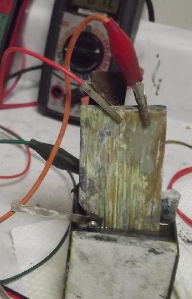 Hmm, weren't
the cupro-nickel sheets doing a lot better
than the powder in a box? I took one from the flat cell with lots of
nice green on it, folded it in half and stuck it in, using the box
electrode as a spacer and adding some electrolyte to fill it again.
Sure enough! Charging current started around 100mA. It drove even the
10 Ω load at over 1.0 volt. Soon short circuit current was double what
it had been, at 430mA.
Hmm, weren't
the cupro-nickel sheets doing a lot better
than the powder in a box? I took one from the flat cell with lots of
nice green on it, folded it in half and stuck it in, using the box
electrode as a spacer and adding some electrolyte to fill it again.
Sure enough! Charging current started around 100mA. It drove even the
10 Ω load at over 1.0 volt. Soon short circuit current was double what
it had been, at 430mA.
I didn't want loose copper
hydroxides floating around the
cell so I pulled it out again and reconnected the original electrode.
It started charging at 50mA and had better drive currents than before.
What? It was an alligator clip test leed. I had changed it in the
process and the new one was better! It still wasn't as good as the
piece of CuNi. But even the short circuit current was up to 280mA, and
in measuring that I bypassed all the test leed except those in the
meter itself.
What could I do better? Changing the parchment paper for
coffee filter paper had shown that electrolyte needed more room to flow
than I had assumed. For one thing I had overstuffed the electrode box
when I filled it, making the 'trode both too thick and, I think,
scrunching the material down too much, leaving not enough space
for good electrolyte flow. And fatter electrodes normally have lower
current capacity. Second, perhaps the box itself had too few 3D printed
"perforations" in it for good flow. I should try printing one that is
more "ethereal" on its interface surface. If that and the coffee filter
don't hold, maybe two layers of coffee filter? If currents were tripled
by these measures that would be at least half way to that "order of
magnitude" improvement it needs.
One thing of note is
that the performance seemed
consistent. When it was fully charged, it put out similar
currents/votlages at similar loads and one load test was much the same
as another, the biggest differences being in the initial minutes, which
depended on how long the cell had sat off charge before the test. If it
was freshly off charge, voltages would be higher but drop rapidly
whereas if it had been sitting idle they started lower but didn't drop
much with passing minutes.
Making Cu(OH)2
Hmm, the
sodium nitrate makes nice sky blue copper hydroxide,
and seemingly much faster than the magnesium sulfate or potassium
chloride, with the same electrical current. This bodes well for ability
to make small "production" quantities. Some blue was still floating
overnight, and in the morning I thought to stir it to degas it so I
could pour the water off. (Must save the liquid - it was the only
sodium
nitrate I had!)
Glue?
[27th] It occurred to me that I had originally taken on the ideas of
"sintered"
materials and crushed powder "briquettes" glued together from existing
alkaline battery literature and practices. But it seems to me that
amorphous powders that can shift inside the electrode as they change
form in charge and discharge should have superior cycle life (like, why
not forever?). And
without a binder, "briquettes" either crumble spontaneously or are
terribly fragile to handle.
But solid squares of material are much easier to assemble
into an electrode than trying to stuff in powder, especially through
the edge of a thin box as I've been doing in the latest form. So what
if one wetted the powder with a solution of water soluble gum arabic
and then formed it into a briquette? Once the 'trode or the whole cell
was assembled, the gum could be dissolved out. (Tada!)
New Design Cu+++ Electrode
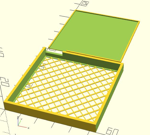 In the morning I started writing about how I might
construct a "production" battery (below) and as I did so I designed a
new "face down" electrode box. I got excited by that idea and created
the design in OpenSCad, then 3D printed it.
In the morning I started writing about how I might
construct a "production" battery (below) and as I did so I designed a
new "face down" electrode box. I got excited by that idea and created
the design in OpenSCad, then 3D printed it.
Late in the evening I was able to get back to it. I took
apart the previous box with the Cu material that wasn't made more
conductive with graphite and added 5% graphite. It was still slightly
damp from being in the cell and I mixed it and made it into a
briquette, simply stepping on the die to compact the material. Copper
hydroxides don't seem to need the high pressures of nickel hydroxide or
iron oxide. It held together well enough to put it into the box without
issue. (even without gum arabic) The box (with the coffee filter?)
weighed 4.9g empty and 20.1 filled, so the active material was 15.2g
including .75g of graphite. Perhaps 8 amp-hours worth at 2 electrons
per Cu.
I set the same CuNi current collector on the briquette and
the box back over all. Then I dripped methylene chloride (MC) into the
seam and pressed the back on. I had given it a bit of a "lip" for the
MC to adhere to. Then it just needed a bit of heat glue around the
terminal. This assembly was much easier than stuffing powder down a
thin crack on the top edge.
I removed the other trode
from the cell and put the new
one in. It was barely above 1 volt and wouldn't run a load. Why is it
that whatever state the material was in when it left the cell, the same
material starts out pretty much discharged when it re-enters the cell?
Anyway I could see it was going to be an improvement when the charging
started out at 115mA and only slowly (30'?) crept down through the
100s, 90s, 80s, 70s and into the 60s. At that point a quick test showed
over 1.1 volts driving a 20 Ω load - the highest so far. A short
circuit supplied over 400mA - 16mA per square centimeter of interface.
And that with a dead short. At least (and at last) performance had
entered into the right order of magnitude! It was as good as the CuNi
sheet and would probably charge to better in a few hours. [Note: With
charging it held a charge longer, but the short term currents didn't go
up.]
[27th]
22:58 54mA; 1.314V; reduced 1.6V to 1.5V charge voltage
00:20 28mA; 1.329V
[28th]
10:12 13mA; 1.355V (still @ 1.5V charge) - ran some short but heavy
loads
15:10 20mA; 1.352V
17:50 16mA; 1.351V
[28th] The new copperode had better current drive than any previous,
but it was still way under commercial cells and further improvement
would be highly desirable. What could I change? I could make the
"basket weave" traces thinner - one "pixel" wide (.4mm) instead of two
or three. But they were already less than stiff. I could print "finer"
quality, traces .2mm thick instead of .3mm so the paper would only be
.4mm from the face instead of .6mm. Or, the front face .8 wide but the
second, the opposite direction and touching the separator paper, .4mm.
Maybe both those things. And maybe print the inner threads a little
more densly to make up for the thinness. And maybe make the "lip"
around the edge of the paper a little thinner.
I made the changes and told the slicer program ".2mm
layers". Once again, incremental improvements. Hopefully it will get up
to maybe 20ma/sq.cm, and I may have to content myself with that for
now. But when I printed it, the program didn't print the one pixel wide
second layer of weave! I guess it said "too thin to bother with!" I
changed it from ".4" to ".5" (mm). Then it printed the bead, but laid
down two traces instead of one! Double or nothing! Well, they were
still a bit skinnier than the .8mm wide ones. Two more tweaks - I made
the skinny ones .4mm tall; the lid still fit too tight - and I figured
it was good. Making the skinny weave taller added a bit of strength
while holding the coffee filter paper away from the wider layer,
hopefully making less blockage.
And (how could I forget?) there's thickness. Thinner
trodes have more current capacity, and I've been making mine pretty
thick. Maybe I'll try putting fewer grams of powder into the next box
instead of stuffing it full or bulging?
I had 25.75g of Cu(OH)2. Instead of 3% or 5% graphite
powder, I added 7% - 1.8g. The Copper hydrixide was still damp. I
thought slightly, but it was a pretty smooth cream when I mixed it.
With the graphite the bright blue CuOHOH turned dark blue-grey and it
was still cream. I smeared just 10.1g of it into the box. The back of
the box was considerably recessed, so the electrode substance was only
2-3mm thick. I glued the back on. Then heat glued around the terminal
slot. Then I remembered to drill a hole in the terminal tab of the new
current collector. (I hope the new "untreated" CuNi CC doesn't cause
trouble.)
Next I soaked it to dilute out the NaNO3 still in it.
(Then added the contents of the soaking tray to my "hard to get" NaNO3
solution.) First impressions (after charge rose from 5mA to 25,
probably as it got electrolyte) were that it was probably better than
the last one. The voltages at different loads were a little higher (at
least for a few seconds since it was hardly starting to charge). And
short circuit current was 480mA. That's almost 20mA/sq.cm. I was hoping
for a little better with the thinner electrode.
Then I accidently left it running in the evening until it
was down to .7xx V.
[28th] @ 1.6V charge
21:55 30mA; 1.391V
[29th]
09:17 14mA; 1.407V
12:42 12mA; 1.442V
21:40 12mA; 1.475V
[29th] In the morning although the charge had slowed, drive currents
were down - only 330mA shorted, and various loads didn't seem quite as
good. Because I ran it down too far? Because I used a new still
"silvery" CuNi current collector? Hoping more charging will bring it
back up. It did seem to help, but after some hours it still wasn't
100%. I suspect the current collector. Hmm... I suspect the two
electrodes are touching each other. I backed them off a bit and
voltages went up substantially. (Why charging current didn't get higher
I'm not sure.)
Voltages & currents after 5 seconds (16:00 PM, 29th)
Note that resistances in the test leeds, alligator clips and switch
account for discrepancies in figures. Lighter loads were run before
heavier ones. Short circuit was measured with a separate meter directly
between battery terminals.
Ohms Ω
|
Volts
|
Milliamps
|
charge current
before starting
open circuit volts
after 30 seconds
|
1.432
|
-14
|
50
|
1.215
|
23
|
20
|
1.107
|
47
|
10
|
.979
|
85
|
5
|
.811
|
138
|
0.1
|
.148
|
361
|
short
circuit
|
|
430
|
How might current drive be improved? I think the current
drive to aim for is probably around 50mA/sq.cm. It would seem the
currents are at best 1/3 of that.
With the need to keep the zinc from forming dendrites I
don't think the watercolor paper or the cellophane can be eliminated,
and anyway the "+" side seems to be the more limiting factor... or is
it? At this point it has been significantly improved.
* maybe the current collector is less than optimum? I want monel!
* could the "+" powder mix be improved? Would putting in orange CuOH be
better than starting with blue Cu(OH)2?, when they both presumably
charge to CuOOH anyway.
* try different amounts of compaction of the Cu powders?
[30th] The newest electrode, which had performed "best one so far" at
first, seemed weaker and weaker. I finally took it out and put the
previous one back in. On inspection the back had come unglued. Since it
was recessed inside the box to make it thinner, it pushed out easily.
Things had doubtless loosened up inside and the connectivity within the
powder had become poor. That explained the low charging current as
well. I was relieved to find an obvious explanation - and that the zinc
electrode is still fine after all this time! The other electrode
started charging at over 100mA and soon was performing well.
So back to the main topic, "How can current drive be
improved?" It's half way there now, half the "order of magnitude"
better. No one improvement has done it but little things. But I'm out
of the really promising ideas.
I read in one research report that they got zinc-air up to
200mA/sq.cm, but that's with free oxygen and without gelling the zinc
to prevent dendrites. I think a realistic current drive to aim for with
these cells is probably around 50mA/sq.cm short circuit current. (That
would be 50 mA/sq.cm * 25 sq.cm = 1250 mA. It would seem they are at
best about 1/3 of that.
With the need to keep the zinc from forming dendrites I
don't think the watercolor paper or the cellophane can be eliminated,
and anyway the "+" side seems to be the more limiting factor... or is
it? At this point it has been significantly improved.
* maybe the current collector is less than optimum? I want monel!
* try different amounts of compaction of the Cu powders?
* could the "+" powder mix be improved? Would putting in orange CuOH be
better than starting with blue Cu(OH)2?, when they both presumably
charge to CuOOH anyway.
Wait! my previous discovery... the thing to try is to mix the Cu(OH)2
and the graphite and dissolve them in acetone to form epitaxial
crystals of both substances, mixed at the molecular level instead of
separate grains of each. I bet that would do it!
I mixed the rest of the Cu(OH)2 powder/graphite in acetone
in the afternoon and dried it in a few hours, spreading it out and
setting it on the woodstove. By later evening I put it in the box that
had come unglued anyway. It started charging around 90mA and by 23:59,
with driving an occasional load to see what it was doing, it was still
running 60-70mA. It wasn't driving especially well. I attribute that to
needing a lot more charging and (hopefully) better internal
connectivity meaning the whole trode had to charge up some before
anything would look very impressive. The high charging currents were
encouraging.
[31st] It wasn't performing any better in the morning. I think I made a
mistake putting the powder in before the acetone was really gone. Also
the current collector was loose, so at least when not wedged into the
cell there was no compaction. I pulled it out and set it on the
woodstove. Maybe I could belatedly be sure the acetone was all gone?
Three hours later I tried again. I put a couple of pieces
of sponge rubber weatherstripping on the back so that (with spacers
behind it) it was being held in some compression. This time it started
out weak again, but improved with charging dropping to 50mA over five
hours. By then it was putting out voltages and currents almost matching
the table of the 29th, above - better with 50 Ω, weaker at high
currents.
[February 1st to 4th] Performance continued to deteriorate instead of
strengthen. It all seemed very arbitrary and temperamental. On the 4th
I think I have an solution: Raising the charge voltage to 1.6 or 1.8
volts accomplished some desired initial changes, "forming" the
electrode and the current collector. But it's too high for regular
charging. I suspect it is forming copper oxide instead of copper
hydroxide, and it may be forming compounds with the electrolyte such as
KCu(OH)3 and CuClOH (or?), and that these things just don't perform.
Copper oxides apparently don't convert to hydroxides, and compounds
involving the electrolyte might dilute it too much. The next thing I'm
trying is (1) completely discharge the cell (meaning, the electrode) to
"reset" the oxides/hydroxides to copper. (2) Recharge at 1.5 volts or
less so [hopefully] only pure copper hydroxides form, the desired CuOH,
Cu(OH)2 and CuOOH. The currents from charging at this voltage are low
and it's taking a long time, but presumably it should charge up
"normally".
[Feb. 5th, 6th] I tried bleaching the electrode ina jar lid of water
with a tablespoon of bleach, but nothing seemed to help. I stuck the
cupro-nickel sheet back in as a "+" electrode and got much better
results again. Maybe it had something to do with the nickel after all?
I decided that after thinking I had everything working,
and then it deteriorated with cycling, I needed a modified approach.
What would happen if I mixed copper hydroxide and nickel hydroxide and
made a mixed nickel-copper oxide, the way I had been doing
nickel-manganese oxides previously except only charge them to
copper hydroxides voltages rather than nickel oxyhydroxide?
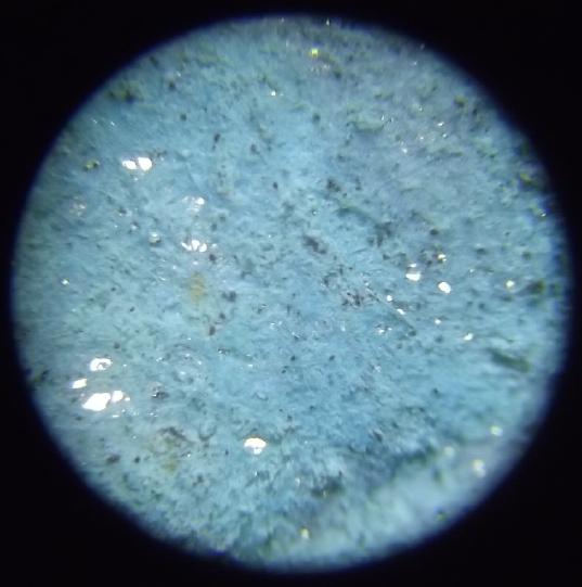 I must leave
further experiments for February, but of special note I have found
this: examining a used coffee filter from an electrode with the
microscope, it was encrusted with Ni(OH)2, but there were a few holes
(white from light behind) where powder might have been getting through.
I must leave
further experiments for February, but of special note I have found
this: examining a used coffee filter from an electrode with the
microscope, it was encrusted with Ni(OH)2, but there were a few holes
(white from light behind) where powder might have been getting through.
And later I found the art paper covering the zinc side had
absorbed a lot of fine copper substances. I figure it was probably
rather clogged, and that that might well account for the deteriorating
performances I have been getting rather than any chemical cause.
A Design for a Manufactured
CuNi-Zn Battery?
As the month went on I had various morfing ideas on how to produce
cells or their components. Here's where I ended up.
I decided to
start with the electrode size of the
compactor I already had made, 50 by 50 mm, and "stack" multiple
electrodes face to face within the cell. The cells then would be about
53mm wide on
the inside, and perhaps 70mm tall, to allow for a good water reservoir
and spot welded interconnections between like electrodes. The ends
would be thick ABS plastic to hold the cell from bulging. (1/4") The
sides would also be thick enough to glue to the edges of. (3/16") The
top and bottom could be thin. (1/16")
The length of the cell would depend on the number of
electrodes and their thickness. (This first one is only 25mm "long" for
just one double trode and two end ones; a test cell. The sides are thin
instead of top and bottom.)
I would keep
the electrode boxes for the copper side, but
make them on the flat with an open face (printed on the bottom) instead
of standing up with only an open edge to fill into. To make the faces
more open, run just one layer (.2mm) of thin diagonal stripes with
spaces between them in one direction, then on the next two layers, open
diagonal stripes in the opposite direction. This should serve to keep
the coffee filter paper in place with the active powder pressing
against it, without blocking much electrolyte.
The top face would be the same "weave", sized to fit just
inside the edge as this intended flat cell box I made a while back. The
top is glued on with methylene chloride or ABS cement.
For single thickness end electrodes (shown), only
one face need be open. After designing it I made a couple of variants
of this until everything fit well.
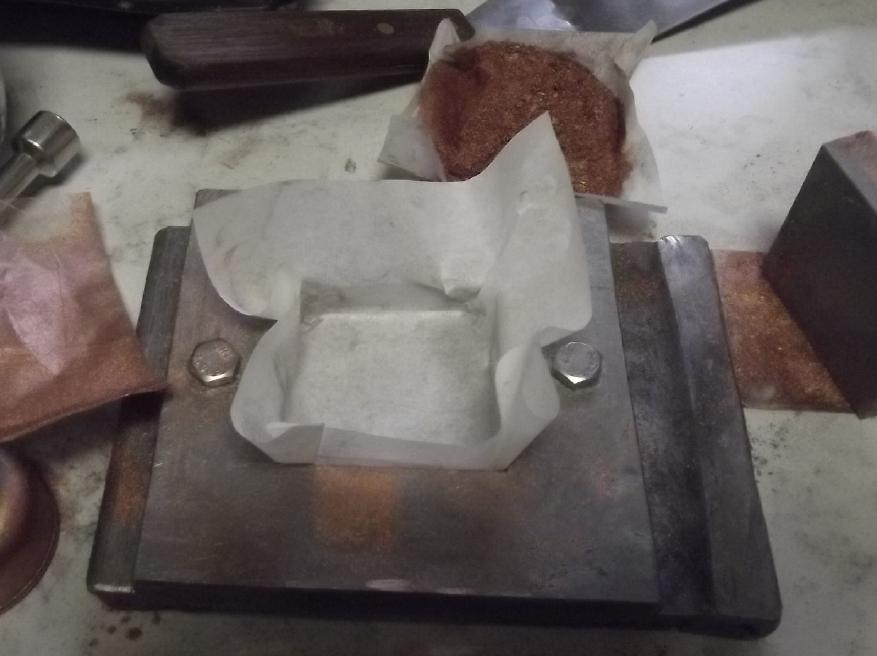 For the zinc side there is no outer box. I think I should use the
compactor. In similar manner to the illustration, wet the toluene
treated watercolor paper so it will form and not rip, put the (first)
doped cellophane sheet down, and press about 5mm thickness of zinc into
it. I've found that extreme pressure isn't necessary. On top of that
goes the copper foil current collector with terminal tab. Perforated
copper foil or maybe expanded copper mesh would be best, especially for
double face trodes. If it's a single face end electrode the paper is
then folded up over top. If it's a double a [previously made] square of
zinc powder is placed on top of the current collector, then the other
cellophane, and then the paper is folded up to cover it. (Probably a
bit of glue or something to hold the paper in place?)
For the zinc side there is no outer box. I think I should use the
compactor. In similar manner to the illustration, wet the toluene
treated watercolor paper so it will form and not rip, put the (first)
doped cellophane sheet down, and press about 5mm thickness of zinc into
it. I've found that extreme pressure isn't necessary. On top of that
goes the copper foil current collector with terminal tab. Perforated
copper foil or maybe expanded copper mesh would be best, especially for
double face trodes. If it's a single face end electrode the paper is
then folded up over top. If it's a double a [previously made] square of
zinc powder is placed on top of the current collector, then the other
cellophane, and then the paper is folded up to cover it. (Probably a
bit of glue or something to hold the paper in place?)
This is then soaked for an hour in SDBS before insertion
into the cell.
have a plan now for how to make cells with high energy and currents
that should continue working well. Without doing a detailed forecast, a
heavy box something like 3 by 6 inches by 3 inches tall (not counting
terminals) should hold hundreds of actual amp-hours. The plan isn't the
most sophisticated way or the most economical at large scale, but it
should work at small scales. If the top is screwed on (not glued) it is
also highly
amenable to maintenance or modification should those be needed or
desired. A short can be repaired or a bad electrode replaced.
The monel/CuNi electrodes would be quite like Edison's
plates: perforated sheets of about 28 gauge CuNi formed into 6mm thick
"pockets" packed with fine monel/CuNi powder and then crimped or welded
shut on all sides and riveted (CuNi or plastic) at middle points so
they can't bulge. Connection tabs will be integral to one of the
perforated sheets or welded to it. This is better than Edison's in that
the CuNi sheets are also the active material, not just extra weight.
Designs for the zinc are more flexible. I'm thinking
similar pockets maybe 5mm thick (inside) of perforated plastic (3D
printed?), with a perforated sheet of copper foil in the middle, again
having a terminal of copper extended or welded to it. The doped
parchment paper would go inside around the edges with the whole soaked
in SDBS for an hour.
These individual electrodes would be packed alternately
into trays with toluene treated papers between to isolate them, the
trays holding not much excess water and lids screwed or glued onto
them, with a screw-on cap for filling and a tiny air hole to release
pressure.
This would be "manufacturing" and there are hurdles to it
at any scale - even "prototyping" scale. The CuNi sheets are hard and
not at all easy to perforate. The pin frogs I was using for thin foil,
graphite gasket or plastic are totally inadequate. Nails are hardly
sufficient. Any anyway tiny, closely spaced holes are best. Then there
has to be some piece of equipment to press the perforated sheets
together and crimp (or weld) and rivet them with the CuNi powder being
compacted inside. Molded case parts will be required. (One thing I can
and should buy ready-made is a good tack welder for copper &
CuNi/monel.)
Electricity
Generation
My Solar Power System
The Usual Daily/Monthly/Yearly Log of Solar
Power Generated [and grid power consumed]
(All times are in PST: clock 48 minutes ahead of local sun
time, not
PDT which
is an hour and 48 minutes ahead. (DC) battery system power output
readings are reset to zero
daily (often just for LED lights, occasionally used with other loads:
Chevy Sprint electric car, inverters in power outages or other 36V
loads), while the
grid tied readings are cumulative.)
Daily Figures
Notes: House Main
meter (6 digits) accumulates. DC meter now
accumulates until [before] it loses precision (9.999 WH => 0010
KWH), then is
reset. House East and Cabin meters (4
digits) are reset to 0 when they get near 99.99 (which goes to "100.0")
- owing to loss of second decimal precision.
Km = Nissan Leaf electric car drove distance, then car was charged.
New Order of Daily Solar Readings (Beginning May 2022):
Date House, House, House, Cabin => Total KWH Solar [Notable
power
Uses (EV); Grid power meter@time] Sky/weather
Main
DC East
(carport)
December
31st 884.71, 5.46, 49.57, 31.22 = > .92 [11959@17:00]
January 2024
01st 885.06, 5.51, 49.70, 31.38 => .69 [11980@17:00]
02d 885.18, 5.59, 49.78, 31.50 => .40 [12007@17:00]
03rd 885.49, 5.65, 49.88, 31.69 => .66 [12032@17:00;
55Km]
04th 887.45, 5.73, 51.18, 32.49 => 4.14 [55Km; 12063@17:00]
05th 887.83, 5.84, 51.35, 32.75 => .92 [90Km;
12097@16:30]
06th 890.62, 6.01, 52.81, 34.25 => 5.85 [60Km; 12137@22:00; 50Km]
Sunshine!
07th 891.02, 6.13, 53.02, 34.52 => 1.00 [12164@17:00]
08th 891.17, 6.17, 53.09, 34.62 => .36 [12191@16:30]
09th 892.22, 6.24, 53.55, 35.23 => 2.19 [55Km; 12224@17:00]
10th 895.38, 6.28, 55.04, 36.85 => 6.31 [12246@17:00]
11th 897.64, 6.32, 56.46, 37.90 => 4.77 [55Km; 12275@17:30] -9°
12th 898.46, 6.41, 56.83, 38.34 => 1.72 [12305@16:30] -6°
13th 898.54, 6.51, 56.96, 38.38 => .35 [55Km;
12353@22:00; 55Km] -2°
14th 900.25, 6.84, 57.92, 39.36 => 3.98 [12376@17:00] Sunny but cold
anyway -1°
15th 900.96, 7.07, 58.28, 39.80 => 1.74 [12403@17:00] +3°(yay!)
16th 901.22, 7.18, 58.44, 40.01 => .74 [12434@16:30]
17th 904.30, 7.56, 59.97, 41.83 => 6.81 [10Km; 12463@17:30]
18th 904.62, 7.69, 60.12, 42.10 => .87 [12484@17:00]
19th 904.85, 7.80, 60.22, 42.30 => .54 [90Km;
12521@17:30]
20th 905.18, 7.94, 60.36, 42.56 => .89 [105Km;
12574@23:30] Holy Bleep
53KWH! I put heat on in the garage to work in there for 3 hours!
21th 905.37, 8.05, 60.46, 42.61 => .45 [12590@17:30]
22th 906.39, 8.14, 60.94, 42.97 => 1.95 [12616@17:30]
23th 907.54, 8.19, 61.77, 43.07 => 2.13 [55Km; 12643@17:30]
24th 908.00, 8.23, 61.90, 43.28 => .84 [55Km; 12672@17:00]
25th 911.56, 8.27, 63.69, 45.08 => 7.19 [12697@17:30] Wow, Real
sunshine!
26th 912.90, 8.33, 64.42, 45.86 => 2.91 [55Km; 12710@17:30]
27th 913.33, 8.40, 64.56, 46.08 => .80 [55Km;
12751@24:30] Where did the
sunshine go?
28th 913.61, 8.44, 64.66, 46.23 => .57 [10Km;
12778@20:00]
29th 915.35, 8.51, 65.42, 47.14 => 3.48 [55Km; 12800@18:00]
30th Double OOPS! (and right at month end yet!) (prorated 1.74 as .74,
.05, .50, .45)
31st (prorated 1.73 as .73, .04, .50, .45) [50Km; 12868
(prorated)]
February
01st 918.76, 8.72, 66.84, 48.74 => (prorated 1.73 as .73, .04, .50,
.45) 5.20 [12873@18:30]
02d 922.59, 8.87, 68.91, 49.92 => [12895@21:30]
03rd 925.34, 8.94, 70.90, 51.80 => [55km; 12931@21:00; 50Km]
04th 929.18, 9.03, 73.09, 53.90 => [12953@18:00]
05th 932.04, 9.08, 74.63, 55.32 => [12980@17:30]
06th
Chart of daily KWH from solar panels.
(Compare January 2024
(left) with December 2023 & with January 2023.)
Days of
__ KWH
|
January
2024
(18 C's)
|
December 2023
(18 C's)
|
January 2023
(18 collectors)
|
0.xx
|
14
|
11
|
5
|
1.xx
|
6
|
9
|
8
|
2.xx
|
3
|
2
|
7
|
3.xx
|
2
|
6
|
2
|
4.xx
|
2
|
2
|
3
|
5.xx
|
1
|
1
|
2
|
6.xx
|
2
|
|
|
7.xx
|
1
|
|
2
|
8.xx
|
|
|
2
|
Total KWH
for month
|
68.18
|
57.93 |
93.79 |
Km Driven
on Electricity
|
1117.8 Km
(160KWH?)
|
771.8
(110KWH?) |
811.9 Km
(130 KWH?) |
Things Noted - January 2024
* Cloudiest January ever? 14 days of less than 1 KWH made for
the whole day!
Monthly Summaries: Solar Generated KWH [& Power used from
grid KWH]
As these tables are getting long, I'm not repeating the log of monthly
reports. The reports for the first four full years (March 2019 to
February 2023) may be found in TE
News
#177,
February
2023.
2023 - (House roof, lawn + DC + Cabin + Carport, Pole) Solar
Jan KWH: 40.57 + 3.06 + 28.31 + 21.85 = 93.79 Solar [grid: 1163; car
(very rough estimates): 130]
Feb KWH: 59.19 + 2.70 + 38.10 + 32.47 = 132.46 Solar [grid: 1079; car:
110]
(Four years of solar!)
Mar KWH: 149.49 + 2.72 + 53.85 + 92.08 = 298.14 Solar
[grid: 981; car:
140]
Apr KWH: 176.57 + 2.71 + 121.21 + 108.34 = 408.83 [grid: 676; car: 160]
"Lawn" collectors moved to South
"Wall"
May KWH:266.04 + 2.04 + 194.13 + 180.31 = 642.52 [grid: 500; car: 175]
Jun KWH: 237.55 + 3.70 + 172.56 + 126.31 = 540.12 [grid: 464; car: 190]
July KWH:236.99 + 1.95 + 169.16 + 155.21 = 563.31 [grid: 343; car: 180]
Aug KWH:223.61 + 1.78 + 158.31 + 134.40 = 518.00 [grid: 305; car: 130]
Sep KWH:124.33 + 2.33 + 92.76 + 76.23 = 295.65 [grid:
501; car: 150]
Oct KWH: 94.26 + 2.70 + 55.01 + 56.11 =
208.08 [grid: 842; car: 170]
Nov KWH: 45.70 + 3.10 + 24.35 + 15.91
= 89.06 [grid: 760; car: 120]
Dec KWH: 28.96 + 2.43 + 15.58 + 10.96
= 57.93 [grid: 815; car: 110]
Jan KWH: 31.37 + 3.14 + 16.85 + 16.82
= 68.18 [grid: 909; car: 160]
Annual Totals
1. March 2019-Feb. 2020: 2196.15 KWH Solar [used 7927 KWH
from grid]
2. March 2020-Feb. 2021: 2069.82 KWH Solar [used 11294 KWH from grid]
(More electric heat - BR, Trailer & Perry's RV)
3. March 2021-Feb. 2022: 2063.05 KWH Solar [used 10977 KWH from grid]
4a. March 2022-August 2022: in (the best) 6 months, about 2725 KWH
solar - more than in any previous entire year!
4. March2022-Feb. 2023: 3793.37 KWH Solar [used 12038 KWH from grid]
Money Saved or Earned - @ 12¢ [All BC residential elec.
rate] ; @
50¢ [2018 cost of diesel fuel to BC Hydro] ; @ 1$ per KWH [actual
total
cost to BC Hydro
in 2022 according to an employee]:
1. 263.42$ ; 1097.58$ ; 2196.15$
2. 248.38$ ; 1034.91$ ; 2069.82$
3. 247.57$ ; 1031.53$ ; 2063.05$
4. 455.20$ ; 1896.69$ ; 3793.37$
It can be seen that the benefit to the society as a whole
on Haida Gwaii from solar power installations is much greater than the
cost savings to the individual user of electricity, thanks to the heavy
subsidization of our power
owing to the BC government policy of having the same power rate across
the entire province regardless of the cost of production. And it can be
insurance: With some
extra equipment and a battery, sufficient solar can deliver essential
power in
electrical outages however long. (Feb 28th 2023: And it's probably well
over 1$/KWH by now the way inflation of diesel fuel and other costs is
running.)
http://www.TurquoiseEnergy.com
Haida Gwaii, BC Canada