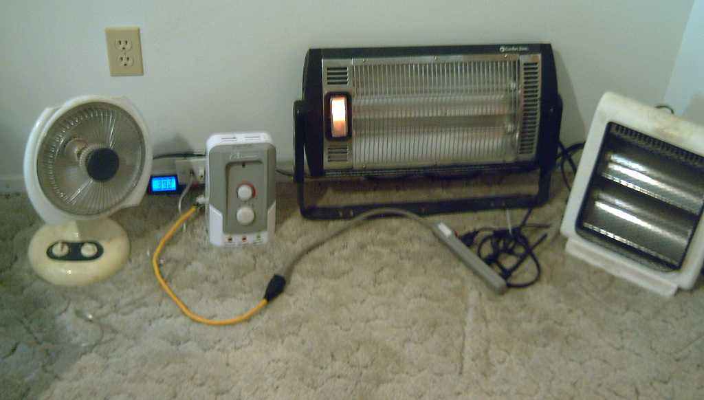
120V Heaters, extra low powered by 36V DC, plugged into a "thermostat box"
(via power bar & adapter plug cable)
 While on the
subject of DC power I'm using T-Plugs as the "standard" 36 V DC plugs
in lieu
of there being any practical alternative, but I do have a complaint.
The pins are too short, and they pull out or lose contact with the
socket too easily. They would be much better if they were even 10mm
long instead of 8.
While on the
subject of DC power I'm using T-Plugs as the "standard" 36 V DC plugs
in lieu
of there being any practical alternative, but I do have a complaint.
The pins are too short, and they pull out or lose contact with the
socket too easily. They would be much better if they were even 10mm
long instead of 8.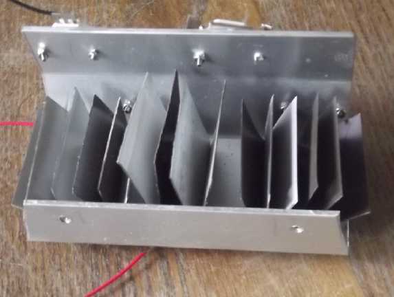 In thinking of a 36 volt upstairs ceiling light for the
cabin, I went to my long neglected drawer of LED things and found a
rather elaborate heatsink I had made long ago (2013?) to go with a
"mushroom"
light diffuser I had taken a fancy to. (Recall that back then LED
"regular" light "bulbs" were hardly available, much less the wide
variety of LED "bulbs" and light fixtures now on the market.) The
intent had been to bolt four 2.9 volt "Cree" LED emitters to it for a
12 volt light. Then Cree
emitters I had already used started giving me problems. They started
out as 2.9 volts, so four made 11.6 volts, and a resistor would limit
the current for 12 volts. But their characteristics changed - they
gradually started working
at 3 volts, then 3.1 or more, and while they still worked, the supply
voltage had to be raised and
raised to keep the light from becoming quite dim.
In thinking of a 36 volt upstairs ceiling light for the
cabin, I went to my long neglected drawer of LED things and found a
rather elaborate heatsink I had made long ago (2013?) to go with a
"mushroom"
light diffuser I had taken a fancy to. (Recall that back then LED
"regular" light "bulbs" were hardly available, much less the wide
variety of LED "bulbs" and light fixtures now on the market.) The
intent had been to bolt four 2.9 volt "Cree" LED emitters to it for a
12 volt light. Then Cree
emitters I had already used started giving me problems. They started
out as 2.9 volts, so four made 11.6 volts, and a resistor would limit
the current for 12 volts. But their characteristics changed - they
gradually started working
at 3 volts, then 3.1 or more, and while they still worked, the supply
voltage had to be raised and
raised to keep the light from becoming quite dim.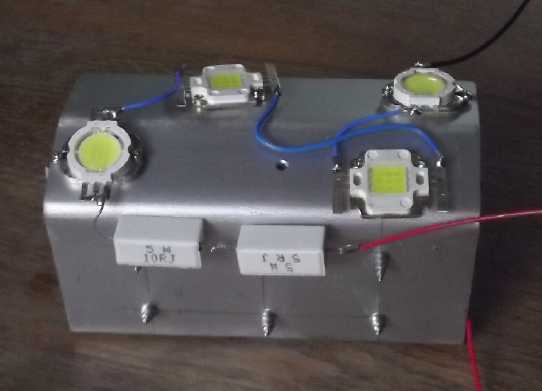 In the upshot,
I had all but finished the light, but never
did. Every detail was done except putting the emitters on and wiring
them up. And then
lovely commercial LED flat panel lights (among many other choices)
started becoming available. Now I thought, what emitters do I have left
in that box from those times? I found two sets of three 9-volt
emitters, 'square' and 'oval' in shape. (I think they're about 4000K
color temperature - greenish. Many might have gone lower
3000K(?), more yellow, for a bedroom, but I had these and in general I
do like 4000K. 5000 seems like a lot of blue to me.)
In the upshot,
I had all but finished the light, but never
did. Every detail was done except putting the emitters on and wiring
them up. And then
lovely commercial LED flat panel lights (among many other choices)
started becoming available. Now I thought, what emitters do I have left
in that box from those times? I found two sets of three 9-volt
emitters, 'square' and 'oval' in shape. (I think they're about 4000K
color temperature - greenish. Many might have gone lower
3000K(?), more yellow, for a bedroom, but I had these and in general I
do like 4000K. 5000 seems like a lot of blue to me.)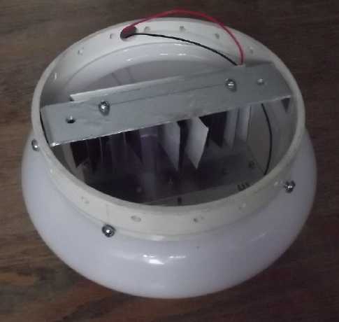

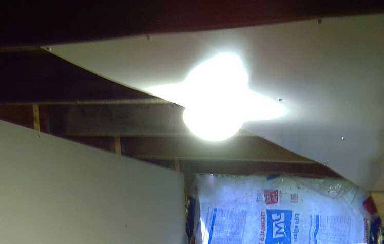 I mounted it
on the ceiling but
didn't get it wired until early June. I didn't use an electrical box at
the light, but just connected with T-Plugs inside the light itself,
tie-wrapped to the metal heatsink.
I mounted it
on the ceiling but
didn't get it wired until early June. I didn't use an electrical box at
the light, but just connected with T-Plugs inside the light itself,
tie-wrapped to the metal heatsink. I used #18 AWG speaker wire. I
have lots of house wire, but it just seemed like such total overkill
for a light fixture now that lights are LEDs. A 13 watt light is just
.333 amps at 39 volts. Without looking it up, I'm sure #18 wire is
rated for a least 5 amps. I drilled a small hole diagonally through the
center ridge 2 by 10 to get from the wall space into the ceiling space
- not something one would do with heavy wire. Having no "telephone
wire" cable stapler, I used ordinary paper staples at short intervals,
and I poked the wires through the screwdriver holes in the knockouts in
the light switch box, wrapping PVC tape around them to prevent
abrasion/shorts in case the edges were sharp.
I used #18 AWG speaker wire. I
have lots of house wire, but it just seemed like such total overkill
for a light fixture now that lights are LEDs. A 13 watt light is just
.333 amps at 39 volts. Without looking it up, I'm sure #18 wire is
rated for a least 5 amps. I drilled a small hole diagonally through the
center ridge 2 by 10 to get from the wall space into the ceiling space
- not something one would do with heavy wire. Having no "telephone
wire" cable stapler, I used ordinary paper staples at short intervals,
and I poked the wires through the screwdriver holes in the knockouts in
the light switch box, wrapping PVC tape around them to prevent
abrasion/shorts in case the edges were sharp. Over a year ago a wind blew over my insecurely secured 3 PV panel
"A-frame" mounting on the carport roof and one panel had bent and
broken. Then it fell when I tried to lower it off the roof and broke
some more. But testing the wires showed that it still worked so I
didn't discard it.
Over a year ago a wind blew over my insecurely secured 3 PV panel
"A-frame" mounting on the carport roof and one panel had bent and
broken. Then it fell when I tried to lower it off the roof and broke
some more. But testing the wires showed that it still worked so I
didn't discard it.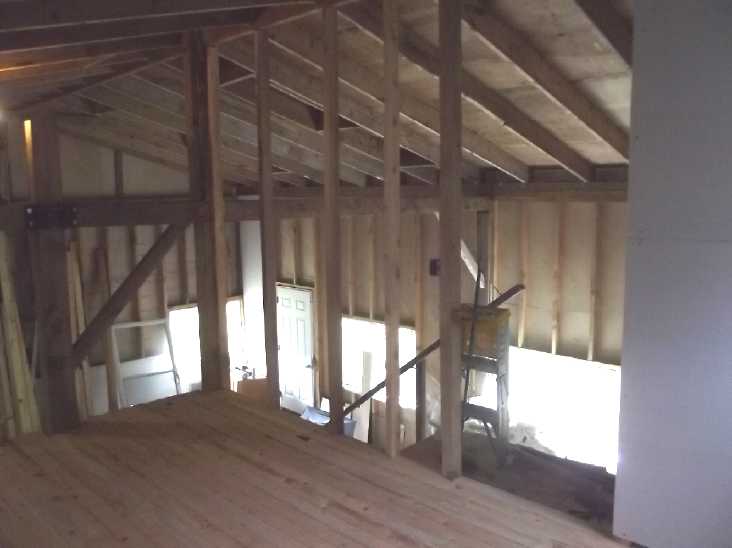 I put 2
by 3 studs from the edge of the floor up to the ridge board for a wall
frame. I only got half the gyproc up.
I put 2
by 3 studs from the edge of the floor up to the ridge board for a wall
frame. I only got half the gyproc up. I put the gyproc on half the wall, then I slid the insulation in above
the ceiling where the light is.
I put the gyproc on half the wall, then I slid the insulation in above
the ceiling where the light is.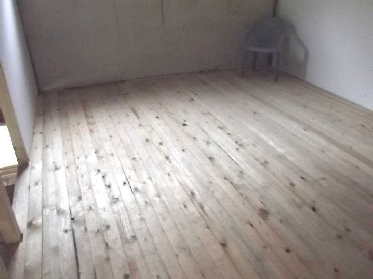 [16th] Now that it
was spring and
the wood would be drier, I glued down the rest of the
upstairs tongue & groove floor. Three boards per day. I finished
the last bits at the door opening on the 31st.
[16th] Now that it
was spring and
the wood would be drier, I glued down the rest of the
upstairs tongue & groove floor. Three boards per day. I finished
the last bits at the door opening on the 31st. Best "Faraday
cage"? The chicken yard. (The wire is probably grounded here and
there.) There in the front yard so nearly under the power lines my body
voltage measured around a volt, some places closer to two. Inside the
chicken yard with the door closed it was 15 to 20 millivolts, almost a
99 % reduction and surely in the "no tinnitus" range. The chickens
don't know how good they have it!
Best "Faraday
cage"? The chicken yard. (The wire is probably grounded here and
there.) There in the front yard so nearly under the power lines my body
voltage measured around a volt, some places closer to two. Inside the
chicken yard with the door closed it was 15 to 20 millivolts, almost a
99 % reduction and surely in the "no tinnitus" range. The chickens
don't know how good they have it!


 The insulation
wouldn't stay up between the 2 foot centers 2 by 8's. At the low wall I
started sliding it in on top of the ceiling sheets. That seemed to
work, but before doing the next sheet up, I decided to make the wall at
the side of the room. I would have to set the short step ladder
uncomfortably close to the edge. If something happened I could see
tumbling out of the upstairs down to the clutter of lumber below, which
would be bound to at least hurt a lot. So at some point I put 2 by 3
studs from the edge of the floor up to the ridge board for a wall
frame. They didn't quite line up with the ridge, so each one was a
custom fit at the top. (I didn't think to take a picture of the open
framework, but I only got half the gyproc up in May.) I put the
gyproc on half the wall, then I slid the insulation in above the
ceiling where the light is. (I did in fact stumble against the wall
once coming off the short stepladder. I like to think that if I had
done it without the wall up yet, I'd have positioned the ladder another
way. But the wall certainly made it much safer.)[16th] Now that it
was spring and
the wood would be drier, I started gluing gluing down the rest of the
upstairs tongue & groove floor. Three boards per day. I finished
the last bits at the door opening on the 31st.
The insulation
wouldn't stay up between the 2 foot centers 2 by 8's. At the low wall I
started sliding it in on top of the ceiling sheets. That seemed to
work, but before doing the next sheet up, I decided to make the wall at
the side of the room. I would have to set the short step ladder
uncomfortably close to the edge. If something happened I could see
tumbling out of the upstairs down to the clutter of lumber below, which
would be bound to at least hurt a lot. So at some point I put 2 by 3
studs from the edge of the floor up to the ridge board for a wall
frame. They didn't quite line up with the ridge, so each one was a
custom fit at the top. (I didn't think to take a picture of the open
framework, but I only got half the gyproc up in May.) I put the
gyproc on half the wall, then I slid the insulation in above the
ceiling where the light is. (I did in fact stumble against the wall
once coming off the short stepladder. I like to think that if I had
done it without the wall up yet, I'd have positioned the ladder another
way. But the wall certainly made it much safer.)[16th] Now that it
was spring and
the wood would be drier, I started gluing gluing down the rest of the
upstairs tongue & groove floor. Three boards per day. I finished
the last bits at the door opening on the 31st.
 Then I gooped
up the edges of the back cover with ABS
cement and stuck it on. I added some more along the seam on all four
sides with a small screwdriver. I gave it a while to dry and was about
to put it in the cell when I remembered that I hadn't gooped up the
terminal slit. So I did that. If the zinc in the electrode is going to
dissolve into "supersaturated" zincate liquid as it discharges and stay
that way until it is recharged, it is obviously vital that there be no
leaks - no way in and out of the zinc box or compartment except through
the treated separator sheet.
Then I gooped
up the edges of the back cover with ABS
cement and stuck it on. I added some more along the seam on all four
sides with a small screwdriver. I gave it a while to dry and was about
to put it in the cell when I remembered that I hadn't gooped up the
terminal slit. So I did that. If the zinc in the electrode is going to
dissolve into "supersaturated" zincate liquid as it discharges and stay
that way until it is recharged, it is obviously vital that there be no
leaks - no way in and out of the zinc box or compartment except through
the treated separator sheet. I
started by picking out a 3D printed tray. It seemed to
me that the zinc side had an advantage with the copper screen running
through it in three layers. The copper only had a solid (and rather too
thick) sheet of CuNi metal. What if I cut the sheet back and forth and
then expanded it out in the jewelers rolling mill? I found a piece that
with a long terminal tab and the right width, but it was only about 3/4
tall. If I stretched it it could be about right. I cut it into
connected strips with tinsnips, about 3-4mm wide. I ran it through the
rolling mile a few times until it was actually too tall for the space,
then I bent it at the joins to make 45° angles, so it went pretty
much front to back within the electrode space as well as covering the
50x50mm area.
I
started by picking out a 3D printed tray. It seemed to
me that the zinc side had an advantage with the copper screen running
through it in three layers. The copper only had a solid (and rather too
thick) sheet of CuNi metal. What if I cut the sheet back and forth and
then expanded it out in the jewelers rolling mill? I found a piece that
with a long terminal tab and the right width, but it was only about 3/4
tall. If I stretched it it could be about right. I cut it into
connected strips with tinsnips, about 3-4mm wide. I ran it through the
rolling mile a few times until it was actually too tall for the space,
then I bent it at the joins to make 45° angles, so it went pretty
much front to back within the electrode space as well as covering the
50x50mm area.
 [25th] I
soaked a separator paper in SDBS solution, then cut a piece of
1/16" ABS sheet for a back to the tray. I put the paper in behind the
plastic grill. When it's wet is the best time to fit it properly. Then
I looked for my previous instructions so I wouldn't forget any steps.
Which issue was that in again? I'm probably about ready to do a
"battery making manual" and keep it updated with whatever new is
learned.
[25th] I
soaked a separator paper in SDBS solution, then cut a piece of
1/16" ABS sheet for a back to the tray. I put the paper in behind the
plastic grill. When it's wet is the best time to fit it properly. Then
I looked for my previous instructions so I wouldn't forget any steps.
Which issue was that in again? I'm probably about ready to do a
"battery making manual" and keep it updated with whatever new is
learned.
 Now what? A whole new electrode, again, to try a different
powder mix on spec? It's well glued shut. But I had made the tray type
with no lip around the "basket weave" face. Perhaps I could snip it off
round the edges, pull off the separator paper, and thus access it from
the front, losing some interface surface to glue when putting it
together again?
Now what? A whole new electrode, again, to try a different
powder mix on spec? It's well glued shut. But I had made the tray type
with no lip around the "basket weave" face. Perhaps I could snip it off
round the edges, pull off the separator paper, and thus access it from
the front, losing some interface surface to glue when putting it
together again? [27th] I say!
The monel powder seems to have shaped it up marvelously. Charge
currents (at 1.6V) seem higher, and in a few minutes of charging the
voltage started drifting down from over 1.5V(!) instead of 1.3V. It
momentarily put out over 1.2V (over 110mA) into the 10 ohm load - the
highest ever. Hmm, and over 1.4V into 50 ohms! This suggests a copper
oxyhydroxide voltage of at least +.2V, which is about what I had
previously surmised. So far it's looking like the best battery I've
done. Once again, the question is how long it can do that once charged,
and will the discharge voltages keep gradually decreasing?
[27th] I say!
The monel powder seems to have shaped it up marvelously. Charge
currents (at 1.6V) seem higher, and in a few minutes of charging the
voltage started drifting down from over 1.5V(!) instead of 1.3V. It
momentarily put out over 1.2V (over 110mA) into the 10 ohm load - the
highest ever. Hmm, and over 1.4V into 50 ohms! This suggests a copper
oxyhydroxide voltage of at least +.2V, which is about what I had
previously surmised. So far it's looking like the best battery I've
done. Once again, the question is how long it can do that once charged,
and will the discharge voltages keep gradually decreasing? I grabbed a
piece of cupro-nickel. I wasn't just
sure what I might do. I squeezed it in the rolling mill, thinking to
make it long and fold it in half, and crimp the edges. Like the old
1890s designs. Then I annealed it and rolled again. It seemed thinner,
but it was just a bit short for a 50x50mm electrode box without
folding. Hmm... I
could use the other 3D printed tray with a solid bottom and the CuNi on
the front? Okay. Then I punched it full of holes with a hammer and
nail, one at a time. (Ug!)
I grabbed a
piece of cupro-nickel. I wasn't just
sure what I might do. I squeezed it in the rolling mill, thinking to
make it long and fold it in half, and crimp the edges. Like the old
1890s designs. Then I annealed it and rolled again. It seemed thinner,
but it was just a bit short for a 50x50mm electrode box without
folding. Hmm... I
could use the other 3D printed tray with a solid bottom and the CuNi on
the front? Okay. Then I punched it full of holes with a hammer and
nail, one at a time. (Ug!) The thin plastic tray back
would bulge, so I
cut a piece of 1/16"
ABS and put it inside to stiffen it. I added 20 wt% monel (but only a
tiny amount by
volume) to the Cu(OH)2 mix and used 5 grams.
The thin plastic tray back
would bulge, so I
cut a piece of 1/16"
ABS and put it inside to stiffen it. I added 20 wt% monel (but only a
tiny amount by
volume) to the Cu(OH)2 mix and used 5 grams. I
pressed it in and gooped
it shut with plenty of ABS cement, even tho the front was metal, not
ABS, I pressed it a bit in the hydraulic press then found some metal
pieces to fit and held it pressed with a C-clamp while the glue
hardened. A little powder puffed out the front through the nail holes.
That wouldn't do.
I
pressed it in and gooped
it shut with plenty of ABS cement, even tho the front was metal, not
ABS, I pressed it a bit in the hydraulic press then found some metal
pieces to fit and held it pressed with a C-clamp while the glue
hardened. A little powder puffed out the front through the nail holes.
That wouldn't do.
 I
pressed it in in front of the
perfed metal. I left it to dry on the woodstove warmer. Then I found a
piece of 3D printed "basketweave" and glued it on around the edges. I
still wasn't satisfied that the copper would stay compacted inside.
I
pressed it in in front of the
perfed metal. I left it to dry on the woodstove warmer. Then I found a
piece of 3D printed "basketweave" and glued it on around the edges. I
still wasn't satisfied that the copper would stay compacted inside. I thought
about this arrangement, which was so likely to
prove unsatisfactory if a lot of pressure needed to be kept on the Cu
materials. And then again about my earlier 3D printed "perforated"
plastic tubes. But they weren't very strong either - some had broken.
Then SUDDENLY I [thought I] knew how to perforate smooth plastic! Heat
a pin frog
(or similar metal perforator with pins), perhaps with an iron, and melt
the holes through! Why, in 16 years, have I never thought of this
before? With a strong perfed tube lined with a treated separator and
glued-on end plugs, one could hold the copper substance strongly in
compaction, with a simple monel wire or rod in the middle for a current
collector and terminal. (Say: for the terminal/current collector, a
screw shape. The 'trode would be made solid-filled, then the terminal
screwed into the middle. That would only improve compaction. Copper
& monel screws? Hah! Good luck!)
I thought
about this arrangement, which was so likely to
prove unsatisfactory if a lot of pressure needed to be kept on the Cu
materials. And then again about my earlier 3D printed "perforated"
plastic tubes. But they weren't very strong either - some had broken.
Then SUDDENLY I [thought I] knew how to perforate smooth plastic! Heat
a pin frog
(or similar metal perforator with pins), perhaps with an iron, and melt
the holes through! Why, in 16 years, have I never thought of this
before? With a strong perfed tube lined with a treated separator and
glued-on end plugs, one could hold the copper substance strongly in
compaction, with a simple monel wire or rod in the middle for a current
collector and terminal. (Say: for the terminal/current collector, a
screw shape. The 'trode would be made solid-filled, then the terminal
screwed into the middle. That would only improve compaction. Copper
& monel screws? Hah! Good luck!) I
got out 4 small nylon machine screws, drilled holes
right through the thickness, and tightened them on with stainless nuts.
(insofar as one can tighten nylon screws... I only used my fingers on
the nuts for fear of stripping them if I used a wrench. But metal
except monel in contact with the electrode would corrode away.)
I
got out 4 small nylon machine screws, drilled holes
right through the thickness, and tightened them on with stainless nuts.
(insofar as one can tighten nylon screws... I only used my fingers on
the nuts for fear of stripping them if I used a wrench. But metal
except monel in contact with the electrode would corrode away.) I took out the
plastic nuts and put in metal
ones. Then metal screws. They
wouldn't last, but at least I could torque them down! This time, 87mA.
Again not the huge improvement I had hoped for. But it stayed over 30mA
for a while, and the open circuit voltage didn't jump up over 1.2V but
instead was only about 1.0, probably meaning the charge was dispersing
into at least some of the powder better. I opened it again and torqued
down the screws pretty hard. Again there seemed to be slight
improvement. Compaction certainly seems to be what it needs. Now, time
to let it charge for a while and see what happens!
I took out the
plastic nuts and put in metal
ones. Then metal screws. They
wouldn't last, but at least I could torque them down! This time, 87mA.
Again not the huge improvement I had hoped for. But it stayed over 30mA
for a while, and the open circuit voltage didn't jump up over 1.2V but
instead was only about 1.0, probably meaning the charge was dispersing
into at least some of the powder better. I opened it again and torqued
down the screws pretty hard. Again there seemed to be slight
improvement. Compaction certainly seems to be what it needs. Now, time
to let it charge for a while and see what happens!
 I re-designed
the cylindrical electrode "pocket" (from
December) for 3D printing with .4mm layer height, which I hope should
work okay with ABS filament. Just 32mm tall for the first try, and to
fit in the same cell with the latest zinc.
I re-designed
the cylindrical electrode "pocket" (from
December) for 3D printing with .4mm layer height, which I hope should
work okay with ABS filament. Just 32mm tall for the first try, and to
fit in the same cell with the latest zinc. [31st] The print didn't
work on the first two tries, but after I
sprayed hair spray on the Kaptan tape, the third one stuck and printed.
I flexed it a bit and it snapped. Ug! I held it together and smeared
methylene chloride all over it. Hopefully that will hold, but I didn't
dare stress it very hard. (Maybe I should actually immerse them
in methylene chloride after they're printed? That would probably
strengthen them, but I'm almost out of it and I'm sure I'll have a hard
time getting more on this island.)
[31st] The print didn't
work on the first two tries, but after I
sprayed hair spray on the Kaptan tape, the third one stuck and printed.
I flexed it a bit and it snapped. Ug! I held it together and smeared
methylene chloride all over it. Hopefully that will hold, but I didn't
dare stress it very hard. (Maybe I should actually immerse them
in methylene chloride after they're printed? That would probably
strengthen them, but I'm almost out of it and I'm sure I'll have a hard
time getting more on this island.) [9th] The broken panel from
the carport roof winds of March, 14 months ago,
was still sitting on the lawn leaning against my porch. I had noted
that it still
worked, so I hadn't thrown it out. Now with the DC system seeming to
lose out against a grid tie
if it wasn't sunny, I checked. I couldn't remember about a cable that
ran from the porch into the garage at the solar equipment. It was once
the cable for the windplant. What after that? I had forgotten.
[9th] The broken panel from
the carport roof winds of March, 14 months ago,
was still sitting on the lawn leaning against my porch. I had noted
that it still
worked, so I hadn't thrown it out. Now with the DC system seeming to
lose out against a grid tie
if it wasn't sunny, I checked. I couldn't remember about a cable that
ran from the porch into the garage at the solar equipment. It was once
the cable for the windplant. What after that? I had forgotten.| Days of __ KWH |
May 2024 (18 Collectors) |
April 2024 (18 C's) |
May 2023 (18 C's) |
| 0.xx |
|||
| 1.xx |
|||
| 2.xx |
|||
| 3.xx |
|
||
| 4.xx |
|||
| 5.xx |
|
2 |
|
| 6.xx |
|
|
|
| 7.xx |
2 |
|
|
| 8.xx |
1 |
2 |
|
| 9.xx |
3 |
1 |
|
| 10.xx |
4 |
1 |
1 |
| 11.xx |
3 |
2 |
|
| 12.xx |
1 |
4 |
1 |
| 13.xx |
2 |
3 |
|
| 14.xx |
4 |
2 |
1 |
| 15.xx |
3 |
1 |
|
| 16.xx |
1 |
4 |
2 |
| 17.xx |
2 |
3 |
1 |
| 18.xx |
2 |
||
| 19.xx |
1 |
||
| 20.xx |
1 |
1 |
2 |
| 21.xx |
1 |
1 |
1 |
| 22.xx |
2 |
3 |
1 |
| 23.xx |
2 |
3 |
|
| 24.xx |
1 |
3 |
|
| 25.xx |
|
1 |
|
| 26.xx |
3 |
||
| 27.xx |
3 |
||
| 28.xx |
2 |
||
| 29.xx |
1 |
||
| Total KWH for month |
432.53 |
483.68 | 642.52 (all- time record!) |
| Km Driven on Electricity |
1091.9 (ODO 108799) (~~145KWH) |
1066.8 (~~140KWH) |
1207.4 Km (175 KWH?) |
| Date |
Used (watt-hours) from Battery |
Recharged (W-H) from solar |
| April 29th |
2650 |
2440 |
| 30 |
2647 |
2890 |
| May 1st |
2749 |
2990 |
| 2nd |
3059 (w. daytime heat) |
2790 |
| 3rd |
2080 |
1749 |
| 4th |
3606 (.w daytime heat) |
3136 |
| 5th |
1876 |
1702 (rain) |
| 6th |
1433 |
2227 |
| 7th |
2532 |
2601 |
| 8th |
1839 |
2228 |
| 9th |
2720 |
2377 |
| 10th |
2328 |
2301 |
| 11th |
1663 |
2484 |
| 12th |
2916 |
2020 (cloudy) |
| 13th |
2181 |
1903 (cloudy) |
| 14th |
1969 |
2183 (cloudy) |
| 15th Subtotals, May 1-15 |
1597 34,548 |
1606 (rain - still just 39.6V) 34,297 |
| 16th |
1491 |
2231 (catch-up) |
| 17th |
2642 all heaters, 280W |
2655 |
| 18th |
1801 |
2126 |
| 19th |
2526 all htrs - warmer! |
2045 |
| 20th |
2568 |
2684 |
| 21th |
1725 |
2317 (1 KWH |
| 22th |
1863 |
2276 catch-up!) |
| 23th |
1858 |
2045 |
| 24th |
1858 |
2045 |
| 25th |
1773 |
1616 |
| 26th |
2371 |
2478 |
| 27th |
2385 |
2492 |
| 28th |
2394 |
2100 |
| 29th |
2030 |
2251 |
| 30th |
2389 |
2449 |
| 31st |
2189 |
1525 |
| subtotals May 16-31 |
32,005 |
33,084 |
| May WH Totals |
66,553 |
67,381 |