Turquoise Energy News
- Report #201
Covering
Research & Development Activities of February 2025
(Posted March 7th 2025)
Lawnhill BC Canada - by Craig Carmichael
Now also at craigcarmichael.substack.com
[Subscribe: email to CraigXC at Post dot com ; request
subscription]
Main URL: TurquoiseEnergy.com
Month In "Brief"
(Project Summaries etc.)
* "Sand Battery" experiment - OLAHP: Setup, Tests, Rotary
Compressor/Decompressor - 3D Printing - New DC/Solar Power Monitor -
Faraday
Cabin Construction - Gardening - Approveable Grid-Tied Solar System Kit
Arrives
In Passing
(Miscellaneous topics, editorial comments & opinionated rants)
* Planetary Management: Unrepresented Constituencies -
Scattered Thots (Conductive Fabric) - ESD
- Detailed
Project Reports -
Electric Transport - Electric Hubcap Motor Systems
* Unipolar Electric Hubcap Motor... Plastic Recycling?
Other "Green" & Electric
Equipment Projects
* "Faraday Cabin" Construction - insulating with styrene foam - SW
floor joists
* "Bedroom Sand Battery" Experiment
* Open Loop Air Heap Pumping (OLAHP): finish setup and some tests -
Optimal Compressor/Decompressor Designs
* Multiple 3D Printing Projects
Electricity Storage:
Batteries (no reports)
Electricity Generation
* My Solar Power System: - New Power Monitor for House Solar Charging
- Latest
Daily/Monthly Solar
Production log et cetera - Monthly/Annual Summaries, Estimates,
Notes
February started with a continuation of the cold weather
of latter January, which continued for the first half of the month.
When it's -5° around here, one would rather sit by the woodstove than
across the room at the computer, much less do any work outdoors, in the
shop or in the cabin where there's no heat. I'd like to get on with the
cabin, and the obvious step for the motor while waiting for parts would
be to wind the stator coils in the shop. Brrr! Then in early March I
found there's an EVEN BETTER new type of motor. What?!? Just when I
thought I was building "the ultimate"? More on this next month.
 I
did do a small "sand battery" heater experiment, filling a metal pail
with sand and a buried heater at 36V/150W. The biggest
conclusion was that even well insulated sand would only hold heat for
overnight use if there was a lot of it - hundreds of pounds. The pail
with 60 pounds of sand in a styrene foam cooler would only hold heat
for a very few hours (only a bit until bedtime, much less through the
night),
and it would only be hundreds of watt-hours of heat, not
kilowatt-hours. (Maybe a larger version with a metal garbage pail?) Report is here.>
I
did do a small "sand battery" heater experiment, filling a metal pail
with sand and a buried heater at 36V/150W. The biggest
conclusion was that even well insulated sand would only hold heat for
overnight use if there was a lot of it - hundreds of pounds. The pail
with 60 pounds of sand in a styrene foam cooler would only hold heat
for a very few hours (only a bit until bedtime, much less through the
night),
and it would only be hundreds of watt-hours of heat, not
kilowatt-hours. (Maybe a larger version with a metal garbage pail?) Report is here.>
 In all the cold weather I decided to set up the OLAHP (open loop air
heat pumping) system in my dining area after all. I cut an air hole
through my wall and got everything hooked up, using a fridge compressor
in a box for now.
In all the cold weather I decided to set up the OLAHP (open loop air
heat pumping) system in my dining area after all. I cut an air hole
through my wall and got everything hooked up, using a fridge compressor
in a box for now.
I ran a couple of hours-long tests. It didn't have much
performance. I was surprised how little compressed air flow there was
from the compressor. The other components seemed to perform well,
although I'm a bit concerned about the indoor-outdoor heat exchanger if
the air flow rate is higher. But I neglected to measure the compressed
air out temperature in the tests, which would tell more.
 The key is a
more efficient air compressor, and to incorporate the "decompressor"
that will use the compressed air after it is cold to help turn the
compressor before venting it outdoors, "supercooled".
The key is a
more efficient air compressor, and to incorporate the "decompressor"
that will use the compressed air after it is cold to help turn the
compressor before venting it outdoors, "supercooled".
I conceive that the new "pivoting vane" compressor idea
would push substantially more air through with the same power. And I
found a video on line of a "compressed air engine" - really the same
thing as my "decompressor" - also made with pivoting blades, which the
maker called "flaps". He had made and tested several sliding vane ones
in the same video but the "flappy engine" was far superior to anything
else, giving running time on a bottle of compressed air of 3-1/2
minutes instead of one minute, and at higher RPM. (It was driving a
large model aircraft propeller.) From this it was obvious that this was
the way to make my decompressor. The compressor and the decompressor
are now the same thing, except that in one rotary motion makes
compressed air and in the other compressed air makes rotary motion. I
started making one on my CNC table. His had two flaps or vanes. I'm
using one because it's fewer cracks to leak air and less friction. The
weight imbalance is trivial. (Test results & more in the OLAHP detailed report.)
 Having all the solar power running in the DC systems and
charging batteries now brings new challenges. The 10th was sunny and
the house system was charging at 20 amps. The meter is only good to 20
amps, and I didn't turn on more loads for fear of burning it out. So I
went to the computer and ordered a couple of DC power monitors with
external shunts that are
good to 100 amps, one for the house and one for the cabin, where I
hadn't installed one, not wanting to limit charging to 20 amps. Before
the end of the month they came and I put one in the garage for the
house system.
Having all the solar power running in the DC systems and
charging batteries now brings new challenges. The 10th was sunny and
the house system was charging at 20 amps. The meter is only good to 20
amps, and I didn't turn on more loads for fear of burning it out. So I
went to the computer and ordered a couple of DC power monitors with
external shunts that are
good to 100 amps, one for the house and one for the cabin, where I
hadn't installed one, not wanting to limit charging to 20 amps. Before
the end of the month they came and I put one in the garage for the
house system.
3D Printing
 Also I ordered another new 3D printer since the previous order from
well before the postal strike never came. This one, an enclosed
printing Creality K1C, did come, along with parts to fix my
older AnyCubic I3 Mega, and I 3D printed several things:
Also I ordered another new 3D printer since the previous order from
well before the postal strike never came. This one, an enclosed
printing Creality K1C, did come, along with parts to fix my
older AnyCubic I3 Mega, and I 3D printed several things:

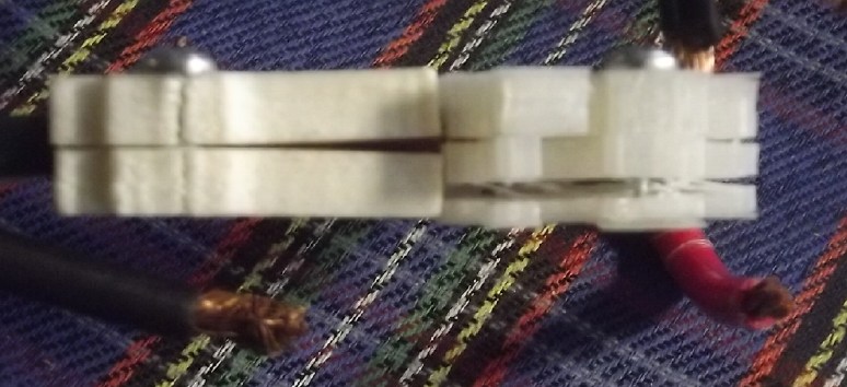
 36 Volt, 50 Amp "Mega T-Socket"
to mount in a
wall plate, with solder-on blades
36 Volt, 50 Amp "Mega T-Socket"
to mount in a
wall plate, with solder-on blades
and "(" springs to push the inserted plug and socket blades together.
Also designs for crimp-on blades, with small flattened copper pipes.
The final socket was printed in nylon for better fire safety than PLA.
Of course, the plate to mount the socket in had to be done and
carefully fitted via several renditions, too.
I had a lot of trouble 3D printing the nylon ("Novamide") filament.
The sockets would split between layers from the pressure when a plug
was plugged in.
It may have been because my "fab" new printer wouldn't heat the print
bed
to the required 110°C temperature, stopping for no evident reason at
100°.
(The other printer will heat the bed to 110°, but once hot
it can't seem to keep it heated up above about 95°.)
 The finished triple receptacle
under sink
allows plugging in a heavy AC inverter
The finished triple receptacle
under sink
allows plugging in a heavy AC inverter
to run a fridge/freezer - and a 36V kitchen lamp - in case of power
failures.
Next was a plug for the crimped connections with flattened pipe.
I 3D printed one and the pipes fit in, but I haven't used it yet.
 .
.
After that, a two-piece case to mount 20 amp DC to DC power adapters in.
These will convert the 36V DC from the wall to any desired lower
voltage,
as set by a 10 turn potentiometer. (Another pot can limit the current.)
I added the ears so they could be mounted on a wall instead
of just left lying on the floor like many AC power adapters.
(This is where I left off last fall when a piece broke on the printer.)
 I hung the power adapter for my
laptop (12V DC)
I hung the power adapter for my
laptop (12V DC)
by one ear behind and below my computer table in the cabin.
Faraday Cabin Construction
The cold weather
that kept me from winding motor coils also kept me out of the cabin.
But before the end of the month I did get
the southwest-quarter floor joists cut and in, and some styrene foam
insulation in. The insulation on the west wall was styrene foam sliced
up with hot wire cutters (see TE News #200) including a float off the
beach and medicine shipping coolers. Since the cooler pieces were only
2 inches thick, I bought some long box nails and started pinning up
extra 1 inch pieces in front to fill in the wall spaces better before
putting up the wallboard.


Gardening
I finally realized that I've been growing five tomato plants under LED
lights and
in a window all winter and there's hardly been a flower, much less a
tomato. Before I've had cherry tomatos all winter, using a brush to
pollinate the flowers. At the start of March I bought some "Sungold"
cherry tomato seeds. If I remember right, these were the ones that made
fruit all winter. Apparently "Sungella" (and whatever else I had) was a
poor choice. Big tomatos don't seem to grow flowers in winter either.
 One day I looked at a coffee plant in the window in the sunshine and
realized the fruit was mostly red, ready to pick. There must be a pot
of coffee worth! The other two trees were taller but had fewer and
less ripe fruit.
One day I looked at a coffee plant in the window in the sunshine and
realized the fruit was mostly red, ready to pick. There must be a pot
of coffee worth! The other two trees were taller but had fewer and
less ripe fruit.
Coffee berries are edible but are hardly more than a
thick
skin over the two seeds - something akin to rosehip skins/fruits.
Probably
lots of vitamin C?
 Before the end
of the month I set up my fab insulated beehive again. For three(?)
years I've put it out in March but no Haida Gwaii acclimatized honey
bees have decide to adopt it. They're not common, but when there is a
hive somewhere and they find the broom flowers, there are a lot of bees
around. There seems to be more than one species.
Before the end
of the month I set up my fab insulated beehive again. For three(?)
years I've put it out in March but no Haida Gwaii acclimatized honey
bees have decide to adopt it. They're not common, but when there is a
hive somewhere and they find the broom flowers, there are a lot of bees
around. There seems to be more than one species.
No one has had any luck trying to import "the usual" bee
species into this cool, damp coastal climate. Most of them like warm
and sunny summers, and they die off here.
This time I set it out on top of a stump around the north
side of the house. It's clear flying in all directions from here. Maybe
a better bet?
Hope, hope! (The stump is sloped. The hive is leveled with the stand
screwed to the stump.)
Approveable Grid-Tied Solar System Kit Arrives
On the afternoon of the 28th my 7 KW grid-tied
"legitimate" solar kit
arrived. It has come with all the right parts and pieces to get
approved for
connection to the power grid. Twenty 350 watt solar panels, 10 dual
grid tie inverters with power monitor, and everything to mount them and
hook them up. Except for the BC Hydro 75%
rebate for grid-tied solar where the grid is generated by diesel (as on
Haida Gwaii), I'm not sure why I
ordered this at this time. I haven't found a contractor. I'll probably
have to install it all myself,
and I really have plenty of time consuming projects! And it's time to
start garden seedlings!
Now I have a garage full of solar panels and equipment,
the Sprint car out in the rain along with the long rails to mount the
panels on the roof, and I've I spent 15,500$ to start yet another
project. (7000W Solar kit 11,000$; shipping from Ontario 4500$)
 The main package: 20 solar panels
and all the
parts and components.
The main package: 20 solar panels
and all the
parts and components.
 The solar panel mounting rails
that bolt to the
house roof.
The solar panel mounting rails
that bolt to the
house roof.
 The delivery truck made my
spacious driveway look cramped.
The delivery truck made my
spacious driveway look cramped.
In
Passing
(Miscellaneous topics, editorial comments & opinionated rants)
Planetary
Management
-
Unrepresented
Constituencies
All the land is divided into "constituencies" for
political purposes, and everyone gets to vote. Seems democratic! How
can there be "unrepresented constituencies?" But what is a
constituency? It's a grouping of people who are entitled to vote for a
legislative representative. Area of residence is just one way to group
people together. It's not the only way, and it's not the most
meaningful.
What is the purpose of a legislature? It was conceived to
be a representative cross section of the society that elects it,
reflecting many different viewpoints and fields of knowledge. Instead
we have what usually becomes an overly large body of people, each one
similarly representing "an area". "Areas" are the only thing
represented. No other, more meaningful grouping of people has any
representation in the legislatures. And because politicians all
represent "areas", they are in many ways a homogenous type of person, a
"political class" who divide into a small number of "parties" whose
members all vote alike on every subject - hardly a cross section!
Rarely does one of these legislators have expertise in any special area
except maybe law, and so they rely on the advice of unelected bodies
when making most of their decisions. One former town counselor recently
told me their council didn't make decisions - they just rubber stamped
what unelected committees of "experts" told them should be done. Too
often those we elect to lead us are being told what to do by the
unelected, and especially by the civil service they are supposed to
oversee, because simply being elected doesn't somehow make one
qualified to make good decisions on many and various matters.
Why do corporate interests lobby government? Because
industries don't have any representatives in the legislatures, but as
organized, money making groups, they have the money, resources and will
to seek to be represented one way or another, even by buying "unfair"
or "undue" influence. But what about all those groupings of people who
aren't organized in such a way that they can hire lobbyists? They are
"unrepresented constituencies".
We should drop the "by area" representation and instead
elect legislative
members as members of other types of constituencies. Here is an "off
the cuff" list of potential constituencies which might be entitled to
elect one or more representatives to legislatures:
* Industry, and perhaps by type of industry: resource industries,
manufacturing, service industries...
* Small businesses
* Labor: construction, electrical, various trades...
* Skilled labor: electronics, computing...
* Creative Artisans: musicians, artists, inventors...
* Farmers and Ranchers
* Transport workers
* Financial services
* Distinct Racial or Cultural Groups
* Homemakers
* Educators: primary and secondary
* Academics - universities, colleges and technical institutes
* Health Care: doctors, nurses, care workers
* Sports associations
* Philosophical and religious groups (Does "separation of church and
state" really mean "religious bodies are not permitted legislative
representation?" Is that the way it should be?)
(Note: This list is surely not "right" or "complete" --
and anyway should be ever subject to review as times and society change)
How would one know what constituency(s) they are members
of? Simple: People would choose and register their choice(s). One might
be permitted to select one, two or even more constituencies to be
members of - perhaps one would select an 'economic' and a 'social'
constituency. A power company lineman might choose to be a member of
Electrical Workers and a Philisophical group he associates with, and be
able to vote for two legislators. Once registered there would be some
time period before such registrations may be changed, perhaps for
example the ubiquitous seven years.
Those elected will be much more closely related to those
electing, known to them. They work in the same field or have similar
affiliations. They are much more individually responsible to their
electorate. The candidates are known to the voters. They aren't just
faces on TV being being presented with favorable or unfavorable bias.
Ideally many legislatures would be much smaller. It is
hard for hundreds of people to hold a discussion and reach a
conclusion. Many of the legislators will have their own expertise in
their field, and may lead the discussion when issues in that field are
under consideration, instead of preselected party leaders dominating
the agenda and decision making. And if a group with selfish motives is
recommending things to the legislature that aren't really in the common
interest, that can be argued against because one or more of the elected
knows better, instead of simply acquiescing because, "Well, they're the
experts".
At the present time it seems to me that much legislation
is passed with little thought or consideration of its various
consequences, by a body of legislators not qualified by knowledge or
experience to enact it, which then becomes a restriction or burden to
reasonable freedom of action by everyone, and perhaps to unintended
groups. And all legislation is vigorously enforced by zealous civil
servants, and is rarely rescinded.
If a good range of constituencies is represented, the
constituencies affected by specific issues will have the understanding
and the power to bring them to the table not only for better
legislative enactments, but also for modification or cancellation of
previous legislation as society changes and evolves, or if problems are
found therein.
Scattered
Thots
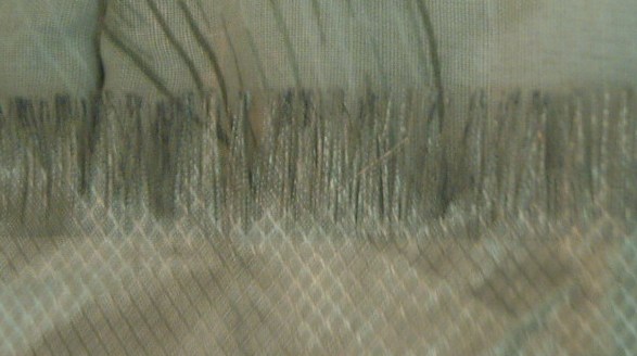
 * I bought two
meters of conductive fabric to connect to ground and lay on top of my
quilt in
bed. (to reduce the AC EMF voltage being induced into my body and
causing tinnitus.) Items I've bought made from "conductive fabric"
before have been megohms. One fitted sheet was "only" tens of kilohms.
Even the cords to plug them into AC plug ground pins were 100 ohms. How
do you even make a piece of wire with such high resistance? But this
piece of cloth from "High-End EMF Shielding Factory Store" on
AliExpress was ZERO ohms - a perfect conductor!
* I bought two
meters of conductive fabric to connect to ground and lay on top of my
quilt in
bed. (to reduce the AC EMF voltage being induced into my body and
causing tinnitus.) Items I've bought made from "conductive fabric"
before have been megohms. One fitted sheet was "only" tens of kilohms.
Even the cords to plug them into AC plug ground pins were 100 ohms. How
do you even make a piece of wire with such high resistance? But this
piece of cloth from "High-End EMF Shielding Factory Store" on
AliExpress was ZERO ohms - a perfect conductor!
My one complaint is that the end is fraying rapidly, one
strand after another until 3/4 of an inch is gone in a few weeks.
Obviously it should be properly sewn up or have some polyamide melted
into it at the ends to hold the threads together before use.
ESD
(Eccentric Silliness Department)
* Is the glass half full or half empty? -- It depends if you're filling
it or drinking it.
"in depth reports"
for each project are below. I hope they may be useful to anyone who
wants to get into a similar project, to glean ideas for how something
might be done, as well as things that might have been tried, or just
thought of and not tried... and even of how not to do something - why
it didn't work or proved impractical. Sometimes they set out inventive
thoughts almost as they occur - and are the actual organization and
elaboration in writing of those thoughts. They are thus partly a diary
and are not extensively proof-read for literary perfection,
consistency, completeness and elimination of duplications before
publication. I hope they may add to the body of wisdom for other
researchers and developers to help them find more productive paths and
avoid potential pitfalls and dead ends.
Electric
Transport
Unipolar
"Electric
Hubcap"
Motor...
Plastic
Recycling?
Waiting for the magnets for the rotor, for warmer weather
to wind coils out in the shop, and trying to order plastic that a
store's lying computer said couldn't be shipped here, I didn't do much
on the motor.
The story on the plastic: I had been ordering a sheet of
1/2 inch polypropylene-copolymer for the motor housing but the seller
had made a mistake, somehow adding an extra piece. Finally on the 9th
everything was cleared up and ready and I hit "checkout"... and then
the computerized checkout page said "can't ship to your address." The
shipping cost had already been looked up and was on the quote. I
emailed the seller and said shipping by post office ground is no
different to here than to anywhere else - it's air mail we don't have.
But he said he couldn't override the system! So I simply can't buy it,
for no actual reason. Now what? As everything gets more and more
automated, this is happening more and more often when I try to buy
something and it's is getting to be more than annoying. I have already
complained to Canada Post. A reply claimed they had finished with my
request, but they did nothing about it. I may be making the motor
housing out of plywood after all!
The magnets finally came from AliExpress.
[29th] Being unable to order the PP copolymer, I could make the motor
body out of plywood... or... I could cast my own PP from old beach
ropes. Either way the special shapes would be routed on the CNC table.
The dimensional stability of inert plastic would be good to have. I
have plenty of it and it's free. (Hmm... if I'm to use a router
on it, what I select and clean had better be pretty free of bits of
beach sand!)
But I haven't been especially pleased with the quality of
my PP tiles. They're good enough for garden edges or pavers or even
VAWT blades... but a motor body? They have voids and missing corners,
bits of sand and spots that just aren't well stuck together. The
problem is that the plastic wants to form into a fat blob in the middle
and it takes tens of pounds of weight on top of the mold to squeeze it
out to the edges.
On March 1st I thought of a lever system. If a lever
presses on the top of the mold with (eg) 5 to 1 leverage, a five pound
weight will exert 25 pounds of pressure. Just a couple of those is
already more than the 40 pounds I've typicly been using. If one also
makes the device go underneath the box mold to support the mold right
under where it presses, it will be able to take more pressure without
bending. Two ten pound weights would give it 100 pounds of pressing
force. (That might even do UHMW?) And an oven rack, if used, would have
1/5th of the weight trying to bend it. I can visualize it. It could be
made from square/rectangular steel tubing to accommodate a range of
mold sizes.
And so somehow making the new motor brings me back
to plastic recycling.
I found an interesting video where Chat GPT AI configured an
axial flux motor virtually identical to my Electric Caik type motor.
AI designed this Axial flux motor - Dean Zylman
https://www.youtube.com/watch?v=kBfxxZb-OGo
Other
"Green"
&
Electric
Equipment
Projects
"Faraday
Cabin"
Construction (long continued)
 Having got some of the floor joists in in the southwest quarter in
January, the weather got really cold: -5°. Then I had to find some
boards about the right length to use for the shorter joists, which I
dug out of a "miscellaneous" lumber pile I opened up on a day it wasn't
raining.
Having got some of the floor joists in in the southwest quarter in
January, the weather got really cold: -5°. Then I had to find some
boards about the right length to use for the shorter joists, which I
dug out of a "miscellaneous" lumber pile I opened up on a day it wasn't
raining.
At almost the end of the month it was warmer and I put in
a couple more, and then finished them on the 27th. I didn't fasten
down the plywood, as I had some blocking and tidy-up to do underneath
first.
 Someone gave me seven styrofoam
coolers. I cut
up three one day and have
Someone gave me seven styrofoam
coolers. I cut
up three one day and have
used some of the pieces for cabin insulation.
 Someone told me there was a piece
of styrene
foam on a beach.
Someone told me there was a piece
of styrene
foam on a beach.
All I found were some little balls. They weren't worth the effort
except that it got them away from the water.
(The real piece is visible from the highway in the
distance, and big, but not easy to get to or haul away.)
I didn't remove previously done
fiberglass. I
just added styrene foam pieces where
there was none, so the west wall is insulated except the upper 'gable
end' above the beam.
I got some long nails to pin more insulation 'sheets' in front
in thinner sections before I put the wall paneling on.
"Bedroom Sand Battery" Experiment
My battery systems each
hold around 10 KWH and I hesitate to drain them even half way overnight
for several reasons. With no connection of the solar to the power grid,
a way to store solar energy besides in batteries would be valuable. And
what needs more energy than home heating in cold weather? In my case
especially, the bedroom needs heating at night, so something that would
store at least a day's solar energy for release overnight would be
great. How big should a "sand battery" be to have some practical value?
5 KWH might be a figure to think about. 10 would be better. In these
experiments I started to see how much sand that might require. It won't
be a portable amount!
[6th] I put
some sand in a metal pail. I had a wire heat assembly from
a 1500 watt electric radiant heater. I wired that and put it in, then
added
more sand until there was 30 pounds - about half the bucket.
I could have used some loose resistance wire and wound it
around in the sand. The advantage of the pre-made heater coil was that
it was a known 150 watts at 38 volts in two parallel sections of under
2 amps each, so it would heat the sand without the wires getting too
hot. I stuck in a tall lab thermometer. To keep the top below the top
of the pail, the bulb was fairly near the bottom. The heater was also
fairly near the bottom. I put it midway between where I thought the
heater ended and the side of the pail.
I ran a first test with two hours of heat, stopping when
the reading hit 80°. The pail was quite hot and the sand next to the
heater was probably close to 100° at that point, and I didn't want to
melt the cooler. Then I measured the energy retention for some hours,
and got the readings in the table below.
AFAIK the energy content should be proportional to the
square of the temperature difference. If the room was 23° and the pail
hit 80°, that's 57° difference which took 307 watt-hours of energy to
attain. The pail was very hot, and remained very hot for some time with
the cooler lid closed, but compare 307 watt-hours to a 1500 watt heater
running for an hour: 1500 watt-hours. The pail of hot sand isn't going
to keep a bedroom warm very long once the lid is opened to release its
heat. Worse, as seen below if the solar ends at (eg) 3 PM and bedtime
is at 11 PM, in those eight hours most of the heat energy will already
be lost even through the insulated cooler.
Since the sand wasn't evenly heated, the calculations may
be somewhat off. The heat was turned off at 14:05 and evidently it took
until 15:00 for the heat concentrated around the heater area to spread
more evenly through the sand. After that temperature started to drop
via leakage to the outside. From 15:00 to 16:00 the temperature dropped
by 7° leaving a difference of 50°. We get: 50^2 / 57^2 = 83% of the
heat still retained, or 17% lost, after one hour. From 307 WH that's
307 * .83 = 236 WH of retained heat. And so on over the hours.
By bedtime there was only about 20% left - 60 WH - and
most of the
remaining heat would be lost fairly soon once the cooler was opened to
radiate heat into the bedroom.
Time
|
Temperature
°C
|
Watts
|
Watt-hours
(Reading - Cumulative),
Energy Retained (WH - %)
|
Notes
30 pounds of packed sand in pail,
in styrene foam box cooler, lid on.
|
12:00
|
20
|
148
|
0
|
|
13:15
|
52
|
153
|
|
Outside of pail quite warm toward bottom.
(Oops, I just put pail in cooler now.)
|
13:45
|
72
|
152
|
|
Top of sand quite warm
|
14:05
|
80
|
150
|
307 - 307
|
Top of sand Very warm. Steaming.
Turned off heat.
|
14:40
|
80
|
0
|
|
Still steaming
|
15:00
|
80
|
|
|
|
16:00
|
73
|
|
256 WH - 83%
|
Still steamy
|
16:30
|
70
|
|
235 - 77
|
|
18:15
|
61
|
|
178 - 58
|
less steamy
|
19:40
|
53
|
|
135 - 44
|
|
21:40
|
46
|
|
102 - 33
|
No steam
|
23:18
|
43
|
|
88 - 29
|
|
After this I added another 30 pounds of sand to the bucket
making 60.
This time I left the sand loose. Before, I had packed it down.
 [7th] I filled
the bucket full, 60 pounds of sand. I got the following figures from an
afternoon heating:
[7th] I filled
the bucket full, 60 pounds of sand. I got the following figures from an
afternoon heating:
Time
|
Temp
|
Watts
|
Watt-Hours
|
14:14
|
27°
|
148
|
Initial reading: 307 WH
|
14:30
|
|
|
added 30# more
sand, total 60#
|
14:44
|
37°
|
156
|
|
15:15
|
52°
|
156
|
|
15:30
|
60°
|
148
|
|
15:47
|
66°
|
153
|
final reading: 547
|
|
|
|
Total 240 WH. Sand at
the top was still cool.
|
but I started too late in the day and couldn't put much energy into it
before the sun got low. I wasn't going to rob the electric battery to
pay the "sand battery"!
[8th] I tried to run a test, but when it hit 80 it quit working. I
shovelled out sand until I could dig out the heater. It turmed out that
the heat fuse had blown. I bypassed it.
[9th, 10th] I ran two day-long tests, of which the 10th may be
illustrative. The sand started out still a little warm after the 9th.
Time
|
Temp
|
Watts
|
Watt-Hours
(readings)
|
11:11
|
29° |
151
|
1303 STARTED HEATER
|
11:43
|
30° |
|
|
14:07
|
70° |
157
|
1753
|
14:55
|
83° |
150
|
1870
|
15:20
|
88° |
150
|
1938
|
15:43
|
91° |
156
|
1932
|
16:00
|
95° |
148
|
2083 STOPPED
Outside of pail hot
enough to burn hands
Total: 780 watt-hours
|
18:30
|
91° |
|
NOW it's steaming?
Heat near the top of
the pail lags that
closer to the heater
nearer the bottom.
|
20:00
|
88° |
|
|
22:00
|
80° |
|
Still steamy
|
23:40
|
72° |
|
" "
|
00:20
|
71° |
|
|
04:30
|
65° |
|
What am I doing up?
|
9:05
|
45°
|
|
|
11:05
|
45° |
|
All but 24 hours
|
[11th] That was on the tiles by the woodstove. I wanted to try it in my
bedroom. Because the handle had to be folded down to fit the pail into
the cooler I could only grab the top edges of the bucket and I couldn't
lift it out. To I move it I had to shovel some sand out, then pour it
back later. I tried it out but didn't take many readings as it heated.
I turned the sand heater On in the morning. By 16:00 the
sand measured 93° with 804 WH of energy having been put into it. By
then as before solar power was waning and I shut it off. At bed time I
opened the cooler lid and also turned on a 200W heater (run from the
battery at 36 V DC: 1500W + 500W at 1/10th power = 200W). I would
remark here that the pail of sand smelled. I think once the sand is
dried out that should stop, but I didn't run any subsequent tests.
[until March - smell was much reduced] It was -5° outside. The night
time readings were:
Time
|
Room
temperature
|
16:00
|
? (sand 93°, 804 WH) |
00:15
|
18.0° (sand 79°)
(Opened cooler lid)
|
00:20
|
18.4°
|
00:30
|
18.7°
|
00:45
|
18.8° (sand 69°)
|
01:15
|
18.5° (sand 61°)
|
02:05
|
18.2° (sand 50°)
|
02:05
|
Turned on
1750W
baseboard
heater
|
In 30 minutes the sand battery (mostly) plus the small
heater had raised the room temperature slightly. Then it started
dropping. With the sand much cooled I figured it would start dropping
pretty quickly soon and turned on the baseboard heat.
We can judge from the previous table, allowing that the
sand at the top of the pail would be warmer by gradual diffusion than
during heating, that starting with 79° the sand has maybe 600 WH of
heat left from the initial 804 WH. And that by the time it dropped to
~65 in 45 minutes, (by about 1 AM) the sand had released 600-~300 =
around 300 WH of heat into the room, which (along with 150 WH from the
200W DC heater) raised the temperature slightly. That's around 450
watt-hours of heating, to save turning on the baseboard heater for a
couple of hours. But it still will reduce the 'run' time when the
baseboard heater is turned on, saving all the watt-hours it releases.
(Hmm, there seems to be a big discrepancy between table 1 and 2 in how
long and how much energy it took to heat the sand to ~~66° or 70°.
Figures from the 9th are very similar to the 10th. Table 1 started with
with only the original 30 pounds of sand, and the added sand didn't
seem to get warm. I compacted the sand that first time, but kept it
loose after that test - the heat may have transferred into more of the
sand faster when it was loose.)
From the magnitude (or lack thereof) of these figures we
can see that at least hundreds of pounds of sand would be desirable to
absorb more energy, keep the mass warm through the evening and then
maintain a good room temperature overnight when it's cold out. The more
sand there is, the lower the temperature after heating it and so the
lower the losses through the insulation during late afternoon and
evening. A metal garbage can in an insulated box - a larger version of
my test setup with a solid floor for the heavy, hot can - might be a
practical minimum. I expect that would hold 200 or 300 pounds of sand,
which could absorb from perhaps 250 watts all day without getting too
hot. (Provided it was cooled again at night.) 250 watts for eight hours
is 2 KWH, which would be a good dent in baseboard heating energy in
moderate weather, especially if combined with battery powered 150-250
watt heaters during the night.
For practical use, unless it's a huge amount of sand with
the insulation opened just a bit in the night, an automatic thermostat
would be very useful in opening the box more and more as the sand
temperature drops. Another thermostat to turn the heater off when the
sand hits the maximum desired temperature is surely also be a must. As
a 'dump load' it would be heated during sunshine only when there's an
excess of solar power, and that too would require a control.
And finally of course the heat energy has to come from
somewhere: there has to be enough solar collection during the day to
put enough kilowatt-hours of heat into the sand to keep the room warm
overnight. That can happen when the day is sunny and long enough - to
be determined for anywhere but it'll rarely do much around here in
November, December and January. It should be good in September, March,
April and May, and parts of October and February. June, July and August
are usually warm enough heat isn't needed. But it's all as variable as
the weather. Is it practical to have hundreds of pounds of sand in an
insulated box somewhere in a living space? The answer will be
individual. My bets are still on for using the tons of sand under the
floor of
the cabin, with heat energy from a woodstove supplemented by solar via
a warm water piping system, with a warm water radiator to extract the
heat from the sand into the space. Unless the OLAHP makes the whole
thing not worth
the bother.
I could have done another experiment on the sunny 17th,
but didn't think of turning it on in the morning. For the rest of the
month there wasn't any sunshine to spare to heat up sand. The batteries
weren't getting fully charged and I was limiting solar/DC heat in my
bedroom, using mostly the AC power grid baseboard heater.
Open Loop Air Heat Pumping (OLAHP)
It being so cold for weeks I didn't want to go out to the
shop or cabin and work on construction or wind motor coils. Now I
thought how nice it would have been to have this heat pump system
working through all this cold weather. I could work on it in the house,
now, rather than wait and put it in the cabin probably two years from
now when the cabin is done. What was stopping me? I suppose it was
reluctance to drill a 3 inch air duct hole through the wall of my house
for a
temporary experimental installation. I finally decided that was a silly
reason to put it off for yet more years. Holes can be patched.
Air Connections
 I
started out by drilling the 3 inch hole through the house wall. I was
worried about hitting wiring and I stopped as soon as the hole saw got
through the drywall and I could pull it off to look. Instead, I had hit
a
wall stud on one side. Somehow that possibility had never even entered
my mind, or I could have used the stud finder. I had to move it over
more than 1/2 a hole in order that the hole saw's center drill have
something to hold onto.
I
started out by drilling the 3 inch hole through the house wall. I was
worried about hitting wiring and I stopped as soon as the hole saw got
through the drywall and I could pull it off to look. Instead, I had hit
a
wall stud on one side. Somehow that possibility had never even entered
my mind, or I could have used the stud finder. I had to move it over
more than 1/2 a hole in order that the hole saw's center drill have
something to hold onto.
 Then there was nothing to
align the outer siding hole to the inner gyproc one, and I got it off a
bit. But with some filing the PVC pipe went through. It even angled
down a bit to help keep rain out. Later I thought to put an elbow on
the outside, pointing down, to keep out rain and reduce wind effects.
Then there was nothing to
align the outer siding hole to the inner gyproc one, and I got it off a
bit. But with some filing the PVC pipe went through. It even angled
down a bit to help keep rain out. Later I thought to put an elbow on
the outside, pointing down, to keep out rain and reduce wind effects.
[11th] Perry had given me a defunct
indoor heat radiator unit from a heat pump. I got the fan running on it
a year ago and put it up on the wall. (TE News #189) I figured
it could work with air instead of refrigerant, and it seems to do so.
He
also
gave
me
a bunch of copper pipe pieces, and I found a couple that
had the fittings to connect to the radiator unit. I went through my
pipe fittings and came up with the various adapters and elbows to
connect the refrigerator compressor I'm using for now to the radiator,
with a pressure gauge in the line. I only had to cut and solder a
couple of pipes.
The other main component was the indoor-outdoor heat
exchanger to passively warm air coming in from outside through the
above mentioned air hole.
[12th] I finished connecting all the piping. There were a few leaks in
compression
fittings, my joinings of PCV and copper pipes with pipe clamps, and
even
in soldered copper connections. Some were inside the indoor-outdoor air
heat exchanger. In one annoying one I unsoldered and redid a copper
elbow twice and it still leaked exactly the same. I finally replaced
the short copper pipe - I think it had a pinhole somewhere, tho I
couldn't see it. Then it leaked yet again at the other end of the short
piece and I had to pull it out and resolder it yet again. I also tried
to reuse a dual adapter compression fitting to join 1/2" to 3/8" copper
pipe. But the 3/8" fitting had been too compressed and wouldn't go on
nicely or without leaking.
[13th] I was going to drive to town and get another compression
fitting, but then I looked through my fittings and replaced it with a
1/2" pipe union, two pieces of pipe and a 1/2 to 3/8" solder-on
adapter. That took less time than driving to town and back.
 In lieu of the desired rotary compressor-decompressor I used a
fridge compressor in a wooden box that I made in the 2020 experiments.
There is a 36 V DC fan in the box to extract heat from the compressor
and box even before it gets to the wall radiator.
In lieu of the desired rotary compressor-decompressor I used a
fridge compressor in a wooden box that I made in the 2020 experiments.
There is a 36 V DC fan in the box to extract heat from the compressor
and box even before it gets to the wall radiator.
 Originally the fan blew the
air out this hole in the side of the box, where the compressed air pipe
also comes out. (Seen above at bottom of box, to right of fan, but
poorly visible. In 2020 it blew into the "dryer vent pipe" radiator
with finned copper compressed air pipe inside.)
Originally the fan blew the
air out this hole in the side of the box, where the compressed air pipe
also comes out. (Seen above at bottom of box, to right of fan, but
poorly visible. In 2020 it blew into the "dryer vent pipe" radiator
with finned copper compressed air pipe inside.)
 After the
first test I tried opening a crack in the top of the box to blow more
air across the compressor body. The whole compressor and box ran
cooler, as shown by "pipe from compressor" temperatures in the diagram
below.
After the
first test I tried opening a crack in the top of the box to blow more
air across the compressor body. The whole compressor and box ran
cooler, as shown by "pipe from compressor" temperatures in the diagram
below.
When all the
leaks seemed to be cured and the compressor
would fill the lines to 60 PSI, I turned it all on - the compressor,
the radiator blower, and the 36V fan inside the compressor's wooden
box. The five room space consisted of the kitchen and dining areas, two
small alcoves and the medium-large front entry. Really it was much too
large for the expected heat output. Also the refrigerator would come on
periodicly and add heat to the space, messing up the readings.
(I had actually wanted to have the unit out of the kitchen space
because of the fridge, but presently there is nowhere else that would
work. I don't dare turn it off, because I would surely forget it and
the frozen food would thaw.)
Then I started measuring temperatures, all laboriously
with the same slow-acting digital thermometer over two hours (12:15 -
14:15). I used just one (except for the outdoor temperature) because
they are more precise (to .1°) than accurate (± .3 or .4°?) and I
wanted
the relationships between readings to correlate exactly, as close as
possible. This was well considering how close together some of the
temperatures actually were.
It was just above freezing outside (+0 to +2°. I opened
the output nozzle a crack to set the compressor air pressure to 45 PSI.
At that pressure the fridge compressor used about 100-105 watts. That
was the heating power. The 35 or 40 watts of fans were just a bit of
radiant heat: they didn't contribute to the heat pumping per se - only
to the total power consumed.
With no "air engine" decompressor, the decompressing air
hissed through a plastic hose straight outdoors through a smaller hole
in the wall made in 2020. (It's behind the compressor's table.)
Here is a drawing with some temperature
readings from lengthy tests 1. and 2. Somehow the compressed
air flow coming from the compressor was pathetic - much less than I
expected. The temperature [with the box cracked open] was only in the
upper 20's range and the compressed air flow was
so slow that it lost much of what little heat it had just in the
pipe
going to the radiator. - seemingly mostly in the first few inches where
air from the box was blowing past the pipe.
If the air going into the radiator was even, say, 25°, the
room would have got warmer. 30° would probably have provided enough
heat for most weather. At just 4 to 4-1/2° warmer than the room air,
there
wasn't much heat to radiate.

* In the first test the top of the compressor box was closed. Then I
opened the top of the box a crack, making a slit. The air coming out
the slit cooled the outside of the compressor better and in the second
test the air from the compressor had the lower temperature reading.
* There was no duct from the exchanger to the compressor [green].
Instead, the compressor drew room air, which was replaced by air sucked
into the building through the exchanger. This configuration provides
fresh air to the
space, but it would also suck air from open windows or air leaks in the
building.
* Contrary to the figures shown, in test 1. air to the room from the
radiator was
~.4° warmer than the room air, similar to test 2. (The figures shown
were from different times during the test, during which temperatures
had shifted a bit.)
* I neglected to measure the compressed air temperature
coming out of the indoor-outdoor heat exchanger on both tests -
rats! [light blue pipe] The exchanger must have worked fairly well
since the compressed
air went in at about 19 and the warmed outdoor air starting [test 1.]
at 1 or 2°
came out at 15.5° or higher. On the second test there was a strong wind
blowing, which pushed extra air through the unit and lowered the
incoming air temperature - not good for COP.
* Before the second test I found three leaks in the pipes, two of
which were probably there in the first test too. Of course having
compressed air hissing out into the room (or into the heat exchanger)
has a cooling effect rather than warming. We want
it decompressing to the outdoors.
The results seem disappointing. In the first test it
didn't manage to raise the room temperature or even hold it steady,
which a 500 watt portable radiant heater did. On the second test I ran
the electric heater first and it didn't manage to hold the temperature
up either. I could estimate it was probably only providing a COP of 2
or 3. I might generously say 4, so 200 to 300 or maybe 400 watts
of heat
output from the 100 watt compressor.
But of course it's still just a prototype with known problems:
1. The compressor was only running at 100 watts and it's just a fridge
compressor. COP of 10 was not going to be achieved, and even if it was
that's only 1000 watts of heat.
2. The actual compressor is sealed in its outer oil lubricant casing,
so only the casing can be cooled with a fan or other means. The
compressor air inside would be warmer as the pipe can only indirectly
be cooled to
keep the maximum heat-pumped temperature low. Higher maximum
temperature is lower COP.
2. There's no "decompressor" or "air engine" utilizing the spent (cold)
but still compressed air to assist the turning of the compressor.
Instead the spent compressed air is vented outside and wasted. An
assist might add (?)60-80% more power to the compressor so the 100
watts
would have heated like 170 watts. (It seems to me that theoreticly it
should be as effective as the compressor + indoor-outdoor heat
exchanger temperature difference, say 30°C from the compressor versus
(eg) 0°C after all cooling, which is 273°K/303°K=90% energy return, but
there will be mechanical losses.)
3. The "flap" compressor and air engine decompressor should be
substantially more efficient than the piston compressor. I have high
hopes for them. The "flaps" air engine on youtube worked far better
than the same experimenter's immediately previous "sliding vane" air
engines.
[14th] I was surprised and in fact rather dismayed by the low volume of
not very warm air that this fridge compressor put out. It took quite a
while to build up to the 45 PSI target pressure. (It's just some pipes,
not a compressed air storage tank.) Then (once warmed) the
pipe by the output was just 33° at best, and it cooled along the three
foot pipe to 22°. by the time it reached the wall radiator unit meant
the air flow must be pretty pathetic. In fact, the bulk of the
temperature drop was inside the compressor box and in the first few
inches of pipe, cooled by the fan in the compressor box. It hardly
needed the wall radiator! Opening the lid of the box 1/4 inch caused
more air to flow through and cool the compressor's outer shell, further
lowering the temperature in its output pipe to under 30°. That
doubtless helped raise the COP a bit, but the quantity of heat just
wasn't there to start with. (I think the 75 watt "water cooler"
compressor I first tried in 2020 put out more air flow even at higher
pressure - or anyway I got more heat from it - but my memory could be
off or the readings at the time could have been skewed. I'm sorry I
threw it out.)
I can only guess from temperature readings over time
compared to a 500 watt portable heater and to not heating the space at
all, that the 100 watt compressor was only delivering 200-300 watts of
heat via the OLAHP system, COP 2 to 3.
I like to think that the highly efficient rotary "flaps"
compressor-decompressor unit will make all the difference. I found a 3
inch diameter UHMW rod in my stores, and ordered some 1/2 inch thick
UHMW plastic to make the housing from. (With all the UHMW I have, it's
all too thick!) The rod is smooth on the outside, which is necessary
for the rotor. A routed rotor disk would be rough just on the vital
outside edge.
 [19th] I tried
cutting a scrap piece of UHMW with my small hot wire
foam cutter. With 3 amps it was painfully slow. It worked better if I
sawed the wire back and forth, bearing down with a fair bit of
pressure. And
it smoked quite a bit. It was half way through a 7/8 inch thick
piece when the wire broke.
[19th] I tried
cutting a scrap piece of UHMW with my small hot wire
foam cutter. With 3 amps it was painfully slow. It worked better if I
sawed the wire back and forth, bearing down with a fair bit of
pressure. And
it smoked quite a bit. It was half way through a 7/8 inch thick
piece when the wire broke.
I'm not ready to give up on this idea yet - it did melt a
slit into it - but it needs a way to set it up and leave the wire
melting for 10 or 20 minutes, however long it takes, and to make sure
it cuts a straight path. Probably by some jig cutting straight down,
with a
weight on one end of the wire. I can probably reduce the current until
it doesn't smoke, tho it will take even longer.
But for now I used a saw to cut out the rotary
compressor's UHMW body.
Optimal Compressor/Decompressor Designs
A couple of months ago I ran across a video about "air engines"
someone was making. The "Air Engine" or "compressed air motor" was the
same thing I meant calling
it a "decompressor": something that took compressed air and turned it
into rotary motion. His experiments and prototypes were brilliant, and
so was his final
result! All in one short video he tried various sliding vane designs,
then came up with the same idea I've had: to use "pivoting vanes",
which
he called "flaps". Seeing his "Flap Engine" run was exciting,
inspiring. It was far superior to any of the ones with sliding vanes -
and tho he didn't dwell on it, I suspect far superior to any commercial
unit.
Video: I built the BEST AIR ENGINE (New Rotary Design)
https://www.youtube.com/watch?v=udI2dWmwMUE
In the comments some people seemed to think there was
"nothing new" in his designs, but the only comment specificly on the
pivoting vanes (versus the sliding vanes ones) was that as they were
attached to (as a part of) the rotor, they would minimize air leakage.
If the pivoting vanes (or "flaps"; "flappy engine") wasn't a new idea,
I haven't seen it elsewhere except in my own writings. From the sounds
of the video he conceived it himself - Brilliant!
Seeing how well his final motor worked, I think I'll go
back to a similar design for the OLAHP decompressor unit, not anything
like a "Pelton wheel" just blowing the air at a rotor.
Some said three vanes was smoother. One person said "Three
vanes are better than two in all circumstances." But doesn't just one
vane make for the least friction?
For a bit I thought that With three "flaps" one could
probably again make the compressor and the decompressor as one unit, a
la the "ROVACS" unit. Then I remembered that the flaps have to face
opposite directions for "compress" and "decompress". It might be done
with one to three Pairs of flaps?
Look at all the trouble I'm saving myself by not having
had time to work on inferior compressor/decompressor design concepts
before I find better ones!
(Reminder note: I decided to put the OLAHP unit into the
cabin, so the project is on hold until the cabin is at least insulated
and somewhat more finished. That Is getting there, slowly! OLAHP for
COP target of 10 in freezing weather is delayed again, but not
forgotten!)
The rotary compressor takes rotary motion and turns it
into compressed air. The air engine takes compressed air and turns it
into rotary motion. The key difference is simply that the flaps are the
other way around. Having seen it, that's just how I want to do my
'decompressor' unit as well as the already planned compressor. The only
difference is I intend to use alume "flaps", as his flexing plastic for
hinges would doubtless wear out pretty fast. It might be possible to
put two sets of flaps into one rotor, but it will probably perform
better as two separate units on the same shaft, each one optimized for
its own task. Anyway it'll be easier on my brain, and then they can be
fine tuned separately.
I am certain that this "flaps" design is a key to getting
the most out of an air based heat pump unit and attaining that
tantalizing "COP = 10 or better".
[25th] Waiting for a 3D printout I sat down and started designing a
G-code file to rout out the main cylinder bodies for the compressor and
decompressor. I had found a scrap of 1/2" UHMW big enough to cut one
from. Then I got the idea that instead of cutting a 1/2" thick piece
right through and then putting on a top piece and a bottom piece, I
could use the 7/8" size and just rout out a space 1/2" deep. The top
would thus be part of the same piece and it would just need a bottom.
The advantage (besides having lots of material that
thickness) is that there's no join at the top to potentially leak air.
I modified it to rout out a
"basin" cylinder instead of cutting a hole
all the way through.
 [26th] I finished the file
and did a dry run on the CNC table. I caught a couple of problems and
then did the actual piece. It seemed to rout badly, just like the HDPE
last month.
[26th] I finished the file
and did a dry run on the CNC table. I caught a couple of problems and
then did the actual piece. It seemed to rout badly, just like the HDPE
last month.
 It cleaned out
okay with a little scraping, but in spite of using a new router bit the
faces definitely weren't as smooth as previous UHMW routings in
Victoria.
It cleaned out
okay with a little scraping, but in spite of using a new router bit the
faces definitely weren't as smooth as previous UHMW routings in
Victoria.
(It seems to me that previously I was using larger
diameter router bits, eg 3/4 inch, in order to rout out larger volumes.
I now suspect they work better on plastic than the small ones, throwing
the chunks clear with more centrifugal force than small diameters so
they don't melt back in. ...Maybe I could rout HDPE fine with larger
bits? In fact, I think I did one piece of HDPE back in Victoria.)
 I had included
a hole for the piston shaft, off center by 3/8 inch, right through to
the other side.
I had included
a hole for the piston shaft, off center by 3/8 inch, right through to
the other side.
The shaft
bearing had to recess into the other side. I wrote another short G-code
file for that, carefully lined up the machine on the shaft hole, did
the dry run, and routed it out. The bearing only pressed in part way
because I didn't want the plastic to be too thin or even go right
through. It was enough to hold it centered. (The bearing pressed in, a
bit too snugly for my liking. I should have gone for the extra
thousandth of an inch radius if not two or three.)
In case that wasn't enough
for one day, in the evening I did another program for the rotor disk
and routed that too. It came out really fuzzy, and not even quite
round. It was saved by the fact of it being the outside edge. I sanded
it smooth on the bench belt sander. The program had something I had
never tried before: a short arc, for the alume flap. I estimated the
ending position as 33° with a protractor and found the sine and cosine
times the radius to get the end position y and x. Somewhat to my
amazement it worked.
[27th] Instead of alume, I fashioned a flap out of dogwood - more
whittled with a pen knife than cut. Bit by bit
I got it sanded to the right shape. Soon there will be an inlet hole
just to the right of the top, and an outlet hole just to the left, with
a one-way leaf to keep air from coming back into the cylinder from the
system. The leaf opens when the pressure in the cylinder is greater
than that in the system, pushing more air into the pipes.
 1. Top Dead Center: A
cylinder-full of air has been delivered to the outlet tube and the
one-way
leaf has just closed so it doesn't feed back in. The cylinder is full
of
uncompressed air which has been sucked in through the intake port in
the previous cycle. Unit is turning clockwise.
1. Top Dead Center: A
cylinder-full of air has been delivered to the outlet tube and the
one-way
leaf has just closed so it doesn't feed back in. The cylinder is full
of
uncompressed air which has been sucked in through the intake port in
the previous cycle. Unit is turning clockwise.
2. 90° right: Flap presses against outer wall
by centrifugal force and by air pressure. It is starting to push the
air around the cylinder toward the exit hole.
 3. Bottom Dead Center: The air to the left
has now been compressed to 15 PSI (double pressure in half the space).
3. Bottom Dead Center: The air to the left
has now been compressed to 15 PSI (double pressure in half the space).
If the pressure in the piping is less than 15 PSI (at
startup), the leaf will open and allow air to flow.
At the same time, the right hand side is refilling with
(unpressurized) air drawn in through the intake hole.
 4. 90° Left: Here the air is compressed to
higher and higher pressure, potentially over 100 PSI, as it is now in a
quickly shrinking space. As it exceeds the pressure in the system
piping (~40 PSI?) it exits through the one-way leaf.
4. 90° Left: Here the air is compressed to
higher and higher pressure, potentially over 100 PSI, as it is now in a
quickly shrinking space. As it exceeds the pressure in the system
piping (~40 PSI?) it exits through the one-way leaf.
The air engine would be
virtually the same if not entirely identical. It would turn
counterclockwise instead of clockwise. There would be no leaf to stop
compressed air from entering the cylinder. Instead there would be a
nozzle or other device regulating the flow of air coming in on the
left. The compressed air entering would fill the space to the left and
drive the flap/vane around to the right. Air would exit the exit hole
at the top-right through the whole cycle. (By itself it might not start
if the vane was sitting right at top dead center, but in this
application the compressor motor would start everything turning anyway.)
3D
Printing:
New
Printer
*50 Amp "T-Socket", "T-Plug" & Crimp-on Blades
* DC to DC Converter Case
* New Power Monitor
50 AMP T-PLUG WALL PLATE SOCKET
With my repair parts form last summer never having
arrived, and then a new 3D printer (ordered in October) never having
arrived, I haven't been able to do any 3D printing since last summer.
I'm not sure what happened to these. The parts were just a small packet
that somehow vanished from the mail, but I had been hoping the printer
would arrive before the the postal strike. It didn't, and hasn't since.
I didn't claim a refund during the postal strike because I thought it
would come afterward. (Some other things did.) Perhaps it may still
appear some day?
I finally ordered another 3D
printer from Creality Canada, this time a "Creality K1C" enclosed print
model. The print compartment isn't heated, but the print is always at
the top of the chamber, with the print bed going up and down while the
extruder stays at the top. The lid could be put on or left off during
printing. With the lid on, although there's no particular control, the
heated bed itself heats up the whole small printing space for printing
materials such as ABS that want the space warmed. (I haven't tried ABS
yet, but am trying out "Novamide", a nylon like polyamide material.) It
could also print common PLA material very fast, laying out beads at 300
mm per second instead of maybe 60.
This printer arrived pretty quickly in mid February. At
last I could print more wall plates, plug shells and other 36 volts DC
power components!
Printer & G-Code Peculiarities
I was frustrated at first. The printer wouldn't print with
the G-code file generated using the Cura slicer. It heated the extruder
up to the specified temperature, then did an "extruder cleaning cycle"
which left the extruder at 150°C, then said "error 2212" (or some such
number) which, looked up on line, turned out to be "attempt to extrude
cold filament", under 175°. On line a couple of other people had had
the same problem, but no solution was offered.
So I delved into the G-code generated by Cura (G-code is a
plain text file) and moved the temperature setting commands down a few
lines to just above the start of printing, apparently to after it had
finished the nozzle cleaning.
Changing the temperature setting to 150° and leaving it
there when asked to 'initialize' the extruder I would call a mistake in
the printer's firmware.
The change worked... and then it 'error'ed at the end of
the print. The print was actually finished, but the nozzle stayed at
the last print point (making it hard to pull out the printed item), and
the printer claimed the print had failed since it didn't quite reach
the bottom of the file.
So I looked down at the bottom. It told the printer to
turn off the motors, then tried to move the bed to where one could pull
out the part easily, and also do a short reverse extrusion to clear the
nozzle. Of course these things can't be done after turning off the
motors, and the "bed heat off" and "extruder heat off" commands were
likewise a few lines premature. Apparently other printers just ignore
the "motors off" command or turn them on again, where this one flagged
the error.
This one was clearly Cura's mistake. There was a second
"motors off" command a few lines farther down, about where it should
have been. I erased the first one and also moved the "heaters off" and
"fan off" commands down a few lines to after the last printing commands
were finished.
Then it occurred to me that I was using a two year old
version of Cura. I downloaded a new one but it generated the same
mistake(s) in the G-code sequence. (Oh well, even to the last version
of MSDOS, 6.X or something, some floppy disk handling "kludjes" were
never fixed.)
I'm not especially happy about having to manually adjust
each new part printing file in two places, but it works. I suppose I
could probably find some other slicer program, but Cura is supposed to
be the best one.
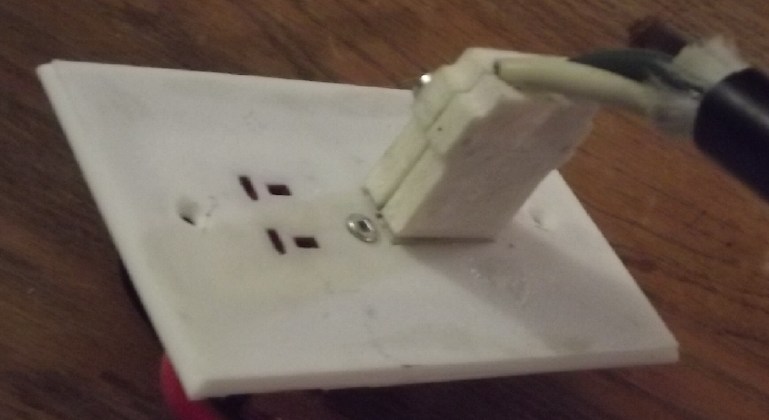
50 AMP T-PLUG WALL PLATE SOCKET &
PLUG FOR CRIMP-ON BLADES
One new piece I've been meaning to get to for years
is a 50 amp socket to mount in a wall plate, the "mega-T-plug" of my
own design. I long ago made the "mega-T-plug" plug for appliances, but
I've been using the porcelain version socket in the kitchen - the only
place I use it. As made, it's just an in-line plug rather than a wall
mounted receptacle. And it doesn't even work very well, the receptacles
for the plug blades twisting around so it won't go in, at the drop of a
hat. I have long figured I could obtain a sufficiently heat-resistant
socket if I made it out of a nylon type of plastic rather than PLA or
ABS, and I got the 'Novamide' filament.
So finally I sat down one day and started designing the
nylon "mega-T-socket" in OpenSCad. Rather than being part of a wall
plate, it would screw into a wall plate that could be made out of
regular PLA, which has more rigidity. For that of course the matching
wall plate had to be designed too.
And I asked myself: in 120/240 volt wiring, high current
stove and dryer sockets are separate from any others. But why? A dryer
plug could for example also have a 230V/15 amp socket in the same plate
for convenience. I actually have a couple of 230V appliances that I
could really use an outlet anywhere for. So it seemed to me that
instead of running a separate line to the kitchen I could have a wall
plate with both the regular and the high current T-sockets. So I
designed one that had two 'regular' small sockets at the top and the 50
amp one at the bottom. Naturally nothing fit quite right on the first
couple of tries.
 I
printed the sockets out in PLA to test for fit, along with the plates,
going through several renditions of each until things fit together
properly.
I
printed the sockets out in PLA to test for fit, along with the plates,
going through several renditions of each until things fit together
properly.
 The first
socket seemed pretty puny considering the heavy wires that would go
into it, so subsequent versions were considerably beefier.
The first
socket seemed pretty puny considering the heavy wires that would go
into it, so subsequent versions were considerably beefier.
The nylon version socket didn't print on the first try. The first layer
printed, but on the second, everything came loose from the bed.
I upped
the temperatures and got it to print with the lid on the printer. When
I went to use it, the screw holes didn't fit the same as with PLA, and
when it was all together with the copper blades and steel springs, when
I plugged the plug in it split apart along a printing layer 'seam'.
I decided to put bolts through to help hold it together,
and had to drill the screw holes bogger. This just made the part break
apart in more places until it was barely usable even to try out.
Okay... how about a hotter print bed temperature next time, which
should also raise the print compartment temperature? I looked up
Novamide. Around 110° was recommended for the bed, but the printer
wouldn't set to more than 100°! I'm sure this is now a big part of my
problem printing nylon ("Novamide").
[23rd] I printed one more nylon socket with slight mods, including
bolts and nuts to hold it on the plate instead of screws that just
delaminated the layers and didn't hold when plugging in a plug.
Then I tried to go back to PLA printer filament. It was a
disaster. I might have done something wrong, but the nozzle ended up
totally clogged, and nothing would dislodge the plastic melted into it,
including with a hot air gun on a bench. A video showed how to take
apart the extruder and I did that first. It was the wrong extruder.
There
was nothing on line about such a problem with this nozzle. This one had
a tube on the back and looked like no
other nozzle. I thought the tube was supposed to separate from the
nozzle and spent time trying to do so, but it isn't.
Somehow the whole day passed by and I didn't get anything
else done nor the printer working again. I ordered a "kit" of four new
nozzles from Creality Canada, which came to almost 100$.
Repair parts had finally come for the old printer and in
the evening I decided to try to fix and use it. Not for nylon; just
PLA. It may not be the
latest and greatest, but the filament is easy to pull out and put in,
and it was easily fixed with the right part.
Then I went to print the item I had originally tried to
print last August for the Renewable Energy Symposium: a case for the
little bare-board 20 amp DC to DC converters. I hadn't counted on the
printing time. The new printer can print the "ultra PLA" filament that
came with it
at 300 mm/minute. The old one is stuck at 60 mm/minute and the little
case took well over two hours. I tried to print with the same old
filament that caused it trouble last August. It printed 3/4 of the case
and finally I noticed that the print head was 1/4 inch above the print:
the filament had jammed and it was just going through the motions
without extruding plastic.
It didn't really matter because enough printed that I
discovered the critical dimensions for the board mounting screws were
off, by 2mm one way and 3mm the other. Way off. I made a few changes to
the design but by now it was very late at night. The whole day gone and
nothing done on anything else!
[24th] I tried
again to print the box, having adjusted the dimensions.
I conceived that perhaps the somewhat kinky spool of PLA jammed when a
kink was drawn into the mechanism, And the mechanism had to yank at the
fairly heavy spool to get it to unwind some more filament. So I turned
the spool by hand to unwind lots of slack filament, and I printed the
top as one print and the bottom separately. It seemed to work and I got
the box printed.
I got an assortment of tiny screws from China. Whatever
one thinks of ordering everything from abroad, in my whole life before
the internet I had never been able to buy small screws. One could only
get them by disassembling electronic equipment, and of course, you
would never find the size needed. To mount the circuit board on the box
base, and to attach the cover to the base: 2mm x 6mm screws.

Pressing my luck I tried to print another with a bit more
"fine tuning", both halves at once, but again the filament stopped
feeding part way through. (If I had printed only the base I'd have got
it. Only the top piece?... maybe. Instead neither one was finished.
Should I abandon several spools of old PLA filament and buy new? What
about my spools of ABS filament and other special types? I didn't know
when I bought it and "stocked up" on it that it had a shelf life!
Perhaps the new printer will like it better?)
[25th] A glutton for punishment I tried again, this time one piece at a
time. And this time I sat there while it printed, and I noticed some
filament dust on the flat space just under the extruder gear. When I
went to clean it off there was also a bent piece about 1/4 inch long.
If that got drawn up into the gear it could well jam it, even multiple
times. Maybe it
wasn't the little kinks in the filament at all? Instead, just that I
hadn't noticed it needed cleaning. Both prints came out fine, and the
printer had no further problems with the old filament.
Well, that was 2-1/2 days with not much else done
instead of just one morning, and 100$ for the new nozzles. At least the
AnyCubic printer is working again, and hopefully the new one (when the
new nozzles arrive) should be good with ABS as well as PLA. (I hope I
don't need to print any more nylon things for a while!)
I
made these DC to DC power adapters with "ears" in case one wanted to
mount it instead of just having it dangling or lying on the floor. I
used just one ear to hang the one for my laptop on the wall under the
table.
Back to the plugs and
sockets... I had had this idea to flatten small copper pipes to make
the 50 amp plug and socket blades for in-line sockets or plugs. Perhaps
they could come out to just the right width and thickness? 12 mm at the
end could be left un-squished and a fat wire (eg, #8 AWG) inserted into
it, then crimped in with a crimping tool. That would be much the
easiest way to make blades, and heavy wires could be crimped in instead
of having to solder them. I used what is called "1/8th inch copper
pipe", which is 1/4 inch outside diameter. The blades ended up with a
dip in he middle, and a bit fat or a bit wide. If I pounded into the
dip, the other face would be pretty flat, and only one face connects
between plug and socket blades. Pipe about 5.5 or 6 mm outer diameter
should be just right. I pounded them down to about the 2 mm thickness
spec and filed the edges a bit so they would fit in the plug &
socket slots. They're still a bit over 8 mm. I plugged individual pins
into the new socket. They seemed to work and hold well.
The catch was of course that plug & socket
shells for such pins had to be designed and printed. I opened the
OpenSCad file for the original plug with the soldered pins to use as a
template. By making just one simple change it seemed just right for the
pipe blades. I noted that that one was designed six years ago to the
day, February 25th, 2019. In fact, it was before I found T-plugs &
sockets, but for a large, high-current version "T-plug" my design is
still just right. (How slowly my projects develop!)
Solder-on
blades, and crimp-on blades made from
small copper pipes. The pipes end up with a dip in one side when
flattened - but only one face of each connects together, along their
whole length.
The loose "("
springs in the socket press the plug and the socket blades together
when the plug is inserted.
I haven't downloaded any of these 3D printer designs
to Thingiverse.com yet, but when I do it's going to be a pretty
comprehensive set of 36 volt DC T-Plug components: various shells for
plugs and in-line sockets, including simple "click-lock" pairs) various
wall plates that fit on electrical boxes with three or four outlets
(all including the high current plugs and sockets), cases for DC to DC
converters and power monitors... more?
[27th] Again
(yes I seem to be repeating myself), a stove
or dryer outlet lets you plug in just the one item. If you have another
230 V appliance, you need to install another outlet for the 15 amp
style plug. The in-line 50 amp T-socket was similar for the 36 volts
DC. I could plug in the big inverter to run the fridge or whatever, but
nothing else. Having finished everything, I 3D printed a slightly
adjusted version of the wall plate, with two regular 20 amp T-sockets
and one big 50 amp. [28th] I installed the finished plate under the
kitchen sink, having already mounted an electrical box. Now when
there's a power failure I can plug in the inverter to run freezers or
the coffee maker, and a lamp so I don't have to use a
little battery light or flashlight to see in the kitchen.
Appliance Plug Fuses
Someone on youtube was complaining that North American
appliance plugs don't have a fuse for fire safety, which he says they
do in Europe. Technicly he's right. Especially with a heavy cable from
a heavy circuit breaker to a skinny lamp cord there's no protection if
the lamp cord shorts. Even a 'regular' 20 amp
breaker might not blow. A shorted #18 AWG cord would probably burn
right out. One could make T-Plug shells incorporating an ATC/ATO
'automotive fuse'. They'd be bulky. I'm not into it myself. (I wonder
how many annual house fires there actually are from this cause?
Probably more than zero.)
(Looks like a face!)
Electricity Storage
Copper Oxyhydroxide
or Nickel Oxyhydroxide
or Nickel-Manganese Oxides
& Zincate Cells
(No Report - maybe next winter I'll get back to it.)
My
Solar
Power
System(s)
(solar panels images - TE
News
#200)
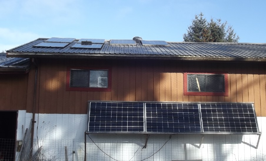
February 12th arond noon. Aside
from the low sun and cloudy, short days
themselves, trees at a considerable distance cast their shadows on the
solar panels.
Most of the tree shadows to the south don't reach the panels in the 5,
6 or 7 months when the sun is higher,
but the row of tall trees on the west side cuts production earlier in
the afternoon than desirable, year round.
New Power Monitor for House Solar Charging
Along with everything else, I went into town and checked
the mail. Four packages had come including the conductive cloth to lay
over the quilt on my bed and reduce the EMF voltage being induced into
my body at night, magnets for the new motor... and a 100 amp DC power
monitor. Other than handling far more current, the big advantage is
that this one doesn't go from '9999 WH' to '10 KWH', suddenly losing
three digits of precision. Instead it has 8 digits, '12345.678' format.
That's to the nearest watt-hour and it won't overflow for years.
The power monitor for the house solar charging was a 20
amp internal shunt unit. Charging the batteries hadn't overloaded it,
but when I tried turning on heaters during charging on sunny days
it would easily pass 20 amps, and I had to be careful not to run too
much for fear of burning it out. So power that could have been used was
going to waste.
I had thought the new power monitor would have come with
the shunt it needed, but it didn't. Chagrined, I checked the order
page. My mistake. It pretty clearly spelled out that one needed to buy
the shunt separately - in fact two 50A/75mV (.0015 ohms) shunts for the
100 amp unit.
But I had bought some volts-amps meters quite a while back
for EV use, and never used them. Since they didn't measure watt-hours,
they weren't much use as power monitors, but there were three 50A/75mV
shunts.
I took two, drilled out the thread on a couple of holes,
and piggybacked one on the other in parallel to get 100 amps. After
dark I took everything out to the garage and mounted and wired the
shunt on the solar wall. Then I tied in the power monitor. It was a
different size than my others and I didn't have a case for it. I had to
leave it just hanging on the wall. (Later I made a "shelf" for it with
two long screws.)
When I reconnected the battery it said 1.2 watts of power
was being used. The meter itself was the only thing connected. I turned
on the breaker and it went to 2.7 watts, so 1.5 to the solar charge
controller. I hadn't expected it to give any reading because it was
connected to read power From the charge controller, not To
it, from the battery. Shouldn't it be -2.7 watts, if anything? It
seemed to treat charge and discharge the same so it all looks like
charging. That will skew the readings by around 65 watt-hours per day.
That's almost trivial except in midwinter clouds when all readings are
pretty trivial.
(Yes, I could stand to at least clamp some of these wires down.)
For some reason the second meter came in a separate
package a few days later. It'll be installed in the cabin system. I
need to make cases for them and properly mount them on the wall. Also I
need another shunt. (Until I get one I can just divide the power and
current readings by two.)
The Usual
Daily/Monthly/Yearly Log
of Solar Power Generated [and grid power consumed]
Notes:
* All times are in PST: clock ~48 minutes ahead of local sun
time, never PDT which is an hour and 48 minutes ahead.
* Unapproved AC/Grid Tied systems have been removed.
* DC meters
accumulate until [before] it loses precision (9.999 WH => 0010
KWH), then are reset - hopefully before that. (Suddenly losing THREE
decimal places of precision is Not helpful!)
* House panels include four old ones on the roof (upper - total rating
~
1000W), two 305W on the roof, three 305W on the south wall below the
roof, and one broken panel mounted verticly on the porch railing (seems
to still work but a lot of shade there).
* Cabin meter is reading LOAD KWH, not SOLAR KWH. These are eventually
the same thing, since the solar charges the batteries for the load, but
not directly indicative of a sunny or cloudy day. (I may put a meter on
the charging some day!)
* Cabin DC includes the three carport panels and the two on a pole in
the yard as well as the four on the cabin roof itself. All nine are
305W.
* The wall, pole and porch panels are easily wiped off from the ground
if it snows.
* Km = Nissan Leaf electric car drove distance, then car was charged.
Car KWH does not add to or subtract from any other readings.
Fotos of solar panels last month: TE News #200
House System Panels: House roof, wall (9 solar panels) - Porch
(1 broken one - usually shady)
Cabin System Panels: Carport (3 - sunniest place on the
whole property) - Pole (2 - shadiest place) -Faraday Cabin (4 - badly
shaded in winter)
New Order of Daily Solar Readings (Beginning November 2024):
Date HouseDC, CabinDC => Total KWH Solar [Notable
power Uses (EV); Grid power meter@time] Sky/weather, notes...
January 2025
31st 4.62, 3.82 => 4.32 [22796@18:30] More sunny! (& snow!)
February
01st ?.??, 4.44 => .62 [?????] Snow. Cloud. Cold! Solar
panels snowed over. In the PM sometime I swept off the five I could
reach.
02d 4.95, 4.44 => .33 [22939@19:00] -7°C all day.
A bit more snow. (.33 KWH generated at house is over Two days!) I got
out a
ladder and swept off a couple on panels on the house roof. Then I
'rebalanced' the four on the ground (that I could sweep snow off of
without a ladder) so two were on the lower section (0-35V) and two on
the upper (35-70V) instead of three:one. The voltages were better
balanced (31:33V instead of 35:26V), but collection only went up from
45W to 55W. Just about no sunlight through the clouds! Why did I
bother? I was sorry I ran 200W of electric heat on the night of the
21st, because with so little recharge there's been barely power for
lights. But it's not Too low unless the dark clouds continue a few more
days. (I prefer the 36VDC lights because they don't have AC electric
fields to worsen my tinnitus.)
03rd 5.75, 4.44 => .80 [23026@18:00] -7° again, still
overcast, windy.
04th 7.77, 5.24 => 2.82 [55Km; 23122@18:30] Still "-"°, but sunny.
05th 2.75, 6.75 => 4.26 [23203@19:00] Still sunny, still fr°zen.
06th 3.95, 7.29 => 1.74 [23278@18:30] Cloudy, but arctic air from
north USA has quit - wind from SE: ~0°.
07th 6.94, 10.2 => 5.90 [23353@18:30] Sun! I ran heaters all day.
('10.2' is a guess. It just said '10', no decimals. I guess I'll have
to reset meters after they hit just '6.000' now, to avoid losing 3
digits precision after '9.999'.)
08th 1.93, 1.87 => 3.80 [105Km; 23422@20:30] part sun
09th 3.49, 3.56 => 3.25 [23484@18:30] cloudy
10th 7.10, 5.82 => 5.87 [10Km; 23547@18:30] Sun! Solar power is
going to waste! (still freezing cold)
11th 3.83, 8.07 => 6.08 [55Km; 23629@19:30] Sun again, -5°
12th 7.98, 2.95 => 7.20 [23706@18:00] sun again!
13th 2.47, 4.03 => 3.55 [23771@18:00] mix clouds, dull sun
14th 3.61, 5.61 => 3.72 [50Km; 23842@17:30] cloudy. -2° w. snow to
+4° w. rain.
15th 3.99, 7.28 => 2.05 [23885@19:30] rain, +4°, storm & wind,
power failed
16th 5.09, 1.55 => 2.65 [23936@18:30] dull as yesterday, +5°, wind
died down, no power fail
17th 8.70, 3.82 => 5.88 [23995@18:30] Sunshine!
18th .36, 4.30 => .84 [55Km; 24053@18:30]
Wind & rain 6°.
19th 2.41, 5.12 => 2.87 [24120@18:30] cloudy but brighter than
yesterday.
20th 4.52, 7.51 => 3.50 [55Km; ?] Rain, Wind - lights flickered
21st 6.76, 1.52 => 3.76 [90Km; 24270@19:00] Cloudy
22d 8.77, 2.83 => 3.32 [55Km; 24363@21:00]Cloudy, drizzle.
23rd 2.11, 3.27 => 2.55 [24411@18:30] mor cloudz
24th 3.78, 4.14 => 2.54 [?] stil mor cloudz
25th 6.05, 5.98 => 4.11 [55Km; 24523@19:00] Started sunny, got more
and more cloudy, by evening strong winds.
26th 7.65, 6.69 => 2.31 [24586@18:30] howling winds abated. rain.
27th 3.82, 8.09 => 5.22 [24661@18:30] some dull sun, then clouds.
(No full recharge for 10 days.)
28th 5.14, 1.67 => 2.99 [85Km; 24733@19:00]
March
1st 7.74, 1.72 => 2.65 [60Km; 24833@'24:00'; 50Km]
2nd 11.24, 4.41 => 6.19 [24881@19:00] Mostly sunny. (New meter
goes past 9999 WH, yay!)
3rd 14.61, 6.30 => 5.16 [60Km; 24949@18:30]
4th 15.90, 7.64 => 2.63 [25009@18:30] Dull again.
5th 20.71, 12.5 => 9.67 [24069@18:30] Really sunny! (12.5...
somewhere between 11 and 13!) The batteries were a bit low and absorbed
some KWH, and I ran heaters all day. (Starting at 5° in the morning,
the cabin bedroom hit 20° before the end of the day with 750W of heat
on.) Often the 'PowMr' charge controllers were doing over a kilowatt.
For the first time I can remember their cooling fans came on. I tried
grafting onto apple and pear tress - 6 grafts in all. I planted the
black walnut. I started 'cold stratifying' some birch and black locust
tree seeds that I bought many moons ago. Someone mentioned that they
might become invasive species. I'm more concerned with putting wire
around every one of them so the deer don't gobble up the saplings. I
doubt they will spread without help. Almost the only softwood on these
islands is red alder - the deer don't seem to like it.
6th 21.93, 1.29 => 2.51 [25127@18:30] Cloudy again
7th 26.76, 4.17 => 7.71 [25186@19:00] & today mostly sun
Chart of daily KWH from solar panels. (Compare February 2025 with January 2025 &
February 2024.)
Days of
__ KWH
|
February
2025 (18
Collectors, DC/
Batteries only)
|
January 2025
(18 C's)
|
February 2024
(18 C's)
|
0.xx
|
4
|
9
|
1
|
1.xx
|
1
|
7
|
2
|
2.xx
|
8
|
10
|
4
|
3.xx
|
7
|
3
|
|
4.xx
|
2
|
1
|
2
|
5.xx
|
4
|
|
2
|
6.xx
|
1
|
1
|
4
|
7.xx
|
1
|
|
3
|
8.xx
|
|
|
2
|
9.xx
|
|
|
2
|
10.xx
|
|
|
2
|
11.xx
|
|
|
3
|
12.xx
|
|
|
1
|
13.xx
|
|
|
|
14.xx
|
|
|
1
|
Total KWH
for month
|
94.43
|
61.32
|
201.53
|
Km Driven
on Electricity
|
682.7 Km
~100 KWH
|
893.2 Km
~120 KWH
|
967.2
(130 KWH?)
|
Things Noted - February 2025
* Another cloudy month - no real sunshine in the last 11 days.
* Nevertheless it is apparent from previous year February figures that
without grid ties harvesting all the available solar energy, much is
being wasted on whatever sunny days there are once the batteries are
charged.
Monthly Summaries: Solar Generated KWH [& Power used
from grid KWH]
As these tables are getting long, I'm not repeating the log of monthly
reports. The reports for the first FIVE full years (March 2019 to
February 2024) may be found in TE
News
#189,
February
2024.
2024
Month: HouseAC + DC +Carport+Cabin[+DC] (from Aug 2024)
Jan KWH: 31.37 + 3.14 + 16.85 + 16.82 = 68.18 [grid
power used:
909; car (very rough estimates): 160*]
Feb KWH: 96.52 + 2.36 + 49.67 + 52.98 = 201.53 [grid: 791; car:
130]
FIVE full Years of solar!
Mar KWH 150.09+ 1.63 + 93.59 + 92.50 = 337.81 [grid:
717; car:
140]
Apr KWH 181.89+35.55 +123.50+142.74 = 483.68
[grid: 575; car: 140]
May KWH 129.23+67.38 +109.6 +126.32 = 432.53
[grid: 405; car: 145]
Jun KWH 152.54+51.02+118.99+141.17 = 463.72
[grid: 420; car: 190]
July KWH 174.22+30.53+111.19+128.62 = 444.56
[grid: 386; car: 165]
Aug KWH 221.99+ 2.63 +142.49+151.67+ 5.78 = 524.56 [grid: 358;
car:
180]
SeptKWH 120.98+ 2.49 + 83.50 + 19.10+ 39.95 = 266.02 [grid: 662
(yowr!); car: 155*]
Oct KWH 78.48+ 7.29 + 64.39 + 7.52 + 40.75 = 198.43
[grid: 711; car: 120*]
Nov KWH 19.63+12.19+ 23.90 + 3.35 + 25.62 =
84.69 [grid: 900 (ACK!);car: 110*]
Now solar is charging
batteries only. 2
DC systems: house, cabin.
Dec KWH 20.37 + 16.76 = 37.13 [grid: 1866 (using electric
heat!); car: 120*]
2025
Jan KWH 35.02 + 26.30 = 61.32 [grid: 2136 (electric heat
OW!); car: 120*]
Feb KWH 55.43 + 39.00 = 94.43 [grid: 1937; car: 100*]
SIX full Years of solar!
* Car consumption comes from solar and or grid: it
does not add to
other figures. (Just from grid from Nov. 18th. 2024 on)
Annual Totals
1. March 2019-Feb. 2020: 2196.15 KWH Solar [used 7927 KWH
from grid; EV use: -] 10, 11, 12 solar panels
2. March 2020-Feb. 2021: 2069.82 KWH Solar [used 11294 KWH from grid;
EV use: - (More electric heat - BR, Trailer & Perry's RV)] 12 solar
panels
3. March 2021-Feb. 2022: 2063.05 KWH Solar [used 10977 KWH from grid;
EV use ~~1485 KWH] 12 solar panels, 14 near end of year.
4a. March 2022-August 2022: in (the best) 6 months, about 2725 KWH
solar - more than in any previous entire year!
4. March2022-Feb. 2023: 3793.37 KWH Solar [used 12038 KWH from grid; EV
use: ~1583 KWH] 14, 15, 18 solar panels
5. March 2023-Feb. 2024: 3891.35 KWH Solar [used 7914 KWH from power
grid; EV use: ~1515 KWH] 18 solar panels
6. March 2024-Feb. 2025: 3428.88 KWH Solar [used 12773 KWH from grid;
EV used: ~1685 KWH]
Money Saved or Earned - @ 12¢ [All BC residential elec. rate] ;
@ 50¢ [2018 cost of diesel fuel to BC Hydro] ; @ 1$ per KWH [actual
total cost to BC Hydro in 2022 according to an employee]; or maybe it's
62 ¢/KWH
[according to BC Hydro at Renewable Energy Symposium Sept. 2024]:
1. 263.42$ ; 1097.58$ ; 2196.15$
2. 248.38$ ; 1034.91$ ; 2069.82$
3. 247.57$ ; 1031.53$ ; 2063.05$
4. 455.20$ ; 1896.69$ ; 3793.37$
5. 466.96$ ; 1945.68$ ; 3891.35$
6. 411.47$ ; 1714.44$ ; 3428.88$
I had to disconnect the system from the grid in November
2024. This will be the last report as it was configured until then.
These two now independent installations (house, cabin) will continue to
run their 36 volt DC systems and I'll see how I can most effectively
utilize the available solar energy with the limited available storage.
It can be seen that the benefit to the society as a whole
on Haida Gwaii from solar power installations is much greater than the
cost savings to the individual user of electricity, thanks to the heavy
subsidization of our power owing to the BC government policy of having
the same power rate across the entire province regardless of the cost
of production. And it can be insurance: With some extra equipment and a
battery, sufficient solar can deliver essential power in electrical
outages however long. (Feb 28th 2023: And it's probably well over
1$/KWH by now the way inflation of diesel fuel and other costs is
running.)
It might also be noted that I never went into this in a
big way. Instead of installing a whole palette load of 32 solar panels,
I have 18, and my grid ties aren't the best, and I would be hard put to
give an accurate total of my installation costs. All in all the grid
tied part probably cost me (with all my own 'free' labor) around 7000$.
At the actual "total savings to all" figures, they have paid for
themselves twice over in five years. The 36V DC system largely cost a
couple of thousand dollars for batteries. The solar panels were up. The
charge controller, circuit breakers, DC combo meters [V, A, W, WH], 36V
compatible LED lights and wiring cost were a few hundred dollars at
most. (I did have to make my own T-Plug cables & 3D printed wall
plates.) The battery cost has come down substantially in recent years
and will come down a lot more if I can get cheap, "forever cycle"
batteries working.
http://www.TurquoiseEnergy.com
Haida Gwaii, BC Canada