Turquoise Energy News #202
Covering
Research & Development Activities of March 2025
(Posted April 7th 2025)
Lawnhill BC Canada - by Craig Carmichael
Also at craigcarmichael.substack.com
[Subscribe: email to CraigXC at Post dot com ; request
subscription]
Main URL: TurquoiseEnergy.com
Month In "Brief"
(Project Summaries etc.)
* Low Cost Electricicty Storage - New EV Motor - Open Loop Air
Heat Pumping - Faraday Cabin - 36V DC Solar Energy Improvements -
Dump Load Controller - 36V Electric Heater
In Passing
(Miscellaneous topics, editorial comments & opinionated rants)
* Tinnitus Report: Purpose of Tinnitus - Canada Election -
Scattered Thots (DST) - ESD
- Detailed
Project Reports -
Electric Transport - Electric Hubcap Motor
Systems
* Unipolar Electric Hubcap Motor: Potential Improvements
Found: Novel Rotor Design! (even more novel)
Other "Green" &
Electric Equipment Projects
* "Faraday Cabin" Construction: Wall boards;
* Open Loop Air Heap Pumping (OLAHP): Compressor/Decompressor;
Tests
* Dump Load Controller
* Resistance Wire Radiant Heater(s)
Electricity Storage:
Batteries ('Everlasting' Zinc-zincate
Chemistry Works. The Research is finished.)
Electricity
Generation
* A little note on the safety & efficacy of 36 volt house
wiring
* Solar Power System Additions: - New Power Monitors for load
& charging
* The usual Latest Daily/Monthly Solar Production log et
cetera - Monthly/Annual Summaries, Estimates, Notes
March
in Brief
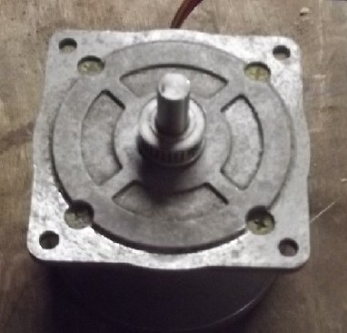
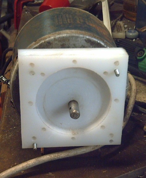 Cylinder for efficient pivoting vane
rotary air compressor
Cylinder for efficient pivoting vane
rotary air compressor
for Open Loop Air Heat Pump, mounted on 1/4 HP motor
New Chemistry Batteries
Being able to store hundreds of kilowatt-hours of
energy at affordable prices instead of lower tens would open new
modes of dealing with energy. Solar power could be stored for
rainy days, not just for overnight, both off-grid, and by
electrical utilities with mega watt-hours. EV's would be lower
cost and have longer ranges. These are immediate promises of the
new battery chemistries where the chief ingredients are abundant,
low cost metallic elements such as zinc and copper.
It occurs to me that the chemistries I've tried or
developed having been proven - Copper hydroxides, nickel-manganese
oxides, nickel hydroxide and especially everlasting
zinc-zincate, all in moderately alkaline solution, that the
project as a research project is over. The next step is production
of practical cells. I was hoping to get there, but realisticly
making batteries has proven very involved and I don't see that I
am going to be able to take it there myself.
[Longer pontification under Electricity
Storage]
New EV Motor
In a piece of highly disturbing info, in a video I
found a new type of motor that appears to be better than the one I
finally started building. I really want to build "the best". In
this new motor, the rotor uses electromagnet coils instead of
permanent magnets, yet it claims 95% efficiency. The advantage is
that the strength of the electromagnets on the rotor can be
reduced as RPM rises, allowing higher RPM's by reducing back EMF.
The tricky part is that it uses electromagnetic induction (like an
induction cookstove) to power the rotor, instead of slip rings and
brushes which are prohibitively troublesome in larger sizes like
transport motors. Well dang! After giving it some thought I
decided the stator could be identical to my present design, but
that I should change the rotor. I might even improve on it with a
hybrid "Hallbach" design having coils and still some permanent
magnets.
Some hype was also had by a lighter weight "yokeless"
motor with no iron laminates behind the stator coils. My design
with individual coils having ilmenite around the wires to complete
the magnetic circuit internally is already "yokeless" and with a
single "Hallbach" type rotor is still lighter, having (in theory -
all else being equal) only 1/4 as much heavy iron as theirs.
Being now unsure of the rotor design and in the press
of other things I didn't do any work on my motor in March. (I'll
probably want to pry off all those powerful magnets I've just
epoxied on and start over!)
[Longer pontifications under Electric
Transport]
Open Loop Air Heat Pumping
In warmer weather I ran a couple more tests with the
existing setup. I figured COP was probably somewhere between 3 and
4. But I have no means of rating it except to compare the 100
watts refrigerator (air) compressor system with a 400 watt radiant
heater and see which heats the space better. There are a lot of
variables over the length of a test.
 I have high hopes for the rotary air compressor with a pivoting
vane or flap. It promises to compress much more air with the same
power as a piston compressor. Someone made an "air engine" with
two pivoting flaps that ran 3-1/2 times longer on a pop bottle of
compressed air than any of the sliding vane models he made in the
same video. The air engine and the air compressor are virtually
the same thing with the flap reversed.
I have high hopes for the rotary air compressor with a pivoting
vane or flap. It promises to compress much more air with the same
power as a piston compressor. Someone made an "air engine" with
two pivoting flaps that ran 3-1/2 times longer on a pop bottle of
compressed air than any of the sliding vane models he made in the
same video. The air engine and the air compressor are virtually
the same thing with the flap reversed.
I came up with a good plan to power the one I've
started on and finally fitted it to a 1/4 HP motor with a 1/2 inch
shaft. The rotor spins, but much remains to be done before it's
pumping air.
[More in the detailed report]
Faraday Cabin
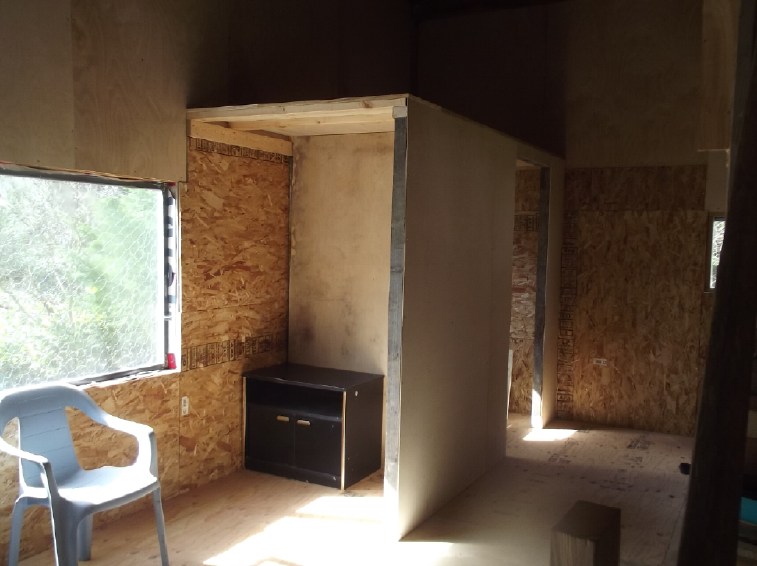 With the improving spring weather I got more work
done on the "Faraday cabin", especially the southwest quarter
including "junk" foam wall insulation, walls, plywood floor,
washroom & closet walls....
With the improving spring weather I got more work
done on the "Faraday cabin", especially the southwest quarter
including "junk" foam wall insulation, walls, plywood floor,
washroom & closet walls....
[More under Other Projects]
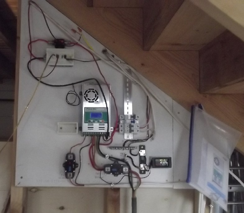
36V DC Solar Energy Improvements
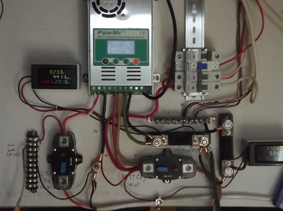 ...and some 36V DC electrical board improvements:
DIN rail branch circuit breakers replacing surface mount breakers,
and new load and charge energy monitors.
...and some 36V DC electrical board improvements:
DIN rail branch circuit breakers replacing surface mount breakers,
and new load and charge energy monitors.
[More details under Electricity Generation]
Dump Load Controller
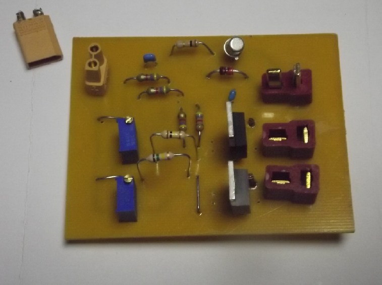 As another solar energy addition, I
tried to make a "dump load controller" to turn on heaters during
the day if there was excess solar power. I used (half of) an LM339
quad voltage comparitor to sense the switching points.
As another solar energy addition, I
tried to make a "dump load controller" to turn on heaters during
the day if there was excess solar power. I used (half of) an LM339
quad voltage comparitor to sense the switching points.
I utilized the usual 36V T-Plug system to plug the
controller into an extension cord and to have one or two
independent loads plug into the board. In order that the board
have no long wire dangling off it I used an XT30 plug for the
solar voltage sense. The solar voltage sense is 1/10th of the
actual 50-75 volts DC. The terminal strip at the electrical board
(in the above image) holds the voltage divider resistors.
But my crappy laser printer resulted in spotty PCB
traces that caused much grief in wiring and troubleshooting, and I
hadn't thought everything through very well.
Among other things there's an obvious feature I
missed: the loads should have OFF-DUMP-ON switches, since one
might want to run heaters at night or keep one load off in favor
of another.
And it didn't work as expected. Apparently the solar
charge controller uses PWM or something and the solar panels are
alternately loaded and open, so the expected steady DC voltage
actually fluctuates. As the trim pot was turned to the switching
point the load (a lamp with a DC light 'bulb') flickered instead
of being only on or off. I fixed that with a large capacitor to
smooth out the sense line. But also when it's supposed to be off
it isn't quite off - the bulb glows dimly. I haven't figured that
one out yet. (Obviously I need to get out the oscilloscope to look
for AC waveforms instead of of just a meter for DC levels.)
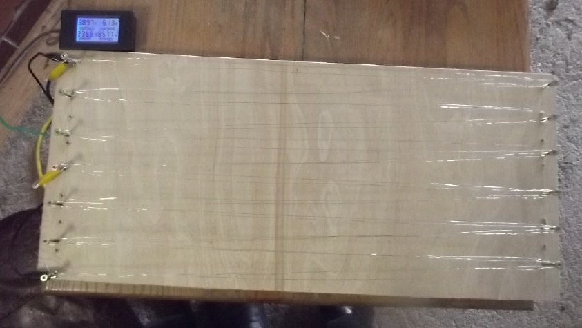 Finally, I made a 36 volt heater, or
at least, the framework of one. So far it just has an alligator
clip cord, which can be clipped onto any of the screws that hold
the doubled zig-zag wires, giving various wattages. With the
screws going into plywood, I keep it below where the wires might
start to glow, about 220 watts. It has been useful in the bedroom
in the house.
Finally, I made a 36 volt heater, or
at least, the framework of one. So far it just has an alligator
clip cord, which can be clipped onto any of the screws that hold
the doubled zig-zag wires, giving various wattages. With the
screws going into plywood, I keep it below where the wires might
start to glow, about 220 watts. It has been useful in the bedroom
in the house.
I could put alume flashing behind the wires for
radiance, but they should be thermally isolated from the
wood. Perhaps I should make some ceramic pieces? Maybe with a
screw hole and a wire hole? Now it doesn't sound like a two hour
project any more!
[More on these somewhere under Other Projects]
In
Passing
(Miscellaneous topics, editorial comments & opinionated rants)
Tinnitus
Report: Purpose of Tinnitus
[23rd] I had a logging friend come over and cut down three trees.
I was afraid of hitting my travel trailer if I cut the large one
myself. He had them down in minutes but insisted on bucking the
biggest one into firewood since he had a full tank of gas in the
saw. I had my new Stihl battery electric chainsaw so I cut off
branches ahead of him so he had only the main trunk to cut. But I
was working too close to him with no hearing protection. (He had
earplugs.) I finally went off and got my "earmuffs", but by then I
had been too exposed for too long.
For the rest of the day and the next my tinnitus was
really bad. I'm sure I did my hearing no good at all.
Probably it is "self evident" that this is what
tinnitus is supposed to be for: to warn us when we're exposing
ourselves to too much noise and damaging our hearing. If it wasn't
for the fact that electric fields also make "forever" tinnitus in
the absence of audible noise, we'd probably become more averse to
being in loud situations and preserve our hearing better. That's
just my opinion - that tinnitus has a purpose and that that's how
it's supposed to work.
It's said that 10% of the population has the
"forever" tinnitus - surely from electric power fields - and it's
probably a much higher percentage of older people. I look forward
to finishing and spending several quiet days in my "Faraday cabin"
to verify for certain that it does eventually fade to nothing in
the absence of power line EMF fields. And to see how many days it
does take.
[April 2nd] Latest report: I spent as much time as I could Sunday,
Monday and Tuesday in and working in the cabin, and I slept in it
at night. The intensity of the ringing was much reduced Monday and
especially Tuesday and the loud tone faded to a diffuse high
frequency noise. I didn't drive anywhere so I didn't get that
"right under the 14,400 volt power poles for an hour"
amplification. But I still spent too much time in the shop, the
house and in the yard too near the power lines, where I started to
notice it gradually increasing again, and it wasn't going to
vanish entirely with the repeated aggravations. Tuesday night I
slept in the house again and the tone was back in force on
Wednesday morning.
Of course I was listening carefully for these
effects. If I had been trying to ignore it to stay sane instead of
paying specific attention, probably nothing would have surfaced
from the subconscious into my conscious mind. The big change is
when it's gone entirely or virtually.
[April 3rd] Egad, more to report! Then on Wednesday (2nd) I
started doing some work in the front yard - about as close to the
power lines as I could be since my yard rapidly rises 10 feet from
the highway - so the line was as close as if I had climbed part
way up a pole. The ringing in my ears increased so rapidly that
after about 20 minutes I stopped and dragged the object of my
attention behind the lawn tractor all the way around to behind the
house and shop. Then I had to drive into town - another hour under
the power lines in the car. For the rest of the day and on into
Thursday it was really bad (despite sleeping in the cabin). The
contrast from Monday and Tuesday was so pronounced it probably
would have forced itself into my consciousness, especially if I
had worked out front for a couple of hours. And I Have had days
and nights of blaring tinnitus that I've noticed before, asking
myself "Why why why? I didn't do anything very loud!" -- surely
after days when I was working similarly close to the power lines
for extended periods.
The next week the pattern may more or less repeat.
Waiting for "don't have to drive anywhere" days and working in the
cabin. I find myself avoiding things I want or need to do just
because I know they're in zones of higher fields. Maybe I should
just hide in my Faraday cabin and become a hermit? (Have to finish
it and get internet & fone first!)
Canada
Election
I had the experience of watching one Mark Carney, a
first time candidate for any political office, pontificate for
maybe 20 minutes, sitting in a cafe that had the TV on. For the
last decade he has been governor of the Bank of England, where ex
prime minister Liz Truss said he was a disaster and that some of
the problems he caused were blamed on her. He was apparently
popularly known as "Mark Carnage". It sounds like he had to "get
out of Dodge" before the B of E collapsed under him.
Now somehow he has been magicly parachuted back into
Canada as instant prime minister, in highly suspicious
circumstances. (Remember the usual leadership race coverage? No?)
Somehow large numbers of liberals were "disqualified" from running
or even voting, and it seemed to be over almost before it began. I
heard his first speech and it sounded like all his policies were
identical to those of corrupt Justin Trudeau's and I asked myself,
"Why did we bother getting rid of Trudeau? It sounds like
absolutely nothing will change!" Then I discovered that Carney was
Trudeau's consulant all along. He and Trudeau have been associates
and friends for years and both are in Klaus Schuab's ("You'll own
nothing and be happy") World Economic Forum, espousing the same
philosophies and aims. (Hmm... I seem to recall a couple of
earlier Carneys in Liberal party political circles from the 1970s,
too. Art? Pat?) Now he has called an early snap election before we
might get to see what sort of a leader he might turn out to be.
And rather than equal opportunities, I bet the other party leaders
don't get two minutes of uninterrupted TV air time in which to say
what they want, between them. (not without the viewer being told
by the commentator sentence by sentence what's wrong with their
plans.)
I have the impression "big money" is trying to
railroad us into another four years where they call all the shots
and tell our "elected" "leader" what he is to do. Well, at least
they haven't arrested Pollievre on some trumped up charges and
told him he's disqualified from running for office, as is
happening to the leading potential future leaders in Europe right
now. (Romania, France, Turkey... Ukraine... Germany? Britain?)
Scattered
Thots
* Trump said that if elected he would
get rid of daylight savings time. "Nobody likes it." said Trump.
And yet today the computers turned their clocks ahead as usual for
the next 2/3 of the year. Has he broken his most important
political promise? Is it like Justin Trudeau promising before his
very first term, "This will be the last 'first past the post'
election."?
Or are the computers rong? Or does Trump have no say
in this? After all, the present twice extended dates were voted on
by congress. (at the behest of some deluded but persistent
congressman who thought doing so would somehow save energy, and
that that was a good enough reason everyone should get up before
the crack of dawn. Apparently if he or any of the other 500-odd
people in congress had troubled to investigate before voting, the
few statistics available indicate that using DST causes marginally
higher energy usage. Also, why did it apply in Canada with no
public discussion and AFAIK no vote?)
I'm not changing my schedule nor my clocks that
haven't changed themselves. Maybe next year, this piece of
craziness will finally end?
ESD
(Eccentric Silliness Department)
* Officer: "Why did you try to shoot Polish president Donald
Tusk?"
Suspect: "Hunting elephants is banned. I was after ivory."
(Am I actually going to leave this here?)
* What caliber was King Arthur's weapon? . . . .
.. . . .. 'X' caliber.
* I hear there's a plan afoot to make the USA into Canada's 11th
province.
"in depth
reports" for each project are below. I hope they may be useful to
anyone who wants to get into a similar project, to glean ideas for
how something might be done, as well as things that might have
been tried, or just thought of and not tried... and even of how
not to do something - why it didn't work or proved impractical.
Sometimes they set out inventive thoughts almost as they occur -
and are the actual organization and elaboration in writing of
those thoughts. They are thus partly a diary and are not
extensively proof-read for literary perfection, consistency,
completeness and elimination of duplications before publication. I
hope they may add to the body of wisdom for other researchers and
developers to help them find more productive paths and avoid
potential pitfalls and dead ends.
Electric
Transport
Unipolar
"Electric Hubcap" Motor... Revised Yet Again: Novel Rotor
Design
I chanced across a video showing a "new" type of
motor - at least, new as far as electric transport motors.
A DC motor with electromagnets in the rotor, and
brushes on slip rings to carry the magnetizing current to the
rotor, does have its advantages but, particularly in higher power
motors and at higher RPM's, the brushes and rings will arc, make
electrical noise and rapidly wear out both the brushes and the
slip rings.
The advantage is in running high RPM's. Permanent
magnets provide lots of torque, but the high, fixed back EMF
limits RPM. Torque drops with RPM as the generated voltage
approaches the supply voltage. With electromagnets on the rotor,
the rotor magnet strength can be turned down as RPM increases,
reducing back EMF. And the advantage of low and high RPM
capability is that it eliminates the need for the variable torque
converter on which I have lavished so much time and effort.
Now a company has made a transport motor that uses
electromagnetic induction to transfer power to the rotor coils
instead of slip rings. It is said to be 95% efficient in spite of
the induction losses and powering rotor electromagnets, which is
as good as any permanent magnet motor. And of course a motor with
no permanent magnets eliminates the inherent safety hazard they
present.
Oh, No! I am suddenly confronted with the idea or
truth that the motors I've been making or developing all these
years probably aren't the best possible. Then, why bother with
them? And just as I was finally building the most advanced
version! What can be salvaged if anything, and what needs to be
redone? Or should I just do other projects and forget motors?
Well, the rotor is different, but the stator can be
the same - probably exactly the same. And the unipolar motor idea
still eliminates iron magnetic hysteresis losses.
In studying electromagnetic induction, I ran across a
small DIY induction cooker that used a "U" shaped (ferrite?) core.
The heat to the pan was concentrated on the two spots at the ends
of the core. That suggests that the spinning rotor could have two
concentric rings, at the ends of the stationary "U", to receive
the energy from the primary coil.
It seems to me that on the rotor I could use the same
arrangement as on the stator: separate unit coils, wound around
iron powder toroidal cores with epoxy/ilmenite to to glue the
wires and carry the magnetic circuit. There would still be 12
coils on the stator. There would be 8 coils so 8 magnet poles on
the rotor - the usual 3 to 2 ratio.
A possible variant would be to have a cylinder
permanent magnet in the "donut hole" of each rotor coil. This
would set a minimum magnetism of the rotor and it would require
less power to energize the coils less strongly, but it wouldn't be
enough to limit the RPM to an undesirable figure. Again I would
have to figure out a good configuration for such a system, but I
got the cylinder magnets and determined mountings within the coils
for them when I was considering the "permanent magnet assist"
stator coils idea.
I could also add 8 sideways permanent magnets between the
coils to constitute it a Hallbach configuration rotor,
strengthening the field toward the stator with little field going
into the rotor disk. With the permanent magnets taking some of the
load, the rotor would require the least induced energy - perhaps
none at higher RPM's.
[14th] I didn't like all the extra variables this would throw into
an already experimental mix. I came up with another plan: the
rotor with the permanent magnets was 7/8 of an inch thick: disk
1/8 + two layers of magnets 3/8 + 3/8 = 7/8. The coils for the
electromagnet design would be one inch, plus no more than 1/4 inch
for a steel or other disk. That's just a possible 3/8 inch
difference. And insulated copper rings? Probably they would be
recessed toward the center and make no extra height.
I decided to make the permanent magnet rotor and
motor, but make the housing 3/4 of an inch longer than it needed,
to accommodate a fatter rotor when and if I get that far. First I
would get the permanent magnet version working and mounted in the
car, and tested in actual use. Later I could remove the first
rotor and try out the new one on a motor whose stator and motor
controller was already known to work.
---
I also discover that there's a name for my design
with individual coils whose magnetic circuit is completed by the
ilmenite around the windings: any such stator with no laminate
backing needed to carry the magnetic field between coils is called
"yokeless", and the idea as applied in one new motor appears to be
causing some excitement recently, largely because of the reduced
weight. But the motor in question is able to be "yokeless" by
virtue of having a magnet rotor on each side of the stator: the
"yokes" are on the outside of the rotors. With only one rotor and
it being Hallbach, my motor uses just one thin "yoke", on the
rotor, instead of two fat ones - 1/4 the iron weight. And my
unipolar motor idea still eliminates iron's magnetic hysteresis
losses. (There are probably some bad yokes about rotten eggs in
here somewhere!)
Other
"Green" & Electric Equipment Projects
"Faraday
Cabin" Construction (long continued)
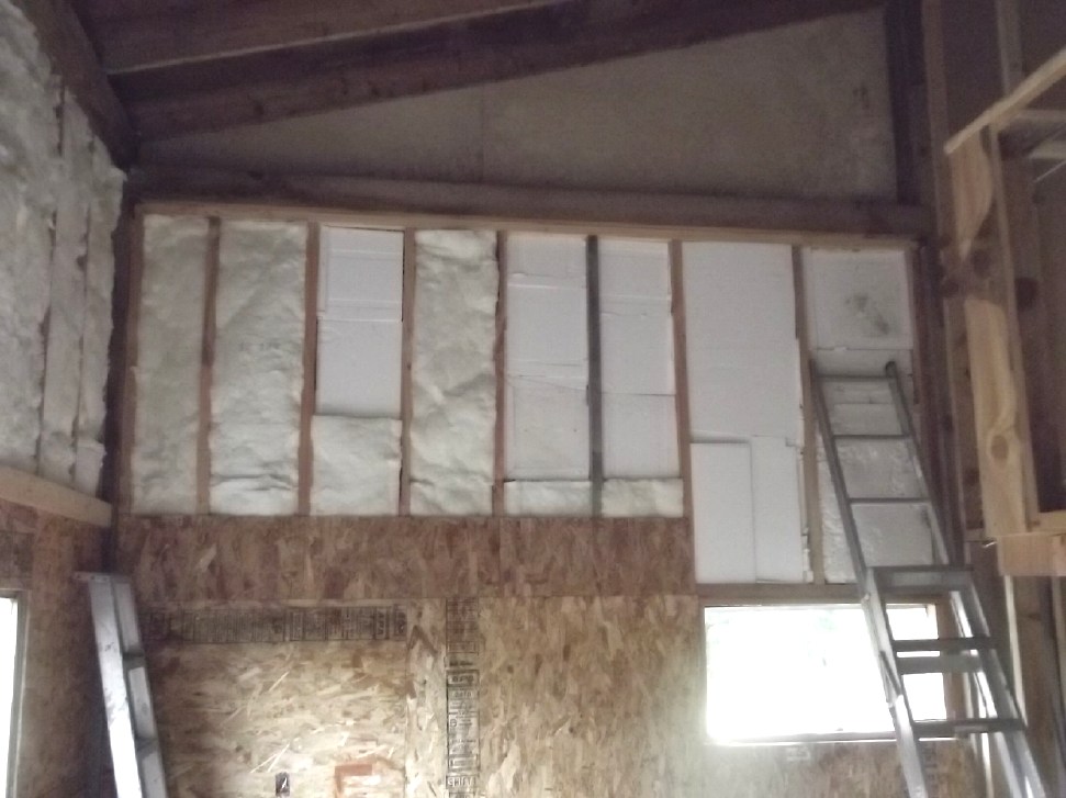
At some point I finished insulating
the southwest quarter walls with foam. (Except that gable end
way up there)
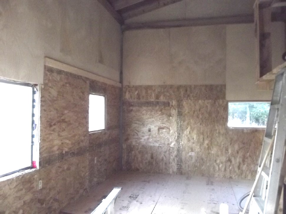
[14th] I put up the rest of the birch
wall paneling in the southwest quarter.
That's so much better than looking at ugly fiberglass (and
foam) insulation.
(I don't understand why some sheets are much darker and more
patterned than others,
except that they were probably bought at different times. I
was expecting a more homogenous appearance.)
I intend to put wallpaper on the lower "chipboard" parts.
BTW: Birch slivers are nasty!
[16th] I put insulation between the floor joists at the outside
walls in the southwest quarter [what, no picture?], did a little
caulking at the drain pipe so mice couldn't potentially squeeze in
there, and screwed down the first three sheets of plywood floor.
The walls might be a little ramshackle (and the interior walls not
done at all), but basicly it's starting to look almost civilized!
In one corner. Instead of buying more 3/4 inch fir plywood I used
up some birch plywood I already had.
The cabin's interior walls will be pretty minimal.
Four areas will be separated: the garage, the bedroom above the
garage (together filling the northwest quarter), the washroom plus
storage closet and the electrical closet under the stairs (both in
the southwest quarter). The other half I plan as "open space": the
sunny livingroom with a view (southeast quarter), and in the
northeast the woodstove area (and probably an OLAHP installation;
maybe a big water piped "sand battery" under the floor with a warm
water radiator somewhere) and probably a food prep area of sorts.
But presently I intend that my main cooking area and the bath will
continue to be those in the main house.
[19th] There was just a little piece of the southwest floor to go.
I was doing other things, but I finally said "I can't go back to
the house without cutting that last piece of plywood and finishing
the floor! So I did.
[21st] I thought if I was making the washroom walls from 2 by 3's,
that there were some used ones in the lumber piles. No one will
see them once the wall is covered, so why not use those rather
than slit more 2 by 6's in half?
I opened up the pile and discovered that they were
soaking wet. Two pieces of the metal roofing covers formed a
shallow "V" instead of both running the same way, draining all the
rain right into the wood. So I found all the 2 by 3's and took
them inside the cabin, and put a fan blowing on them to dry them
out some before using them.
At some point I reflected that I had made a mistake
in placing the stairs: I should have put the bottom end flush with
the cabin's center post instead of having the lowest three steps
sticking into the other half. The whole east half of the cabin
would have been completely clear, with the stairs, landing and
bedroom entrance themselves unchanged, just a bit farther over.
Much too late now! How little real thought went into the
placement!
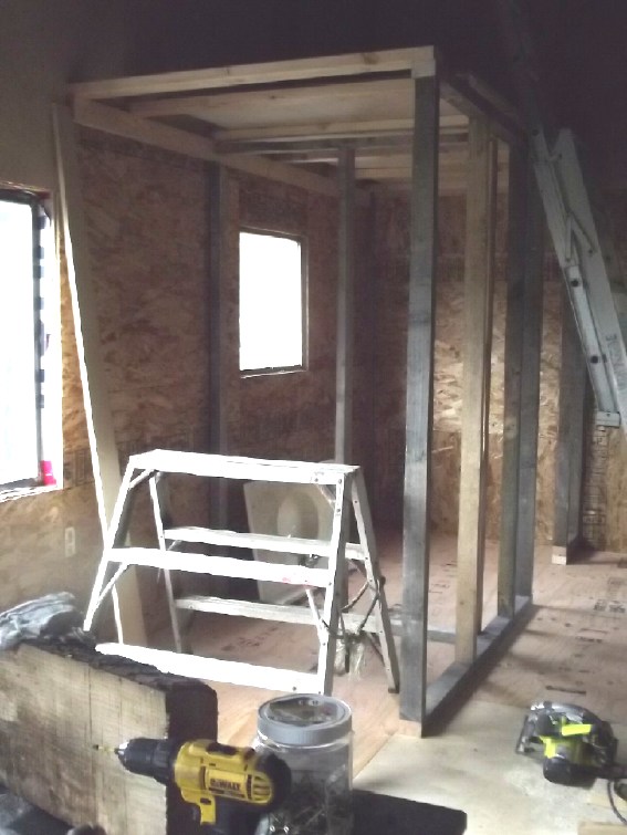 [26th?] The boards looked much dryer. I cut the
better ones to length. [27th] I screwed the wall frames together
and put them up. Then I cut and put up 2 by 4's for the ceiling
frame. With just a 4 foot span it was convenient to lay them on
their sides. [28th] I pushed up a sheet of 3/4 inch plywood for
(most of) the ceiling cover. I have the idea to store seldom used
things on this ledge above the washroom (ladder access), as well
as storage in the large closet space I made as the end section of
the washroom frame.
[26th?] The boards looked much dryer. I cut the
better ones to length. [27th] I screwed the wall frames together
and put them up. Then I cut and put up 2 by 4's for the ceiling
frame. With just a 4 foot span it was convenient to lay them on
their sides. [28th] I pushed up a sheet of 3/4 inch plywood for
(most of) the ceiling cover. I have the idea to store seldom used
things on this ledge above the washroom (ladder access), as well
as storage in the large closet space I made as the end section of
the washroom frame.
I got a ladder and climbed up. From here I could
reach the cabin roof. I'll have to put up scaffolding and insulate
that "cathedral" ceiling way up there - hopefully all of it before
next fall. I may have enough fiberglass and styrene foam already.
Later I decided to use rainwater instead of my iron
and sulfur rich well water. I could put a barrel on top of the
washroom where it wouldn't freeze in winter, and plumb it to the
eaves trough. That should suffice for hand washing.
[29th] I cut and put up 1/4 inch birch plywood for
the washroom & closet wall paneling. I used a piece that had
once been out in the lumber piles collecting rain for the back of
the closet. (At last, there's just one sheet of that left now.
It's the worst one - too ugly and degraded to use for anything
except maybe in little bits of the better parts. or firewood.)
More Foam for Wall Insulation, and the Danger of Waste Plastic
& Plastic Foam
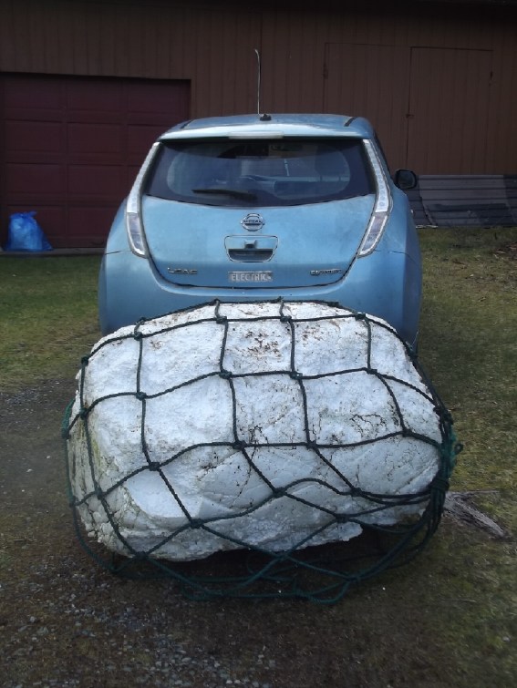 This piece of foam stranded on a beach
was visible from the highway
This piece of foam stranded on a beach
was visible from the highway
way out on a point of land. One day I went off on an expedition
and
retrieved it, dragging it through jungle and swamp to the
highway.
Amazingly I got it into the open tailgate of the car!
There was a problem: the inside seems to be a barrel, not solid
foam.
Now I don't know what to do with it. But at least it's off the
beach.
[12th] I continued to accumulate styrene foam for insulation. The
recycling centre phoned and said "you've hit the mother lode", and
sure enough I filled my trailer with 1/2 and 1 inch flat sheets.
Being out of room inside, I left most of them in the trailer for
now.
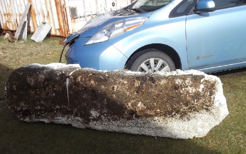 [15th] In the distance I saw what looked like a
big piece of foam washed up on a neighbor's rocky beach. I phoned.
[16th] She returned my call. It was. After my call she had tied it
so it wouldn't float away.
[15th] In the distance I saw what looked like a
big piece of foam washed up on a neighbor's rocky beach. I phoned.
[16th] She returned my call. It was. After my call she had tied it
so it wouldn't float away.
She wanted it gone ASAP. She said once she had a
chicken that stopped eating, and she had to kill it. It turned out
it had found some styrene foam on the beach and eaten the little
beads. Its belly was full of foam beads and it was starving. This
is why it's worth getting this stuff out of the environment. I
can't always tell plastic and rubber bits from clam shells and
seaweed without close examination. How are sea birds and sea
creatures with small brains and monochrome vision supposed to?
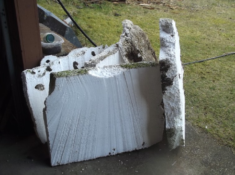 [17th] I cut it in half, there being a thin spot
part way along. I put the smaller end on the hot wire "table saw"
and cut it up. It didn't go very well. First it was wet, which
didn't help then it had a pocket of sand, and the wire didn't like
cutting through big burrowing toredo worms. One of them was almost
an inch in diameter and several inches long. That was actually
rather gory. Finally, the wire at the sides, not in the foam,
started glowing bright red with just 3-1/2 amps. Before it took
3-3/4 amps before it would faintly glow. What's changed? All I can
think is that this is the second spool of resistance wire and
maybe it's different from the first? It doesn't look any
different. The glowing wire would snap after a bit. Several times
I had to pull out the snapped wire and put a new piece on.
[17th] I cut it in half, there being a thin spot
part way along. I put the smaller end on the hot wire "table saw"
and cut it up. It didn't go very well. First it was wet, which
didn't help then it had a pocket of sand, and the wire didn't like
cutting through big burrowing toredo worms. One of them was almost
an inch in diameter and several inches long. That was actually
rather gory. Finally, the wire at the sides, not in the foam,
started glowing bright red with just 3-1/2 amps. Before it took
3-3/4 amps before it would faintly glow. What's changed? All I can
think is that this is the second spool of resistance wire and
maybe it's different from the first? It doesn't look any
different. The glowing wire would snap after a bit. Several times
I had to pull out the snapped wire and put a new piece on.
I finally put a fan on, but with the big chunk of
foam there, it could only cool one side. Finally, two fans! I had
been warm enough, but with the fans blowing I got pretty chilly.
(I could see my breath and just after I finished there was a brief
deluge of hail.) I had had more than enough for the day by the
time I finished the small end. But I wasn't able to just quit
working yet.
It was well my neighbor related to me the story about
the chicken. A lot of styro beads had rubbed off the deteriorating
float, and the barrel float too. I let my chickens out to forage
and have dust baths in the late afternoons (after the hawks seem
to have left for the day). They came around that side of the house
and started pecking away at the beads. They weren't to be
dissuaded except by throwing a handful of bird seed to distract
them. I spent the better part of an hour vacuuming up all the
little beads off the lawn. (Vacuuming. The Lawn.) Then they
started pecking at the floats themselves and breaking beads off
them. I had to roll the floats into the garage and close the door.
And then vacuum up more bits from the lawn. I am also always
picking up bits & beads of styrene foam whenever I go for a
walk on the beach; sometimes larger pieces. Along with other
plastic. No wonder sea birds and turtles are dying en-masse all
over the world!
[19th] I cut up the larger end. It was almost as much of a pain as
the first side. Several times the wire broke, and it didn't come
out very smooth. I could see not only my breath, but moisture
coming off the foam where it was being cut. And if I Stopped
pushing to be sure I wasn't about to break the wire, the stretched
wire sagged and melted downward, making far less than flat
surfaces.
I now know that I don't want any more foam floats
that have been washing around in the ocean if they are encrusted
with sea life (which takes on quite a stench after a couple of
days as it decays). Putting them in a landfill doesn't get them
out of the environment. Better to burn them if they're too
deteriorated.
Open Loop Air Heat Pumping (OLAHP)
I did two rather separate things on this: a bit of
work on the rotary compressor, and a couple more tests in warmer
weather on the present setup with the fridge compressor.
Rotary Compressor
From a theoretical design to a practical working
prototype is not necessarily a straightforward, transparent
process. Luckily starting with the rather complex "ROVACS" rotary
compressor-decompressor I didn't have confidence or time to try
making something similar, and in five years the plan has evolved
into something much simpler and far more efficient: the single
rotary pivoting vane design plus a similar but separate
decompressor or "air engine" on the same shaft, without me having
built any more complex and less efficient intermediate models.
Now that I've done some CNC on it, for starters I
thought that the pivoting vane or "flap" should have a pin for a
hinge. Maybe I should cut into the UHMW rotor and make some tiny
assembly holding the pin? But how? I finally thought of the mini
milling machine for machining it to remove small amounts
accurately, without making it a real hack job. I haven't used it
in so long it didn't come readily to mind. I didn't get any actual
work done on making it, preferring to have the rotor and cylinder
going first.
Then, I had been wondering since I made it, a few
things about how the unit was going to connect to a motor and be
turned.
[20th] I used the milling machine to make a depression in the
rotor for the bearing. I should have used a boring bar on the
lathe, because I couldn't seem to coordinate the two levers by
hand and gouged out too much, in an irregular shape. The rotor was
jamming against the innermost point of the housing. I put it on
the lathe and turned down the outside. This made it much smoother.
Just for that it was worth it. I see turning the housing to smooth
the inside of the cylinder - both rim and bottom - is also a
"must". It'll need some way to center on the lathe while the round
inner parts are turned, so it needs bolt holes for the lathe
plate. (Hmm... Actually the outer corner mounting holes as-is are
perfect.)
 As to powering the compressor, I
thought of a stepper motor and how it might attach by its face to
the compressor body piece, with the rotor simply being on the
motor's shaft and not needing any bearings of its own. But a
stepper motor was (among other things) too small.
As to powering the compressor, I
thought of a stepper motor and how it might attach by its face to
the compressor body piece, with the rotor simply being on the
motor's shaft and not needing any bearings of its own. But a
stepper motor was (among other things) too small.
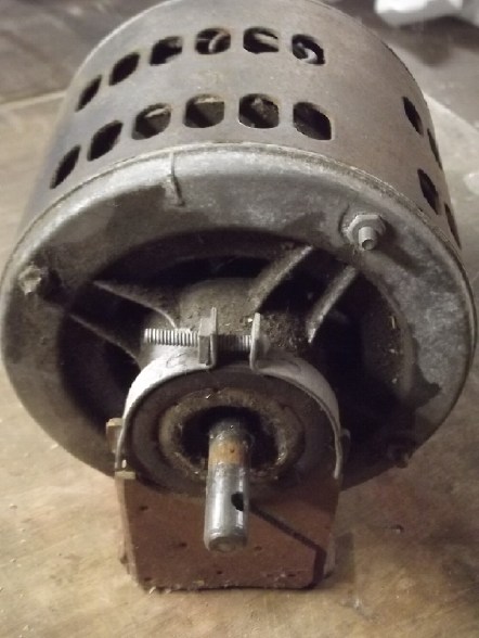 Then in the shop I dragged out an old
1/4 HP (~185 watts) washing machine motor that I had acquired from
some scrapped unit long, long ago and far, far away. If I used its
four assembly bolts and extended them out with threaded rod and
standoffs it could "face mount" to the compressor housing like the
stepper motor. All while mounted on its cushion stand, meaning the
compressor would be mounted "in the air" on the end of the motor.
Then in the shop I dragged out an old
1/4 HP (~185 watts) washing machine motor that I had acquired from
some scrapped unit long, long ago and far, far away. If I used its
four assembly bolts and extended them out with threaded rod and
standoffs it could "face mount" to the compressor housing like the
stepper motor. All while mounted on its cushion stand, meaning the
compressor would be mounted "in the air" on the end of the motor.
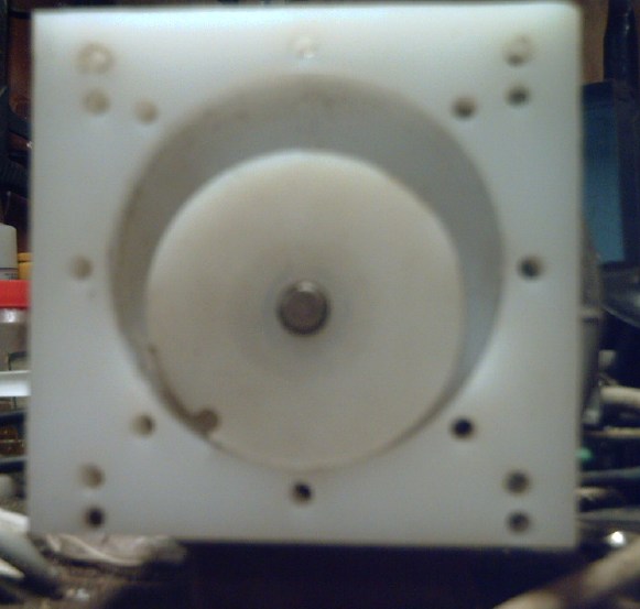
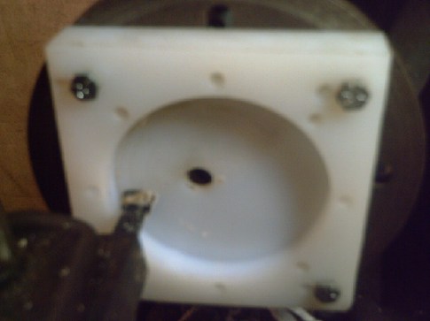
This made for a lot of clarification of what had to
be done. I would have to re-make the compressor housing with a
larger surround and the bolt holes spaced to line up with the
motor bolts. [Actually the housing proved jut large enough as it
was.] The rotor center would match the 1/2 inch motor shaft with
its flat side, and have set screw(s) to hold it on.
Somehow I didn't manage to get any
more done on it until April 3rd, when I drilled the holes to fit
the cylinder body to the motor. I managed to get the piece pretty
exactly aligned and screwed down on the CNC table so that the new
holes aligned closely with the previous routing.
 [April 4th] I continued by turning the piece on the
lathe with a boring bar, to smooth and true the inside faces of
the cylinder. Part of the bottom was a bit too deep. If I dug down
that far, the cylinder would have been thicker than the rotating
disk. As long as the disk is the fatter piece, I can put a gasket
between the lid and the outer parts. Hopefully not much air will
get by.
[April 4th] I continued by turning the piece on the
lathe with a boring bar, to smooth and true the inside faces of
the cylinder. Part of the bottom was a bit too deep. If I dug down
that far, the cylinder would have been thicker than the rotating
disk. As long as the disk is the fatter piece, I can put a gasket
between the lid and the outer parts. Hopefully not much air will
get by.
Apparently the CNC should be set not to go down quite
to the full 1/2 inch depth or the full diameter, and also to make
the rotor disk slightly oversize, so these critical faces can be
trimmed to exact dimensions on the lathe after.
I thought of expanding the center hole
of the rotor to 1/2 inch for the motor shaft, and how a twist
drill was likely to drift off center. Then I remembered I had some
step drills, and I used one with a 1/2 inch maximum step to ream
it out. That seemed to work pretty well. It was a tight fit on the
motor shaft.
I set the parts to the motor and spun it. without the
wooden pivot, which might have flown out. Seems to fit well.
Further Tests of Present (Fridge Compressor) System
[25th] It was much warmer on this morning - about 10° instead of
frost. I decided to try the existing OLAHP setup in this milder
weather. I took many readings over some hours, but the sun came
out and probably did more heating than anything else. I couldn't
swear there was any heating from the system at all. But outdoors
it was still 10°. It didn't rise above 11 all day. (or was it 12?
- shoulda wrote it down!) As with the previous tests the
temperature differences were pretty tiny. A couple of things were
notably different: First, the pipe from the compressor was warmer,
around 35° instead of upper 20's. I had to change the clamping of
the temperature probe to the pipe (the tape had gotten oily and
came loose) and I suspect it was right this time rather than
previously as it was more in line with expectations. Second, the
air coming in from the indoor-outdoor air heat exchanger was
warmer, around 20° instead of 15. This makes sense since it was
10° outside instead of 0°. I could feel the slightly cooler air
wafting out of the duct as the compressor drew air from the room -
just as it should.
Analysis
Let's look at the individual components -
The compressor was drawing room temperature air (23°), or slightly
less because it was just a short distance from the heat
exchanger's outdoor air intake duct (20.5°) to the compressor box.
So, perhaps somewhere around 22°. I measured the compressor output
pipe and hence the initially compressed air at about 34°, at 40
PSI. Probably inside the fridge compressor's sealed housing it
would be a little warmer yet, maybe around 37°. So the air was
being heated by 37-22=15°. [Hmm, that may be an underestimate?] If
it was a 100% efficient compressor the potential COP would be
296°K/15°=~20. Because we're not feeding the cold compressed air
back into a "compressed air engine" or "decompressor" to help the
compressor turn, 1/root2=29.3% of the energy the compressor uses
is wasted (as compressed air hissing to the outdoors) leaving
potential COP=14, and of course the fridge compressor surely isn't
very efficient itself. When I see the astonishing performance
difference between the (more typical) sliding vane and the (new
invention) swiveling vane or "flaps" "air engines" in the video
(TE News #201 or #200), I suspect it isn't even 50%, reducing it
to maybe COP=7. Even this doesn't seem to explain the seemingly
poor performance of the unit.
Then, the air going into the radiator was only around 28°. This is
just three feet farther down the same copper pipe from the air
compressor that was 34°, a perplexing loss of 6°. How is all that
heat being radiated off such a short copper pipe with no fins? Now
that I think about it, this is probably the most puzzling question
of all. There is air blowing out the hole in the box around the
pipe and cooling the first few inches, and the air probably isn't
traveling down the pipe very fast... but still! Is there a leak in
the pipe somewhere? (Hmm... a leak doesn't seem likely because the
pressure can build up if the output is closed off. And I'd hear it
hissing.)
The (28° going in) compressed air coming out the other side of the
room heat radiator was down to 24°, just a little above room
temperature (23°). The air blowing from the radiator into the room
was also measured as about 24°. This is how it's supposed to be,
except why isn't the air going in warmer to start with - closer to
the 34° coming from the compressor?
When I turned the radiator fan off for a while, the
compressed air out measured over 25° instead of 24°, so the heat
was still radiating off the fins to the room by convection, not
quite as effectively as with the fan on.
Finally, the compressed air (from the room radiator, 24°) going
into indoor-outdoor air heat exchanger (how about "IOHX" herein)
was coming out the other end at about 20 to 21°, having passively
warmed the outdoor air coming into the house. That air presumably
started at the outdoor temperature (~10-11°) and was coming into
the room at around 20.5°. The air was only wafting in from
outdoors, as mentioned this slight breeze could be felt at the
duct from the IOHX into the room.
On the one hand, one might think the IOHX performance
was very good because the air was so warm coming in, passively
heated by 10° out of a potential 12 or 13°. On the other, why was
the compressed air not cooled more if it was heating 10° air at
the bottom of the unit? There seems to be much wasted heating
capacity there. (Too bad it seems I didn't measure the compressed
air out in the earlier tests with 0° outdoor temperature.)
Yet More Further Tests
[27th] I ran a few more tests. It was 10° out again, but with
heavy overcast, so the sun wasn't coming in the windows to make
extra heat and mess up readings even more than usual. All other
heat in the house was turned off. There was a fair breeze that
probably caused a bit of extra air to come through the IOHX from
outside. I closed a sliding door that somewhat reduced the space
being heated. If it wasn't COP of 7, it was at least more
encouraging because at one point the room temperature was going up
instead of down.
The first test was just to run the compressor with no
fans blowing. The compressed air pipe coming out from it hit
60.2°, a foot or so out from there at the PSI meter it was 42.4°
and farther along at the input to the radiator it was down to 31°.
No sign of an air leak. At the output of the radiator the
compressed air pipe felt cool. (didn't measure)
I suspect the air flow must be fairly slow for such a
temperature drop in a few feet of pipe with no radiator fins. But
one takeaway was that I really should have some way to measure the
air flow. After all, power is proportional to volts times amps or
mass times speed or torque times RPM... or pressure times flow.
Not knowing the flow rate is a serious handicap.
With the room being 20.0°, turning the fans on got
some very warm air blowing out of the box and reduced the
compressor out pipe to 35.8°, down to 30.0° at the PSI meter and
27.0 at the rad input. After the rad it was 22.9°. The air wafting
into the room from outside through the IOHX was 18.7° - a pretty
good rise from 10° towards 20. The compressed air coming out,
having warmed that outdoor air, was down to 16.9°. From there it
is allowed to decompress and hisses out outside through a tube. If
room air is entering the compressor at 20° and leaving the house
at 16.9° (before decompression), that indicates that at least some
heat is being extracted from the outdoors into the house.
That was when I noticed the kitchen window was open
about 1-1/2 inches. Rats! Air would be drawn through that more
easily than through the IOHX. Half an hour after closing it the
room was up from 19.9° to 20.7, which said the unit was at least
putting out a little heat, but it didn't rise any further - in
fact the reading dropped by .1°.
After an hour I turned off the heat pump and plugged
in a 400 watt radiant heater. The room warmed further over the
next hour, to 21.3°.
So the heat pump brought the temperature up by .8° in
1/2 an hour but no further in the next 1/2 hour, and and the 400W
heater raised it by a further .6° in an hour. So perhaps they were
about equally effective? That would give the heat pump with the
100W fridge compressor a COP of around 4. That would seem
reasonably consistent with my 2020 results where COP with a small
fridge compressor was around 3 in zero degree weather.
I turned all heat off and the temperature
dropped in over an hour to 20.1° - a 1.0° drop. Then I left the
heap pumping on for about 3 hours. The temperature dropped from
20.1° to 19.2°, but the outdoor temperature had dropped from 10 to
8°, so it might actually have been a bit of a gain, depending when
it got colder and on the thermal inertia of the room.
But there's still another wild card in getting exact
readings: the refrigerator. I couldn't turn it off safely. (I'd
forget!) It uses 120 watts and itself has a COP probably of around
3 or better, so whenever it comes on (frequently) it adds 360+
watts of heat to the room. That's almost as much as the heater and
seemingly similar to the heat pumping. The rest of the time, cold
is leaking out of the fridge. That's why I don't feel any of the
readings, however accurate the temperature sensor, are totally
definitive. Of course it should average out, but not always in a
one hour test.
[30th] On line I found something like a short piece of pipe with
inside threaded ends and an LED display for 45$. It said it was
for measuring liquid flow, but one reviewer said he found them
great for 'various liquids and gasses'. So I'll hope it works for
air.
A "dump load" is
something for an off grid solar or wind power system to power when
there is an excess of energy. In the case of wind power, it is
necessary to use excess power to prevent the propeller from
over-revving in high winds. For solar it's just a way to use
available excess energy rather than letting it go to waste. One
could for example heat a "sand battery" or hot water for later, or
just run an electric heater for free.
[14th] Before designing a circuit to control dump loads, I checked
on line. Some people suggested using a microcontroller. I found an
opamp circuit and it worked as I had envisioned, by measuring the
voltage on the solar panels to see if it was above MPP, which
would mean the charge controller wasn't drawing all the available
power because the battery didn't need it. But it seemed needlessly
complex, so I designed my own anyway using an LM339 quad voltage
comparitor. It could run up two "dump loads" independently so one
could have one load for a little excess power and another, perhaps
larger, if the voltage still got higher indicating the solar
panels had still more power available.
[18th] In the evening I started laying out a circuit board. [19th]
I spent most of the day on it. I ended by printing out the board,
finally trying out the fingernail polish remover method I had seen
on Youtube of transfering the the print from glossy magazine paper
to the copper board. It sort of worked but it looked too faint,
and there was still toner on the paper. I didn't give it much hope
for good etching. Either my technique wasn't good or the remover I
had was a different formula.
It's been a long time since I made a board. Even a
"simple" single sided PCB seems to take just as long as ever and I
wondered at the wisdom of the undertaking, "wasting away" the day
sitting at a computer and then still having to make the board and
install it. But, "in for a penny, in for a pound", I might as well
complete it and have it working.
 [22nd] So after searching three times through my
stationary supplies and even throwing a bunch out, I finally found
my "fab in a box" heat ransfer paper and did it that way. Even
there, it wasn't much of a board.
[22nd] So after searching three times through my
stationary supplies and even throwing a bunch out, I finally found
my "fab in a box" heat ransfer paper and did it that way. Even
there, it wasn't much of a board.
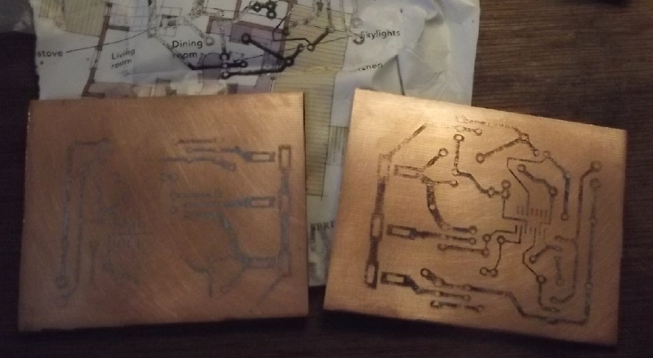
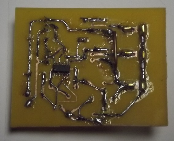 I'm sure my laser printer, in spite of being set
to "darkest, maximum contrast and high quality", just doesn't put
down half enough toner on the paper. And it's obviously getting
worse. The traces, and then the copper on the etched board, looked
fairly solid but there were minute gaps with disconnects here,
there and everywhere. When putting the components on, I didn't
clip off the leeds. Instead I bent them over to reinforce the
copper run on the board and soldered them to the trace.
I'm sure my laser printer, in spite of being set
to "darkest, maximum contrast and high quality", just doesn't put
down half enough toner on the paper. And it's obviously getting
worse. The traces, and then the copper on the etched board, looked
fairly solid but there were minute gaps with disconnects here,
there and everywhere. When putting the components on, I didn't
clip off the leeds. Instead I bent them over to reinforce the
copper run on the board and soldered them to the trace.
[23rd]
I drilled the holes in the board with a "dremmel". [24th] I put
the components on the board. As I was finishing this up and
thinking about using it, a couple of things occurred to me. If I
was to connect the same heater(s) that I usually used for heat at
night to turn on as "dump loads" in the sunshine, then each load
should have an "ON-DumpLoad-OFF" switch. Otherwise they would have
to be unplugged from the controller and into an "always on"
receptacle at night. (Or whenever they were to be used.)
The other thing was that since it was an automatic
control with mosfet switching anyway, it should shut the loads off
if the battery was low. There are two spare voltage comparitors on
the LM339 anyway. The first feature would be simple. The second
might require a logic AND gate. OTOH one might get away with using
the fourth comparitor and a couple more resistors?)
[30th] While it was light out
I also added the solar PV voltage sensor for the dump load
controller, and plugged in the controller. I found a couple of
things not right and changed them. But then a mystery... The lamp
("dump load") I plugged in was On, but the voltages to the LM339
gate indicated it should be Off, the "-" input being higher
voltage than the "+" input. The gate's output was High (turning On
the mosfet and the lamp) instead of Low. It turned out there were
multiple problems. I printed out the schematic and the board for
troubleshooting. By then I had other things to do.
[31st] I worked troubleshooting the dump load controller most of
the day. I would have just thrown in the towel, except each
problem looked like it would be the last one, so best not to quit
just short of success. The majority were owed directly or
indirectly to bad connections, which were from the printer not
printing dark enough and making a PCB with dotty traces.
Once I had solved a bunch of them I thought I'd be
there, but then I just sat there looking at it. The lamp test load
would flicker instead of just suddenly coming on, and then it
wouldn't quite go out. I tried a 200 watt heater, and the mosfet
started smoking. I managed to unplug the heater before something
blew. I'm sure it got so hot because of being not quite off, same
as the lamp. Then the 400W heater upstairs came on (I could hear
its fan) and the solar voltage reading went UP in instead of DOWN,
from about 70V to 74V, and the test lamp came ON with the heater
instead of OFF! That seemed bizarre, and I had the thought that
the charge controller was drawing current with some sort of PWM
and while its meter showed stable, so it was probably putting
spikes into the solar voltage. This is the voltage I'm sensing to
decide when optional loads turn on and off? I put a 220uF
capacitor on the solar sense input at the PCB. That fixed the
flickering as the lamp came on, but it still wasn't turning right
off. Instead, the LM339 output read about 3VDC instead of 0V or
12V (Vcc). Also only one of the two seemingly identical dump
controllers worked. The other wouldn't turn the lamp off. What was
with that one when the voltages all seemed good, same as the other
one? I guess I need to drag out the oscilloscope to better see
what more bizarness is actually going on.
I hadn't expected this to be any sort of significant
project. A "couple of days" stretches out and I'm not getting my
spring seedlings potted. or anything else - and in nice weather
before the biting bugs start coming out, too.
[April 1st] The thought "ground loop" had occurred to me, but it
seemed insufficient as a possible explanation. After working on
the cabin and other things, I sat in the cabin with a glass of
wine across from the electrical board. Then it occurred to me that
the sense lines had the solar panel ground, solar "+" and "-".
(This is actual ground via a ground rod.) The board plugged into
power, "B+" and load ground, which was two current sensing
shunts away from solar ground. There could easily be 30 or 50 mV
difference, but they were shorted together in and by the circuit
board. This probably explains some of the craziness. The sense "-"
needs to go to the same "-" that's powering the board.
Resistance Wire Radiant Heater
[9th?] I thought it should be simple enough. Use
a 2 foot long piece of plywood and put lots of screws at each
end, then zig-zag it all with resistance wire. But I wanted to
use lots of length so the wire didn't glow red and sag and the
screws didn't get too hot. The wires sagged enough anyway when
heated that I moved the screws farther apart, from 1-1/4 inches
to 1-2/3 so they wouldn't touch adjacent wires. (I also wrapped
the wires 1-1/2 turns at each screw instead of 1/2 a turn to
give them more resilience.) I ended up doubling up the wire and
still it was lower power than I had planned - 68 watts across
the length. I could however attach the power to any of the
screws, and the shorter the wires, the higher the power. If I
put one power connection to the middle screw, putting the other
on one end made 100 watts and the other end made 120. So with an
alligator clip between the two end screws it was 220 watts. Then
with the middle power connection moved to the other end... ouch,
a big spark! Oh ya, the cross connection between ends. I burned
out a couple of the heater wires. Rats! I got them together
again and continued. I could connect across less than half the
length and get 220 watts, or 440 by doubling - and quite hot
wires.
I should probably try tripling the wires. The
plastic foam "hot knife" saws hadn't used much of the resistance
wire. The doubled heater wire had used up a whole spool, so
tripling it would be another half spool.
Bedroom Heat
With the workings of a 100/120/220 watt DC heater.
(hardly a finished product!), on the 10th I set it in my bedroom
on top of the "sand battery" box near the 36V triple outlet.
With the days now recharging the battery even when partly cloudy
I continued to run the 200 watt heaters from the 36V DC
(150+50+50 as ~1/10th their 120V AC rating). I had been using
them to supplement the baseboard heat. Now and on subsequent
nights I also plugged in the new heater. With 350 or 470 watts
of heat from the batteries the bedroom stayed up at 18 to 20C
without using the baseboard heater at all. I was a bit surprised
it kept up that well as the nights were still cold - around
freezing with frost in the mornings. They were using about 3.5
to 4.5 KWH per night, with the solar recharging the battery the
next day. 470W is pressing the 15 amp breaker on that outlet.
Redoing it I would put in a 20 amp breaker, preferably in a DIN
Rail breaker system.
Assuming the battery lasts many years and that it's
sufficient heat, this is actually better than a typical
grid-tied solar system as there is no solar power during the
night so bedroom/nighttime heat would always come from the power
grid. But I should add a thermostat and either auxiliary power
to the DC or a low voltage cutout in case the battery gets low
unnoticed. At the last gasp the balance charger should
disconnect the battery if any cell falls below 2.5 volts, but
that's awfully low. I'd rather have it cut out around 3 volts on
any cell.
Of course if one incorporates a battery one can
have a more sophisticated grid tied system with an
inverter/charge-controller where power comes from a hierarchy.
In its simplest form:
1) Solar if available
2) Battery if charged & there's no/insufficient solar
3) Power grid if there's nothing else
and available solar power goes to:
1) Charging the battery if it isn't charged
2) The power grid if the battery is charged
This assumes the battery is only or mainly charged from solar
rather than from the grid. Other arrangements are possible, such
as using batteries at times of day when grid power costs more
and charging them from the grid when it's cheaper regardless of
solar, in jurisdictions where such variable rates are used.
[14th] I had to get used to the voltage levels. Before, under 38
volts meant the battery was quite low. But the voltage drops
more under higher load. When I turned on the 250W of heaters,
the voltage would drop from (eg) 39.6 to 39.0V or under 39. By
morning it might be around 38.5. When I also connected the new
heater with a further 100 or 220 watts, the meter in line with
that heater would drop to 37.X, and I had to 'reorient' my
thinking, that it wasn't suddenly at a low charge, just under a
heavier load than "usual". (And a somewhat skinny wire to the
heater.) Unless the battery started out low, it would stay above
37V all night, and jump back to over 39V when the heater was
turned off.
But after 3 nights I decided that 470W for the
night was a bit much, draining the battery as much as half way.
So I stuck to 350 watts, which made for about 3-1/2 KWH used per
night and didn't drop it below 38. The bedroom seemed to stay
around 18.5°.
There was solar power to burn most days for a
couple of weeks. Now I thought to plug in the sand "battery". It
stores the better part of 1 KWH, which could be added at night
to the 3.5 KWH from the battery battery to make it a bit warmer.
A bigger pail holding more sand would of course be more useful.
Sand is cheap. Or a bigger actual battery - really 10 KWH
doesn't go very far. I could see them being cheap enough to want
double or triple that or more if battery prices keep dropping
while the price of grid power rises.
And of course, this is another plug for really
cheap copper-zinc or nickel-zinc moderately alkaline cells if a
manufacturer will adopt my chemistry(s). Then one might
economicly want 50 or 100 KWH of storage. After all this time I
don't see how to manufacture them myself - I'm having trouble
even getting the forces and forms needed to compact nickel
electrodes sufficiently to make them work properly. But surely
the time will come.
Electricity Storage
Copper Oxyhydroxide
or Nickel Oxyhydroxide
or Nickel-Manganese Oxides
& Zincate Cells
Low Cost Electricicty Storage
With the advent of low cost solar panels, it is now
possible to capture plenty of energy from the sun in lower
latitudes, and for much of the year in higher latitudes too. It is
well known that storage of electricity is now the biggest handicap
to "going off grid".
I've purchased two sets of 10 KWH batteries for under
about 2000 $C each. (12 * 286 AH * 3.2V = 9627.2 KWH). This is
sufficient for lighting and limited power applications. Except in
winter I can run 3 or 4 KWH of bedroom heat at night, and more
during the day when the sun is shining. It would be somewhat
better at a lower latitude. But even for that bit, two cloudy
winter days with little recharge would tax the battery and three
would kill it. and there's lots of things I wouldn't even try.
For example, my Nissan Leaf electric car has a 24 KWH
battery pack, and that's not half of what any new EV has. I
wouldn't normally try and recharge it from my solar/battery
systems because unless watched "like a hawk" it might drain the 10
KWH battery entirely and cause problems as well as turn off the
electricity. I might say I would charge the car if I had a well
charged 30 KWH storage battery, considering the car isn't likely
to need more than 20 KWH on any particular occasion. For a new car
the figure well might be 70 to 100 KWH. Likewise, I might run
sufficient electric heat for a house for the whole day instead of
just a bit in one room. And heat hot water and use a clothes dryer
- power intensive functions. Heating hot water is a wild card
because it can come on any time day or night, whether the battery
is well charged or not. The more storage there is, the easier
things get. With just 10 KWH one must be very careful not to drain
the system overnight. With 100 KWH one would have a margin of days
instead of hours and could say (eg) "I shouldn't do laundry today"
or "We should light the woodstove today instead of using electric
heat." if capacity is down, without worrying that the refrigerator
or the hot water tank will drain the system in regular operation.
But if 10 KWH of lithium-iron phosphate cells is 2000
$, 100 KWH is pretty unaffordable. This is why we need low coast
batteries like copper-zinc. A safe 2000 $ battery needs to be 100
KWH instead of 10. Like everlasting copper-zinc (or
nickel-manganese oxide-zinc or even nickel-zinc). Then we will
start seeing lots of people going off grid, and we will see the
grid itself storing huge amounts of energy to have many hours or
even days of storage for whole communities. I've made the
zinc/supersaturated zincate "forever" cycling chemistry, but I
don't see how to manufacture actual practical cells. That needs a
big investment in a real factory.
(Think of hundreds and thousands of kilowatt-hours of cheap, safe,
"forever" energy storage instead of tens and hundreds of costly,
unsafe cells with a few years of service life. I've proven the
everlasting zinc-zincate chemistry, with a choice of at least
three positive electrodes. Really the project needs to go to some
sort of production processes. I can't take it there myself.)
My Solar Power System(s)
(My solar panels images - TE News #200)
A little note on the safety & efficacy of 36 volt house
wiring
May I once again suggest "36" volts is the optimum
wiring voltage for living spaces? For all my sloppy carelessness,
especially plugging in soldered plugs with no shells and with my
fingers directly touching both terminals, I've had sparks but I've
never had the slightest shock from the 36-41 volts of DC power.
The one caveat is that this has generally been indoors in a dry
environment.
A 48 volt system, which might actually measure up to
57 volts or so fully charged, is said to be somewhat hazardous.
Various national standards put "hazardous" voltage as starting at
42 or 50 volts. "36" volts with a well charged battery comes just
about up to the start of the lower figure. At 36 volts, running 20
amp circuit breakers and common #12 AWG wire with typical small
electrical boxes to T-plug wall sockets allows running plug-in
appliances up to almost 700 watts, nearly one horsepower.
So on the one hand, why have hazardous voltage
running all over the house and in every cord and every appliance,
and on the other, why use a needlessly low voltage that requires
higher currents and very heavy wiring for power loads? 36 volts is
the upper limit of non-hazardous, but it Is non-hazardous in any
normal conditions. (Gripping a part being welded with 36 volts
while standing in salty water in a cramped boat hold doesn't count
as "normal"! Even then the guy lived to tell me the story.) And
why use AC when the 60 Hz oscillating electric fields somehow
trigger continuous tinnitus in so many people, and other health
concerns whose cause is (usually?) not understood according to
GreenHomeInstitute.org ?
Today there are reliable devices and circuits for
converting between voltages and between AC and DC, so why should
we accept anything that is hazardous or deleterious for our health
in and around our living spaces?
Solar Power System Additions
 [14th] I had got two new power monitors, and I
went to put the second one in the cabin, where the present one was
monitoring the load rather than the charging. Functioning on some
sort of autopilot, I simply replaced that one with the new
external shunt one that could measure higher currents. Wait... I
thought this one was to measure the charging!?!
[14th] I had got two new power monitors, and I
went to put the second one in the cabin, where the present one was
monitoring the load rather than the charging. Functioning on some
sort of autopilot, I simply replaced that one with the new
external shunt one that could measure higher currents. Wait... I
thought this one was to measure the charging!?!
Oh well, the currents were exceeding the 20 amp limit
of the first monitor and I'll probably add more loads, so it did
need replacing. So I left it like that. I went into the house and
ordered a third monitor and shunt, and a couple more things from
the same store while I was at it. When the new one comes, it can
measure the charging.
[30th] The new power monitor and two 100 amp shunts having
arrived in my post box, I put one shunt onto the cabin power
monitor where I had been using a 50 amp shunt and dividing the
readings by two.
 I mounted the other one
by the 3D printed case already mounted for the power monitor for
the solar charging circuit. I thought this time I would directly
monitor the solar panels where they fed into the charge
controller. I wired up as much as I could without cutting into the
75 volts from the solar panels for the shunt. That I did after
dark when there was 0 volts from the panels.
I mounted the other one
by the 3D printed case already mounted for the power monitor for
the solar charging circuit. I thought this time I would directly
monitor the solar panels where they fed into the charge
controller. I wired up as much as I could without cutting into the
75 volts from the solar panels for the shunt. That I did after
dark when there was 0 volts from the panels.
Only when I turned the breaker back on and the
monitor remained blank did I realize there was a fly in the
ointment: the voltage sense wire was also the power for the
monitor. In the evening when I came to read the day's accumulated
solar intake, the display would be off! Oops; duh! And if I
powered it from the battery, the voltage wouldn't match the
current and the watt-hours would be wrong. I would have to redo it
- cut the ground wire from the charge controller to the battery
and put the shunt there, with meter power coming from the battery.
And splice the ground wire from the solar panels back together
where I removed the shunt. Ug! Clearly I'm not giving enough
thought to what I think of as "trivial" projects. My mind glosses
over the details (where the devil is said to lie) and I keep
making mistakes.
[April 1st] I moved the current shunt from solar panel ground to
"B-" battery ground and rewired the power monitor.
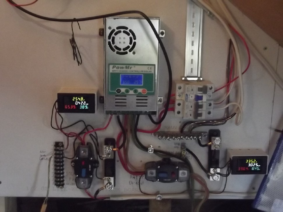
The 36V DC electrical board as finally
wired.
Note the new DIN rail breakers replacing the previous surface
mounted branch circuit breakers.
DIN rail are the standard breakers in Europe - usually in a
metal box of course because it's 230V AC.
The only drawback to these versus North American proprietary
breaker boxes and breakers
is having to somehow "daisy chain" the line connection common to
all the breakers.
From a video I gather there's usually a bare metal bus bar, like
the ground
and neutral bars but with the 230 volts openly exposed in the
box. (workers beware!)
I may adopt that too, but with 36V DC
The Usual Daily/Monthly/Yearly
Log of Solar Power Generated [and grid power consumed]
Notes:
* All times are in PST: clock ~48 minutes ahead of local
sun time, never PDT which is an hour and 48 minutes ahead.
* Unapproved AC/Grid Tied systems have been removed.
* DC meters accumulate until [before] it loses precision (9.999 WH
=> 0010 KWH), then are reset - hopefully before that. (Suddenly
losing THREE decimal places of precision is Not helpful!)
* House panels include four old ones on the roof (upper - total
rating ~ 1000W), two 305W on the roof, three 305W on the south
wall below the roof, and one broken panel mounted verticly on the
porch railing (seems to still work but a lot of shade there).
* Cabin meter is reading LOAD KWH, not SOLAR KWH. These are
eventually the same thing, since the solar charges the batteries
for the load, but not directly indicative of a sunny or cloudy
day. (I may put a meter on the charging some day!)
* Cabin DC includes the three carport panels and the two on a pole
in the yard as well as the four on the cabin roof itself. All nine
are 305W.
* The wall, pole and porch panels are easily wiped off from the
ground if it snows.
* Km = Nissan Leaf electric car drove distance, then car was
charged. Car KWH does not add to or subtract from any other
readings.
Recent fotos of solar panels: TE News #200
House System Panels: House roof, wall (9 solar panels) -
Porch (1 broken one - usually shady)
Cabin System Panels: Carport (3 - sunniest place on
the whole property) - Pole (2 - shadiest place) -Faraday Cabin (4
- badly shaded in winter)
New Order of Daily Solar Readings (Beginning November 2024):
Date HouseDC, CabinDC => Total KWH Solar [Notable power Uses
(EV); Grid power meter@time] Sky/weather, notes...
February
28th 5.14, 1.67 => 2.99 [85Km; 24733@19:00]
March
1st 7.74, 1.72 => 2.65 [60Km; 24833@'24:00';
50Km]
2nd 11.24, 4.41 => 6.19 [24881@19:00] Mostly sunny. (New
meter goes past 9999 WH, yay!)
3rd 14.61, 6.30 => 5.16 [60Km; 24949@18:30]
4th 15.90, 7.64 => 2.63 [25009@18:30] Dull again.
5th 20.71, 12.5 => 9.67 [24069@18:30] Really sunny!
(12.5°... somewhere between 11 and 13!) The batteries were a bit
low and absorbed some KWH, but I ran heaters all day. (Starting at
5° in the morning, the cabin bedroom hit 20° before the end of the
day with 750W of solar heat on.) Often the 'PowMr' charge
controllers were doing over a kilowatt. For the first time I can
remember their cooling fans came on. I tried grafting onto apple
and pear tress - 6 grafts in all. I planted the black walnut. I
started 'cold stratifying' some birch and black locust tree seeds
that I bought many moons ago. Someone mentioned that they might
become invasive species. I'm more concerned with putting wire
around every one of them so the deer don't nip off the saplings at
the ground. I doubt they will spread without help. Almost the only
softwood on these islands is red alder - perhaps because the deer
don't seem to like it.
6th 21.93, 1.29 => 2.51 [25127@18:30] Cloudy again
7th 26.76, 4.17 => 7.71 [25186@19:00] & today mostly
sun
8th 31.02, 6.43 => 6.52 [110Km; 25262@23:30]
9th 35.49,10.44=> 8.48 [45Km; 24317@19:00] (Cabin reset
to 0 twice for this >9.99 KWH reading.)
10th 39.46, 3.62 => 7.59 [25371@23:00]
11th 43.25, 6.25 => 6.42 [25422@19:30]
12th 47.90, 3.00*=> 7.65 [50Km; 25483@19:00] *(New [load side]
power monitor in cabin - 5 KWH digits instead of 1.)
13th 53.00, 7.37 =>10.47 [--?]
14th 56.27, 9.76 => 5.60 [90Km; 25613@19:00]
15th 61.14, 12.17 => 7.28 [55Km; 25679@20:30; 50Km]
16th 65.42, 14.61 => 6.72 [25725@19:00]
17th 69.45, 16.92 => 6.34 [25784@19:00]
18th 72.31, 19.09 => 5.03 [55Km; 25848@19:00]
19th 73.08, 20.35 => 2.03 [25896@19:30]
20th 77.18, 22.58 => 6.33 [25965@19:00]
21th 80.62, 24.54 => 5.40 [26034@19:00]
22th 82.50, 27.12 => 4.46 [55Km; 26102@21:30; 50Km] Clouds,
rain
23th 86.92, 28.21 => 5.51 [45Km; 26163@19:30]
24th 90.65, 29.81 => 5.03 [26220@19:00]
25th 95.27, 33.21 => 8.02 [26272@19:00]
26th 101.44, 38.49 =>11.45 [26312@19:30] Sunshine!(& I ran
lots of heaters!)
27th 103.29, 41.55 => 4.91 [25357@19:00] NOT sunshine!
28th 107.48, 44.54 => 7.18 [85Km; 25413@19:00]
29th 110.66, 49.63 => 8.27 [55Km; 25480@20:30; 50Km]
30th 115.07,53.29*+1.50*=>9.57 [26544@19:30]*Meter had to be
reset during day owing to wiring change.
31th 120.27, 5.10* => 10.3 [26593@18:30] *New power
monitor, this one measuring CHARGE instead of DISCHARGE.
April
1st 123.71, 10.84 => 9.18 [26651@19:30] Part sun.
2nd 128.10, 16.26 => 9.81 [55Km; - ]
sun
3rd 131.34, 23.87 => 10.90 [26772@19:30] sun
4th 133.84, 27.69 => 6.32 [26835@19:30]
clouds, wind
5th 135.02, 31.78 => 5.27 [55Km; 26911@20:30;
50Km]
6th 138.60, 38.51 => 10.31 [26979@19:30] some sun
7th 141.79, 44.88 => 9.56 [27032@21:30] not much
sun
Chart of daily KWH from solar panels. (Compare March 2025 with February 2025 &
March 2024.)
Days of
__ KWH
|
March
2025 (18
Collectors, DC/
Batteries only)
|
February 2025
(18 C's - DC/
batteries only)
|
March 2024
(18 C's - Grid
Ties & DC)
|
0.xx
|
|
4
|
|
1.xx
|
1
|
1
|
|
2.xx
|
4
|
8
|
1
|
3.xx
|
|
7
|
1
|
4.xx
|
2
|
2
|
1
|
5.xx
|
5
|
4
|
2
|
6.xx
|
6
|
1
|
8
|
7.xx
|
5
|
1
|
|
8.xx
|
3
|
|
4
|
9.xx
|
2
|
|
1
|
10.xx
|
2
|
|
|
11.xx
|
1
|
|
|
12.xx
|
|
|
2
|
13.xx
|
|
|
|
14.xx
|
|
|
|
15.xx
|
|
|
3
|
16.xx
|
|
|
|
17.xx
|
|
|
|
18.xx
|
|
|
1
|
19.xx
|
|
|
2
|
20.xx
|
|
|
1
|
Total KWH
for month
|
202.54
|
94.43 |
337.81 |
Km Driven
on Electricity
|
1162.9 (@7.5
Km/KWH)
= 155 KWH
|
682.7 Km
~100 KWH |
1049.1
(~~140 KWH) |
Things Noted - March 2025
* Weather definitely brighter than Feb. as well as warmer.
* It is apparent from March 2024 (337.81 KHW) versus March 2025
(202.54 KWH) figures that without grid ties harvesting all the
available solar energy, much is being wasted on sunny days once
the batteries are charged.
* [31st] Yay, a proper charge monitor on the cabin system! (One
with 5 KWH digits instead of one, too!)
Monthly Summaries: Solar Generated KWH [& Power
used from grid KWH]
As these tables are getting long, I'm not repeating the log of
monthly reports. The reports for the first FIVE full years (March
2019 to February 2024) may be found in TE News #189, February 2024.
2024
Month: HouseAC + DC +Carport+Cabin[+DC] (from Aug 2024)
Jan KWH: 31.37 + 3.14 + 16.85 + 16.82 = 68.18
[grid power used: 909; car (very rough estimates): 160*]
Feb KWH: 96.52 + 2.36 + 49.67 + 52.98 = 201.53 [grid: 791;
car: 130]
FIVE full Years of solar!
Mar KWH 150.09+ 1.63 + 93.59 + 92.50 = 337.81
[grid: 717; car: 140]
Apr KWH 181.89+35.55 +123.50+142.74 = 483.68
[grid: 575; car: 140]
May KWH 129.23+67.38 +109.6 +126.32 = 432.53
[grid: 405; car: 145]
Jun KWH 152.54+51.02+118.99+141.17 = 463.72
[grid: 420; car: 190]
July KWH 174.22+30.53+111.19+128.62 = 444.56
[grid: 386; car: 165]
Aug KWH 221.99+ 2.63 +142.49+151.67+ 5.78 = 524.56 [grid:
358; car: 180]
SeptKWH 120.98+ 2.49 + 83.50 + 19.10+ 39.95 = 266.02 [grid: 662
(yowr!); car: 155*]
Oct KWH 78.48+ 7.29 + 64.39 + 7.52 + 40.75 =
198.43 [grid: 711; car: 120*]
Nov KWH 19.63+12.19+ 23.90 + 3.35 + 25.62
= 84.69 [grid: 900 (ACK!);car: 110*]
Now solar is charging
batteries only. 2 DC systems: house, cabin.
Dec KWH 20.37 + 16.76 = 37.13 [grid: 1866 (using electric
heat!); car: 120*]
2025
Jan KWH 35.02 + 26.30 = 61.32 [grid: 2136 (electric
heat OW!); car: 120*]
Feb KWH 55.43 + 39.00 = 94.43 [grid: 1937; car: 100*]
SIX full Years of
solar!
Mar KWH 115.13 + 87.41 = 202.54
[grid: 1860; car: 155* KWH]
* Car consumption comes from solar and or
grid: it does not add to other figures. (Just from grid from
Nov. 18th. 2024 on)
Annual Totals
1. March 2019-Feb. 2020: 2196.15 KWH Solar [used 7927
KWH from grid; EV use: -] 10, 11, 12 solar panels
2. March 2020-Feb. 2021: 2069.82 KWH Solar [used 11294 KWH from
grid; EV use: - (More electric heat - BR, Trailer & Perry's
RV)] 12 solar panels
3. March 2021-Feb. 2022: 2063.05 KWH Solar [used 10977 KWH from
grid; EV use ~~1485 KWH] 12 solar panels, 14 near end of year.
4a. March 2022-August 2022: in (the best) 6 months, about 2725 KWH
solar - more than in any previous entire year!
4. March2022-Feb. 2023: 3793.37 KWH Solar [used 12038 KWH from
grid; EV use: ~1583 KWH] 14, 15, 18 solar panels
5. March 2023-Feb. 2024: 3891.35 KWH Solar [used 7914 KWH from
power grid; EV use: ~1515 KWH] 18 solar panels
6. March 2024-Feb. 2025: 3428.88 KWH Solar [used 12773 KWH from
grid; EV used: ~1685 KWH]
Money Saved or Earned - @ 12¢ [All BC residential elec.
rate] ; @ 50¢ [2018 cost of diesel fuel to BC Hydro] ; @ 1$ per
KWH [actual total cost to BC Hydro in 2022 according to an
employee]; or maybe it's 62 ¢/KWH [according to BC Hydro at
Renewable Energy Symposium Sept. 2024]:
1. 263.42$ ; 1097.58$ ; 2196.15$
2. 248.38$ ; 1034.91$ ; 2069.82$
3. 247.57$ ; 1031.53$ ; 2063.05$
4. 455.20$ ; 1896.69$ ; 3793.37$
5. 466.96$ ; 1945.68$ ; 3891.35$
6. 411.47$ ; 1714.44$ ; 3428.88$
I had to disconnect the system from the grid in
November 2024. This will be the last report as it was configured
until then. These two now independent installations (house, cabin)
will continue to run their 36 volt DC systems and I'll see how I
can most effectively utilize the available solar energy with the
limited available storage.
It can be seen that the benefit to the society as a
whole on Haida Gwaii from solar power installations is much
greater than the cost savings to the individual user of
electricity, thanks to the heavy subsidization of our power owing
to the BC government policy of having the same power rate across
the entire province regardless of the cost of production. And it
can be insurance: With some extra equipment and a battery,
sufficient solar can deliver essential power in electrical outages
however long. (Feb 28th 2023: And it's probably well over 1$/KWH
by now the way inflation of diesel fuel and other costs is
running.)
It might also be noted that I never went into this in
a big way. Instead of installing a whole palette load of 32 solar
panels, I have 18 installed two or three at a time, and my grid
ties aren't the best, and I would be hard put to give an accurate
total of my installation costs. All in all the grid tied part
probably cost me (with all my own 'free' labor) around 7000$. At
the actual "total savings to all" figures, they have paid for
themselves twice over in five years. The 36V DC system largely
cost a couple of thousand dollars for batteries. The solar panels
were up. The charge controller, circuit breakers, DC combo meters
[V, A, W, WH], 36V compatible LED lights and wiring cost were a
few hundred dollars at most. (I did have to make my own T-Plug
cables & 3D printed wall plates.) The battery cost has come
down substantially in recent years and will come down a lot more
if I can get cheap, "forever cycle" batteries working.
http://www.TurquoiseEnergy.com
Haida Gwaii, BC Canada