Turquoise Energy News #206
Covering
Research & Development Activities of July 2025
(Posted August 8th 2025)
Lawnhill BC Canada - by Craig Carmichael
[Subscribe: email to
CraigXC
at Post dot com ; request subscription]
Main URL TurquoiseEnergy.com Also at craigcarmichael.substack.com
Month
In
"Brief" (Project Summaries etc.)
* Another 50 Amp T-Socket (+ extra info about the design) - Supercorder
Straight
Flute Making Instructions - Puzzling Power Monitor
Readings - Thinking toward new chemie battery Production - New
Electric
Hubcap type Motor (breaking huge project into three; making coils)
-
Plastic Recycling 2.0
In Passing
(Miscellaneous topics, editorial comments & opinionated rants)
* Electrosmog - Electrosmog in the Faraday Cabin - Ultrasonic
Audio
"Smog"
* ESD
- Detailed
Project Reports -
Electric Transport - Electric Hubcap Motor
Systems
* Making the Mythical New Electric Hubcap Motor: -
separating
the unmanageable project into three - Coil Winding with ilmenited
epoxy
- motor controllers
Other "Green" &
Electric
Equipment Projects
* Solar Deep Well Pump
* Haida Gwaii Gardening - Fruit & Nut Trees - Corn -
Greenhouse
* The Claw-Hoe: a Better Hoe
for
Weeding - ?
* Plastic Recycling 2.0 (...for Motor Housing parts - see under
Electric Transport)
Electricity
Generation
* The usual Latest Daily/Monthly Solar Production log et
cetera -
Monthly/Annual Summaries, Estimates, Notes
July
in
Brief
 Apricots in the greenhouse!
3 dozen ripe fruits from a spindly little Moorpark Apricot tree
I
bought just last year, bending the whole tree way over.
I had to break off about 70 when they were small so the branches
wouldn't break.
Still it all bent over. A branch touched the ground.
Straightening now
that they're picked.
The gardening report is
in
the "Other
Projects" section.
I went to put up the 36 volt T-Plug house wiring
infrastructure components on line at Thingiverse.com . I had
some
trouble logging into my account after all these years and with a
new
e-mail address, but somehow managed to do it and change my address
without requiring human intervention. By that point I only
uploaded one
design: the three receptacle wall plate. There it sits waiting for
more!
After putting up
scaffolding at the end of June, and having to turn sideways and
sidle
past it going up and down the stairs all this time, I didn't
manage to
do any work on the inside of the cabin. I did however get a helper
for
one sunny day and we took all the metal siding off the East wall,
cut
it all 1/2 inch shorter, put some flashing under it to direct rain
away, and put it all back up. Water had been running down the
siding
and wicking in underneath - even being directed in by sheet
plastic and
tarpaper under the sill plate, rotting the plywood sheathing, and
eventually the wall frame itself. Luckily I hadn't yet drywalled
some
of it. I finally noticed from inside and figured out what was
happening.
The new solar power system also sat idle, waiting for
the
electrician. He's been busy but has been moving it ahead, ordering
lamacoid labels and parts and getting info ready for an electrical
inspector. (On August 5th I got quite the shock: an 811 $ bill
just for
a PERMIT to do the
wiring! (presumably from the BC government since I'm not even in a
municipality.) All to do one connection, from the solar panels
through
an outdoor switch box to the breaker panel.
At the energy symposium in September a BC Hydro rep
told
me there was a 75% rebate for an individual home solar
installation if
it's on a diesel powered utility grid. This seemed really good -
only
believable because BC Hydro spends around 70 cent/KWH for diesel
and
sells us electricity at the BC price of 12-14 cents. I asked him
to
confirm what he had said applied to an individual home. He said it
did
in the presence of a second rep who didn't contradict him (but who
may
perhaps not have been listening). It would be worth it for them,
so it
made sense.
From "a few thousand" then for this solar power
system I'm
up to at least 14000 $ out of pocket when the real terms turned
out to
be "50% rebate, maximum 5000 $" -- a splash in the pan (~25% of
the
cost) to save BC Hydro a lot of pricey diesel oil and me a few
hundred
$ a year! For me it's now something like a 15 year payback. I feel
scammed. If it wasn't for the winter months when the need for
power is
greatest and there's almost no solar to be had, one might consider
just
getting big batteries and going off grid. The equipmentis cheaper
if it
doesn't have to be approved... and the work inspected. In some
climates
it could be worth it.
Another 50 Amp T-Socket (+ extra info/thoughts about the
design)
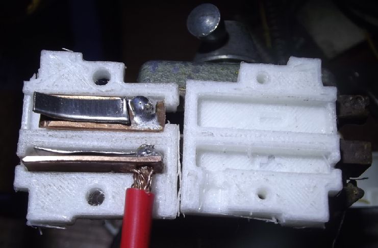 Continuing from June,
near the start
of the month I made another 50 amp T-socket, for a plug-in in the
cabin. I think this is the first illustration where I've shown it
with
the wires. "+" comes out one edge, while "-" comes out one face.
(Here
the "-" wire is being held in a vise helping to keep the pose for
the
picture.)
Continuing from June,
near the start
of the month I made another 50 amp T-socket, for a plug-in in the
cabin. I think this is the first illustration where I've shown it
with
the wires. "+" comes out one edge, while "-" comes out one face.
(Here
the "-" wire is being held in a vise helping to keep the pose for
the
picture.)
With the heavy wire pigtails (AWG #8) the largest,
deepest
"regular face" electrical box is desirable if not vital.
especially when I've added two 20 amp sockets to the same wall
plate
for convenience. (Maybe I should extend the borders of the wall
plate
to make one that can be used with a wholly larger size electrical
box?)
Again, the blades of the socket and the inserted plug
are
pressed together by the spring, to "theoreticly" make
contact all
along one face of each blade. With my design, the spring is a
loose
piece with no electrical connection, held in position by the
assembled
shell. The inspiration for this came from the original T-Plugs,
but
there the springs are external, attached to the plug blades. This
is
easier to make. If I was able to change the original T-Plugs (used
for
20 amp outlets & plugs) to make them more ideal for house
wiring, I
would do them like this and make the blades 10 mm long instead of
8.
Like the "HAT" plugs/sockets I created before I found T-Plugs, and
which are so similar the plugs actually fit into T-sockets. But
without
a manufacturing facility, this is impractical. I did the 50 amp
set
myself because I couldn't find anything suitable available, and
because
it fit with the "T-Plug" philosophy.
Gosh, I ought to 3D print another socket for the
kitchen,
where I put in an inferior draft version where the nylon filament
wasn't extruded hot enough to make the socket solid.
Supercorder Straight Flute Making Instructions

at TurquoiseEnergy.com - URL in image
is gone
From September 2003 and on through 2006, quickly
tapering
off in 2007, I created the Supercorder, a marvelous "21st
century" alto blockflute. Other wind instruments (transverse
flutes,
clarinets, oboes...) had undergone various improvements in the
19th
century and were made louder, but "recorders" were still stuck on
simplistic designs from the 1600-1700's with relatively weak and
uneven
sound, and no way to fine tune while playing. The sound is
beautiful,
but they were inadequate for playing in a modern orchestra,
concert
band or other ensemble.
I modernized the alto recorder, over a century after
most
other woodwinds. I made about 20, of improving characteristics, as
I
went on. I could and did play the new instrument in amateur
orchestras
and concert bands (usually oboe parts, sometimes flute) as well as
in
music jam sessions. The unique sound was often much appreciated.
But of
course I branched off into other endeavors and soon made them no
more.
I still play the one I kept for myself but here on Haida Gwaii
there
are no appropriate ensembles to play it in.
I didn't create it just to let it die there and be
forgotten, but other exciting new things keep taking my attention
away... and now it's been 20 years! I've long meant to "write up
some
instructions" so others could recreate this wonderful instrument
without having to reinvent it. I got earnest about it this month.
I measured up the bore reamers and wrote the exact
dimensions (critical!) for every point along their length, and the
tone
and bolt hole positions from the drilling jig - details vital and
specific to this instrument. Of course, as I worked I started
thinking
of more and more details. Making metal keys and all that
entails...
Jigs, tools and my unique techniques for various things... The
keyhole
surrounds in the wood... How to set key pads on keys... Porcelain
beaks
(with the special shape for the fine tuning hole)... Windway
dimensions
and how-to... How to tune the instrument...
Was I writing something for experienced woodwind
makers,
or did I have to go over a lot of basics - things it took me two
or
three years to learn, even including tutelage from a lady who
repaired
woodwinds? I decided that experienced makers were probably going
to
stick to making the instruments they already knew and were
marketing.
To get a new enthusiast(s) to venture into making "supercorder
straight
flutes", and perhaps make a business or career out of it, I would
have
to bring beginners up to speed on all the relevant topics. If I
can do
that, someday someone somewhere will get the ball rolling again.
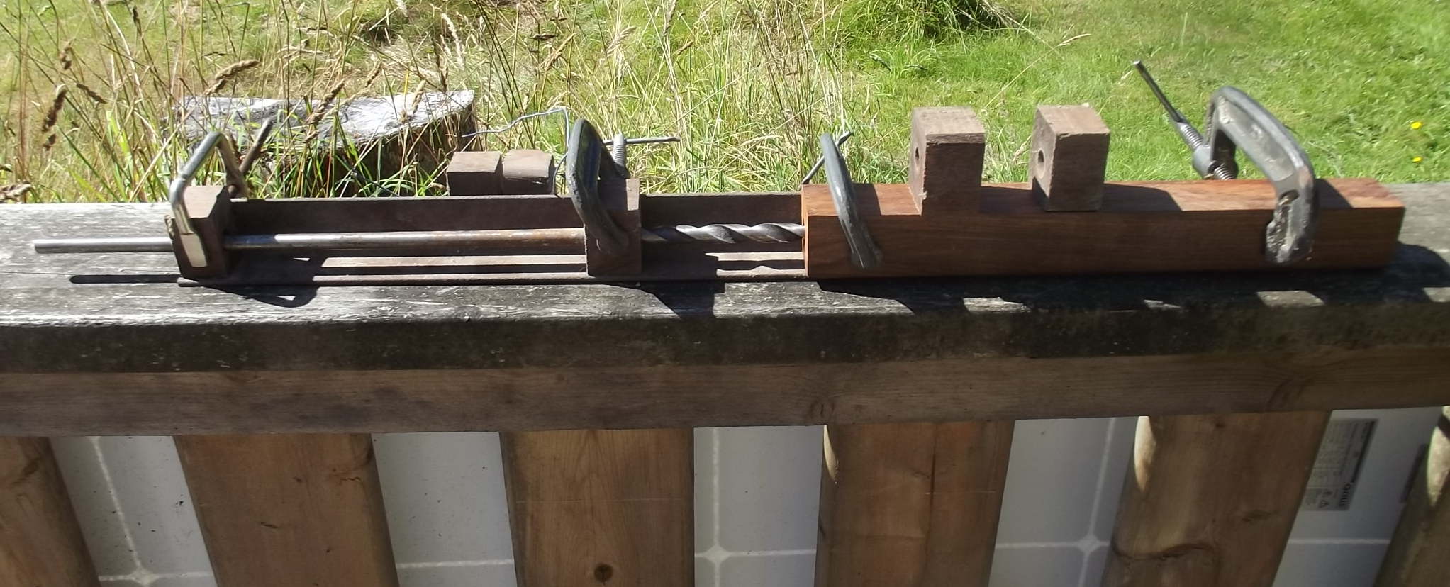
One example of the many
bits of
info
and illustrations someone would need to make this flute:
my angle iron jig for drilling 15 inch long bore holes through
the
instrument body piece and still come out near the center of
the wood at
the far end
Finally I started to realize I wasn't writing a few
simple
pages or a "pamphlet" of instructions but a whole book - even a
considerable tome. There's solid weeks of writing to be done. This
is
inevitably going to take time away from other projects. (No wonder
I've
put it off for 20 years!)
Thinking of new chemie battery Production -- ?
Two chief problems in my experiments were
sufficiently
compacting positive electrode materials, and keeping them
compacted in
the cell. I could solve the first problem for nickel hydroxide
electrodes by using the "+" material from nickel-metal hydride dry
cells. Those cells worked well for a while until the second
problem
raised its head, causing deterioration. (That's why they cram them
into
metal cans!)
When I made cupro-nickel 70:30 sheet metal
electrodes,
they also worked well for a while - really well - but deteriorated
rapidly. But I've had the thought that monel ("nickel-cupro" eg
60:40)
powder might do better, even without compacting it much. All the
insoluble nickel hydroxide would hold the soluble higher-oxide
(valence
+3) copper hydroxides/ions in solid solution? And then there's the
SDBS* to stop dissolved cuprate ions from escaping the electrode,
just
like with the zincate ions. Only 1.2 or volts or so, but it should
make
an everlasting cell with Great energy density. Meanwhile large
lithium
batteries are doing a lot of damage worldwide, even burning
dwellings
and sinking ships. An alternative or replacement is surely needed.
This
is probably worth an experiment or two.
(In the news I saw an older Nissan Leaf like mine that caught fire
at a
fast charger. First time I've heard of a Leaf burning. I think I
won't
ever try fast charging mine!)
* SDBS: sodium dodecylbenzenesulfonate
Puzzling Power Monitor Readings
In the cabin power system two identical DC Power
monitors
read charge and discharge from the battery. The one on the load
side
says "0.0" if nothing is turned on. The one on the charge side
says
"11.2 W" (or so) at night when no solar energy is coming in. This
"zeroing error" adds up to around 8 fictitious "KWH generated"
over a
month.
I decided to swap them. But when I did, it was still
the
one in the charging that wasn't zero, this time the other monitor.
I
tried shorting both sense wires to the same side of the shunt but
it
didn't help - still 11.2 W. To be sure I had actually swapped
them, I
swapped them again. Still whichever one is on the "charge" side
doesn't
zero. even with the solar panels and charge controller breakers
Off.
I'm mystified.
(The monitor in the house system's charging circuit also
reads
not zero: "2.1 W" - not so bad, still a mystery.)
The Mythical New Electric Hubcap Motor
Having some years ago conceived of a better
"unipolar"
axial flux BLDC motor and motor controller plus a few improved
ideas in
the meantime, I finally decided to break the project into three
separate projects, each of which would be a valuable
accomplishment in
itself and not dependent on the next one. The first was to make
the
BLDC motor. I conceived it could be run as a regular BLDC motor
wired
as "delta" instead of "wye" and rewired for unipolar operation
later
with the same coils. Then I could buy and wire up a "regular",
"off the
shelf", BLDC motor controller.
The other two pieces of the "total" project, the
unipolar
motor controller and the "induction powered" brushless
electromagnet
rotor, can be put off until later or even indefinitely.
Then in thinking of the regular BLDC motor
controller, I
then got the idea that by tying one leed of each coil to B+ and
the
other ends to the the three motor controller drive outputs, one
could
get unipolar operation from the bipolar motor controller. Just one
phase of each three would be on at a time, and all would have the
same
polarity. (I thought for a bit one could wire 'north' coils to B+
and
'south' to B- and have a finer torque ripple curve, but then I
realized
that trying to do this with three outputs in place of six would
tie
coil ends together so they would be two in series from B+ to B-
when
the output was unpowered.)
It seemed that there was insufficient reason to make
my
long-planned six phase unipolar motor controller if the job could
be
done - at least adequately - with a commercially made three phase
one.
That eliminates project two entirely. Project three can stay on
the
"wish list" for a long time too if the car runs well with the
original
motor.
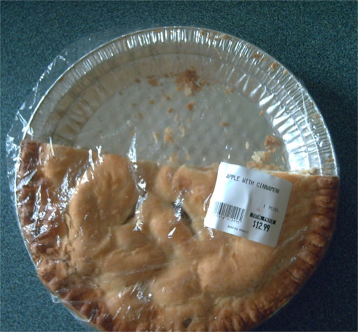
 I (at last) continued
work on the motor by
winding the 12 coils, each 27 winds of #11 wire.
I (at last) continued
work on the motor by
winding the 12 coils, each 27 winds of #11 wire.
Each coil will take the full 36 volts rather than
being
effectively two in series (18 volts each) as in "Y" configuration.
I added the ilmenite [nano powder] to the epoxy. I
don't
know why I never thought of that before, when I was always having
so
much trouble with it flaking off the outside.
It seemed to me the next thing was the plastic plate "end bell" to
hold
the coils. And it seemed I would have to make the plate myself -
from
recycled plastic.
Plastic Recycling 2.0
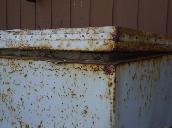
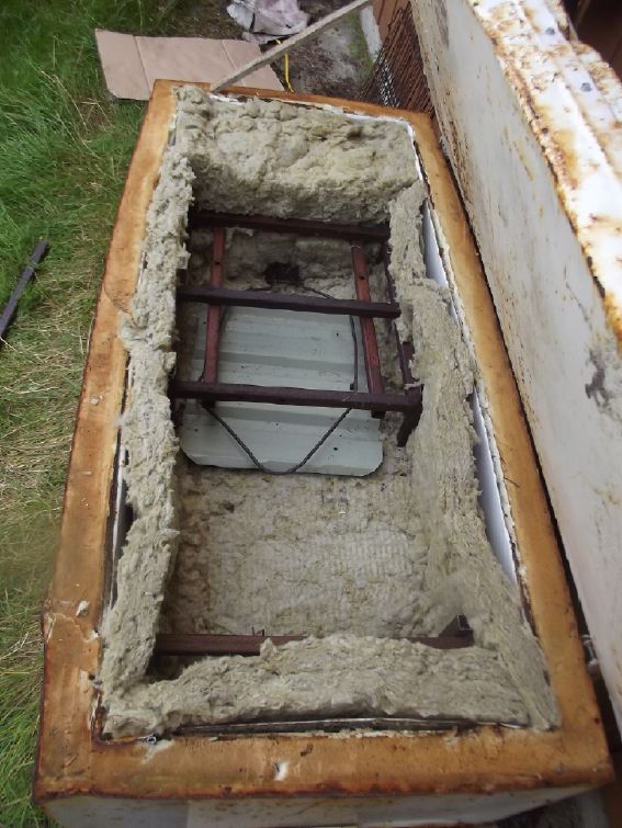
So on the 23rd I finally finished the large oven for
melting plastic, begun so long ago and sitting outdoors under a
metal
roofing sheet. (2022; TE News #164-169,171) I thought I would have
to
remove the ex-freezer's inner 'tub' and replace the melting foam
insulation with something that would take the heat. Then I decided
to
put some mineral wool insulation right inside all around, so that
the
foam insulation wouldn't get too hot. That's what I had done on
the
lid. I bent up the oven element to make it narrower and put a
small
piece of metal roof under it so it wasn't right on the mineral
wool.
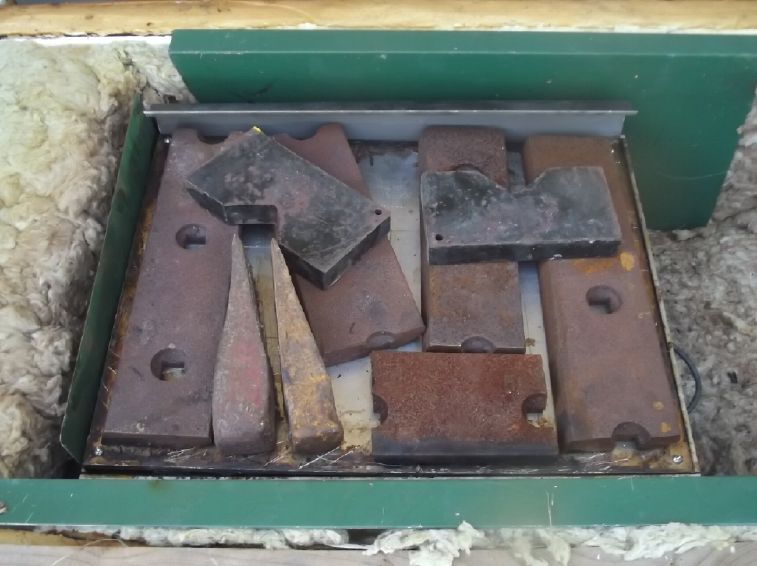
 The lid fit really badly. The mineral wool
sticking up
helped. Then some boards stuck in around the edges.
The lid fit really badly. The mineral wool
sticking up
helped. Then some boards stuck in around the edges.
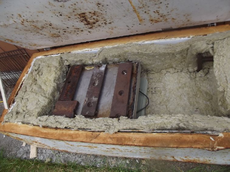
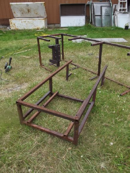 Then I took a metal
frame that I scrounged
for this very purpose in 2022, and cut it up to make supports
inside
the oven. With several tens of pounds of weights on the mold lid,
the
mold needs to be well supported!
Then I took a metal
frame that I scrounged
for this very purpose in 2022, and cut it up to make supports
inside
the oven. With several tens of pounds of weights on the mold lid,
the
mold needs to be well supported!
 Plastic melting oven put off for 3
years,
operational in a day!
Plastic melting oven put off for 3
years,
operational in a day!
 Oven with first mold inside, ready to
melt.
Oven with first mold inside, ready to
melt.
After that I went through a few iterations of trying
to
make a nice plate of polypropylene. I set the oven to 205°C
(400°F). It
seemed to be too hot! The plastic stuck really hard to the mold
plates.
The next one popped off nicely, but the third one stuck fast
again.
Both times it stuck I had to scrape and re-polish the mold plates.
Yuk!
Here is a whole "not very brief" gallery of plastic pictures for
anyone
interested to end "July in Brief".
Otherwise, here we run into August and the Tlell "Fall" Fair.
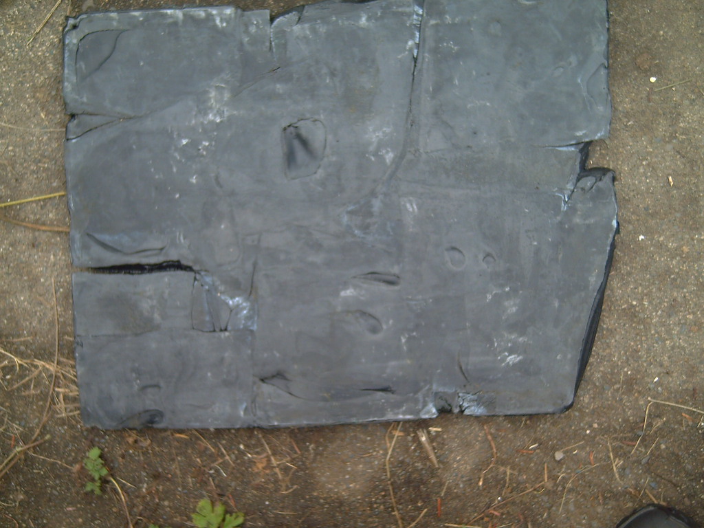
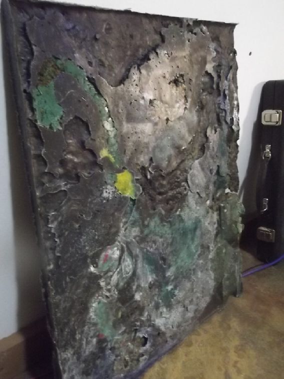 "Contour map" - insufficient
material to fill the
space
"Contour map" - insufficient
material to fill the
space
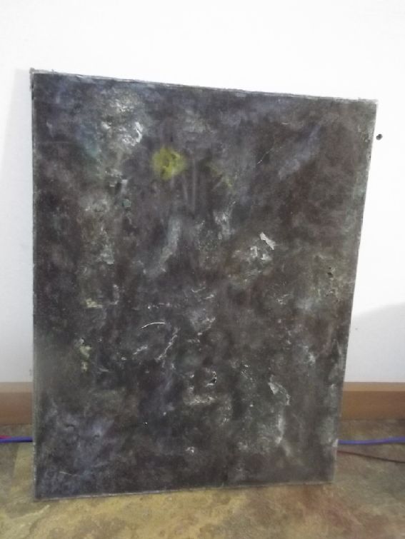
The back side was nicer

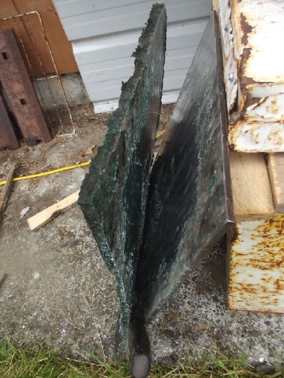
Really glued on! I had to
heat it
up to 75°C
again to get it starting
to come off at all - and even then I had to chisel some of it
off.
Still a mediocre result
Then I decided to try
180°, and oiling the mold plates with canola oil, and a different
plastic: polyethylene from a large fishing float. I cut it up
pretty
small as it was all curved and big pieces stuck up a lot. 3 Kg of
it
fit in the mold better than 1 Kg of ropes.
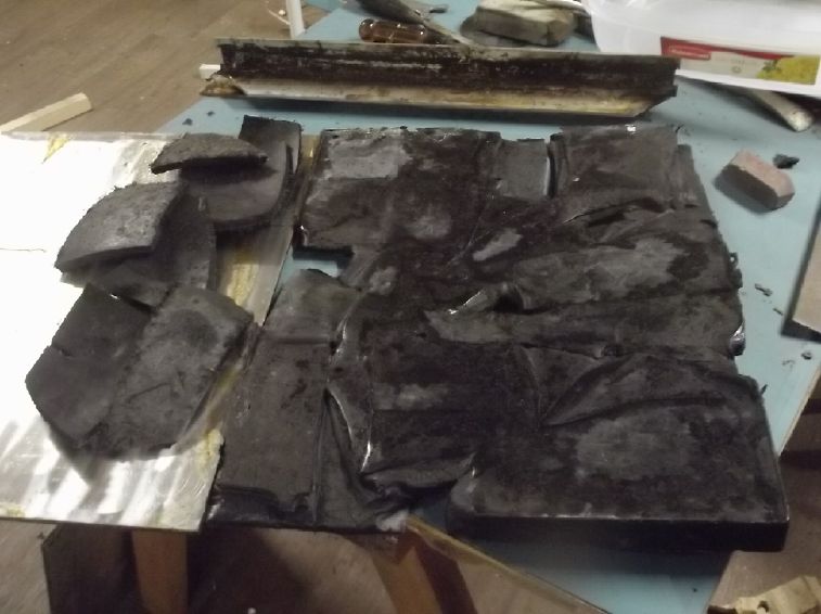 At 180°, plates buttered
with
canola oil, and
with 40 pounds of weight on top, the polyethylene didn't flow
very well.
At 180°, plates buttered
with
canola oil, and
with 40 pounds of weight on top, the polyethylene didn't flow
very well.
It did however pop right out of the mold.
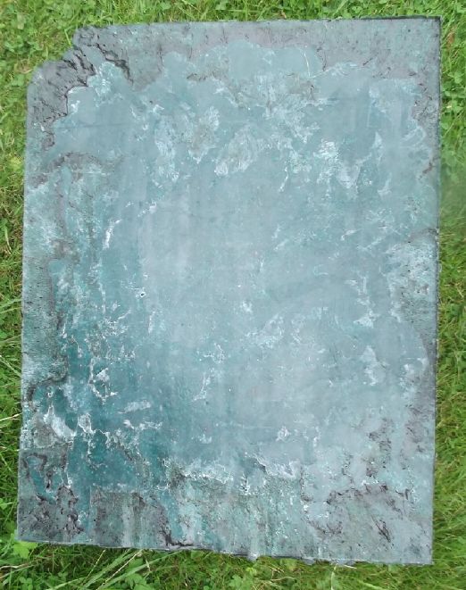
 This time, 80 pounds of
weights
This time, 80 pounds of
weights
It came out better, but still not a solid, square plate.
I think I can get it there. Solid, dense material for the motor
end
plate!
The second try with
more
weight was better but still didn't flow sufficiently. I'll have to
try
a higher temperature - maybe 186°. But I'm going up slowly. I
really
really don't want pieces stuck hard to the mold plates again!
In
Passing
(Miscellaneous topics, editorial comments & opinionated rants)
Electrosmog
in
the
Faraday
Cabin
[15th] I didn't seem to be
getting the sort of tinnitus relief in the cabin that I was
getting a
year ago when I started sleeping there in the summer. This was
especially puzzling when I thought that only the 60 Hz power lines
were
the cause. Now that I understand every frequency through to at
least
UHF (WiFi, cell phones, centimetric and perhaps even millimetric
waves)
contributes, and as I brought computer equipment into the cabin, I
started being affected by new and previously unsuspected sources.
Most especially, I have been feeling like my tinnitus
starts getting worse and worse in the morning while I'm still in
bed.
How could that be? Was I imagining it? After an hour nap in the
afternoon it seemed worse instead of better. I had turned the
laptop
OFF and unplugged the DC to DC power adapter. What on earth else
was
there?
Suddenly it dawned on me that the main solar charge
controller, notwithstanding that it's "MPPT" with a "steady" DC
voltage
output to the batteries, must nevertheless regulate the voltage by
some
form of PWM in the DC to DC conversion. The fluctuating readings
when I
tried to make a "dump load" device that measured the solar panels'
voltage demonstrated that. That would be On-Off voltage switching
at
probably 16 to 100 KHz - supersonic. (15 KHz, maybe even 10 KHz,
is now
supersonic to me.)
It starts charging when it gets light out. In the
summer
that's 5 AM or whatever. By the time I'm getting up it's switching
several hundred watts, charging to make up for the electric heat
I've
been running all night. Likely there's the aggravation. Whether
it's
supersonic audio (actual vibration, humming) or supersonic
electrical
field I don't know, but it explains the timing really well.
Last summer, 2024, the charge controller was
"temporarily"
mounted on the far wall. Then it had been moved to the center of
the
cabin, much closer to the bedroom.
But the charge controller is in a metal housing! I
checked
with a meter. The DC voltage on the housing was jumping all over
the
place. It wasn't grounded. The perfect electrical noise shield
already
surrounding the unit was left unconnected! I connected a ground
wire to
the distribution ground and to one of the controller's mounting
bracket
screws.
I decided I wasn't satisfied with that. I flipped off
the
solar panels' breaker and disconnected the charge controller. I
also
shut off the AC source power supply that I had set to 38 volts in
the
event the batteries became too discharged. (It has never been
needed
since the earliest times of setting up the 36V DC system.) Let's
see if
a couple of mornings without it at all are better, and then try it
with
the shield and see if whether it gets bad again or not. It's
finally
warm enough that no heat is needed at night. The batteries could
probably run lights and computers for weeks.
[Aug 3rd: It's better. I'll be moving it outside entirely, into an
equipment box high up on the far wall!]
[17th] It seems better with the charge controller off. If, as
seems
only too likely, the charge controller hums audibly at whatever
supersonic frequency it switches at, grounding the case won't
help. The
conclusion I reluctantly came to was that it will have to go on
the
outside of the wall in a box. ...the east wall at the north
corner,
where I had it "temporarily" just inside with the batteries, and
where
all the solar panel wiring comes to. ...up by the eaves.
In fact, the little power adapters that power things
like
computers should be outside, too. Yikes! I set my laptop with an
alume
base and an alume pizza tray over it, both grounded, with just the
display sticking out. I can sit a few feet away using a USB hub
and
cables to the mouse and keyboard, and with the text in the editing
window greatly magnified. (I bought another display, but I've been
unable to get the computer to output to the HDMI video port. I
also run
the laptop off its battery while I'm there, and turn it OFF when
I'm
not using it but in the room. When I go to leave I shut it down
(or
"sleep" and plug in the DC to DC power adapter to recharge it.
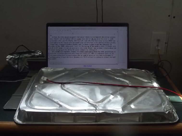
Laptop sitting on metal
plate,
covered by
baking tin except display.
It's all grounded.
It's a diabolical machine. There's no worse
electrosmog
than the intentionally broadcast WiFi, and it turns it back ON
unbidden
whenever the computer powers on, with no indication that it is on,
not
even a tiny icon! Unless I remember to turn it off (after it has
finally booted up, told me to enter my password then showered me
with
distractions bringing up menu bar, icons and windows), or until it
dawns on me that my tinnitus is getting worse, it just sits there
blasting me. WHY is there no setting to default the WiFi to OFF?!?
I bought a VGA to HDMI adapter and got the new
display
working from the old laptop. The larger display makes it
good
enough for writing with.
Here's a taste of some of the "electrosmog" stuff at researcher
Magda
Havas' website (MagdaHavas.com) on electrosmog. If I'm noticing
tinnitus and it's only the least hidden of many effects from EMF
fields
and radiation, the whole area is potentially of more than academic
interest to a lot of people. Someone I talked to thinks a lot of
people
(in Victoria BC) are going around in a "brain fog" since they put
in
all the "5G" cellphone towers, and he says his car radio
completely
breaks up into static when he passes by places where they are
known to
be.
<<
 This "allowable exposure standards"
table shows the
nonchalant treatment of the whole subject area by the West
compared to
what researchers who were probably more biased toward "playing it
safe"
came up with. Havas says the American standards were based only on
occasional exposure by telecomm workers, not for men, women and
children to be subjected to them "24-7" at home, work, school and
everywhere - even by multiple sources and frequencies at once.
This "allowable exposure standards"
table shows the
nonchalant treatment of the whole subject area by the West
compared to
what researchers who were probably more biased toward "playing it
safe"
came up with. Havas says the American standards were based only on
occasional exposure by telecomm workers, not for men, women and
children to be subjected to them "24-7" at home, work, school and
everywhere - even by multiple sources and frequencies at once.
The table is from: Influence of High-frequency Electromagnetic
Radiation at Non-thermal Intensities on the Human Body
(2001) - A
review of work by Russian and Ukrainian researchers)
No Place To Hide – Newsletter of the Cellular Phone Taskforce
Inc.,
Volume 3, Number 1 – Supplement, 33 pp.
1. Introduction
2. Natural Electromagnetic Background
3. History of Research in the USSR
4. Physical Approach to Resonant Absorption of Low intensity HF
EMR
5. Reception of EHF EMR at the Cellular Level
6. Experiments on Animals
7. HF EMR in Medicine
8. Mechanisms of Action of EHF EMR on Biological Objects
9. Standards and Normalization of HF EMR
10. Effects of High-frequency Communications Media on Human Health
11. Discussion
12. Conclusions
13. Appendix
14. References
>>
Ultrasonic Smog
[28th] A month or so ago I had discovered that DC to DC power
adapters
evidently 'humming' at maybe 50-100 KHz were a big tinnitus
problem,
and probably from actual ultrasonic sound waves rather than from
their
electric field. (AC power adapters are probably little better
except
for generally being lower power capacity and housed in a sealed
plastic
case blocking much of the sound.) I had moved it to the floor
downstairs and made a long cord to bring the power upstairs to my
old
19 volt laptop. [It's slower, quieter and WiFi & networking
can be
turned OFF until manually turned ON again.]
One morning I thought, after it being On a while,
that it
was still aggravating my ears even from 10(?) feet away through
the gap
under the door - and maybe through the floor and wall too!
I took one very long cord and made a second one, and
threw
the converter outside the far door of the cabin. Surely that will
afford relief! At least until it rains, the unit shorts out, and
my
laptop blows up. Hmm. I put a bucket over top of it. (As if on cue
-
drizzle!)
If I wasn't sitting in a "Faraday Cabin" with very
low
electrical noise, in the morning after my tinnitus having been
somewhat
quieted down from sleeping there overnight with everything
(especially
including the adapter) unplugged or off, I probably wouldn't have
noticed. It would have been just one more unsuspected ear/tinnitus
aggravation of many, an innocent looking little box.
The solar charge controller also seems to be a source
of
ultrasonic smog. I've found an large electrical box and plan to
move it
outside on an outside wall far from where I usually am - the side
where
the power lines are anyway. In fact, probably up by the eves well
above
where people are (outside or in). In the meantime, if I'm in the
cabin
it's turned off.
I tried online to find some meter to measure
ultrasonic
audio, or all audio up to (at least) 100 KHz, but I drew a blank.
Most
audio level meters it seems crap out somewhere below 10 KHz.
Scattered
Thots

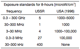
* This seems exaggerated. I once heard that sometime in the 1950's
10$
would buy a week's groceries -- probably that was for a family. I
remember bread at about 25 cents a loaf around 1967. In the early
to
mid 1970's 20$ might have got a full cart.
But if the time scale is off, it's still
illustrative! In
July 2025 I just paid 37.59 $ for one nice big carrot cake. (I was
in
shock when the price came up on the cash register. I almost put it
back.)
* The "private central banks" system makes currency into a pyramid
scheme. Money from thin air is "loaned" to the government. The
government
then "owes" the money back with interest. The money to pay
the
interest
can only, in the final analysis, come from borrowing more money.
Governments will spend what they will. Wherever the
money
comes from, it is incumbent on them to be prudent and spend wisely
on
the public's behalf. Wouldn't it be better to have the public
treasury
simply print the needed money itself? Then nations wouldn't be "in
debt". The money wouldn't be "owed back" to make bankers rich, men
who
have done little of productive value to create the wealth they
assume
possession of. The end of government interest payments alone would
cause a lowering of taxes. Of course, greedy bankers have always
found
some misinformed person with a grudge to murder national leaders
who
try to eliminate private central banks. Andrew Jackson was the
only one
on whom the guns misfired, and the US was rid of private central
banks
for 80 years until Christmas 1913.
Reckless, unproductive spending (by governments...
and
citizens themselves) and private banks able to conjure money into
existence (central and otherwise) have both contributed to
impoverishing the citizens of nations round the world.
* The Nazis conquered Germany by force before they went on to
attack
other nations. At the Nuremberg trials someone asked Hermann
Goering
something like "Weren't there people in Germany who objected to
this?"
Goering's chilling reply: "Not above ground."
I had an uncle (my mother's sister's husband) who was
in
the Canadian military. Shortly before he died, he confessed to his
family that in World War Two he had been an assassin for the
Canadian
government, killing people the government didn't want around.
It was wartime, but is the parallel not disturbing?
ESD
(Eccentric Silliness Department)
* The schizophrenic went on a relaxing vacation hoping to find
some
peaces of mind.
* Pi = 3.14159 ; 1/2 Pi = 6.495
"in depth
reports"
for each project are below. I hope they may be useful to anyone
who
wants to get into a similar project, to glean ideas for how
something
might be done, as well as things that might have been tried, or
just
thought of and not tried... and even of how not to do something -
why
it didn't work or proved impractical. Sometimes they set out
inventive
thoughts almost as they occur - and are the actual organization
and
elaboration in writing of those thoughts. They are thus partly a
diary
and are not extensively proof-read for literary perfection,
consistency, completeness and elimination of duplications before
publication. I hope they may add to the body of wisdom for other
researchers and developers to help them find more productive paths
and
avoid potential pitfalls and dead ends.
Electric Transport
Making the Mythical New Electric Hubcap Motor
Breaking Daunting Project Into
Three
Smaller Ones
[18th] I couldn't seem to get on with this motor plan - for years
now.
Now I think to break it down into three separate projects, each of
which would be "complete" in itself without doing the next one(s):
1. A 12 coil, 8 permanent magnet poles "Electric Hubcap" type
motor
along the lines of my previous versions with improvements I've
thought
of over the years including for more robust construction and
mixing the
ilmenite into the epoxy for the coils.
I've recently realized that it can be the same
motor
for either bipolar or unipolar operation. I was already going to
make
it so the coil wire ends poke out and are connected externally, so
it
can be easily reconfigured. If I wire it up "Delta" instead of
"Wye",
then the coils will have the same voltage and so the same number
of
windings for either bipolar or unipolar operation. At 36 volts
that's
about 27 or 28 windings instead of the 20 or 21 of my previous "Y"
wired motors. 27 winds of #11 wire is exactly three full layers of
wire.
I will also just complete the Hallbach configured
permanent "supermagnet" rotor that I started making some months
back.
Forget the improved but more complex rotor with electromagnet
poles to
be powered via induction instead of troublesome brushes & slip
rings.
That means I can build Just the motor similar to the
way
I've built them before (with all the latest of course), and simply
buy
a BLDC motor controller instead of having to make the unipolar one
before I can make it run. Curtis, known for reliable motor
controllers,
seems to make several variants, a couple of which should work fine
and
hopefully still use the old Curtis handheld programmer that I
already
have.
[Aug. 3rd - Hmmpf: On line I've contacted 3 Canadian Curtis
distributors and none have bothered to reply.]
2. Once the car is on the road via "1.", and if I then decide I
have
time to spend on it, I can build the unipolar motor controller. I
suppose unipolar isn't a vast improvement in reliability given
that I
finally decided it would actually have to have both high and low
side
mosfets for best efficiency (the high sides being used only for
synchronous rectification). So "shoot through" currents are still
possible. (What are the chances of any controller I make even
being As
reliable as a commercially made motor controller of a quality
brand?)
Still I think it should have the efficiency "edge" by
not
reversing the magnetic polarity of the iron particles in the coils
and
so it avoids that bit of hysteresis inefficiency and heat.
[Unipolar
motor controller ideas are scattered in various issues of TE News
from
2016 on, where I made and used one on the "ARM", a feeble attempt
at an
"Axial flux Reluctance Motor". It got unexpectedly hot largely
owing to
use of simple diodes instead of synchronous rectification.]
3. Finally if I still want to I can delve into the further
intricacy of
making a new electromagnetic coils rotor, with the new "induction"
technique for powering the rotor coils (rather than slip rings).
[An
appropriate configuration with a "U" shaped inductor primary and
two
rings on the rotor to match was shown some TE News issues back.] I
could change the rotor without significantly changing the rest of
the
motor. This rotor would be able to turn down its magnetism as RPM
increases. This would give the motor more torque (and hence power)
when
running at higher RPM's, ie with the car at highway speeds. This
will
or would mean adding complexity and induction transfer components
as
well as the coils rotor itself.
Time moves on and I'll probably be happy just to
FINALLY
make the motor, put the Sprint car on the road to demo a great
"ultra
efficient" axial flux BLDC motor, and leave the (formerly
futuristic)
refinements to someone else.
I started getting out stuff to make coils. It took me
a
while to locate my ilmenite, which don't think I've used since I
moved
from Victoria. (It was near my other "pottery" chemicals, but in
another box hidden under some clutter.)
[19th] I set up the coil winder, having somehow managed to keep
all its
parts together, and got everything ready. Then I mixed 10 grams of
ilmenite, 10 grams of epoxy 'hardener' and 50 grams of epoxy resin
("West System" epoxy) to make just 70 grams of ilmenite infused
epoxy.
After mixing it I poured 1/3 of it into one little plastic cup and
kept
2/3 in the other. I put the 2/3 in a freezer so it wouldn't set
(for a
couple of days, anyway).
 I wound the first two
coils, painting
illmenited epoxy onto the iron powder core before the first layer
and
then onto each new layer of windings. When each coil was wound I
used a
cable tie to prevent it from unwinding. But I also remembered a
trick
of pulling the wire across the winding handle so it wouldn't
unwrap if
I had to pause and let go during the winding.
I wound the first two
coils, painting
illmenited epoxy onto the iron powder core before the first layer
and
then onto each new layer of windings. When each coil was wound I
used a
cable tie to prevent it from unwinding. But I also remembered a
trick
of pulling the wire across the winding handle so it wouldn't
unwrap if
I had to pause and let go during the winding.
It was still tacky at bedtime. I can't put the coils
in
the oven to cure them faster the way I used to in Victoria because
this
cursed oven has no "warm" setting below "much too hot", at no
particular stated temperature. (That makes it no good for raising
bread
dough in, either.)
[20th] I gave the coils (now set) another coat of ilmenite/epoxy
from
the cup in the freezer and set them in the sun in the morning,
then
wound two more in the afternoon. The direct sunlight got the epoxy
to
set pretty rapidly. When they were ready I gave them their outer
coat.
In the evening I wound a 5th coil, but had to stop there as the
mix was
nearly gone and I didn't want to mix another batch so late.
I wonder that I never thought in past times, with all
the
troubles I had getting the ilemnite not to flake off, to mix it
into
the epoxy. I guess I was thinking that it was just supposed to be
on
the outside where the epoxy was inside the windings. Even then it
would
have been easy to mix it with epoxy and paint it on the outside.
(And
why shouldn't it go within the winds as well as around
them?
Probably better! In fact, why wouldn't one want magnet wire makers
to
add ilmenite to the insulation? Probably even better!)
[22nd] I finished winding the coils, giving them a second coat of
ilmenited epoxy, then (when set) filing off excess epoxy and
touching
them up.
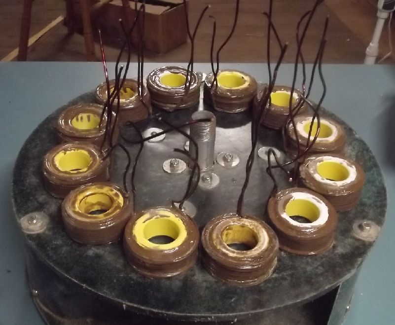
Council of Motor Coils in
session. All those FOR
making a motor raise your tentacles!
Unipolar Motor Controllers Are Commercially Available!?!?!
(Then, this boy is DONE with making motor controllers!)
I started thinking about motor controllers again. The
original reason for wanting a unipolar motor controller was so
that it
could use low-side mosfets only, eliminating the possibility of a
short
circuit from having top and bottom transistors both transiently
come on
at once. That would probably drasticly improve the reliability of
my
home-made motor controllers. Then too, it was to eliminate the
iron
hysteresis losses associated with repeatedly reversing the
magnetic
polarity. (Of course, with the ilmenited iron powder coil cores,
those
losses are already much reduced over typical motors.)
But if one is to have high-side mosfets anyway for
synchronous rectification, where is the reliability gain? And if
commercial car motor controller makers are making them essentially
100%
reliable now, it's the law of already diminished returns. The
Kelly
controller worked great in the car until two phases of the motor
shorted. (Which said I should change the motor wiring techniques,
not
the controller.)
Then I started thinking about wiring the motor in
Delta
instead of Y. Delta is fine for sine wave AC... but if A and B are
on,
aren't the two legs going between A and B through C "half on",
backwards? Is Delta even a legit configuration for a BLDC motor?
Would
"C" have to be switched high or low instead of the usual choice of
leaving it unpowered?
But one could gain a three-phase unipolar operation
by
tying one side of each coil to "B+" instead of going either Delta
or Y.
Then it would get the full battery voltage when the coil's other
wire
is driven low.
Furthermore, the magnetic polarity of the
coil can
be set as desired by reversing the ends of the wire regardless of
the
electrical polarity.
Furthermore [wait... this doesn't work! But read
on.],
that's only using the low side drivers and getting three phases.
One
could tie the other half of the coils to ground instead of B+.
Then
they would be driven ON by the high side mosfets, at the
phase
angles right between the low side driven coils. Again, the unpolar
magnetic
polarity is independent of the electrical polarity.
Thus it seems we can make a six-phase unipolar motor
controller out of a three-phase bipolar controller. It's all in
the
configuration. Well, DUH! Here I finally have a simple answer to
something that looked really complicated. ...like adding the
ilmenite
to the epoxy and other great simplifications occasionally and
finally
found for vexing problems.
From this moment I'm going to drop any and all ideas
about
making my own motor controllers. I haven't been very successful at
it
in past efforts, and if I can't improve on an available commercial
product, there's little point to it.
[23rd] Oops: Wired in delta, if each output of three is taking one
coil
low and one high, the two coils are going to be in series from B+
to
ground when the output isn't driven. It can be made to work but by
only
using the low side drivers, so no coil is ever driven "south",
only
"north", in a three phase manner. More torque ripple, but it's
simpler.
Moving on... The next task is the housing. Metal is out for
electromagnetic reasons. I want to make it of polypropylene, but I
was
unable to buy a sheet of it a while back. The obvious thing would
be to
make it out of old PP ropes washed up on the beach. That meant
getting
back to the plastic recycling project I had started 2? 3? 4? years
ago.
So that occupied the next days.
Oven, not
pretty but ready in a day! added rock wool
insulation,
bent-up oven element (on gray metal), shelving for
molds
[23rd and on] I
finished
up the large size plastic oven I started making from a discarded
freezer about 3 years ago. It went faster and more easily than I
expected. Then I scraped and polished the mold plates, still with
baked
on crud from its last use so long ago. Finally in three bakings in
the
now temperature controlled oven, I cast a thicker plate of PP than
any
before. But there were still a lot of air bubbles causing voids
under
the top mold plate. By early August things were looking more
promising.
I cover this in more detail under Plastic
Recycling
Of course, that was it for progress on the motor
itself.
[August 7th] Last night it occurred to me that while the low side
drivers of one phase of my own KBL36301 Kelly controller were
burned
out, I could use just the high side drivers for unipolar
operation.
What? I don't even need to buy a motor controller? What about the
synchronous rectification at turn-off? Or does that go through the
other two phases? Did I damage the board too much for the rest of
the
controller to work when I was futilely trying to repair it?
Okay, it might, or might not, work.
Other "Green" & Electric Equipment Projects
Solar Deep Well Pump
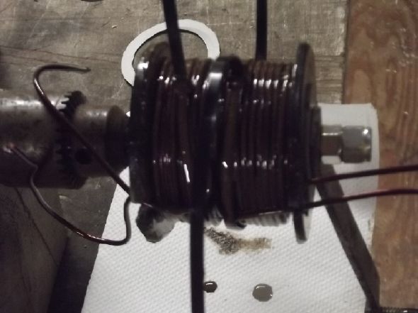
 [15th] 3 or 4 years ago I
bought a "solar deep well pump": "24 volts, 300 watts". It had a
solid
state control box with BLDC motor controller and that type of very
efficient motor. According to the web page info, it sounded good
enough
for my 67 foot deep well. Now my 36 volt DC systems are running
great
and could surely supply the well pump even in winter, since it
usually
doesn't run very long. On top of everything else, if the well pump
was
DC, I could turn off the 240V AC going under my bedroom to the
shop at
night and eliminate it's strong electric field.
(Electrosmog/Tinnitus
reduction)
[15th] 3 or 4 years ago I
bought a "solar deep well pump": "24 volts, 300 watts". It had a
solid
state control box with BLDC motor controller and that type of very
efficient motor. According to the web page info, it sounded good
enough
for my 67 foot deep well. Now my 36 volt DC systems are running
great
and could surely supply the well pump even in winter, since it
usually
doesn't run very long. On top of everything else, if the well pump
was
DC, I could turn off the 240V AC going under my bedroom to the
shop at
night and eliminate it's strong electric field.
(Electrosmog/Tinnitus
reduction)
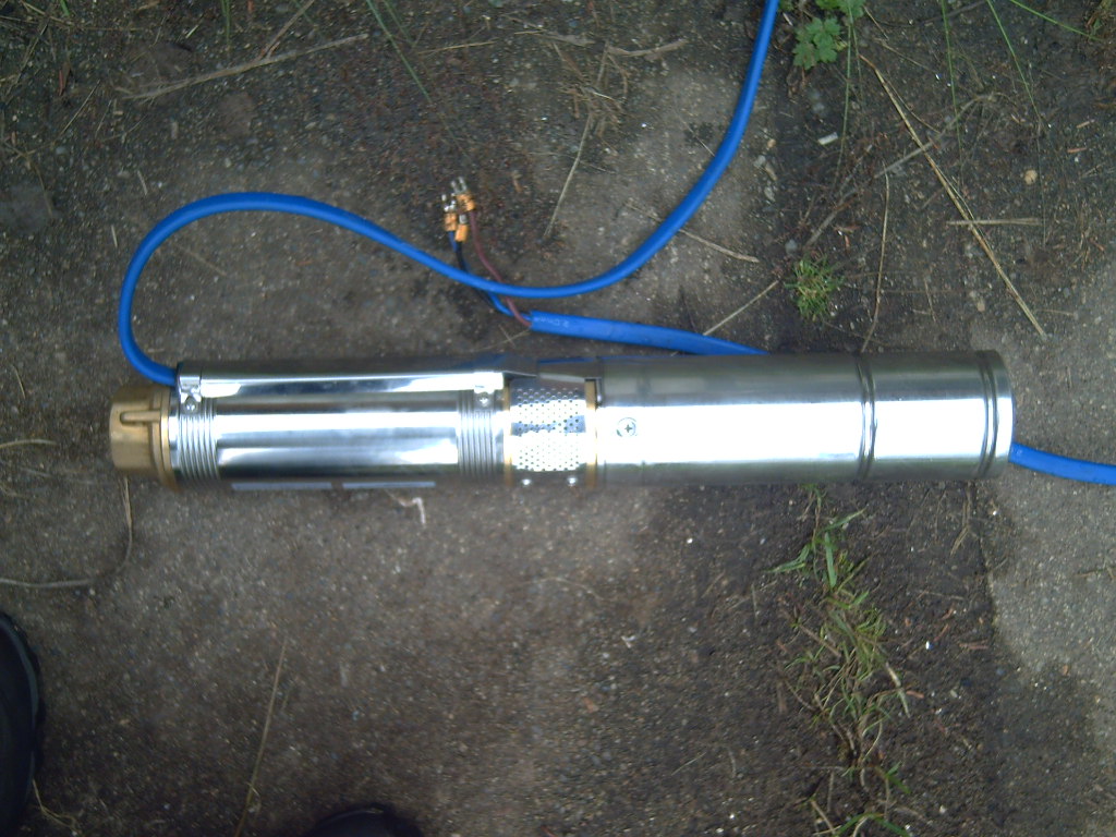
A while back I also bought two 25 amp DC to DC
converters
to reduce the 36 volts supply to 24 for the pump. I finally got
the
pump out of storage and read the instructions. Great zot! It would
run
on 36 volts! As a bona fide solar pump, it would run on pretty
much
whatever solar panels would put out, up to 48 volts abs. max.
That's
simpler, with no DC to DC needed. Too bad I didn't read the
booklet
earlier. In fact, the supply voltage specs were identical to those
for
the 36 volt pump... which the web page hadn't offered me. There
the
choice was 24 volts or 48. Hmpf!
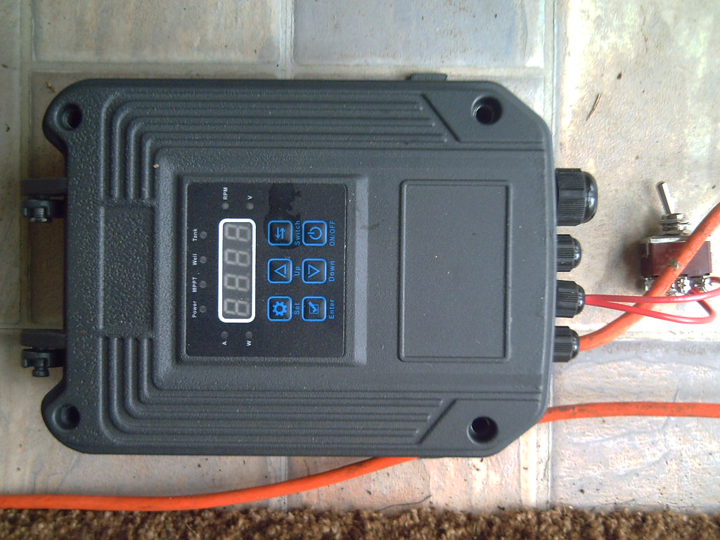 Pump Controller
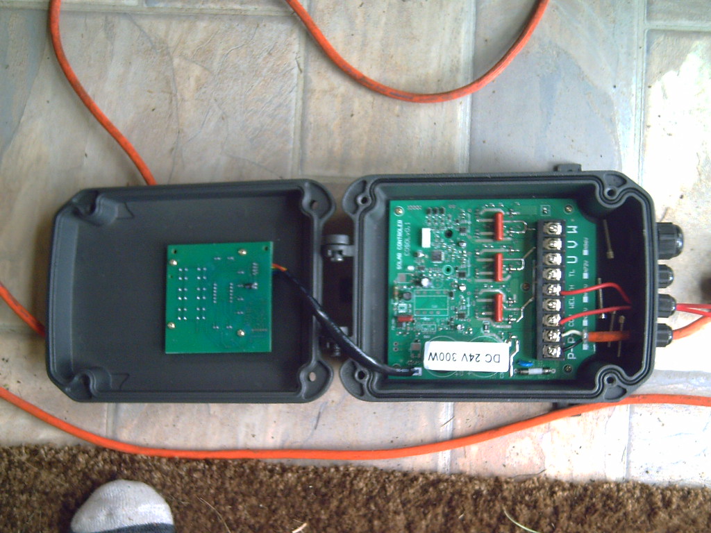
Pump Controller Opened
I connected the pump wires to the controller and made
a
long #16 AWG cord with a 36V plug on the end. I took it outside to
a
rainwater barrel. Then I thought to put in a switch so I could
turn it
on right at the pump, and quickly off again if needed, instead of
it
coming on as soon as I plugged it in in the kitchen without me
seeing
it start up.
I plugged it in and went out and flipped the switch.
Water
gushed out of the pump. It didn't seem very strong and didn't
spray out
of the barrel, but it sprayed and I couldn't slow it down trying
to put
my hand over the outlet. The pump was running at 3400 RPM and
drawing
310, 334 or 350 watts depending which meter you believed. A bit
under 9
amps at 35 volts. (The actual battery voltage was still over 40 -
too
long of too thin wires!) The voltage will be higher when installed
and
plugged in nearby the power box in the garage. The power to the
actual
motor deep in the deep well will however go through around 130
feet of
wire. (AWG #12)
I wired my test switch from "COM" to "TH" - "tank
high".
In this case, it'll be "tank up to pressure". When I flipped the
switch
On the pump stopped. It didn't seem to resume when I turned it
off.
Perhaps it has a time delay. I wasn't into waiting around for what
might be 30 minutes.
[17th] I picked (after rinsing, de-stemming and cutting off
occasional
bad bits) 300 grams of strawberries, adding to the 100 I picked
from
the earliest crop. I ate a few and froze the rest in a ziplock
bag. I
should have picked a larger bag - it's already full.
Then suddenly no more. They're "everbearing" through
summer but with the crappy weather there seems to be a pause after
the
first crop. Now there's lots of runners going every direction.
What to expect from a 4 by 5 foot berry plot?
Outdoor Fruit & Nut Trees
Originally I had a circle of fence wire (of some
sort)
around each fruit tree. Then I planted a "pollinator" pear inside
with
an apple tree. Sometime I ended up with the walnut and an apple
together. This was murder to maintain. Grass, weeds, ferns and
even
woody plants would grow inside the fence circles and through the
wires,
making them hard even to remove to get in.
This month I ripped out most of these. I cut some
stakes/posts and did one large fence around all except the
farthest
pear over.
I came back and found the chickens inside. Great,
they
could root out some weeds and bugs! But I wondered how they had
got in.
Crawled under somewhere? I opened the "gate" - just a piece
between two
posts that hooked on one end - for them to get out easily. An
opportunist missed no opportunity. I came back about three hours
later
and found that a deer had gone in and eaten all the leaves up to
about
a meter+ on all the trees except the walnut, which had no leaves.
Why
waste time with individual trees each in their own little fence
circle
when you can go in and eat five trees at once? It ate half the
little
green apples, and the leaves on my apple graft - the one and only
successful graft I've ever made in my life out of innumerable
tries
over the years. (I was sorry I had pruned away the branches around
it
to give it lots of room to grow.)
On the plus side, it looks like there were enough
leaf
bits left on my graft that it has survived. It's budding a new
leaf.
I've used branches with flowers from this particular tree to
pollinate
my own trees before and I'm expecting much better pollination when
this
branch starts producing its flowers.
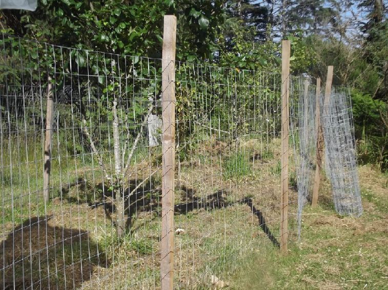
From a circle of wire
around each
tree,
It turned out the chickens were (are) getting in behind the
remainder of the spool of wire, which I hadn't cut off and
stapled yet.
There are just a few apples on each of the large
trees,
"liberty" and "empire". The "pollinator" "northern spy" produced
on
flowers this spring. I don't think much of the "empire" apples.
And
they don't keep long. The "liberty" are nicer, but neither one
gets
very big. I think the trees are too near the ocean, with
southeasters
blowing right up the driveway towards the fruit trees.
This year is slightly exciting because one of the
pear
trees set fruit and is growing just three little pears, all in one
clump. In eight years neither tree has had any pears. (Two years
ago
they set a few but some squirrel came along and nipped them all
off
almost before they started growing - Grrr!) Three pears is nothing
but
at least I get to see what "Clapps Favorite" pears look like.
(Longer
and thinner than bartlett, already reddish.)
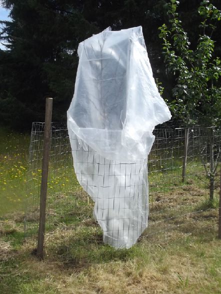 Walnuts On the 7th(?) I noticed tiny
buds on
the bark of my seemingly dead large walnut. It was such a cold
spring
that the buds that came out in May died on both trees. And it was
still
cold. I decided to put plastic bags over both to try and at least
keep
the wind off them. On about the 15th it finally warmed up but it
was
quite breezy. The wind carried off both bags. I tried to do a
better
job of anchoring them, using bungee cords around the trunk of the
large
tree.
Walnuts On the 7th(?) I noticed tiny
buds on
the bark of my seemingly dead large walnut. It was such a cold
spring
that the buds that came out in May died on both trees. And it was
still
cold. I decided to put plastic bags over both to try and at least
keep
the wind off them. On about the 15th it finally warmed up but it
was
quite breezy. The wind carried off both bags. I tried to do a
better
job of anchoring them, using bungee cords around the trunk of the
large
tree.
I've been watering them daily in the hopes they would
spring back to life. I wasn't really expecting anything until I
saw the
buds. I hope the small black walnut will commence too. My place is
just
too close to the ocean and the place I've planted them gets the
breeze
off the beach. (You'd think with 2 cleared acres I could find some
better spot for my fruit and nut trees. I haven't.) Combine that
with
an unseasonably cold, cloudy spring and early summer... Walnuts in
Port
Clements away from the open ocean seem to be doing fine.
[August 4th] Wow... Just a couple of leaves barely starting to
open on
the big tree and what might be the beginning of buds on the small
one,
and the weather has turned cold and miserable again! [August 7th]
A
couple more now, and leaves are starting to open in three clumps.
Might
be some tiny buds on the little black walnut too. (or it's
starting to
grow lichens.)
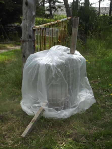 The cover on the small
walnut.
The cover on the small
walnut.
Yes that's the beach and ocean just across
the highway and past a row of spruce trees.
Greenhouse
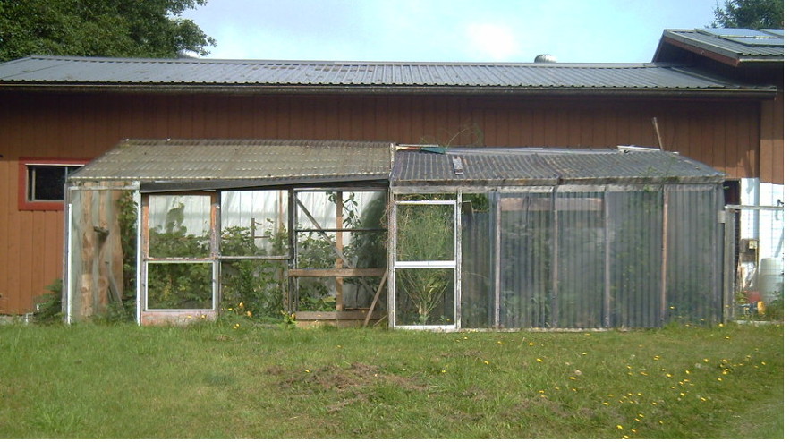
Greenhouse (Aug 7th) It
kind of
grew
in pieces, neither half being the original.
I've just finished replacing plastic that let little light
through with
scrapped window glass
on the big door at the right hand side of the left half.
(There's a 2 by 4 behind the door because the roof support
board chose
right in the middle
of the door, the widest span, to have a big knot that let it
sag down
to hit the door.)
Squashes want to grow out under the door and grow onto the
lawn.
I got some lovely big orange squashes on the lawn that way 2
or 3 years
ago so I'm encouraging it.
Many things grow better in a greenhouse this far
north, or
outside the south wall of the house. Here the winter is often
about as
mild as Victoria about 5 degrees farther south. It contrasts with
Edmonton at the same latitude where it is often way below freezing
for
the whole winter. Instead the summer is usually quite cool and
many
common crops struggle. I've said before it's almost a unique
climate.
In addition I'm very close to the shore - Hecate Strait. Other
gardeners do better a bit farther from the sea.
The Apricots, just before I
picked
them on the 30th

The avocado pit from the compost pile that I planted
in the house last fall is growing leaps and bounds.
...What do I do with it?

South side of West end of greenhouse.
The Strawberry Tree (Arbutus Unido) I got this spring is also
growing
leaps and bounds,
tho presently hard to see in the tomatos. (Its main stem is just
right
of the
closest tall stake.) These are delicious, juicy fruits.
I should get a lot of tomatos.
Note the yellow edges of the zucchini leaves (front). Potassium
deficiency.
I've sprinkled some woodstove ashes under it.
.
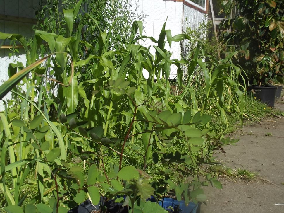
With the sudden heat from mid July the corn suddenly
started taking off, along with other things that hadn't been
growing
very well.
Outside Gardens
 Josta berries are apparently a cross between
currents and
gooseberries. They are similar in size to gooseberries rather than
the
small size of currents, and the bushes aren't full of thorns like
gooseberries. Mine are black but I've seen red ones too. I might
call
them "grape size black currents." Less seedy.
Josta berries are apparently a cross between
currents and
gooseberries. They are similar in size to gooseberries rather than
the
small size of currents, and the bushes aren't full of thorns like
gooseberries. Mine are black but I've seen red ones too. I might
call
them "grape size black currents." Less seedy.
Somebody gave me two plants about five years ago. I
planted them on the west end of the garden on the south side. They
had
nothing until last year, when there were a few. This year I picked
a
cup or more off one bush and made a "josta upside down cake" type
dish.
Mmm.
 At
the
opposite
corner
the
new
yamhill
hazelnut
doesn't seem to be
doing too well. I think of various things it could be, but I'm
probably
not watering it enough. (It's rather "out of sight" and too many
other
things to remember!)
At
the
opposite
corner
the
new
yamhill
hazelnut
doesn't seem to be
doing too well. I think of various things it could be, but I'm
probably
not watering it enough. (It's rather "out of sight" and too many
other
things to remember!)
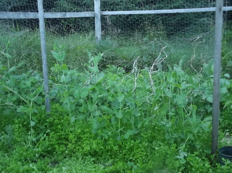
Peas mid month
...and chickweed. Oodles of chickweed.
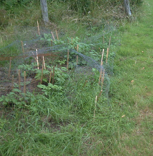
I revived a bit of this little patch with the rototiller and
some
sprouting
"Russian Blue" or "Violet Queen" potatos with purple skin and
flesh,
and a few
prolific "Huckleberry Gold" with yellow flesh, all left over
from last
year.
Potato tops are poisonous.
That doesn't stop the deer from eating the tender tops.
I suddenly got the inspiration to simply throw pieces of
chicken wire
over
the top of the whole patch. It's spotty coverage but it seems
to be
working
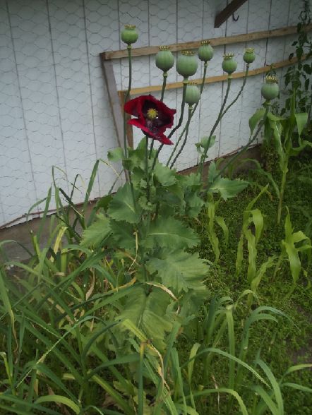
A large volunteer poppy in the garlic patch.
Should be a lot of poppy seeds in those globes!
(I'd better harvest them all or poppies may be my new worst
weed!)
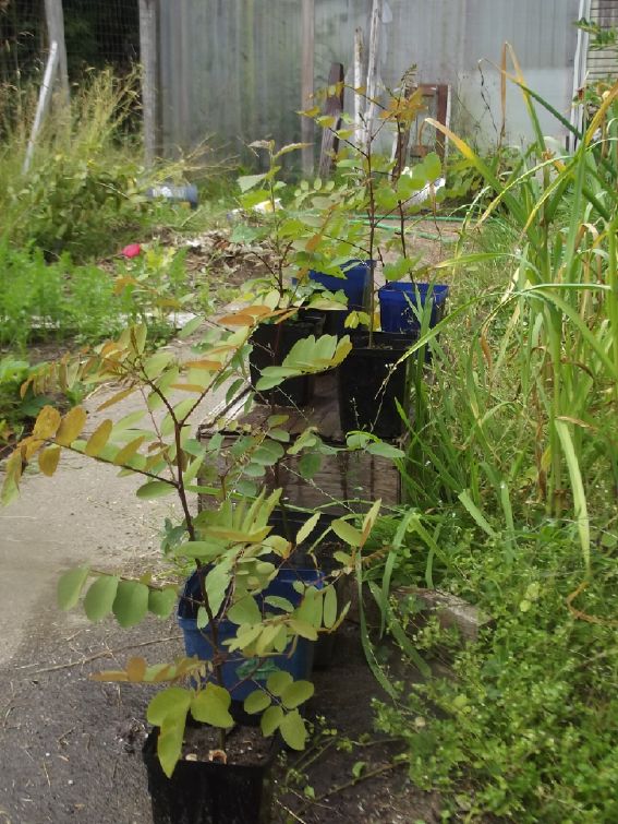
Black Locust and Birch trees grown from seed this year.
Next spring I'll plant some by the front fence with wire
stapled to the fence to keep the deer from eating them.
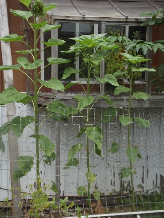
Again a few sunflowers by the south wall.
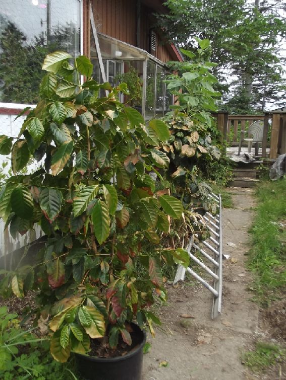
When the weather Finally turned nice and sunny in mid July I
brought out
the coffee trees from inside the patio door. Oops. Many leaves
got
badly
sunburned.
They have been dying and new leaves are growing to replace
them.

Strawberries in the south wall garden. The berries are good at
hiding.

Corn in the greenhouse, 21st. Only the ones from Dragonfly
Garden look
like
they might make cobs. The ones I planted just aren't growing.
Why?
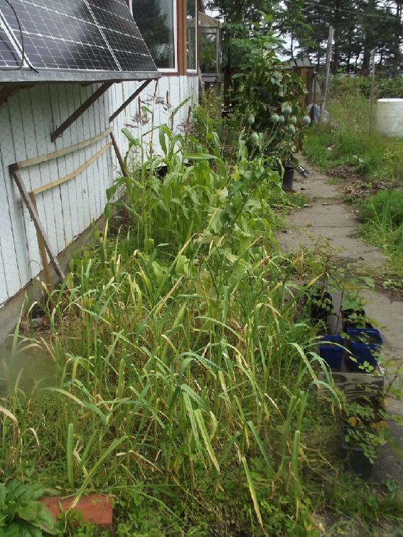
Also 21st: The corn I planted in a the big "cold frame" box
are
doing about as well as the Dragonfly ones in the greenhouse.
By August 7th they were a bit ahead, forming husks with
"silks" to catch the pollen.

Hidden fishpond with water lily. It hasn't grown a flower
since the
first year, when a deer ate it.
Unfortunately if it isn't well covered over raccoons will be
fishing
and someday
some otter will find it and clean out all the goldfish in a
brief time
on one day.
(That happened to my pond in Victoria twice.)
Instead it is occasionally visited by frogs or toads
that just stay a day or two and don't eat goldfish.
House Garden at the end of the month (July 31st):
garlic, corn growing tassels, seeded trees in pots, the coffee
trees in
pots.
Far right, back: small blueberry bushes.

House Wall Garden outside section at end of month:
Carrots that not many grew, now reseeded; board; carrots that
grew;
strawberries; onions (some from an onion bulb "set", some from
seed.)
(Where did that poppy come from?)
The Claw-Hoe: a Better Hoe
for
Weeding?
[23rd] I once bought the most useless hoe imaginable. The cutting
end
was formed of two overlapping circles. Either I was in an
experimental
mood or it was the only one in the store. (Who can remember from
about
1980? and why did I still have it?)
Of course no cutter dragging along the ground is or
stays
"razor" sharp, so the effect of the circular shape was to push the
weeds sideways into line with the crop plants, making them harder
even
to pluck by hand.
Last week I thought to buy a "normal" hoe for the
copious
weeds choking out my crops, but didn't. Instead I got the idea to
make
this one the opposite shape: straight and not sharp at the left
and
right sides, so as to go by the crop and not cut it, and concave
on the
end to form a point at the left and right edges. Then sharpen the
rear
face so as to cut the weeds as I drag the hoe backward through the
weeds, including right next to but not quite in line with, the
crop
plants.) I tried it out. Not bad. Actually it had a better working
angle on the handle than most hoes. When I went to do the right
side I
had an inspiration: cut it into triangles and points - almost
"tines".
Then dragging it through the weeds they would catch in the inner
slots
instead of escaping by slipping by underneath.

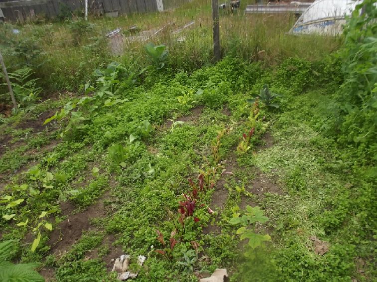 I can see my beets!
With this I was plucking up great gobs of chickweed
and
other weeds as I went. I had to keep dumping them aside, and for
the
first time ever I actually cut some good swaths through the thick
weeds
choking out my beets, beans, spinach and lettuce. and near the
peas and
potatos. The working end is pretty narrow left to right, but that
might
be good if you can get between "double rows" planted close
together.
And the cutting edge isn't very far to the back, so it has less
tendency to twist than most hoes.

I checked on line to see if there were any better
hoes
than those I've seen before. There was just one new type, with
tines -
sharper tines than mine. Like mine it worked at a more slanted
angle,
and it also had a horizontal slicer on the front that could
potentially
be useful. But it also had a couple more cutters on the sides
which
IMHO just would make it hard to get next to the crop plants for
close-in weeds without endangering them. I think the designer just
got
a little too fancy, to the detriment of the tines idea. Also in
the
video the user kept having to pull the weeds off the tines by hand
instead of dumping them off, so they may have been a bit too
pointed
and the slots too narrow, gripping the weeds too strongly.
So if I may be so bold as to claim another very tiny
"world's best", I think I've just made the most effective hoe. In
fact,
other than the above one I just looked at on line I've never seen
a hoe
that even was very effective before. I've always considered them
an
almost useless implement. Only my desperation to somehow pluck up
chickweed without plucking my crops led me to think of trying one
again
- and then to experiment.
Plastic Recycling 2.0 (to Make the
Motor
Housing)
(Note: The gallery of plastic images is in July in
Brief
- not many pictures in this text.)
[23rd] I was unable to buy a sheet of polypropylene (PP) a while
back.
So to make a PP housing for the motor, the next most obvious thing
would be to mold the plates out of old PP ropes washed up on the
beach.
That meant getting back to the long neglected plastic recycling
project
and finishing the plastic melting oven I started 2? 3? 4? years
ago.
Since that's outside work and it was a nice day, I
began.
When I left off, I had found that heating the oven - the shell of
a
freezer - not unexpectedly melted the foam insulation. I had
thought to
heat it up and melt it, then yank out the entire inside surface
assembly. Then I could replace the foam with higher temperature
insulation. I heated it to 120°C for a while, and then started
slashing
at the foam just inside the inner walls with a long, thin knife.
But it
didn't look like it would be an easy or clean job, and as I worked
I
thought up another idea. There was plenty of space. What if I put
higher temperature insulation inside of the inner walls so that
the
foam just didn't get all that hot?
So next I took a "cube" of steel racking (1 x 1 inch
square tubes) that I had got at the refuse station when I was
working
on it before to use as shelving to hold plastic molds up off the
bottom. I cut it to fit inside and make a single shelf near the
top of
the space. I also bent the oven element that heats it up to a
shape to
my liking that fit under the shelf unit.
Just two pieces of 22 x 27 x 3.5 inch insulation
covered
the inside walls. (The floor took one full piece. With the width
of the
shelf I had to split a piece down the middle twice, to 11 x 1.75
inches
to line the front and rear walls, so the other half was left over
to do
the ends and misc.)
So what I expected might take a couple of days I got
done
in one.
Later I cleaned and polished the large rectangle mold
(17
x 22 inches). On the last piece I had done (so long ago) I had
overheated some horrid black plastic in the previous oven with no
temperature control and it was solidly stuck to the alume. I did a
lot
of scraping with a chisel, and the then polishing took a long
time. It
did more smearing the plastic around thinly than getting rid of
it. But
eventually it was done.
Finally I took some crappy old rope and cut pieces to
the
length of the mold. 1030 grams of it. I looked forward to doing
the
melt in the temperature controlled oven, where I could leave it in
for
hours for the plastic to flow into the corners and voids, and hope
for
generally better results than I had been achieving before. But it
was
getting late so I left it. "Monyana (is good enough for me)", as
the
song goes.
[24th] I put the mold in the oven, put weights on it, and turned
it on.
I set the control to the temperature mentioned TE News #197
(400°F)
205°C. In 90 minutes or somewhat more it was only at 199. But the
plastic was oozing out and seemed a bit charred around the edges,
so I
shut it off and opened it. I was afraid the plastic would be baked
solidly onto the mold surface again, but it wasn't too bad.
Then I realized what the problem was: A
piece
of the insulation was covering the temperature sensor! So the oven
was
considerably hotter than the sensor indicated. It surely would
have
been up to temperature and beyond. The oven's outer foam
insulation
seemed to have weathered that pretty well. I peeled the insulation
away
to expose the sensor. I tried to pull it farther into the oven
space,
but it didn't seem to want to go. Good enough I hope.
The 1030 gram plate seemed pretty thin and one corner
wasn't filled. I decided to add another 600 grams of ropes on top
and
try the same piece over again. There was also a jute or hemp rope
within it. That one didn't melt at all.
In the evening I added 600 grams more plastic, with
the
original plate under and the new ropes over. This time the
temperature
reading rose much faster and the oven was at the setting (205) in
about
45 minutes. I left the mold in for a further 45 minutes at full
temperature, then turned it off and opened the lid. With the oven
not
overheating, the smell, which was awful and strong the first time,
was
barely objectionable. In addition it didn't seem like the plastic
material was deteriorating or sticking much to the mold - I could
probably re-melt it several times if need be.
The resulting slab however was pretty poor. It looked
more
like a routed contour map than a flat piece. I thought of three
possible reasons for the spotty filling and poor flow:
1. insufficient weight (~40 pounds) on the lid of the mold.
2. oven temperature too low.
3. insufficient melt time
Then the real reason occurred to me: there was simply
insufficient material to fill the space. The first time I had put
in
stand-off screws in the corners holding the top 1/2 inch above the
base. It seemed awfully thin and I had changed to 1/2 inch
stand-offs.
But it already had left a void corner with 1030 grams of rope
bits. I
had only added another 600 grams (=1630) and doubled the volume to
fill. Probably it should have had a total of maybe 2200 to 2500
grams.
Manyana!
[25th] I re-assembled the mold and put the piece back in, and
added
another 600 grams of old beach ropes material on top, making it
theoreticly 2230 grams. I cut and slipped two very thin slivers of
sheet metal into the cracks along two edges of the mold, about
3-1/2
inches tall, to help keep the lid from shifting when the material
placed in the mold caused it to be sit above the 2 inch edges
before it
started melting, which is most of the time, especially if you want
to
make a thick tile.
If it works well I may sand the top piece a little
and add
thin sheet to all sides. Four inch tall sides for the molds would
be
wonderful. (1 x 4 inch rectangular tubes? 'n' x 4 angle iron"? Do
they
even make such sizes? What's at the refuse station?)
I heated it for three hours this time, hoping it would
become
more uniform and air pockets would fill with plastic instead of
air.
The whole process, while still needing to be done outdoors for PP,
is
much more pleasant with an oven that holds the desired temperature
instead of overheating, scorching and vaporizing plastic and
warping
the alume alloy mold plates.
Ever since I originally started the project, I've
wanted
to make longer plates for dug-in garden surrounds to keep grass
roots
from spreading into the garden, but it suddenly occurred to me
that one
could melt tiles together with a heat gun to make a double size.
Or
even string several together to make a whole impermeable wall.
Well,
duh, so why did I make a larger plastic melting oven? But there
are
other pieces that would be nice to make larger or longer. (Eg,
plastic
fence posts?)
I have also realized that in the one "sample" garden
border I dug in before, I should have put the plastic Outside the
wire
deer fence instead of Inside. Then one could weed-whack the grass
right
up to the plastic without hitting the wire fence. With it on the
inside, there's a troublesome line of grass between the wire and
the
plastic that the weedeater can't get at.
The 2100 gram piece is by far the thickest I've done.
Putting it in the oven for 3 hours helped - it popped out of the
mold
easily. The lower surface was smoother. The upper surface was
still
full of sharp edged voids here and there, probably from trapped
air
bubbles.
I think I'll try making a few very small holes in the
top
piece for air to escape. I hope plastic doesn't fill the holes,
leaving
sprues and making it hard to separate from the plate.
[27th] I put 6 tiny holes in the top plate, about 5-1/2 inches
from the
edges and from each other. I tried to make a new plate with 1200
grams
of old ropes. It was a disaster! The plastic stuck to the mold
plates
like krazy glue, especially the bottom plate. When I finally
managed to
chisel the piece off it, there was all this horrid black plastic
here
and there, stuck solid - the same as in the last disaster. Except
this
time, I know I hadn't used any black ropes or pieces. It seems the
whitish-gray ropes turn black and stick to everything.
The 6 tiny holes were filled with plastic.
[28th] Another session of scraping and polishing black crud off
the
mold plates. (Isn't this where I came in?) And I drilled the
plastic
out of the 6 air holes. I'll stick to green, yellow and blue
twisted
ropes from now on. The "woven" whitish ones must not be
polypropylene.
(Nylon?)
[29th] I used 1 Kg of "almost new" green rope. Instead of being
easy, I
couldn't get it unstuck from the mold even with hammer and
chisels.
[30th] I tried putting it in a freezer, but it was no looser when
it
came out, whether still cold or warmed up.
[31st] I tried putting it in the oven at 75°C. While hot I managed
to
pry off one of the mold plates. When I tried the other, the
plastic
bent instead of popping off. I pried it out gradually in curved
form
inserting a chisel to scrape off many really well glued spots.
Then I
put it back in the oven at 75° on one of the plates, with weights
on
top, to flatten it out again.
It occurs to me that maybe 205°C (400°F) is too hot,
or at
least hotter than it needs to be, and that it might not stick so
badly
at a lower oven temperature. When I've cleaned and polished the
mold
plates again (sigh!) I'll try 180°, again for 3 hours. If it
hasn't
melted down properly, 190°. I hope I don't have to go up to 200°
again,
and that it doesn't stick at a lower temperature.
The piece was pretty much 1/4 inch thick, maybe a bit
over. There was a void corner. If I want 3/4 inch for the motor
stator
end plate I'll have to stuff in about 3 Kg of rope. I'll probably
have
to do it in two or three passes. Three or four inch walls on the
molds
would be great to hold more loose material - if I could find
something
to make them from.
[Aug 1st] I cleaned off and polished the plates - again. I decided
to
try polyethylene instead of PP ropes. (presumably HDPE - most
large
buoys on line are advertised just as "polyethylene") This time I
heavily greased the mold plates with some canola oil hoping the
plastic
wouldn't stick.
I
had
a
big
black
oval
fishing
float
from off the beach, which I had
dragged home and cut into pieces some time ago. The piece all
being
compound curved I cut them smaller on the bandsaw. I put 3 Kg of
this
material into the mold and the mold into the oven. I put the usual
40
pounds of steel weights on top and heated it to 180° for 3 hours.
The
corner with the most material stayed high. The piece popped out
easily
- what a change! It came out having not flowed much and was a
patchwork
full of big holes. Either it wasn't hot enough or it needed still
more
weight.
[August 2nd] The canola oil had turned into baked-on grease in
patches
on the mold plates and the piece. I did my best to clean them off
with
dishsoap and a scouring pad. Without going for heavy duty stuff
like
solvent I decided that was probably good enough. I cut off the
thick
corner and cut it into four or five pieces. I put it back in the
other
way up. I put the pieces into the holes.
This
time
I
scrounged
up
about
80
pounds
of weights. (I had to turn the
splitting wedges sideways - they didn't quite fit under the oven
lid
and propped it open. The double layer of weights was touching the
lid.)
I
repeated
the
process,
180°
for
3
hours.
It was better than the first
time, but mostly not squashed into a solid cube. The high corner
where
I cut some away to redistribute material didn't fill in. And with
80
pounds of weight! Sigh! 365°F, 186°C next time!
New
Grid-Tied
Solar Power System
[15th] BC Hydro approved my application. Now the electrician,
Adam, is
looking into the paperwork/inspections, parts et al.
My
(Old)
Solar
Power
System(s)
(My solar panels recent images - TE News #200)
The Usual Daily/Monthly/Yearly
Log
of Solar Power Generated [and grid power consumed]
Notes:
* All times are in PST: clock ~48 minutes ahead of local
sun
time, never PDT which is an hour and 48 minutes ahead.
* Unapproved AC/Grid Tied systems have been removed.
* House panels include four old ones on the roof (upper - total
rating
~ 1000W), two 305W on the roof, three 305W on the south wall below
the
roof, and one broken panel mounted verticly on the porch railing
(seems
to still work but a lot of shade there).
* Cabin DC includes the three carport panels and the two on a pole
in
the yard as well as the four on the cabin roof itself. All nine
are
305W.
* The wall, pole and porch panels are easily wiped off from the
ground
if it snows.
* Km = Nissan Leaf electric car drove distance, then car was
charged.
Car KWH does not add to or subtract from any other readings.
Recent fotos of solar panels, TE News #200:
House System Panels: House roof, wall (9 solar panels) -
Porch
(1 broken one - usually shady)
Cabin System Panels: Carport (3 - sunniest place on the
whole
property) - Pole (2 - shadiest place) -Faraday Cabin (4 - badly
shaded
in winter)
New Order of Daily Solar Readings (Beginning November 2024):
Date HouseDC, CabinDC => Total KWH Solar [Notable power Uses
(EV);
Grid power meter@time] Sky/weather, notes...
June
30th 539.18, 482.67 => 9.04 [10Km; 30152@21:00]
July
1st 543.58, 487.58 => 9.86
[30179@23:00]
2nd - missed - => (est) 9.50 [55Km; --
]
3rd 553.52, 497.41 => 10.27 [30229@20:30] Finally, ONE
sunny
day!
4th 558.38, 502.60 => 10.05 [90Km; 30248@21:30] ...then
mor
clouds & cool to cold.
5th 562.06, 507.06 => 8.14 [75Km; 30282@21:00]
&
mor
6th 568.40, 513.34 => 12.62 [35Km; 30301@19:30] &
mor
7th 571.25, 516.85 => 6.36 [30330@23:30]
& mor
8th 580.16, 522.90 => 14.96 [55Km; 30359@21:30] A
largely
sunny day(!) after a few AM rains. The batteries got a chance to
recharge plus I charged the leaf, around 9 KWH. The house solar
energy
pretty much kept up until the last 3(?) hours as the sun got low,
but
ended up only around 60% charged.
9th 589.33, 529.21 => 15.48 [20Km; 30383@23:00] Enuf sun
to
make up for chj. car 9KWH (yest) & 5 KWH.
10th 593.23, 533.50 => 8.19 [30411@23:30]
11th 596.91, 538.08 => 7.89 [30424@22:00]
12th 600.72, 542.29 => 8.02 [105Km; 30474@'24:00']
13th 603.09, 546.83 => 6.91 [45Km*; 30507@'24:00']
* car
started charge from house DC/solar
14th 612.18, 553.07 => 15.33 [30553@'25:00'] * Car finished
charging
in sunshine - had to turn off yesterday. It took all but 10 KWH.
15th 616.88, 556.20 => 7.83 [35Km*; 30556@23:00]
Sunshine!
Start of sunny, warm weather! * Car completely charged. Battery is
down
some. Disconnected cabin chj.ctrlr. because of apparent ultrasonic
noise. (to be moved outside of cabin!)
16th 623.07, 556.47 => 6.46 [30566@'24:00']
17th 628.33, 556.77 => 5.56 [55Km*; 30575@23:30] Charged
car
from solar ~10KWH
18th 637.52, 557.03 => 9.43 [85Km; 30593@20:30]
Charged
car 31% to 65% on solar (~7 KWH), then to 100% from power grid.
19th 644.12, 557.37 => 6.60 [75Km; 30611@22:30]
Charged
<1/2 way (5KWH) by solar 45%-62%(?).
20th 654.35, 557.70 => 10.23 [35Km; 30620@22:00] Chjd. car from
solar. Still sunny & warm!
21st ...must have missed it. => 0 Was it cloudy anyway?
22d 663.60, 558.22 => 9.25 [55Km; 30642@23:30]
Charged
car from solar : 9.7 KWH
23rd 667.19, 558.52 => 3.59 [30652@19:30] Top up
but
just running 36V lights.
24th 667.53, 558.58 => 0.40 [30669@'24:00'] Din't
use no
'lectricity, so din't genrate no 'lectricity.
25th 670.25, 558.85 => 2.72 [30685@23:00]
26th 672.51, 559.xx => 2.26 [55Km; 30701@21:30; 50Km]
1st
recharge from grid. Didn't recharge car after 2nd drive (64% left)
27th 678.66, 559.45 => 6.15 [35Km; 30720@23:30]
Start
recharge car (solar => 77%), drove (=> 44%), continued solar
charge, topped up from grid (81%=>100).
28th - missed - (est) => 3.50
29th 684.60, 562.48 => 5.47 (est from 8.97) [10Km;
30769@'24:30'] charged car on solar.
30th 690.74, 568.81 => 12.47 [55Km; 30790@20:00] charged car to
91%
on solar (voltage got below 38V)
31st 695.66, 569.45 => 5.56 [10Km; 30805@23:30]
Finished
charging car. (Cloudy,rain - House battery still not up.)
August
1st 703.69, 574.08 => 12.66 [90Km; 30833@'24:30']
Started
recharging car (from 34% left) on solar
2nd 710.38, 575.12 => 7.73 [45Km; 30854@21:00]
Contd.
chj. car to 72% then switched to grid charger. (Then drove again)
3rd 712.92, 577.46 => [45+45Km; 30874@21:00]
4th 717.25, 578.47 => [30891@23:00]
5th 719.37, 579.82 => [30912@20:00]
6th 722.93, 582.50 => [55Km; 30931@21:00] Charged car on
solar by 7.5 KWH, finished from grid. (4 KWH?)
7th 728.64, 583.32 => [30960@22:00]
Chart of daily KWH from solar panels. (Compare July 2025 with June 2025 & July
2024.)
Days of
__ KWH
|
July 2025
(18 Collectors,
DC/ Batteries.)
|
June 2025
(18 C's - DC/
batteries only)
|
July 2024
(18 C's - Grid
Ties & DC)
|
0.xx
|
2
|
|
|
1.xx
|
|
|
|
2.xx
|
2
|
|
|
3.xx
|
2
|
|
|
4.xx
|
|
1
|
|
5.xx
|
3
|
|
|
6.xx
|
5
|
|
2
|
7.xx
|
2
|
3
|
3
|
8.xx
|
3
|
2
|
|
9.xx
|
4
|
6
|
3
|
10.xx
|
3
|
5
|
3
|
11.xx
|
|
5
|
|
12.xx
|
2
|
3
|
5
|
13.xx
|
|
4
|
1
|
14.xx
|
1
|
1
|
3
|
15.xx
|
2
|
|
1
|
16.xx
|
|
|
1
|
17.xx
|
|
|
2
|
18.xx
|
|
|
|
19.xx
|
|
|
|
20.xx
|
|
|
2
|
21.xx
|
|
|
|
22.xx
|
|
|
2
|
23.xx
|
|
|
2
|
24.xx
|
|
|
|
25.xx
|
|
|
1
|
Total KWH
for month
|
243.26
|
316.55
|
563.61
|
Km Driven
on Electricity
|
1035.8
@8.2 Km/KWH
= 130 KWH
|
1038.9
@8.2 KWH/Km
= 130 KWH
|
1348.1 Km
~180 KWH
|
Things Noted - July 2025
* The crappy weather, following a miserable May & June, seemed
to
finally end mid July.
* Disconnecting the charge controller on the 15th showed that the
power
monitor is not well zeroed. This gets added to the charge
recorded. I
decline to make daily cumulative adjustments and must let the
readings
be off by this small daily amount. (Could subtract ~30*~30=~900 WH
from
monthly total?) Oh wait!
Isn't that 300 WH/day? Not trivial! Now what? [See
"Puzzling
Readings" in "Month in Brief"]
* The summer sun sure shows that power goes to waste if it can't
be fed
into the utility grid. (See July 2025 vs July 2024 in table above)
Not
needing heat, the only substantial use of
the solar power is to charge the electric Leaf, and usage, and
hence
recharging, is actually lower than in the spring when heat was on
using
much of the available solar.
Monthly Summaries: Solar Generated KWH [& Power
used
from grid KWH]
As these tables are getting long, I'm not repeating the log of
monthly
reports. The reports for the first FIVE full years (March 2019 to
February 2024) may be found in TE
News
#189,
February
2024.
2024
Month: HouseAC + DC +Carport+Cabin[+DC] (from Aug 2024)
Jan KWH: 31.37 + 3.14 + 16.85 + 16.82 = 68.18
[grid
power used: 909; car (very rough estimates): 160*]
Feb KWH: 96.52 + 2.36 + 49.67 + 52.98 = 201.53 [grid: 791;
car:
130]
FIVE full Years of solar!
Mar KWH 150.09+ 1.63 + 93.59 + 92.50 = 337.81
[grid:
717; car: 140]
Apr KWH 181.89+35.55 +123.50+142.74 = 483.68
[grid: 575; car: 140]
May KWH 129.23+67.38 +109.6 +126.32 = 432.53
[grid: 405; car: 145]
Jun KWH 152.54+51.02+118.99+141.17 = 463.72
[grid: 420; car: 190]
July KWH 174.22+30.53+111.19+128.62 = 444.56
[grid: 386; car: 165]
Aug KWH 221.99+ 2.63 +142.49+151.67+ 5.78 = 524.56 [grid:
358;
car: 180]
SeptKWH 120.98+ 2.49 + 83.50 + 19.10+ 39.95 = 266.02 [grid: 662
(yowr!); car: 155*]
Oct KWH 78.48+ 7.29 + 64.39 + 7.52 + 40.75 =
198.43
[grid: 711; car: 120*]
Nov KWH 19.63+12.19+ 23.90 + 3.35 + 25.62
=
84.69 [grid: 900 (ACK!);car: 110*]
Now solar is charging
batteries only. 2 DC systems: house, cabin.
Dec KWH 20.37 + 16.76 = 37.13 [grid: 1866 (using electric
heat -
awg!); car: 120*]
2025
Jan KWH 35.02 + 26.30 = 61.32 [grid: 2136 (electric
heat
OW!); car: 120*]
Feb KWH 55.43 + 39.00 = 94.43 [grid: 1937; car: 100*]
SIX full Years of
solar!
Mar KWH 115.13 + 87.41 = 202.54
[grid:
1860; car: 155* KWH]
Apr KWH 126.25 + 120.36 = 246.61 [grid: 1246; car: 100*]
May KWH 147.08 + 186.24 = 333.32 [grid: 1354; car: 150*]
Jun 145.58 + 170.97 = 316.55 [grid: 959; car: 130*]
July 156.48+ 86.78 = 243.26 [grid: 653; car 130]
* Car consumption comes from solar and or
grid: it
does not add to other figures. (Just from grid from Nov. 18th.
2024 on
-- much of it from off-grid solar as of June 2025.)
Annual Totals
1. March 2019-Feb. 2020: 2196.15 KWH Solar [used 7927
KWH
from grid; EV use: -] 10, 11, 12 solar panels
2. March 2020-Feb. 2021: 2069.82 KWH Solar [used 11294 KWH from
grid;
EV use: - (More electric heat - BR, Trailer & Perry's RV)] 12
solar
panels
3. March 2021-Feb. 2022: 2063.05 KWH Solar [used 10977 KWH from
grid;
EV use ~~1485 KWH] 12 solar panels, 14 near end of year.
4a. March 2022-August 2022: in (the best) 6 months, about 2725 KWH
solar - more than in any previous entire year!
4. March2022-Feb. 2023: 3793.37 KWH Solar [used 12038 KWH from
grid; EV
use: ~1583 KWH] 14, 15, 18 solar panels
5. March 2023-Feb. 2024: 3891.35 KWH Solar [used 7914 KWH from
power
grid; EV use: ~1515 KWH] 18 solar panels
6. March 2024-Feb. 2025: 3428.88 KWH Solar [used 12773 KWH from
grid;
EV used: ~1685 KWH]
Money Saved or Earned - @ 12¢ [All BC residential elec.
rate] ;
@ 50¢ [2018 cost of diesel fuel to BC Hydro] ; @ 1$ per KWH
[actual
total cost to BC Hydro in 2022 according to an employee]; or maybe
it's
62 ¢/KWH [according to BC Hydro at Renewable Energy Symposium
Sept.
2024]:
1. 263.42$ ; 1097.58$ ; 2196.15$
2. 248.38$ ; 1034.91$ ; 2069.82$
3. 247.57$ ; 1031.53$ ; 2063.05$
4. 455.20$ ; 1896.69$ ; 3793.37$
5. 466.96$ ; 1945.68$ ; 3891.35$
6. 411.47$ ; 1714.44$ ; 3428.88$
I had to disconnect the system from the grid in
November
2024. These two now independent installations (house, cabin) will
continue to run their 36 volt DC systems and I'll see how I can
most
effectively utilize the available solar energy with the limited
available storage.
http://www.TurquoiseEnergy.com
Haida Gwaii, BC Canada