Turquoise Energy News #210
Covering
Research & Development Activities & Projects of
November 2025
(Posted December 2nd 2025)
Lawnhill BC Canada - by Craig Carmichael
[Subscribe: email to
CraigXC at Post dot com ; request subscription]
Main URL TurquoiseEnergy.com Also at craigcarmichael.substack.com
Month
In "Brief" (Project Summaries etc.)
* New Cylindrical Battery Design (for organic Cu/Zn cells) - OLAHP
Air Compressor Test - Faraday Cabin Construction
In Passing
(Miscellaneous topics, editorial comments & opinionated rants)
* Planetary Management: Citizen Appeals Tribunals
* Scattered Thots
- Detailed
Project Reports -
Electric Transport - Electric Hubcap Motor
Systems - no report (will I ever find time to
finish the next motor?)
Other "Green" &
Electric Equipment Projects
* A New Tech ! Resistance Heating Elements made With Power
Diodes (advantages over resistance wire)
* Open Loop Air Heat Pumping (small progress again)
* Faraday Cabin Construction
* Yet More Electrosmog/Tinnitus Culprits
New Battery R & D (back in the
news!) - Organic Copper Crush Experiment - Promising new
cylindrical cell design - Newer New Cell Design
Electricity
Generation
* New Grid Tied System - back on track?
* Old System - The usual Latest Daily/Monthly Solar Production
log et cetera - Monthly/Annual Summaries, Estimates, Notes
November in Brief
 Pivoting Vane Air Compressor,
assembled. It should be super efficient.
Pivoting Vane Air Compressor,
assembled. It should be super efficient.
Sometime near the start
of the month the travesty of the destruction of a BC ostrich farm
got me thinking about citizen appeal boards again. I'm quite
pleased with what I came up with, below in In Passing.
Anyone could start a citizens' tribunal - it doesn't require
government action.
There's really no gardening report this month. I kept
the houseplants, greenhouse and some trees watered. I dug up some
clumps of grass and weeds, and some potatos - some to eat, some
for seed in the spring in case the ground freezes. A cabbage in
the greenhouse has grown a head that I'm about to harvest. A few
cherry tomatos and a couple of peppers are coming in the house,
along with coffee seeds. The avocado is getting quite tall.
There was a warning of some nasty solar storm coming.
Space weather! In a video a CME seemed to disturb about 1/3 of the
whole face of the sun. A space launch was cancelled. On the 12th
there was frost but a beautiful display of northern lights.
(almost actual midnight - "24:30" PST) At first great sheets of
pale light zipped across the whole sky in different directions -
all in a second or less. Mostly the northern half of the sky Then
pillars of light arose from the northern (?)horizon, reaching up
into the sky. But at my place the northern horizon is hidden
behind tall trees. I decided to drive to Jungle Beach where I
could see better to the north. In the 10 minutes that took, clouds
had moved in to the north and east and the lights seemed to have
faded too - a disappointing ending to a great display. Bed time!
[18th] I have been meaning to post all issues of Turquoise Energy
News to craigcarmichael.substack.com . I finally did 2008, #1 to
#12. I backdated all the publication dates to the original posting
date, which is available but requires some manual steps for each
issue, so I was working on it for over an hour. 12 issues per
year, 18 years... I should be done by 2027!
New Chemistry Batteries
I tried pressing the organic material with
copper/monel as a flat plate electrode. It seemed fine but still
had high resistance. I didn't get any farther. Then by the last
third of the month I came up with a new idea for constructing
cylindrical batteries. I picked my smallest ointment jars as a
suitable outer case that wouldn't leak. I started working on it
and 3D printed a cylindrical "basket" in ABS to hold the
electrodes separate. Then I realized reversing the position of the
electrodes would solve some construction problems. Without
assembling the first design I revised the basket and other things
and started on the second one, with the "+" electrode on the
outside and the zinc in the middle.
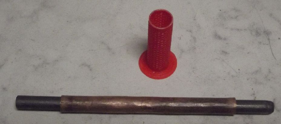
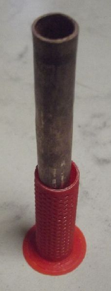
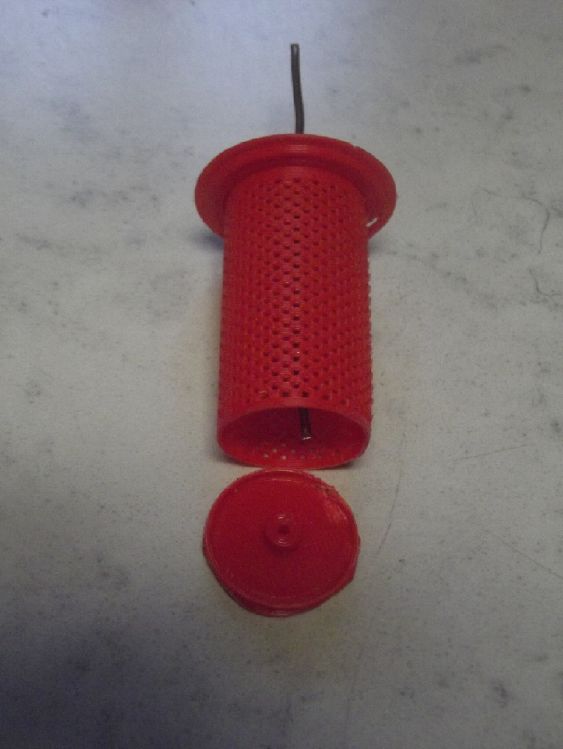
From Outside In:
ABS jar container.
Conductive graphite 'gasket' current collector inside the rim
of the jar.
Crunched positive electrode powder material.
Zinc (negative) basket (separator paper not yet placed inside
the rim).
central wire current collector for the zinc.
Two pieces of pipe to crunch the positive powder down
into a cohering layer just inside the graphite around rim.
Pressing the 'ears' of the outer pipe compacts the powder.
Withdrawing the inner pipe afterward leaves a space the
same diameter as the inner basket to be inserted.
Separator paper & zinc mix before gluing top on.
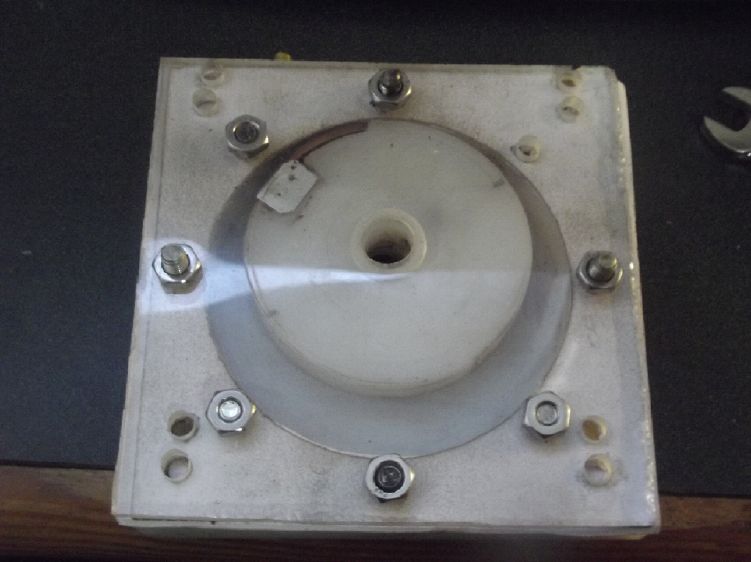
Cell being tested
I drilled a hole to hold the cell in a block of wood so
the test
leeds wouldn't tip the cell over or drag it off the
bench.
So far tests with the organic copper/monel mix don't
seem promising.
OLAHP Air Compressor Test
 Not wanting to leave the project
completely behind, I got the compressor together, mounted it on
the motor and ran it. It didn't seem to push much air and the
rotor seized to the cylinder after it stopped. It seemed a tiny
piece of UHMW, probably scraped off by the pins holding the vane
assembly, had melted and glued them. I didn't get farther than
getting it off and seeing what the problem was.
Not wanting to leave the project
completely behind, I got the compressor together, mounted it on
the motor and ran it. It didn't seem to push much air and the
rotor seized to the cylinder after it stopped. It seemed a tiny
piece of UHMW, probably scraped off by the pins holding the vane
assembly, had melted and glued them. I didn't get farther than
getting it off and seeing what the problem was.
Diodes for Resistance Heating 
I ran across a new (2019?) idea of using diodes for
resistance heating elements instead of nichrome resistance wire. I
was puzzled why anyone would do that, but it has advantages with
non-exact power sources - solar panels or batteries.
With a solar panel, if the number of diodes is chosen
so that their forward voltage drop equals the MPP voltage of the
panel, it's almost like a solar charge controller. They will
extract the maximum available heating watts from the panel all
day, the voltage always staying near MPP regardless of how much
current the panel can source. With resistance wire, if the panel
can't put out enough current, the voltage is dragged down. Watts =
Volts * Amps, and little heat is produced except at noon on sunny
days.
With a battery, the diodes could be chosen so that
the heaters will put out less and less as the battery gets lower,
pretty much stopping without fully draining the battery. This not
only protects the battery from overdischarge, but can do so while
there's still power left to run lights and other lower power
appliances. It could also be set up as a "dump load" that only
supplies heat when the battery is at full voltage and more power
is coming in. At least, that's the theory. How well the diode
strings can be matched to the 36V LiFePO4 battery will be the
subject of experiments. Diode Vf is unfortunately not
entirely a constant, ranging typicly from .7 to .9 or even 1 volt
depending on current.
As well as space heating, I hope to try making an
alume plate 'stove burner' or 'hot plate' for off-grid cooking
with diodes, and maybe a hot water tank heater. At 36 volts such
heaters might take about 55 diodes. I've ordered 60 power bridge
rectifiers, which (for this purpose) each have two pairs of
parallel diodes in an alume case that can bolt to a heatsink.
Faraday Cabin Construction
I decided I had put the stairs in a bad place - that
the bottom steps shouldn't stick out into the east side of the
building. Kind of late, but I decided to shift them over by three
feet. First I had to move the 36V DC electrical board/panel under
the stairs by that amount, and of course some wires. Luckily I
don't have a lot of wires yet, and most of them were long enough
for the move. Of course after the move the landing upstairs didn't
quite match the door. (Luckily I had made the landing 5 feet long
with the door at the far end, or moving the stairs wouldn't have
worked at all. I'd have had to change the whole wall to move the
door.) I turned the door around so one wouldn't step right out
onto the top step instead of the landing. I have yet to cut the
landing shorter. It goes way past the door now and needlessly
impinges on the space below. And now the upstairs room light
switch is on the wrong side of the door and needs to be moved.
That should be fun as the wire to the light is inaccessible in the
finished ceiling.
In
Passing
(Miscellaneous topics, editorial comments & opinionated rants)
Planetary Management: Citizen Appeals Tribunals
In BC, on a ranch with hundreds of magnificent
ostriches, a few of the birds caught a disease and died in January
2025. The rest remained healthy or recovered. Tests determined
that the disease was infectious avian influenza and the Canadian
Food Inspection Agency (CFIA) wanted to kill all the birds. The
owners fought back and the case went to court in May and again in
August. The courts upheld the law and the CFIA. In November, long
after the outbreak had ended and in spite of much public protest,
the CFIA denied the owners access (even having one arrested for
entering and feeding the hungry birds) and finally shot all the
ostriches.
This was an experimental open ranch, not a "factory
chicken" operation with thousands of hapless birds crammed 24-7
into a closed building in which disease could spread like
wildfire. The sick ostriches were separated from the healthy ones.
The outbreak was closely monitored and studied as part of the
experimental R & D. The birds that recovered would even be
immune. Seemingly the action ten months later was a useless
bureaucratic exercise in futility resulting in senseless
destruction of a fine resource and a severe violation of private
property rights. The ostrich farmers are not even permitted to get
more ostriches in case the influenza virus has infected the soil.
Thus their entire enterprise is ruined. Certainly no good
arguments for doing these things reached us, the BC and Canadian
public. It has been called a serious crime and many feel that way.
Certainly no one will ever dare to try to start an ostrich farm in
Canada again.
What might have been done?
Here's where my idea of citizen appeals tribunals
should have been useful. Courts rule on legality, not on morality
and whether a law or bylaw has been reasonably applied, mercy for
the affected, or the consequences of enforcing it. Had I been in
contact with the affair, I think (admittedly in retrospect) that I
would have liked to strike such a committee even without any
official sanction - perhaps five or seven people to hear the case.
I think I'd have called it:
Canadian
Citizens' Tribunal
hears specific citizen
appeals in individual cases of seeming bureaucratic
overreach or inappropriate application of laws, bylaws or
statutes
After getting the volunteers - who I'm sure would be
forthcoming for such a concern and probably for many others - we
would sit and hear the case. (I would hope for a lawyer and a
veterinarian or two on board. Maybe even a virologist?) We would
invite both the plaintiff (the ostrich farmer family) and the
prosecution (the CFIA wanting to kill the ostriches) to be heard
and or to present written briefs. We would give each party a
chance to respond to the other's submissions. A decision wouldn't
be made in a day without reasonable chances for feedback and for
deliberation within the tribunal. There would doubtless be at
least two or three sittings in most cases. We would invite media
to hear (at least) the final written verdict including the main
reasoning behind it, and send copies to elected representatives.
We would not contest laws, bylaws or statutes as such, only
individual cases. We would adjudge the applicability of the law,
its reasonableness and fairness, only as applied for the present
case, and we could forecast the likely consequences of enforcing
it or not, only in the present case. Thus the tribunal would have
no responsibility to consider or decide on anything except the
case at hand on its own overall merits.
I think we have a pretty good feel for the ostrich
owners' side. Their lifework and livelihood was destroyed by the
federal government civil service by an action that seemed to make
no sense to the public. No moral or physical case for the
reasonableness or necessity of the slaughter after the birds had
long since recovered reached the public ear. On the other side, if
the CFIA presented a good case to the tribunal that would also be
considered. CFIA would be under no legal obligation to respond to
an "unofficial" tribunal, but if it didn't, it would certainly
suggest its only case was "Well, it's the law, and we intend to
uphold it! If we start making exceptions, there would be no limit
to the carnage in bird populations."
The argument that an exception could result in more
exceptions doubtless carries some weight in regular courts of law
and in bureaucratic circles. But since tribunal appeals apply only
to the specific case in question a victory for the ostrich owners
would not set a legal precedent and could not be applied to other
cases. (This aspect of tribunal decisions should be clearly
pointed out in communications including as a footnote in decisions
by the tribunal.)
In spite of having no formal basis for its existence,
a volunteer citizen tribunal would carry moral authority. The more
such tribunals conduct themselves like fair and proper courts, and
the more cases heard and adjudged even handedly - and in
reasonable mercy to the plaintiffs - the more legitimacy and
respect they would acquire. They could become a new institution
assisting with fairness in societal decision making.
It might also make an assessment of the damages that
would result to the plaintiff(s) in the event of enforcement and
suggest a financial compensation amount to be paid if enforced.
Some tribunals might be temporary, addressing a
single issue and then disbanding, or some might find there are
sufficient appeals to warrant continuing existence and regular or
irregular sessions.
What benefits would such moral legitimacy bring?
Almost no one actually wanted to see the ostriches slaughtered,
but no one felt they had the authoritative medical expertise or
bureaucratic or legal justification to say "No!". A well
considered citizen tribunal decision of "No!" would give elected
officials including federal, provincial and local officials -- the
area's MP, MLA and regional district rep, or even the prime
minister and the premier -- a fair basis for instructing the civil
service, here the CFIA, "Desist!" It might even be considered by
the department itself as sufficient cause or excuse to desist with
action, even if not so ordered "from above".
Scattered Thots
* Why do many people have a lot of "skin tags" (skin polyps)
around their neck area? Why do makers put rough, scratchy collars
on otherwise soft shirts? (Skin tags are "benign tumors" but are
apparently not good for you. Long ago I got rid of a zillion of
them - more around my neck than everywhere else - by rubbing them
about 3 times daily with castor oil and baking soda, for a couple
of days to a week each. I kept jar caps of it by my bed and in the
bathroom - wherever it was handy.)
The tea shirt I have on has a tag/label behind my
neck that feels like it might as well be fiberglass.
* NGO's: Non-accountable Government Opaqueties
* When one innocent person is oppressed, acted against without
absolutely compelling reasons, even in the name of "the greater
good", all innocent people are oppressed, because the greater is
made up of individual persons.
ESD
(Eccentric Silliness Department)
* In trying to create wheels primitive man found that "round" was
a good roll model.
* Gold is said to be really heavy but it has been rising like a
balloon. (Over 5000 $C per 31.1 gram piece at the moment. IIRC I
bought a piece in 2012 for 1350 $.)
"in
depth reports" for each project are below. I hope they may be
useful to anyone who wants to get into a similar project, to glean
ideas for how something might be done, as well as things that
might have been tried, or just thought of and not tried... and
even of how not to do something - why it didn't work or proved
impractical. Sometimes they set out inventive thoughts almost as
they occur - and are the actual organization and elaboration in
writing of those thoughts. They are thus partly a diary and are
not extensively proof-read for literary perfection, consistency,
completeness and elimination of duplications before publication. I
hope they may add to the body of wisdom for other researchers and
developers to help them find more productive paths and avoid
potential pitfalls and dead ends.
Electric
Transport (No Reports)
Other
"Green" & Electric Equipment Projects
A New Tech !
Resistance Heating Elements made With Power Diodes
(advantages over resistance wire)
[27th] I watched a couple of videos by Dave, Youtube channel
"Solar Power Edge". Dave has some good and interesting ideas. This
one seemed rather odd at first glance: to make a heater using the
forward voltage drop and heat from diodes instead of resistance
wire. But on inspection it has advantages.
A typical (non-Schottky) diode doesn't conduct
electricity in the forward direction until the voltage reaches its
junction voltage of about .7 volts. Above that, it conducts more
and more current until at around 1.0 volt it may be conducting
tens of amps or even 100's, depending on the specs of the diode.
He was using this with about 25 diodes in series to be 25 unit
heat elements of a heater, running directly off a 17 volt (at
maximum power point, MPP) solar panel.
Solar panels also have diode junction voltages, about
.5 volts per cell. So a 36 cell solar panel is around 18 volts if
light is shining on it, less a little bit if MPP current is being
drawn from it - the MPP voltage.
Now say we have 1200 watts of solar panels. These may put
out 1000 watts at MPP at the equator on a cold day in the dry
season if there are no jet trails. So we connect a 1000 watt
heater of just the right resistance and get 1000 watts of heat.
Perfect! But a jet trail goes by and the afternoon wears on so the
sun angle becomes oblique, and at the MPP voltage it can only put
out, say, 31.6% of maximum current. Our resistance heater is going
to drag the voltage down to 31.6% of MPP voltage. 31.6% amps times
31.6% voltage isn't 316 watts, it's 100. So our heater is only
putting out (purely by coincidence) 31.6% of what it should be
because of overloading the solar panel. The less the light, the
worse it gets. If the panels can only put out 10% of full current,
they will be dragged down to 10% of MPP voltage and the heat
output will be 1% instead of 10%, 10 watts instead of 100 - no
heat to speak of! (All very approximately, I'm sure.)
Now instead we make our heater from a diode bridge.
We make it similarly with just the right number of diodes so that
with 1000 watts MPP from the solar panels, there's 1000 watts of
heat coming out of the diodes. And maybe the diode junction
voltage at this level is, say, .8 volts. So if the panels were 36
volts MPP, that would mean there were 45 diodes, each dissipating
22.2 watts.
Now the sun drops and we're at that 31.6% current
level. The forward voltage drop of the diodes drops to .75 volts.
The solar panels' voltage output drops to (.75/.80*36=) 33.75
volts, (33.75/36 =) 93.75% of MPP voltage. The heat will be
(93.75%*31.6% =) 297 watts - almost the theoretical 316. At the
10% level the diodes might drop .7 volts each, making the figure
(87.5% volts * 10% amps =) 87.5 watts of the 100 watts theoreticly
available.
Or, by time of day according to Dave:
That's quite a difference. In fact, one might call it
a whole exciting new heating technology!
A More Typical Off Grid Heater Design?
Myself, I use the most heat at night and lots of
winter days on the PNW/BC coast aren't sunny, so connecting direct
to a solar panel isn't going to cut it. So I'd plug the heater(s)
into the 36 volt battery system wall outlets like everything else.
I had been trying to make a 'low voltage cutout circuit' mostly
for electric heaters, as dump loads or just to shut them off if
the battery got low. Now my idea instead is that if the battery is
delivering over 40.5 volts (max is 40.8) the heaters should run at
full power, but if it drops to 38.5 volts (~25-30% charge), the
heater(s) should be almost off, delivering just a few watts and
not draining the rest of the power. Maybe total shutoff by 38.0
volts? It would be completely automatic and virtually failure
proof.
Sidetrack on batteries
The exact figures and hence number of diodes do
of course depend on battery type. I am using LiFePO4. 12 cells '36
volts' herein -- generally sitting in the narrow no-load range of
38.4 to 40.8 volts. (Many people charge these at 42 volts, but
they will soon drop back to 40.8 when the charge is removed. I
charge at only 40.8 to make low stress and hopefully have them
last considerably longer. But then they rarely get right to 100%
charge - 90-95% at the end of the day is more usual. Then of
course the voltage will be lower at night depending on loads as
well as charge state. I looked for info on voltage versus battery
temperature, a concern with Li-Ion types, but was unable to find
any info. Dang! How did I get writing on about batteries when the
article is about diode heaters?)
Moving On...
[28th]
I
ordered sixty 50-amp bridge rectifiers. Each one has four diodes
which can be used in series-parallel between the "+" and "-"
terminals. So two diode drops per unit, and half the increase in
forward voltage with current because there are two sets in
parallel. 38.5 volts with .7 volts forward drop, where the diodes
start turning on, is 55 diodes or 27.5 bridge rectifiers. 40.5
volts over 27.5 bridges would be .736 volts, which will conduct a
lot more current than .70 . How much more remains to be seen. I'm
hoping to be able to tailor the specs to get, say, a 500 watt
heater that will taper off to nothing if the battery gets fairly
low, and never kill it.
500 watts/27 bridges = 18.5 watts per bridge. (a half
used bridge would be 9.25 W.) Of course they will need to be
mounted on metal - perhaps alume heatsinks. If it's a big enough
plate it can be convective heating. If not there'll have to be a
fan. A nice housing, a power switch, a tipover switch and a
thermostat would be assets. An extra diode bridge or two in the
series and a switch(es) to short them out could provide lower
power settings. Then I might be able to go for a heater capable of
700/400/200 watts, 700 being about the maximum for a 36 volt, 20
amp wall outlet circuit. Exact number of bridge diodes will be
subject to experimentation, of course. There are line voltage
losses, varying diode specs, etc. to consider.
I'd feel a lot better about running DC/solar/battery
electric heat if I knew it couldn't kill the battery if (sooner or
later) I forgot and left it/them turned on. Instead with the right
number of diodes they could make good "dump loads" for times of
excess power.
One might also consider making hot plates for food
and water heater elements made with these components. For the
cooker, the diodes could be heatsinked direct to an alume "burner"
plate. This would transfer the heat to the pot really well and it
might well be more efficient than an induction cooker.
For a water heater the diode elements might be
mounted directly on the side of the tank (especially if it was
copper), again with high efficiency and no need for holes in the
tank.
Sixty bridges is enough to try out two 36 volt heating
elements with a few to spare. The 60 were well under 100 $C.
But wait! There's More!
An interesting associated idea was that the heater
diodes could be used as voltage regulators in place of DC to DC
buck (reducing) converters. One could tap into the diode string at
any desired voltage point in .7 volt steps. As long as the device
being powered used less current than the diode heater was using,
some of the current would flow through the device being powered
instead of the diodes being bypassed, and the voltages would stay
almost the same. One could thus tap off 7 diodes to get (7 * .7 =)
around 5 volts to charge a USB charged device, or about 19 or 20
to charge a 12 volt battery; 17 to 20 to run a 12 volt LED light.
Almost a lab variable power supply, with no smarts or controls at
all! It would however be drawing current and heating the whole
time while in use. That's better in winter than in summer!
Later I looked it up. The diode heater idea wasn't
original with Dave.The earliest reference I found was a 2019
research paper: Hot Diodes!: Dirt cheap cooking and
electricity for the global poor? by six authors. It seemed
others started picking up on the idea about 2024. The original
authors had used cylindrical diodes. Later the improvement of
using power diode bridges with heat transfer cases had arisen.
[29th] Continuing on the theme, what about that 'hot plate' or
'stove burner'? One could bolt the diodes' cases to the bottom of
a round alume plate with flat head bolts. The top would be the
cooking surface. One would definitely need to attach a temperature
sensor or cutoff switch/thermostat and have the 'burner' shut off
below the maximum operating temperature of the diode bridges.
(pretty sure that's well over 100 degrees C. Otherwise you
couldn't boil water.) The pot or pan would of course sit on top of
the plate. Aluminum itself heats (and cools) fast, absorbing very
little of the heat energy itself. Most of the energy would
transfer right into the pot.
The bridges, KBPC5010's, are 28.8 mm square. A square
of 5 by 5 (25) bridges would thus be 144 by 144 mm. That would
require a round alume 'burner' size of at least eight inches (204
mm) diameter. We might need 27 or 28 bridges, but the 2 or 3
center rows could be offset to fit an extra bridge without needing
to increase the diameter.
Even in the absence of a "smart" timer control, if
the burner was left on at night it would put out less and less
heat until it virtually stopped when the battery got down to about
3/4 drained. For solar that's indescribably better than stopping
after the battery is totally dead! whether or not a "balance
charger" prevents critical battery damage. Same thing with space
or water heaters.
[30th] I thought to order a few thermostatic switches of 110, 115,
120, 130 & 135 degrees C for the hotplate. And maybe for a hot
water heater. (They were out of 125 degrees, which would have been
my first choice. But I didn't bother trying another store.) If 135
degrees isn't hot enough, the burner idea may be "out", since the
bridges are only rated to 150 degrees.
Open Loop Air Heat Pumping (OLAHP)
[27th] I (at long last) cut a second
thick paper gasket and put it on. Now the piston was loose instead
of binding. (Art paper was probably not an ideal gasket choice. Oh
well.)
I
fit
it together and did up the bolts. The piston was still loose, but
the clearance front to back was maybe .02 inches.
I mounted it onto the motor. It ran,
but was stiff. It didn't seem to have enough air pressure at the
little pipe to push my finger aside. After running I found the
piston was seized. Not the motor shaft, the piston itself.
[30th] I disassembled the
unit. I took it right off the motor with the piston still stuck. I
could pry it up anywhere and flex it a bit. It was stuck at just
one point. It finally popped off. It seemed a tiny bit of UHMW had
melted and glued the rotor to the cylinder. The pin holding the
vane was rubbing (I can see the groove) and must have melted it.
The pinned-in alume piece with a pin holding the vane are the
parts I have the least confidence in. There's no clearance to put
in something more robust. I'd be happy to come up with a better
mechanism.
"Faraday
Cabin" Construction
Wall, Electrical & Stairs
[15th, 16th] I decided I had placed the stairs to the bedroom
badly - that the bottom steps shouldn't stick out into the eastern
half of the building. I finally decided to "bite the bullet" and
move them over. To do that, I would have to "slide" them 3 feet
along the center wall they went up alongside. To do that I would
also have to move the 36V DC main electrical board by the same
amount. Then I would want to reverse the door because one would
almost be stepping on the top step instead of the landing coming
out of the bedroom. If the hinges were on the other side, it would
be safe coming out. It would be a nuisance, but still doable.
Luckily I had made the top landing 5 feet long and put the bedroom
door at the far end. If the door had been any farther east, the
whole idea would have been impractical.
 First I slid the battery over 3 feet.
I had to pry the bottom plywood up and slip something under it,
and pull it in stages. Heavy! (135 pounds?) Then moving the wall
panel board involved unscrewing everything from it because I had
screwed the 3/4 inch plywood to the wall studs and then screwed
1/2 inch gyproc onto that for fire safety in case of sparks or hot
spots. The gypoc had to come off to get at the screws holding the
plywood. And of course the components were screwed through the
gyproc into the plywood. But I got it mostly done in a day. The
only thing that was left out was the overhead light and 3-way
switches for it. The wires from the far wall were too short.
[extension wires maretted on & working again, 30th] I set a
standing lamp on the landing at the top of the stairs for now.
Wires to a plug-in in the bedroom were also too short, but I cut
another short length of #12 AWG house wire and added it, again
joining them between studs with marettes. That particular stud is
under the stairs and will have nothing covering it so the join is
in open air and accessible, but I might want to put it into an
electrical box just to be "proper".
First I slid the battery over 3 feet.
I had to pry the bottom plywood up and slip something under it,
and pull it in stages. Heavy! (135 pounds?) Then moving the wall
panel board involved unscrewing everything from it because I had
screwed the 3/4 inch plywood to the wall studs and then screwed
1/2 inch gyproc onto that for fire safety in case of sparks or hot
spots. The gypoc had to come off to get at the screws holding the
plywood. And of course the components were screwed through the
gyproc into the plywood. But I got it mostly done in a day. The
only thing that was left out was the overhead light and 3-way
switches for it. The wires from the far wall were too short.
[extension wires maretted on & working again, 30th] I set a
standing lamp on the landing at the top of the stairs for now.
Wires to a plug-in in the bedroom were also too short, but I cut
another short length of #12 AWG house wire and added it, again
joining them between studs with marettes. That particular stud is
under the stairs and will have nothing covering it so the join is
in open air and accessible, but I might want to put it into an
electrical box just to be "proper".
[16th, 17th] Next I cut and put up two pieces of wallboard below
the upper wallboard (already up and painted) so that when the
stairs moved it would be behind them and I wouldn't have to cut
the paneling out around them. There were a couple of other pieces
I Should have put up but didn't. Oh well!
[18th]
After
a
bit more cutting and fitting of the paneling I took the screws out
and propped up the stairway with some boards. I pushed it along a
few inches at a time with a peevee and then moved the bottoms of
the boards along by lifting and repositioning them so they didn't
lean over more and more.
At some point I reversed the door so one would step
onto the landing away from that too-close first step. Great, now
the light switches were on the wrong side! Also the landing went
way past the door and needed to be cut shorter. (It sort of
intrudes on the space below, so should make it no longer than is
useful.)
[26th] The last 1/3 of November brought freezing weather. The
cabin got too cold to sleep in even with 1550 watts of heat on.
(two AC heaters at the far end of the bedroom 800W+500W plus a
36V, 250W heater running on solar/battery. Also the battery was
too low some nights to use the DC heater. And it was too cold to
work on it too.
More Electrosmog/Tinnitus Culprits
Yet again I feel compelled to write on this
pernicious topic. Electrosmog devices are so ubiquitous! Life was
easier when I just accepted that there was nothing I knew about to
do about the annoying tones perpetually in my ears. On the 14th I
had spent much of the day in the cabin. Presumably my tinnitus
should be less but it wasn't as much less as I had hoped. I went
to bed there expecting it would be much reduced by morning. At
2:30 AM I turned on the light for a moment to make sure I had
unplugged the "cookie tin" computer. I had. By 7:00 AM I started
thinking it seemed like something still had to be aggravating my
hearing. But what? Then I remembered I had brought out a cordless
phone in case I got any calls. It was in the window a few feet
from my bed - one place it would connect to the base in the house.
I thought cordless phones only transmitted to the
base when you pressed "talk"! But of course it is still a radio
receiver and a computer, in an unshielded plastic case. I opened
it and unplugged the battery. By 8:30 when I got up I thought I
felt slight relief, if only because I was listening for it. Half
an hour to make worse, many hours to reduce. I guess if I want a
phone in the cabin, I'll have to run a line from the house and use
a very old "electronics free" phone with a cord. The only one I
have has a pulse dial (and I don't suppose one can buy one any
more), so it'll pretty much be for receiving calls only, since so
many places want you to press a number(s) to get through to
someone.
That AC power lines induce voltages into the body and
cause tinnitus (thousands of AC volts on overhead poles and
120/240 volts in your house walls) is already less than obvious...
Beyond that, if it wasn't for the "Faraday Cabin", I'm sure I
would never have started connecting innocent looking little low
power devices like the DC to DC converters and cordless phones
with my tinnitus. There are just so many of them, all electricly
oscillating at various frequencies from 60 Hz to 100 KHz to 5 GHz.
I would have just "known" that "everlasting" tinnitus was
"incurable", like the lady from the clinic said last year, and as
had been my life-long experience (but for one trip camping in
1990) until I so recently got clued in. I have never got rid of
it, but I have reduced the volume, on rare occasions by quite a
lot. I still have to leave the cabin and do most of my living in
the house, shop and outdoors. If my place was maybe another 100
feet or more farther from the power lines, being out in the yard
wouldn't be such strong exposure. 200 or 300 feet from the power
lines would probably pretty much be quiet. Who lives that far from
power lines? And who doesn't have 120/240V AC running everywhere
through their walls, unshielded?
Something I'm noticing is that if there is no source
of electrosmog, if I'm in an electricly quiet environment, after
an hour or two some of the noise in my ears starts pulsating with
my pulse, stronger as my heart beats and weaker between. That
doesn't seem to happen if there's any notable electrosmog present.
(Another strong tone mostly in my left ear doesn't change so
easily. It only reduces in volume after many hours mostly in
electrical quiet. My left ear has more hearing damage, which seems
to be a key factor in susceptibility.) The pulsating is allowing
me to determine more quickly and certainly than before if the
environment is electricly quiet or not.
But wait, there's more!
When I moved the 36V electrical board, I went up a
ladder on the outside and shut off the solar charge controller.
Somehow there seemed to be electrosmog in the building again the
next night. What? Electricly I hadn't changed anything at all! It
was all wired just the same, mostly without undoing the
connections!
[18th] What it might be was that I had moved the cable from the
charger to the battery on the outside wall. It had never been
clamped down owing to a lack of suitable wire clamps. Now it was
hanging a bit away from the wall. This was the East side of the
building, the power lines side. Perhaps it was acting as an
antenna, picking up the field form the 14,400 volt AC power line
and bringing it into the long section of the cable inside the
building going to the electrical board and the battery?
I got the idea to shield the cable. I found a long
scrap of shaped alume flashing just right for the job for this
wall. I screwed it to the wall with the wires inside/behind. The
field from the power lines was so strong I could (since I was
listening for it) hear my tinnitus getting louder as I worked. I
hate going out that side of the building, and I'm glad for the
grounded metal roof, walls and doors, and the 2 inch mesh chicken
wire over the windows.
[18th] In the night the work proved to have had no discernible
effect. It was good to enclose the cables, but I had to look
elsewhere for the noise source. It occurred to me that one thing
had changed... a little. The electrical board was just that much
closer to my bed, so any noise from there would have just that
much more effect. Could the power monitors possibly be emitting
noise?!? I disconnected their "+" power wires and went back to
bed, but in a couple of hours I wasn't convinced. The only thing
that really made the cabin (electricly) quiet again was shutting
off both main breakers to the battery - charge and load, 50 and
100 amps.
 What
about
the breakers themselves? They were the "industrial", seemingly
high quality DC surface mount breakers I had found and bought not
so long before I heard of DIN rail breakers. In the morning [19th]
I changed them both for two of the older "audio system" DC surface
mount breakers. (I'm so glad for working with electricly safe 36
volts instead of a higher voltage where all sorts of additional
precautions are required! No shocks from touching the power
wires.) I drilled out the rivets and took one of the suspect
breakers apart. In spite of the strong "snap" and solid feel when
opening or closing, and in spite of the high current ratings, the
contacts appeared to be just part of the metal switch, chrome or
stainless or something, rather than the usual welded-on nickel or
gold plated contact points. Perhaps they really did make noisy
electrical contact? The "audio" breakers had gold plated contacts.
(at least for the wires - I've never opened one to see
inside.) Overnight with new breakers might tell. Unless it's
the power monitors. Beyond that, my imagination really runs out of
ideas, however seemingly unlikely. [Yes, it did seem to be those
breakers! My tinnitus was again quieter overnights.]
What
about
the breakers themselves? They were the "industrial", seemingly
high quality DC surface mount breakers I had found and bought not
so long before I heard of DIN rail breakers. In the morning [19th]
I changed them both for two of the older "audio system" DC surface
mount breakers. (I'm so glad for working with electricly safe 36
volts instead of a higher voltage where all sorts of additional
precautions are required! No shocks from touching the power
wires.) I drilled out the rivets and took one of the suspect
breakers apart. In spite of the strong "snap" and solid feel when
opening or closing, and in spite of the high current ratings, the
contacts appeared to be just part of the metal switch, chrome or
stainless or something, rather than the usual welded-on nickel or
gold plated contact points. Perhaps they really did make noisy
electrical contact? The "audio" breakers had gold plated contacts.
(at least for the wires - I've never opened one to see
inside.) Overnight with new breakers might tell. Unless it's
the power monitors. Beyond that, my imagination really runs out of
ideas, however seemingly unlikely. [Yes, it did seem to be those
breakers! My tinnitus was again quieter overnights.]
I should note that all this is much less noise than
there is outside the cabin. But tinnitus causing noise
nonetheless.
Since I moved here, the bedroom always seemed to be
the worst place. Indeed it's where I was first looking around for
ultrasonic irritants that might be plugged in even before I
realized the main culprit was the AC electricity itself. Now when
it's too cold I have slept in the house. And I've been shutting
off the breakers to the bedroom and to shop. Once I left the shop
on. In a couple of hours my ears were ringing much worse - just
like "old times"! That definitely was a big source. Why? I'm
pretty sure it's not just wires, but the controls for the well
pump, which are in the crawlspace right underneath the bedroom and
fed from the shop subpanel. I don't know why they should be noisy,
but it has some suspect contact points between the lid and the
box. I should go down and have a look at it. Or just put in the
"24 volt" well pump I bought.
Haida Gwaii Gardening
(No Report)
Having thought about the
organic "+"trode mix, I wondered if it would cohere or swell if
placed in a cell and used. If it swelled, it would need a tight
electrode container to hold it compacted. If it stayed crunched
down, and since the zinc electrode had no pressure, flat plate
cells could easily be assembled. It needed an experiment to find
out.
 [18th] I put a graphite foil 'plate' with a tab
and some of the grit into the 50x50mm flat electrode compactor and
just used a hammer to crunch it down. I didn't weigh it or
anything. It looked great. Maybe a bit thin. The resistance was
still megohms. Still worth trying.
[18th] I put a graphite foil 'plate' with a tab
and some of the grit into the 50x50mm flat electrode compactor and
just used a hammer to crunch it down. I didn't weigh it or
anything. It looked great. Maybe a bit thin. The resistance was
still megohms. Still worth trying.
I sized it up against one of the flat stacking trays
I had made some time ago. For some reason it was a bit smaller
than 50x50mm inside. That would munch the piece all up. Maybe they
shrank? I would have to print some new ones, a little bigger.. I
had noted the 3D printed PVB seemed to gradually deteriorate in
cells, so I would try printing new ones in ABS. So the next job
was 3D printing. But new thoughts entered my mind.
[21st] As I see it there are two main mechanical problems: (a)
holding electrodes compacted and (b) ensuring there are NO leaks
bypassing the separator sheet. Any tiny gap anywhere will mean
dissolved ions crossing electrodes and the rapid deterioration of
the cell. Traditional metal cylindrical cells, or my cylindrical
separate 'porous' plastic electrodes, are great to hold materials
compacted. (So much for my new flat electrode!) But here Any
separator leaks will eventually destroy the cell, even with there
being two separators between "+" and "-" with my porous cylinders.
This is much more exacting than simply preventing solid,
non-soluble plates from touching each other with any suitable
porous separator sheet, as is common in most traditional battery
constructions.
If copper, with its similar soluble states to the
zinc (zincate... cuprate), is the "+" active material (whether in
an organic matrix or not) it seems evident that it must need the
same separator sheet treatments: soaking with toluene, saturation
with SDBS* and the osmium doped surface 'film'. So why have two
separator sheets? Probably just one sheet with both surfaces
'filmed' should be simplest and best. After all, the hardest thing
to make is the thrice treated separator paper. That says that
pairs of individual separated electrodes with two papers should be
"out".
But... what about One porous cylinder, with the
'trodes being inside and outside? There's a similar early cell
configuration that used a porous clay pot. A plastic cylinder is
lightweight and takes up relatively little space.
New Cell Design
A construction now suggests itself to me: just One
carbon rod center, the organic copper substance, and an outer
paper sleeve treated on both sides, all held inside a 3D printed
ABS 'porous' cylinder 'basket', as the center of a cylindrical
battery. ...the same as just one electrode of my separate
electrode cells. It could work whether or not the "+" substance
has to be held tightly compacted, although as I've discovered, it
will certainly be easier to assemble the electrode if it doesn't.
It's the surest form in which to ensure the paper will have no
gaps, with the porous plastic cylinder having a solid bottom and a
solid segment going a bit up the side from the bottom, and similar
at the top, so there could be no gap at the top and bottom edges
of the simple cylinder sleeve of paper inside that. (Of course the
paper overlaps itself at the seam, and is held to the outside by
the electrode substance.) Of course there's a hole in the top
center for the carbon/graphite rod to make external connections.
If the "porous" cylinder should have to hold the
material strongly compacted to keep it from swelling, it seems to
me now that it would be better to beef up the 3D printed design as
far as required, rather than to be drilling holes in thick walled
PVC pipes with the CNC router table.
Then the cell would have a solid plastic outer tube
(PVC?), with end caps glued top and bottom. (or might I hope to
find tall, thin ABS or PVC jars ready made? Ha ha!) The outer
section is the zinc side. The material in the zinc side is always
loose - no compaction.
Then, one could simply wind a copper wire in a coarse
helix ("spring" shape) fitting around the outside of the tube, and
a tiny top hole for that to connect to the outside. On discharge,
the zinc dissolves from the wire to form dissolved zincate ions,
becoming a "supersaturated" solution, which apparently can stay in
that form forever, with the osmium catalyst preventing it from
ever turning into zinc oxide at the separator sheet. On
recharging, the zinc electroplates onto the wire and then onto
itself as the wire is coated, and we don't care whether it forms
dendrites or clumps or loose, fuzzy plating because all is fully
contained within the electrode.
One could use a nickel oxyhydroxide, or
nickel-manganese oxides, plus side, but neither of those forms
move a lot of electrons per molecule compared to the promise of
copper with valences ranging from 0 to +3, plus whatever more
oxidation-reduction the organic materials might be capable of.
(Nickel hydroxide/oxyhydroxide has been tweaked to move about 1.5
electrons per nickel atom, and nickel-manganese oxides might give
2. Copper would be 3 and with a dissolved ion state, it is likely
to be more fully utilized.)
The zinc has most of the energy. The least plus
'trode material mass that balances the most zinc mass provides the
highest energy density.
Volta's original "electric pile" battery was copper-zinc.
Attempts to make copper-zinc or either one rechargeable foundered
on the soluble ions, which migrated between electrodes, messing
everything up. (Strangely, I guess no one ever tried soaking a
thick watercolor paper in toluene and then impregnating it with
Sunlight dishsoap and then painting the surfaces with a film of
osmium doped acetaldehyde for a separator paper.)
[23rd] In OpenSCAD I designed a porous 'trode shell with more open
hole coverage around the outside, on the assumption that it
wouldn't have to take a lot of pressure. I sized the height to fit
inside a small ABS ointment jar. And I did a lid to glue to and
close off the top of the trode once filled, and then to also cover
the whole jar. It had a central hole for a 5/16" (8mm) carbon rod
and one for a #14 solid copper wire (overkill for the zinc side)
near the rim. The jar is about the size of a "D" cell.
I set the "slicer" to make "fat" .4mm layers, which
seemed to be the key to make ABS printing work without a heated
enclosure - it worked on my old "RepRapPro" and it's the only way
I've ever successfully printed ABS.
I tried to print it in ABS in the Creality K1C
printer with the passively heated enclosure, but the filament just
wouldn't stick to the bed at all. I think this is the first time
I've tried ABS in that printer. I had high hopes but was
disappointed to not even get it started. After a couple of tries I
thought, wait, I've been here before! 3D printer filament just
doesn't work unless it's completely dry. The little alcove where
it was stored was pretty cool - it had probably absorbed some
moisture. I set a couple of pieces of wood on a grill on the
woodstove and the filament spool on that.
Suddenly "into" 3D printing but stalled for a day on
printing the trode, I've been meaning for some time to print a
couple more nylon T50 high current 36V socket shells for wall
plates. The nylon filament was still loaded into the AnyCubic I3
Mega printer. So I started the print. It got over 80% finished but
a corner had curled up a bit and when the extruder touched that it
knocked the print loose. I tried again and it didn't get half as
far. Oh, wait. That printer with the nylon filament was in the
same rather cold alcove. I pulled the nylon filament out of the
printer and set the spool on top of the other one on the
woodstove. Maybe tomorrow! I also brought in from the shipping
container about ten remaining spools I had bought in when I was in
Victoria, and left out there in the cold and damp all this time.
"Tomorrow" I decided it hadn't been long enough, and left the
spools on the stove another day.
 [25th]
I told the slicer to print a "raft" rather than my usual "skirt",
hoping to make sure the edges didn't lift. That seemed to work,
but the printer spent almost 20 minutes printing a huge four layer
"raft" - about half of the total print time. And it didn't print
the bottom of the actual print on the glass as I had expected,
with the "raft" around it. Instead it put my print on top
of the "raft".
[25th]
I told the slicer to print a "raft" rather than my usual "skirt",
hoping to make sure the edges didn't lift. That seemed to work,
but the printer spent almost 20 minutes printing a huge four layer
"raft" - about half of the total print time. And it didn't print
the bottom of the actual print on the glass as I had expected,
with the "raft" around it. Instead it put my print on top
of the "raft".
 Then I had to extract the print from this substantial base with
tinsnips and a diagonal cutter. The cylinder didn't fit in the jar
by the 1.6 mm extra height. Most of the holes in it were good, but
at the left and right were so many gaps I was sure it would just
burst open when I tried to fill it. And the holes for the
terminals didn't go through the "raft" - apparently I was expected
to drill them out. I didn't think that was the idea of 3D
printing! Apparently I could also have selected "brim". Maybe I'll
try that sometime.
Then I had to extract the print from this substantial base with
tinsnips and a diagonal cutter. The cylinder didn't fit in the jar
by the 1.6 mm extra height. Most of the holes in it were good, but
at the left and right were so many gaps I was sure it would just
burst open when I tried to fill it. And the holes for the
terminals didn't go through the "raft" - apparently I was expected
to drill them out. I didn't think that was the idea of 3D
printing! Apparently I could also have selected "brim". Maybe I'll
try that sometime.
Anyway, success printing with ABS for the first time
in years!
 So:
modified
design. I made the perforations 1.2 x .8 mm instead of .8 x 1.2 mm
to have more (at least, some!) plastic between holes. That's 3
layers tall instead of 2, and narrower. And I decided to manually
do my own version of a "raft" - smaller and thinner - that
wouldn't make a mess of everything and double the printing time.
It printed fine and seemed stronger. I adjusted some dimensions in
the lid. I fitted the terminals/current collectors.
So:
modified
design. I made the perforations 1.2 x .8 mm instead of .8 x 1.2 mm
to have more (at least, some!) plastic between holes. That's 3
layers tall instead of 2, and narrower. And I decided to manually
do my own version of a "raft" - smaller and thinner - that
wouldn't make a mess of everything and double the printing time.
It printed fine and seemed stronger. I adjusted some dimensions in
the lid. I fitted the terminals/current collectors.
 The
8
mm O.D. carbon rod took up much of the space in the 12 mm I.D.
'porous' cylinder. With the separator paper, the thickness of the
electrode would be less than 2 mm. Thinner electrodes are better
for conductivity.
The
8
mm O.D. carbon rod took up much of the space in the 12 mm I.D.
'porous' cylinder. With the separator paper, the thickness of the
electrode would be less than 2 mm. Thinner electrodes are better
for conductivity.
It hardly mattered where the copper wire ran.
Wherever it was the zinc would plate onto it (providing it made
initial connection), and there was oodles of room in the jar. In
fact, I could have fit in three of these "+" cylinders - with
three carbon rods - and just added more zinc around them to triple
the capacity without increasing the cell size. But I just wanted
it to hopefully work, without making extra parts.
I got out a small already toluene treated watercolor
paper and cut it down further to fit. Then I soaked it in SDBS*
solution for ten+ minutes and set it to dry. Then I hit a slight
snag. I couldn't find the new osmium powder I bought a couple of
years ago. And I couldn't remember what the vial looked like.
Finally I looked at an unopened shipping box that I thought was
something else, but I saw that I had scratched "Os" on it. No
wonder I couldn't remember the vial!
Still waiting for the paper to dry... I thought, as
usual, the way to crunch down or compact powder in the tube was to
have a pipe that fit over the carbon rod, without being big enough
on the outside to touch the fragile paper. I could press it, pound
it on top, or twist it back and forth. Also the bottom needed to
stay centered in the tube to prevent damaging the paper. I thought
to 3D print an indent in the bottom to hold the rod centered. (So
much for tapering the rod.) As usual, as I've tried so many times,
I couldn't find a pipe that would fit nicely. Those that fit over
the rod were too big on the outside. This time I was determined. A
so-called 1/4 inch copper pipe almost fit over the 5/16" rod, and
was if anything too small on the outside - good for staying clear
of the paper. I got out a 5/16" drill bit and worked it through.
The carbon rod still wouldn't go in. I found a nail slightly
larger. I inserted it a little way and started pounding the
outside of the pipe against the nail with the nail on a flat
anvil. This starts expanding the pipe. Then the nail will go in a
bit farther. I worked on it I'm sure for over half an hour before
the nail went all the way through. When it finally did, so did the
rod.
Later I printed the revised version. It came out
well. (Simultaneously printing the T50 socket in nylon
("Novamide") on the other 3D printer didn't - it would print a few
layers and then the corners would lift off the glass bed. I can't
seem to get the glass bed even looking clean. I think the nylon
filament doesn't dissolve or weaken in acetone. [Later I got it to
work using the "glue stick" for the other printer on the glass.])
In the first versions the lid had clicked solidly
onto the cylinder - even with some difficulty to get all the way
on, straight. Too solidly - when I tried to separate the second
one, the lid ripped the top two layers off the cylinder. So I had
left the slot a little wider on the last one. I discovered looser
wasn't necessarily better. On the first ones, the top and cylinder
wouldn't even need to be glued together. That would certainly be
simpler. So I put it back just .1 mm radius looser than the
original instead of .4 mm. Hopefully that will be perfect. If not
I'll put even the .1 mm back and hope I don't have to pull the top
& cylinder apart. Certainly if one is making cells, one
doesn't want to have to anyway!
I also looked at the design, with it's "platform" on
the bottom to prevent it from coming off the bed. I had the
thought that I could make that base solid and then print an
outside wall for the cell. It would be about the size of a "C"
cell with the same capacity as before, since it's the inside
electrode that limits it. If only 3D prints weren't so prone to
leaking! I don't think I'll bother trying.
Newer New Cell Design
 [26th] It occurred to me there was another
possible cell configuration: with the zinc mix on the inside and
the organic copper substance outside. One could put the thin
coppery layer outside by wrapping a thin sheet of graphite gasket
material just inside the outer cell wall for it to connect to.
Some fatter, stiffer piece of graphite would have to be placed
touching that for a terminal post. Having the zinc on the inside
would be similar to typical alkaline dry cells. I think it would
have the advantage: the outside diameter outside the porous wall
would be somewhat greater, allowing more copper in a thinner sheet
to surround the zinc.
[26th] It occurred to me there was another
possible cell configuration: with the zinc mix on the inside and
the organic copper substance outside. One could put the thin
coppery layer outside by wrapping a thin sheet of graphite gasket
material just inside the outer cell wall for it to connect to.
Some fatter, stiffer piece of graphite would have to be placed
touching that for a terminal post. Having the zinc on the inside
would be similar to typical alkaline dry cells. I think it would
have the advantage: the outside diameter outside the porous wall
would be somewhat greater, allowing more copper in a thinner sheet
to surround the zinc.
The zinc 'trode doesn't have to be thin. In fact, the
porous wall could be made even a large diameter to allow more
copper, placing just enough zinc inside to balance it with the
center otherwise empty - just filled with water or with a hollow
or other lightweight center filler.
With the copper inside, only making the cell taller
increases its capacity. The carbon rod determines the inner
electrode cross section, since the copper substance needs to be
only a thin layer around it. Having it outside would allow "any"
diameter cells, since the copper substance could still be thin a
thin layer for good conductivity, but now around the whole outside
edge. Energy storage and current capacity of a cell could be much
greater.
Making the cell might be facilitated by
(a) putting the conductive graphite gasket inside the outer rim.
(Hmm, a gold plated metal outside case might work too!)
(b) inserting a cylindrical metal spacer into the cell, smaller
than the rim by the thickness of organic copper substance desired
(c) putting in the substance and crunching it down with a "pipe"
between the graphite and the cylinder.
(d) extract the cylinder (with the pipe held in place to help hold
the copper stuff "wall" in?)
(e) insert the porous basket (same size as the metal cylinder)
with the paper and the zinc on the inside.
The carefully treated separator paper is never
subjected to the stress of having the copper crunched down in
contact with it. The graphite gasket is, but hopefully it's
stronger and anyway it can survive some scratching. Neither is the
basket stressed very much - only at the outside when inserting it.
Even in the little ointment jar it would have a lot more substance
for energy storage. Its chief drawback would seem to be wasted
volume in the middle, probably to be filled with
water/electrolyte. But for cheap stationary storage where weight
and volume aren't critical the above "copper outside" layout seems
like a good bet for production.
Suddenly I like this even more -- even for the
prototype! What have I got for a cylinder and a pipe to fit the
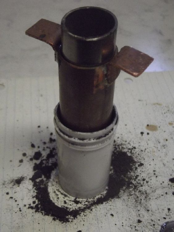
ointment jar? I found a stainless steel pipe that seemed about
right for a cylinder. (It doesn't have to be solid.) Then I
discovered that a 1 inch copper pipe was pretty much a perfect
telescoping tube around that.
Amazing! With that piece of "luck" I was convinced to
start over.
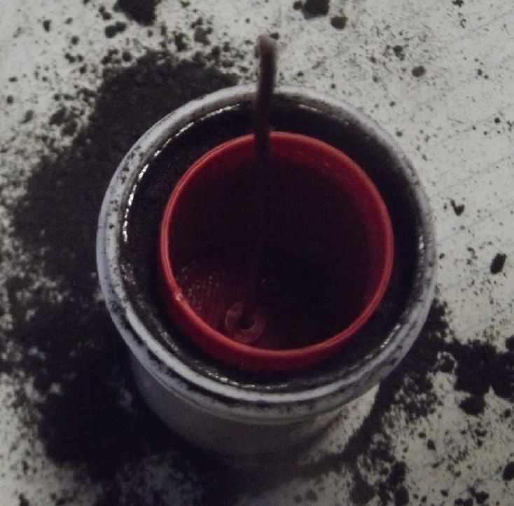
I
cut
the pipes to what I hoped were suitable lengths. I cut a piece of
graphite and put it around the rim of the jar. I put the stainless
pipe in. Then I fed in some bits of powder around the edge with a
tiny spoon. Then I tamped it with the copper pipe. I couldn't get
much pressure with the copper pipe, since I could only touch it
around the edges and it went most of the way into the jar. I took
it out and soldered a couple of "handles" onto the copper to press
down on. That seemed much better. The stainless pipe should have
been an inch longer. The copper pipe came right to the top of it
when pulling it out so it was hard to hold it in place in the cell
when taking the copper pipe off to add more powder. (The leftover
piece was shorter and bent on the end. Finding more the same would
probably be hard.)
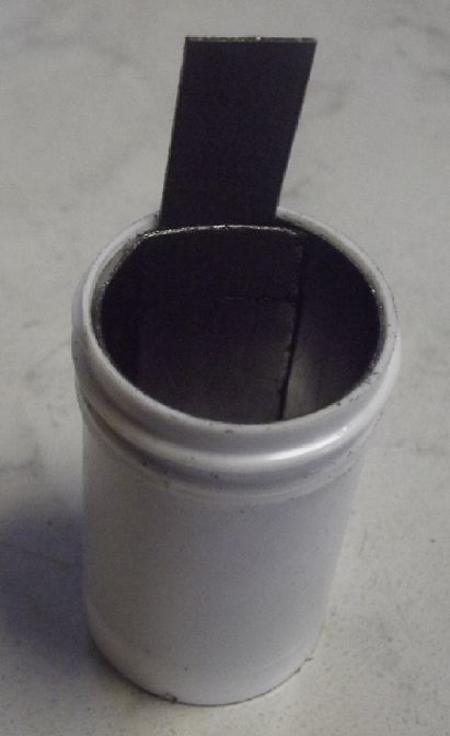
Jar + graphite sheet: 10.5 grams
add organic mix: 21.6 grams (so 11.1 g of electrode mix)
 While
I
was waiting for the propane to warm up for that, I changed the 3D
print design. The changes were mostly to dimensions - a fatter tub
- so it was pretty simple. I printed one. The top fit about right.
The "skirt" around the outside at the bottom that I put on to make
sure the print didn't come loose while printing had to be cut off
and made flush. The scissor blade rode up and cut into the side.
Then when I was filing around the bottom it broke off. Ug! I glued
it together again with methylene chloride and a couple of the
scrap pieces.
While
I
was waiting for the propane to warm up for that, I changed the 3D
print design. The changes were mostly to dimensions - a fatter tub
- so it was pretty simple. I printed one. The top fit about right.
The "skirt" around the outside at the bottom that I put on to make
sure the print didn't come loose while printing had to be cut off
and made flush. The scissor blade rode up and cut into the side.
Then when I was filing around the bottom it broke off. Ug! I glued
it together again with methylene chloride and a couple of the
scrap pieces.
 The
basket
seemed to go into the filled jar just about right - I was feeling
just a little resistance shoving it down. When I pulled it out it
broke up the mix crunched into the outer rim beside the graphite
sheet. If it hadn't, the basket might be said to have been too
loose a fit. Normally of course the zinc basket will never be
pulled out again. I just put it in for the 'fit' test.
The
basket
seemed to go into the filled jar just about right - I was feeling
just a little resistance shoving it down. When I pulled it out it
broke up the mix crunched into the outer rim beside the graphite
sheet. If it hadn't, the basket might be said to have been too
loose a fit. Normally of course the zinc basket will never be
pulled out again. I just put it in for the 'fit' test.
A major redesign - some great improvements and
several things proven to work nicely. A good day!
---
* SDBS: again, sigh... sodium
dodecylbenzenesulfonate. Soapy stuff. Zincate and cuprate ions
won't penetrate this.
[27th] I cut some pieces of watercolor paper to size (46 x 70 mm),
then soaked them in toluene and dried them, twice.
My bottle of SDBS had finally run out. It took quite
a few flushings to rinse out the suds from the bottle. I looked in
back issues of TE News to see what proportions I had used.
Evidently I hadn't recorded it. If memory serves it was about a
rounded teaspoon of SDBS in a drink bottle. This time I measured
the teaspoon, 5.5 grams, and the pure water to fill the bottle,
200 cc. Then I painted the watercolor papers, thoroughly soaked,
both sides, and set them above the woodstove again. (Previously I
had poured the bottle into a shallow container and left papers in
that to soak it up for ten minutes. This time somehow I hadn't
thought of that. Hmm... is there a difference?
When they were dry, I got out the new vial of osmium
powder. The old one from Alfa Aser (2008?) was narrow enough to
pour straight into a small test tube. The new one was too fat. I
didn't want to loose a bit of powder in a funnel each time - that
gram of powder was 2 or 3 hundred dollars. So I used a funnel to
pour it into the old vial. Then I poured some acetaldehyde from
its bottle into the new vial, put the lid on and shook it to get
the remnant. I poured that through the funnel into the test tube,
picking up remnant from the funnel. The slightly dark color in the
tube said that was enough osmium. I painted a paper with this,
both sides. This is supposed to be a surface layer, a film, but
certainly a lot of it soaked into the paper. This time I didn't
want to heat it, so I left it on the counter to dry.
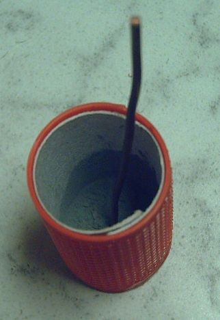
Then I curled it around a tube and
put it into the electrode cylinder. I added 5 grams of zinc and a
trace of zircon. I pushed a #14 solid wire in through the cap into
the recess in the bottom. Then I glued the cap on.
(Something that has been bothering me... I can add the
zirconium silicate powder to the zinc powder as a hydrogen
overvoltage raising additive, but I don't know how it'll stay
mixed in as the zinc dissolves and replates. ...I won't worry
about it for now.)
 I
inserted
the cylinder into the cell. Again it seemed to be just rubbing on
the organic copper mix all around it a bit. In the lid I had
printed a 12 mm wide slot for the "plus" terminal. I stuck a piece
of metal into the slot to push some mix away, then a piece of
graphite foil. It seemed loose. I added a second and a third
piece, making it thicker. That seemed good enough. Then I squirted
in 10 cc of electrolyte.
I
inserted
the cylinder into the cell. Again it seemed to be just rubbing on
the organic copper mix all around it a bit. In the lid I had
printed a 12 mm wide slot for the "plus" terminal. I stuck a piece
of metal into the slot to push some mix away, then a piece of
graphite foil. It seemed loose. I added a second and a third
piece, making it thicker. That seemed good enough. Then I squirted
in 10 cc of electrolyte.
The cell started off saying ~.5 V, but it dropped
gradually. I considered that the loose zinc powder probably wasn't
making a very good connection with the wire. It needed some of it
to be discharged to Zn(OH)4-- and recharged
to plate onto the wire and gradually connect all the pieces
together. (In this cell, for this purpose, lumpy plating and
dendrites become advantages instead of problems!) But if it was
already fully charged to metallic state, and the plus was
(obviously) fully discharged, how was any to be discharged to
begin the process?
I shorted out the cell through the 300 mA current
plug on the multimeter (which is really around 5 ohms, not a
short). It started out at 1.2 mA and soon was down to .6 . Then
the meter complained that its battery was low. So I took
it off and put in a charged battery (9V NiMH). When I came back,
it read .00 or .01 mA. But it gradually came back to over 1 mA. By
bedtime it was .9 mA and in the morning it was still .7 mA.
Nothing fast here, but it should be making at least a few
zincate ions to use for starting to properly charge the zinc into
solid connections.
In a way I was sorry to have glued the top on the
electrode cylinder. That meant I couldn't take the top off the
cell without pulling out the zinc'trode, which would rip up the
'plus' substance. I could possibly stick a pH paper into the slot
with the graphite foil electrode. I couldn't check the electrolyte
level. OTOH, presumably no zinc ions could seep over the rim and
get out of the cylinder!
[28th] 'Short circuit' current went for .7 mA to .4 . I decided to
keep it going.
[29th]
Current
was down to .10 mA in the morning, but later rose to .22 mA and
stayed there until evening. I disconnected it in the evening. The
test leed wires almost dragged the cell off the counter. This has
happened before and I'd had enough of it. I took an ugly block of
wood and drilled a hole in it to fit the cell into.
Soon I moved it more safely toward the back of the
counter. At least it's a lot heavier than the wires and they'd
have to drag it a fair ways.
[30th] Voltage rose by itself to almost 1/2 a volt. I put a very
slow charge on around 9 AM, which soon tapered to about 1.0 mA
with a voltage reading of 1.146. Why push it?
I couldn't pull the cell open without destroying it
anyway, so I glued the top onto the jar. I printed another
electrode cylinder basket to have an unfilled cell that I could
show.
[Dec 1st] I raised the voltage to ~1.5V. It stayed up there
drawing half a milliamp. It would drive a 100 ohm load at over 1.2
volts momentarily, but it faded fast. Next time I'll time its drop
to 1.00V. So far it doesn't seem like much of a battery.
Electricity
Generation
New Grid-Tied Solar Power System
Well, mea culpa. By the time the solar panels
installation was complete and the electrician said I should get an
email from BC Hydro, I had forgotten that I was supposed to go
back on line and fill out more information: the total cost of the
project and the final electrical inspection report. The inspection
was a "remote inspection" apparently of the photos taken by me
during the panels installation and the electrician during and
after the hookup of the panels through a roof box, outdoor shutoff
switch box (for BC Hydro if they ever need to shut it off) then
into the house breaker box. Also the contractor had had trouble
with the inspector's web page when he applied for the final
inspection approval on line, and he hadn't actually received it.
So on my saying I needed it he emailed the inspector
and finally got and sent me the final approval in writing (PDF),
and I rounded up the PDF invoices and totaled the invoiced costs
(17,889.82 $C), and I went to the BC Hydro web page and sent them
all. No doubt now that email from Hydro authorizing me to turn it
on will come in its own good time. And the 5000 $ rebate. For some
reason had I thought getting final approval from the inspector
would have triggered everything automaticly, and having heard
nothing, I thought for far too long it must have been "in
process". Presumably it now is.
My (Old) Solar Power System(s)
(My solar panels recent images - TE News #200)
The Usual Daily/Monthly/Yearly
Log of Solar Power Generated [and grid power consumed]
Notes:
* All times are in PST: clock ~48 minutes ahead of local
sun time, never PDT which is an hour and 48 minutes ahead.
* Unapproved AC/Grid Tied systems have been removed.
* House panels include four old ones on the roof (upper - total
rating ~ 1000W), two 305W on the roof, three 305W on the south
wall below the roof, and one broken panel mounted verticly on the
porch railing (seems to still work but a lot of shade there).
* Cabin DC includes the three carport panels and the two on a pole
in the yard as well as the four on the cabin roof itself. All nine
are 305W.
* The wall, pole and porch panels are easily wiped off from the
ground if it snows.
* Km = Nissan Leaf electric car drove distance, then car was
charged. Car KWH does not add to or subtract from any other
readings.
House System Panels: House roof, wall (9 solar panels) -
Porch (1 broken one - usually shady)
Cabin System Panels: Carport (3 - sunniest place on the
whole property) - Pole (2 - shadiest place) -Faraday Cabin (4 -
badly shaded in winter)
New Order of Daily Solar Readings (Beginning November 2024):
Date HouseDC, CabinDC => Total KWH Solar [Notable power Uses
(EV); Grid power meter@time] Sky/weather, notes...
October
31st 1022.59, 727.31 => 2.68 [85Km; 32815@18:00]
November
1st 1023.74, 728.89 => 2.73 [32845@20:00]
2d 1026.14, 730.80 => 4.31 [32876@18:00]
3rd 1028.63, 732.87 => 4.56 [32912@17:30]
4th 1029.22, 733.37 => 1.09 [55Km; 32953@17:30]
5th 1030.02, 734.77 => 2.20 [45Km; 33001@'24:30']
6th 1031.70, 736.08 => 2.99 [33030@20:30]
7th 1034.62, 737.77 => 4.61 [33074@'24:00']
8th 1034.79, 738.22 => .62 [105Km;
33115@20:00]
9th 1036.89, 739.99 => 3.87 [33153@'24:00']
10th 1038.19, 741.35 => 2.66 [33193@17:00]
11th 1041.04, 743.45 => 4.95 [50Km; 33235@19:00]
12th 1043.32, 745.17 => 4.00 [55Km; 33278@20:30]
13th 1045.43, 746.59 => 3.53 [33316@17:30]
14th 1046.09, 747.51 => 1.58 [33356@19:00]
15th 1047.09, 748.72 => 2.21 [33392@20:00]
16th 1049.32, 750.02 => 3.53 [33438@22:00]
17th 1050.49, 751.02 => 2.17 [55Km; 33475@18:30]
18th 1051.19, 751.79 => 1.47 [33498@18:00]
19th 1052.60, 752.43 => 2.05 [33522@16:30]
20th 1053.31, 753.26 => 1.54 [33552@18:30]
21st 1055.77, 755.51 => 4.71 [33577@18:00]
22d 1057.63, 756.25 => 2.50 [55Km@20:30; 55Km]
23rd 1059.82, 757.92 => 3.86 [33658@20:00] ...even with
sunshine, only around 4 KW.
24th 1062.52, 759.27 => 4.05 [33688@22:30]
25th 1062.98, 759.89 => 1.08 [ -- ] .................without
sunshine is worse.
26th 1065.47, 761.57 => 4.17 [33741@18:30]
27th 1067.21, 763.30 => 3.47 [33782@22:30]
28th 1067.81, 763.97 => 1.27 [90Km; 33809@16:00]
29th 1068.21, 764.61 => 1.04 [75Km; 33861@17:00]
30th 1068.51, 765.15 => .84 [33903@17:00]
December
1st 1070.21, 766.34 => 2.89 [33936@18:00]
Chart of daily KWH from solar panels. (Compare November 2025 with October 2025 &
November 2024.)
Days of
__ KWH
|
November
2025
|
October 2025
|
November 2024
(18 C's - Grid
Ties & DC)
|
0.xx
|
2
|
|
4
|
1.xx
|
7
|
2
|
9
|
2.xx
|
8
|
10
|
6
|
3.xx
|
5
|
5
|
4
|
4.xx
|
8
|
5
|
2
|
5.xx
|
|
5
|
3
|
6.xx
|
|
1
|
|
7.xx
|
|
2
|
1
|
8.xx
|
|
1
|
|
9.xx
|
|
|
1
|
10.xx
|
|
|
|
11.xx
|
|
|
|
12.xx
|
|
|
|
13.xx
|
|
|
|
Total KWH
for month
|
83.46
|
134.08
|
84.69
|
Km Driven
on Electricity
|
926.2 Km
@7.4 Km/KWH
= 125 KWH
|
400.9 Km
@8.0 Km/KWH
= 50 KWH |
778.8 Km
~110 KWH
|
Things Noted - November 2025
* The low KWH generated is mostly from lack of solar energy. I was
using pretty much all of what little was available in electric
heaters. Without wanting to run the batteries too low, they were
also rarely fully charged. The weather was rarely sunny.
* With using it all, the total generated for the month was
virtually the same as last year. November 2024 was the last month
power was (mostly) sent to the grid.
* October 2024 sent 198.43 KWH 'to the grid'. A couple of years
were over 200. October 2025 gave only 134 KWH to the batteries.
Much of that went to heating. This probably shows how much goes to
waste when the panels aren't putting out everything they can into
an 'infinitely' hungry load.
* The drop in "house" versus "cabin" solar generated compared to
October and earlier reflects the tree shadows covering the house
roof for much of the day at this time of year. The cabin also gets
shaded but the carport roof (connected to the cabin system) still
gets a lot of sun in winter, so the "cabin" didn't drop much from
October.
Monthly Summaries: Solar Generated KWH [& Power
used from grid KWH]
As these tables are getting long, I'm not repeating the log of
monthly reports. The reports for the SIX full years (March 2019 to
February 2025) may be found in TE News #201, February 2025.
Note that in November 2024 I had to disconnect the "unapproved"
solar power systems from the power grid, and I have been running
them as two "off grid" 300 amp-hour, 36 volt, battery systems
since.
2024
Month: HouseAC + DC +Carport+Cabin[+DC] (from Aug 2024)
Oct KWH 78.48+ 7.29 + 64.39 + 7.52 + 40.75 =
198.43 [grid: 711; car: 120*]
Nov KWH 19.63+12.19+ 23.90 + 3.35 + 25.62
= 84.69 [grid: 900 (ACK!);car: 110*] Changed solar system to "off grid only" on 18th.
Now solar is charging
batteries only. Two 36 V DC systems: house, cabin, each 10
KWH, each 9 solar panels once wired.
Dec KWH 20.37 + 16.76 = 37.13 [grid: 1866 (using electric
heat - awg!); car: 120*]
2025
Jan KWH 35.02 + 26.30 = 61.32 [grid: 2136 (electric
heat OW!); car: 120*]
Feb KWH 55.43 + 39.00 = 94.43 [grid: 1937; car: 100*]
SIX full Years of
solar!
Mar KWH 115.13 + 87.41 = 202.54
[grid: 1860; car: 155* KWH]
Apr KWH 126.25 + 120.36 = 246.61 [grid: 1246; car: 100*]
May KWH 147.08 + 186.24 = 333.32 [grid: 1354; car: 150*]
Jun 145.58 + 170.97 = 316.55 [grid: 959; car: 130*]
July 156.48+ 86.78 = 243.26 [grid: 653; car 130]
Aug 118.56 + 48.50 = 167.06 [grid: 616; car 150]
Sept 115.15+ 63.87 = 179.02 [grid: 576; car: trip meter reading
lost with 12V battery replacement]
Oct 93.22 + 40.86 = 134.08 [grid: 868; car: 50]
Nov 45.62 + 37.84 = 83.46 [1088; car: 125]
* Car consumption comes from solar and or
grid: it does not add to other figures. (Just from grid from
Nov. 18th. 2024 except some direct solar charging summer 2025)
Annual Totals
1. March 2019-Feb. 2020: 2196.15 KWH Solar [used 7927
KWH from grid; EV use: -] 10, 11, 12 solar panels
2. March 2020-Feb. 2021: 2069.82 KWH Solar [used 11294 KWH from
grid; EV use: - (More electric heat - BR, Trailer & Perry's
RV)] 12 solar panels
3. March 2021-Feb. 2022: 2063.05 KWH Solar [used 10977 KWH from
grid; EV use ~~1485 KWH] 12 solar panels, 14 near end of year.
4a. March 2022-August 2022: in (the best) 6 months, about 2725 KWH
solar - more than in any previous entire year!
4. March2022-Feb. 2023: 3793.37 KWH Solar [used 12038 KWH from
grid; EV use: ~1583 KWH] 14, 15, 18 solar panels
5. March 2023-Feb. 2024: 3891.35 KWH Solar [used 7914 KWH from
power grid; EV use: ~1515 KWH] 18 solar panels
6. March 2024-Feb. 2025: 3428.88 KWH Solar [used 12773 KWH from
grid; EV used: ~1685 KWH]
Money Saved or Earned - @ 12¢ [All BC residential elec.
rate] ; @ 50¢ [2018 cost of diesel fuel to BC Hydro] ; @ 1$ per
KWH [actual total cost to BC Hydro in 2022 according to an
employee]; or maybe it's 62 ¢/KWH [according to BC Hydro at
Renewable Energy Symposium Sept. 2024]:
1. 263.42$ ; 1097.58$ ; 2196.15$
2. 248.38$ ; 1034.91$ ; 2069.82$
3. 247.57$ ; 1031.53$ ; 2063.05$
4. 455.20$ ; 1896.69$ ; 3793.37$
5. 466.96$ ; 1945.68$ ; 3891.35$
6. 411.47$ ; 1714.44$ ; 3428.88$
I had to disconnect the system from the grid in
November 2024. These two now independent installations (house,
cabin) will continue to run their 36 volt DC systems and I'll see
how I can most effectively utilize the available solar energy with
the limited available storage.
http://www.TurquoiseEnergy.com
Haida Gwaii, BC Canada